EP3396239B1 - Lampenanordnung zur verwendung in einem scheinwerfer - Google Patents
Lampenanordnung zur verwendung in einem scheinwerfer Download PDFInfo
- Publication number
- EP3396239B1 EP3396239B1 EP18167329.4A EP18167329A EP3396239B1 EP 3396239 B1 EP3396239 B1 EP 3396239B1 EP 18167329 A EP18167329 A EP 18167329A EP 3396239 B1 EP3396239 B1 EP 3396239B1
- Authority
- EP
- European Patent Office
- Prior art keywords
- lamp assembly
- heat sink
- light source
- headlamp
- circuit board
- Prior art date
- Legal status (The legal status is an assumption and is not a legal conclusion. Google has not performed a legal analysis and makes no representation as to the accuracy of the status listed.)
- Active
Links
Images


Classifications
-
- F—MECHANICAL ENGINEERING; LIGHTING; HEATING; WEAPONS; BLASTING
- F21—LIGHTING
- F21S—NON-PORTABLE LIGHTING DEVICES; SYSTEMS THEREOF; VEHICLE LIGHTING DEVICES SPECIALLY ADAPTED FOR VEHICLE EXTERIORS
- F21S41/00—Illuminating devices specially adapted for vehicle exteriors, e.g. headlamps
-
- F—MECHANICAL ENGINEERING; LIGHTING; HEATING; WEAPONS; BLASTING
- F21—LIGHTING
- F21S—NON-PORTABLE LIGHTING DEVICES; SYSTEMS THEREOF; VEHICLE LIGHTING DEVICES SPECIALLY ADAPTED FOR VEHICLE EXTERIORS
- F21S45/00—Arrangements within vehicle lighting devices specially adapted for vehicle exteriors, for purposes other than emission or distribution of light
- F21S45/40—Cooling of lighting devices
- F21S45/47—Passive cooling, e.g. using fins, thermal conductive elements or openings
-
- B—PERFORMING OPERATIONS; TRANSPORTING
- B60—VEHICLES IN GENERAL
- B60Q—ARRANGEMENT OF SIGNALLING OR LIGHTING DEVICES, THE MOUNTING OR SUPPORTING THEREOF OR CIRCUITS THEREFOR, FOR VEHICLES IN GENERAL
- B60Q1/00—Arrangement of optical signalling or lighting devices, the mounting or supporting thereof or circuits therefor
- B60Q1/02—Arrangement of optical signalling or lighting devices, the mounting or supporting thereof or circuits therefor the devices being primarily intended to illuminate the way ahead or to illuminate other areas of way or environments
- B60Q1/04—Arrangement of optical signalling or lighting devices, the mounting or supporting thereof or circuits therefor the devices being primarily intended to illuminate the way ahead or to illuminate other areas of way or environments the devices being headlights
-
- F—MECHANICAL ENGINEERING; LIGHTING; HEATING; WEAPONS; BLASTING
- F21—LIGHTING
- F21S—NON-PORTABLE LIGHTING DEVICES; SYSTEMS THEREOF; VEHICLE LIGHTING DEVICES SPECIALLY ADAPTED FOR VEHICLE EXTERIORS
- F21S41/00—Illuminating devices specially adapted for vehicle exteriors, e.g. headlamps
- F21S41/10—Illuminating devices specially adapted for vehicle exteriors, e.g. headlamps characterised by the light source
- F21S41/14—Illuminating devices specially adapted for vehicle exteriors, e.g. headlamps characterised by the light source characterised by the type of light source
- F21S41/141—Light emitting diodes [LED]
-
- F—MECHANICAL ENGINEERING; LIGHTING; HEATING; WEAPONS; BLASTING
- F21—LIGHTING
- F21S—NON-PORTABLE LIGHTING DEVICES; SYSTEMS THEREOF; VEHICLE LIGHTING DEVICES SPECIALLY ADAPTED FOR VEHICLE EXTERIORS
- F21S41/00—Illuminating devices specially adapted for vehicle exteriors, e.g. headlamps
- F21S41/10—Illuminating devices specially adapted for vehicle exteriors, e.g. headlamps characterised by the light source
- F21S41/19—Attachment of light sources or lamp holders
- F21S41/192—Details of lamp holders, terminals or connectors
-
- F—MECHANICAL ENGINEERING; LIGHTING; HEATING; WEAPONS; BLASTING
- F21—LIGHTING
- F21S—NON-PORTABLE LIGHTING DEVICES; SYSTEMS THEREOF; VEHICLE LIGHTING DEVICES SPECIALLY ADAPTED FOR VEHICLE EXTERIORS
- F21S41/00—Illuminating devices specially adapted for vehicle exteriors, e.g. headlamps
- F21S41/20—Illuminating devices specially adapted for vehicle exteriors, e.g. headlamps characterised by refractors, transparent cover plates, light guides or filters
- F21S41/24—Light guides
-
- F—MECHANICAL ENGINEERING; LIGHTING; HEATING; WEAPONS; BLASTING
- F21—LIGHTING
- F21S—NON-PORTABLE LIGHTING DEVICES; SYSTEMS THEREOF; VEHICLE LIGHTING DEVICES SPECIALLY ADAPTED FOR VEHICLE EXTERIORS
- F21S43/00—Signalling devices specially adapted for vehicle exteriors, e.g. brake lamps, direction indicator lights or reversing lights
- F21S43/10—Signalling devices specially adapted for vehicle exteriors, e.g. brake lamps, direction indicator lights or reversing lights characterised by the light source
- F21S43/13—Signalling devices specially adapted for vehicle exteriors, e.g. brake lamps, direction indicator lights or reversing lights characterised by the light source characterised by the type of light source
- F21S43/14—Light emitting diodes [LED]
-
- F—MECHANICAL ENGINEERING; LIGHTING; HEATING; WEAPONS; BLASTING
- F21—LIGHTING
- F21S—NON-PORTABLE LIGHTING DEVICES; SYSTEMS THEREOF; VEHICLE LIGHTING DEVICES SPECIALLY ADAPTED FOR VEHICLE EXTERIORS
- F21S43/00—Signalling devices specially adapted for vehicle exteriors, e.g. brake lamps, direction indicator lights or reversing lights
- F21S43/10—Signalling devices specially adapted for vehicle exteriors, e.g. brake lamps, direction indicator lights or reversing lights characterised by the light source
- F21S43/19—Attachment of light sources or lamp holders
- F21S43/195—Details of lamp holders, terminals or connectors
-
- F—MECHANICAL ENGINEERING; LIGHTING; HEATING; WEAPONS; BLASTING
- F21—LIGHTING
- F21S—NON-PORTABLE LIGHTING DEVICES; SYSTEMS THEREOF; VEHICLE LIGHTING DEVICES SPECIALLY ADAPTED FOR VEHICLE EXTERIORS
- F21S43/00—Signalling devices specially adapted for vehicle exteriors, e.g. brake lamps, direction indicator lights or reversing lights
- F21S43/20—Signalling devices specially adapted for vehicle exteriors, e.g. brake lamps, direction indicator lights or reversing lights characterised by refractors, transparent cover plates, light guides or filters
- F21S43/235—Light guides
- F21S43/236—Light guides characterised by the shape of the light guide
- F21S43/237—Light guides characterised by the shape of the light guide rod-shaped
-
- F—MECHANICAL ENGINEERING; LIGHTING; HEATING; WEAPONS; BLASTING
- F21—LIGHTING
- F21S—NON-PORTABLE LIGHTING DEVICES; SYSTEMS THEREOF; VEHICLE LIGHTING DEVICES SPECIALLY ADAPTED FOR VEHICLE EXTERIORS
- F21S43/00—Signalling devices specially adapted for vehicle exteriors, e.g. brake lamps, direction indicator lights or reversing lights
- F21S43/20—Signalling devices specially adapted for vehicle exteriors, e.g. brake lamps, direction indicator lights or reversing lights characterised by refractors, transparent cover plates, light guides or filters
- F21S43/235—Light guides
- F21S43/242—Light guides characterised by the emission area
- F21S43/243—Light guides characterised by the emission area emitting light from one or more of its extremities
-
- F—MECHANICAL ENGINEERING; LIGHTING; HEATING; WEAPONS; BLASTING
- F21—LIGHTING
- F21S—NON-PORTABLE LIGHTING DEVICES; SYSTEMS THEREOF; VEHICLE LIGHTING DEVICES SPECIALLY ADAPTED FOR VEHICLE EXTERIORS
- F21S43/00—Signalling devices specially adapted for vehicle exteriors, e.g. brake lamps, direction indicator lights or reversing lights
- F21S43/20—Signalling devices specially adapted for vehicle exteriors, e.g. brake lamps, direction indicator lights or reversing lights characterised by refractors, transparent cover plates, light guides or filters
- F21S43/235—Light guides
- F21S43/247—Light guides with a single light source being coupled into the light guide
-
- F—MECHANICAL ENGINEERING; LIGHTING; HEATING; WEAPONS; BLASTING
- F21—LIGHTING
- F21S—NON-PORTABLE LIGHTING DEVICES; SYSTEMS THEREOF; VEHICLE LIGHTING DEVICES SPECIALLY ADAPTED FOR VEHICLE EXTERIORS
- F21S43/00—Signalling devices specially adapted for vehicle exteriors, e.g. brake lamps, direction indicator lights or reversing lights
- F21S43/20—Signalling devices specially adapted for vehicle exteriors, e.g. brake lamps, direction indicator lights or reversing lights characterised by refractors, transparent cover plates, light guides or filters
- F21S43/27—Attachment thereof
-
- F—MECHANICAL ENGINEERING; LIGHTING; HEATING; WEAPONS; BLASTING
- F21—LIGHTING
- F21V—FUNCTIONAL FEATURES OR DETAILS OF LIGHTING DEVICES OR SYSTEMS THEREOF; STRUCTURAL COMBINATIONS OF LIGHTING DEVICES WITH OTHER ARTICLES, NOT OTHERWISE PROVIDED FOR
- F21V23/00—Arrangement of electric circuit elements in or on lighting devices
- F21V23/003—Arrangement of electric circuit elements in or on lighting devices the elements being electronics drivers or controllers for operating the light source, e.g. for a LED array
-
- F—MECHANICAL ENGINEERING; LIGHTING; HEATING; WEAPONS; BLASTING
- F21—LIGHTING
- F21V—FUNCTIONAL FEATURES OR DETAILS OF LIGHTING DEVICES OR SYSTEMS THEREOF; STRUCTURAL COMBINATIONS OF LIGHTING DEVICES WITH OTHER ARTICLES, NOT OTHERWISE PROVIDED FOR
- F21V31/00—Gas-tight or water-tight arrangements
- F21V31/005—Sealing arrangements therefor
-
- H—ELECTRICITY
- H05—ELECTRIC TECHNIQUES NOT OTHERWISE PROVIDED FOR
- H05K—PRINTED CIRCUITS; CASINGS OR CONSTRUCTIONAL DETAILS OF ELECTRIC APPARATUS; MANUFACTURE OF ASSEMBLAGES OF ELECTRICAL COMPONENTS
- H05K1/00—Printed circuits
- H05K1/02—Details
- H05K1/0201—Thermal arrangements, e.g. for cooling, heating or preventing overheating
- H05K1/0203—Cooling of mounted components
-
- B—PERFORMING OPERATIONS; TRANSPORTING
- B60—VEHICLES IN GENERAL
- B60Q—ARRANGEMENT OF SIGNALLING OR LIGHTING DEVICES, THE MOUNTING OR SUPPORTING THEREOF OR CIRCUITS THEREFOR, FOR VEHICLES IN GENERAL
- B60Q2400/00—Special features or arrangements of exterior signal lamps for vehicles
- B60Q2400/30—Daytime running lights [DRL], e.g. circuits or arrangements therefor
-
- F—MECHANICAL ENGINEERING; LIGHTING; HEATING; WEAPONS; BLASTING
- F21—LIGHTING
- F21W—INDEXING SCHEME ASSOCIATED WITH SUBCLASSES F21K, F21L, F21S and F21V, RELATING TO USES OR APPLICATIONS OF LIGHTING DEVICES OR SYSTEMS
- F21W2107/00—Use or application of lighting devices on or in particular types of vehicles
- F21W2107/10—Use or application of lighting devices on or in particular types of vehicles for land vehicles
-
- F—MECHANICAL ENGINEERING; LIGHTING; HEATING; WEAPONS; BLASTING
- F21—LIGHTING
- F21Y—INDEXING SCHEME ASSOCIATED WITH SUBCLASSES F21K, F21L, F21S and F21V, RELATING TO THE FORM OR THE KIND OF THE LIGHT SOURCES OR OF THE COLOUR OF THE LIGHT EMITTED
- F21Y2115/00—Light-generating elements of semiconductor light sources
- F21Y2115/10—Light-emitting diodes [LED]
-
- H—ELECTRICITY
- H05—ELECTRIC TECHNIQUES NOT OTHERWISE PROVIDED FOR
- H05K—PRINTED CIRCUITS; CASINGS OR CONSTRUCTIONAL DETAILS OF ELECTRIC APPARATUS; MANUFACTURE OF ASSEMBLAGES OF ELECTRICAL COMPONENTS
- H05K2201/00—Indexing scheme relating to printed circuits covered by H05K1/00
- H05K2201/10—Details of components or other objects attached to or integrated in a printed circuit board
- H05K2201/10007—Types of components
- H05K2201/10106—Light emitting diode [LED]
Definitions
- This invention relates to motor vehicle headlamps and, more particularly, to a lamp assembly that is situated in a headlamp.
- LEDs may be used in combination with a light pipe to provide a vehicle lighting function.
- the LEDs were mounted directly to a printed circuit board (PCB) which in turn was mounted to a heat sink that was required to dissipate heat generated by the printed circuit board and the LEDs which were mounted thereon.
- the light pipe was typically situated such that its input face was positioned in operative relationship with the LEDs.
- the heat sink was then mounted outside the headlamp to a housing on the vehicle. This required that the heat sink be sealed or to be sealed to the housing. Therefore, a seal had to be provided to seal the heat sink and the components mounted thereon, including the printed circuit board and the LEDs. Because the LEDs were mounted directly to the printed circuit board, which in turn was mounted to the heat sink, a relatively large heat sink was necessary to dissipate the heat from both of these components.
- Another object of the invention is to provide an assembly wherein at least one or a plurality of LEDs can be submounted on the heat sink separate from a printed circuit board, thereby enabling a size of the heat sink to be reduced.
- Yet another object of the invention is to provide a lamp assembly wherein a light pipe can be mounted to the heat sink before the assembly is loaded into a lamp.
- Still another object of the invention is to improve the heat transmission efficiency and heat dissipation of the printed circuit board and the at least one or a plurality of LEDs.
- Still another object of the invention is to provide a lamp assembly that can be situated directly in the headlamp, thereby eliminating the need for a seal.
- Another object of the invention is to provide a processed, folded or stamped heat sink that has at least one or a plurality of protectors for protecting the components that are mounted on the heat sink.
- Yet another object of the invention is to provide a system and assembly that facilitates reducing the cost of a lamp assembly.
- Another object of the invention is to provide a system and assembly that is modular and is adapted to precisely load components, such as a circuit board, LED and/or light pipe, onto a heat sink so that the components are registered in a predetermined position thereon.
- components such as a circuit board, LED and/or light pipe
- the invention features a lamp assembly according to the appended claim 1.
- Optional features of the lamp assembly according to the invention are described in the dependent claims.
- the invention comprises a headlamp according to the claim 8.
- Optional features of the headlamp are described in the dependent claim 9.
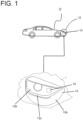
- a lamp assembly 10 is shown mounted in a headlamp assembly 12 of a vehicle V.
- the headlamp assembly 12 comprises a bezel or housing 12a, a lens 12b and a seal 12c that generally seals the lamp assembly 10 in the headlamp assembly 12.
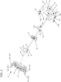
- the lamp assembly 10 comprises a heat sink 14 which is stamped from a single piece of material (not shown) and configured as illustrated in the exploded view of Fig. 2 .
- the heat sink 14 is a one-piece integral or monolithic construction and is processed or folded to comprise a first wall 14a, a second wall 14b ( Fig.
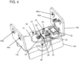
- the heat sink 14 comprises a crescent or half-moon shaped landing pad or area 16 that is adapted to receive a light source 18 which may comprise at least one or a plurality of light-emitting diodes (LEDs) 20.
- a light source 18 which may comprise at least one or a plurality of light-emitting diodes (LEDs) 20.
- the at least one LED 20 is mounted on the landing pad or area 16 using a conventional adhesive.
- the heat sink 14 may be coated or treated, such as by anodizing the heat sink 14, to facilitate heat transfer from the light source 18 to the heat sink 14 .
- the landing pad or area 16 does not have any coating in order to improve the adhesion of the at least one LED 20 to the landing pad or area 16.
- the landing pad or area 16 is laser ablated to facilitate adhering the at last one LED 20 thereto.
- the heat sink 14 comprises a plurality of registration posts 24.
- a thermal compound 26 comprises a plurality of walls 26a that define a plurality of apertures 28 that receive the posts 24 and register the thermal compound 26 on a printed circuit board landing area 27 ( Fig. 2 ) on the heat sink 14 and in operative relationship with the landing pad or area 16. It should be understood that the thermal compound 26 adheres the printed circuit board 30 to the heat sink 14 and also provides a thermal conductivity between the printed circuit board 30 and heat sink 14.
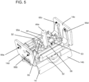
- a printed circuit board (PCB) 30 is mounted to the printed circuit board landing area 27 with the thermal compound 26. The printed circuit board 30 controls the operation of the light source 18 and at least one LED 20. The printed circuit board 30 is mounted on the thermal compound 26 as shown. In this regard and as best illustrated in Figs. 2 and 5 , note that the printed circuit board 30 comprises a plurality of apertures 32 that receive the registration posts 24 which causes an automatic registration of the printed circuit board 30 relative to the landing pad or area 16.
- the printed circuit board 30 comprises a female connector 35 ( Figs. 4 and 8 ) coupling to a power source (not shown) of the vehicle V.
- the printed circuit board 30 also comprises a plurality of vias or conductors 38 for coupling to the light source 18.
- a plurality of electrical conductors 42 electrically couple the printed circuit board 30 to the light source 18.
- the lamp assembly 10 comprises a light pipe 44 having a plurality of projections 46 that are received in apertures 48 in the heat sink 14.
- the projections 46 of the light pipe 44 are frustoconically shaped in cross-section so that they are easily received in the apertures 48, and when press-fit, an input face 50 of the light pipe 44 becomes automatically registered a predetermined distance relative to the light source 18.
- a bracket 52 is mounted on the heat sink 14 and engages a surface or shoulder 56 of the light pipe 44 in order to retain it in a locked or secured position in the lamp assembly 10.
- the exit face 44a ( Figs. 2 , 5 , 7 and 9 ) of the light pipe 44 is guided through an aperture 53 of the bracket 52.
- the bracket 52 comprises a plurality of resilient arms 55 having ends, such as end 55a ( Fig. 6 ), that engage the shoulder 56 ( Fig. 2 ) and hold it in a locked position on the heat sink 14.
- the bracket 52 also has resilient locking arms 52a-52d having ends or detents 52a1-52d1, respectively, that are received in apertures 66a, 66b 66c and 66d ( Figs. 2-5 , 8 and 10 ) in the heat sink 14 as illustrated in Fig. 2 .
- the resilient arms 52a-52d force the ends or detents 52a1-52d1, respectively, into the apertures 66a-66d, thereby locking the bracket 52 onto the heat sink 14.
- the lamp assembly 10 After assembly of the lamp assembly 10, the lamp assembly 10 is mounted in the headlamp assembly 12, which is sealed from weather and debris.
- the light source 18 is mounted directly to the heat sink 14, rather than the printed circuit board 30 as was done in the prior art, a smaller heat sink 14 can be used.
- the lamp assembly 10 is adaptable for mounting inside the headlamp assembly 12 as opposed to mounting on a housing (not shown) on which the headlamp assembly 12 is mounted.
- the inventors have eliminated the need for a sealed heat sink as was done in the prior art.
- the printed circuit board 30 and at least one light source 20 are not sealed on the heat sink 14, which is contrary to the prior art.
- the heat sink 14 is adapted to comprise the walls 14c and 14d which protect the printed circuit board 30 and light source 18 and the electrical conductors 42.
- the light source 18 and the at least one or plurality of LEDs 20 comprise at least one LED, such as a high powered LED, an organic light-emitting diodes, laser diodes, filaments, arcs, or the like. It should be understood that the LED may emit a white light, a yellow light for DRL/parking lights or an amber light for a turn signal indicator.
- the lamp assembly 10 is especially adapted to be used in a daytime running lamp (DRL) environment.
- DRL daytime running lamp
- the lamp assembly can have at least two LEDs that cooperate with the light guide, one for daytime running lights (DRL) and one for a turn indicator. Also, the LED for daytime running lights can be dimmed in order to obtain a parking light or a position light
- the heat sink 14 is coated or treated, such as by anodization, for example, with a dark or black coating which facilitates heat transfer and dissipation.
- the landing pad or area 16 is not coated or the coating is removed (for example, by laser ablation) to enhance adhesion between the light source 18 and the heat sink 14.
- the lamp assembly 10 is dimensioned and sized to be mounted directly inside the headlamp assembly 12 which itself is sealed so that the lamp assembly 10 eliminates the need for a heat sink housing, cap, seals and the like of the type used in the prior art.
Landscapes
- Engineering & Computer Science (AREA)
- General Engineering & Computer Science (AREA)
- Microelectronics & Electronic Packaging (AREA)
- Physics & Mathematics (AREA)
- Optics & Photonics (AREA)
- Mechanical Engineering (AREA)
- Arrangement Of Elements, Cooling, Sealing, Or The Like Of Lighting Devices (AREA)
- Non-Portable Lighting Devices Or Systems Thereof (AREA)
- Lighting Device Outwards From Vehicle And Optical Signal (AREA)
Claims (10)
- Lampenanordnung (10) zur Montage in einem Scheinwerfer (12), umfassend:einen Kühlkörper (14), wobei der Kühlkörper (14) einen Leiterplattenanschlussbereich (27) zum Aufnehmen einer Leiterplatte (30) und einen Lichtquellenanschlussbereich zum Aufnehmen mindestens einer Lichtquelle (18) aufweist;einen Lichtleiter (44); undeine Halterung (52) zum abnehmbaren Montieren an dem Kühlkörper (14), wobei die Halterung (52) dazu ausgelegt ist, den Lichtleiter (44) in einer vorbestimmten Position an dem Kühlkörper (44) in Eingriff zu bringen und zu befestigen,wobei der Kühlkörper (14) eine integrale und monolithische Konstruktion ist und derart verarbeitet oder gefaltet ist, dass er eine Mehrzahl von Wänden (14a, 14b, 14c, 14d) zum Schützen der Leiterplatte (30), der mindestens einen Lichtquelle (18) und einer elektrischen Verbindung dazwischen umfasst, undwobei die Mehrzahl von Wänden (14a, 14b, 14c, 14d) eine erste Wand (14c), die mindestens eine Wandöffnung (66a, 66b) aufweist, und eine im Allgemeinen entgegengesetzte zweite Wand (14b), die mindestens eine zweite Wandöffnung (66c, 66d) aufweist, umfasst, wobei die Halterung (52) mindestens einen ersten elastischen Verriegelungsarm (52a, 52b) und mindestens einen zweiten elastischen Verriegelungsarm (52c, 52d) umfasst, die jeweils eine Arretierung (52a1, 52b1, 52c1, 52d1) aufweisen, wobei die Arretierung (52a1, 52b1) des mindestens einen ersten elastischen Verriegelungsarms (52a, 52b) dazu ausgelegt ist, in der mindestens einen ersten Wandöffnung (66a, 66b) aufgenommen zu sein, und die Arretierung (52c1, 52d1) des mindestens einen zweiten elastischen Verriegelungsarms (52c, 52d) dazu ausgelegt ist, in der mindestens einen zweiten Wandöffnung (66c, 66d) aufgenommen zu sein, um die Halterung (52) an dem Kühlkörper (14) zu befestigen oder zu verriegeln; wobei die Lampenanordnung (10) dadurch gekennzeichnet ist, dass;die mindestens eine Lichtquelle (18) direkt an dem Lichtquellenanschlussbereich montiert ist, und dass eine Austrittsfläche (44a) des Lichtleiters (44) durch eine Öffnung (53) der Halterung (52) geführt ist, wobei die Halterung (52) eine Mehrzahl von elastischen Armen (55) aufweist, die Enden (55a) aufweisen, die eine Schulter (56) des Lichtleiters (44) in Eingriff bringen und ihn in einer verriegelten Position an dem Kühlkörper (14) halten.
- Lampenanordnung (10) nach Anspruch 1, wobei die mindestens eine Lichtquelle (18) mindestens eine LED umfasst.
- Lampenanordnung (10) nach Anspruch 1, wobei der Lichtleiter (44) einen Vorsprung (46) umfasst, wobei der Kühlkörper (14) mindestens eine Öffnung (48) umfasst, die dazu ausgelegt ist, den Vorsprung (46) aufzunehmen und zu bewirken, dass eine Eintrittsfläche des Lichtleiters (44) in entgegengesetzter Beziehung zu der mindestens einen Lichtquelle (18) angeordnet ist.
- Lampenanordnung (10) nach Anspruch 1, wobei der Kühlkörper (14) mindestens einen Ausrichtungspfosten (24) umfasst, wobei die Leiterplatte (30) eine Öffnung (32) umfasst, die eine Abmessung und Form aufweist, die im Allgemeinen komplementär zu einer Abmessung und Form des mindestens einen Ausrichtungspfostens (24) ist, so dass, wenn die Leiterplatte (30) an dem Kühlkörper (14) montiert ist, die Leiterplatte (30) automatisch relativ zu der mindestens einen Lichtquelle (18) an dem Lichtquellenanschlussbereich ausgerichtet wird.
- Lampenanordnung (10) nach einem der vorhergehenden Ansprüche, wobei die Lampenanordnung (10) in einem abgedichteten Scheinwerfer montiert ist.
- Lampenanordnung (10) nach einem der vorhergehenden Ansprüche, wobei die Lampenanordnung (10) mindestens eine einer primären Beleuchtungsfunktion oder einer sekundären Beleuchtungsfunktion ausführt.
- Lampenanordnung (10) nach Anspruch 6, wobei die sekundäre Beleuchtungsfunktion eine Tagfahrlichtfunktion ist.
- Scheinwerfer (12), der Folgendes umfasst:ein Scheinwerfergehäuse (12a);eine primäre Lichtquelle (18) zum Ausführen einer primären Beleuchtungsfunktion;eine Lampenanordnung (10) zum Ausführen einer sekundären Beleuchtungsfunktion, wobei die Lampenanordnung in dem Scheinwerfergehäuse (12a) montiert ist; und eine Abdeckscheibe (12b) und eine Dichtung (12c) zum Montieren an dem Scheinwerfergehäuse (12a);wobei die Lampenanordnung (10) wie in einem der vorhergehenden Ansprüche ist.
- Scheinwerfer (12) nach Anspruch 8, wobei die primäre Beleuchtungsfunktion eine Abblendlicht- oder Fernlichtscheinwerferfunktion ist und die sekundäre Beleuchtungsfunktion eine Tagfahrlichtfunktion ist.
- Lampenanordnung (10) nach einem der Ansprüche 1 bis 7, wobei
die mindestens eine Lichtquelle und die Leiterplatte relativ zur Umgebung nicht abgedichtet sind und relativ zur Umgebung abgedichtet werden, nachdem die Lampenanordnung (10) in dem Scheinwerfer (12) montiert ist.
Applications Claiming Priority (1)
| Application Number | Priority Date | Filing Date | Title |
|---|---|---|---|
| US15/498,839 US10190745B2 (en) | 2017-04-27 | 2017-04-27 | Lamp assembly for use in a headlamp |
Publications (2)
| Publication Number | Publication Date |
|---|---|
| EP3396239A1 EP3396239A1 (de) | 2018-10-31 |
| EP3396239B1 true EP3396239B1 (de) | 2023-04-26 |
Family
ID=62044490
Family Applications (1)
| Application Number | Title | Priority Date | Filing Date |
|---|---|---|---|
| EP18167329.4A Active EP3396239B1 (de) | 2017-04-27 | 2018-04-13 | Lampenanordnung zur verwendung in einem scheinwerfer |
Country Status (3)
| Country | Link |
|---|---|
| US (1) | US10190745B2 (de) |
| EP (1) | EP3396239B1 (de) |
| CN (1) | CN108800032B (de) |
Cited By (2)
| Publication number | Priority date | Publication date | Assignee | Title |
|---|---|---|---|---|
| WO2024246080A1 (en) * | 2023-05-29 | 2024-12-05 | Valeo Vision | Heat sink, lighting device and motor vehicle |
| EP4703627A1 (de) * | 2024-09-02 | 2026-03-04 | PO LIGHTING CZECH s.r.o. | Modul aus mindestens zwei komponenten eines fahrzeugscheinwerfers |
Families Citing this family (8)
| Publication number | Priority date | Publication date | Assignee | Title |
|---|---|---|---|---|
| US10180247B1 (en) * | 2017-07-03 | 2019-01-15 | Valeo North America, Inc. | Device and method for placement of light source on a heat sink |
| IT201800010248A1 (it) * | 2018-11-12 | 2020-05-12 | Automotive Lighting Italia Spa | Dispositivo di illuminazione per veicoli con guide di luce |
| EP3745017B1 (de) * | 2019-05-29 | 2024-12-04 | ZKW Group GmbH | Beleuchtungsvorrichtung für einen kraftfahrzeugscheinwerfer |
| KR102872982B1 (ko) * | 2020-08-25 | 2025-10-17 | 현대모비스 주식회사 | 광원 모듈 및 이를 구비한 차량용 램프 |
| KR102688751B1 (ko) * | 2021-05-07 | 2024-07-29 | 루미레즈 엘엘씨 | Led 모듈용 2-부분 히트싱크 |
| WO2022246080A1 (en) * | 2021-05-19 | 2022-11-24 | Lumileds Llc | Heatsink with protruding pins and method of manufacture |
| FR3126475B1 (fr) * | 2021-08-31 | 2024-01-05 | Valeo Vision | Module d'émission de lumière comprenant un support destiné à dissiper de la chaleur |
| EP4585855A1 (de) * | 2022-09-07 | 2025-07-16 | Koito Manufacturing Co., Ltd. | Fahrzeuglampe |
Family Cites Families (14)
| Publication number | Priority date | Publication date | Assignee | Title |
|---|---|---|---|---|
| ITTO20020103A1 (it) * | 2002-02-06 | 2003-08-06 | Fioravanti Srl | Sistema per l'illuminazione anteriore di un autoveicolo. |
| US7575354B2 (en) * | 2004-09-16 | 2009-08-18 | Magna International Inc. | Thermal management system for solid state automotive lighting |
| JP5193091B2 (ja) * | 2009-02-23 | 2013-05-08 | 株式会社小糸製作所 | 車両用光源ユニット |
| KR101191398B1 (ko) * | 2009-08-26 | 2012-10-15 | 에스엘 주식회사 | 차량용 램프 |
| JP2011216278A (ja) | 2010-03-31 | 2011-10-27 | Koito Mfg Co Ltd | 車両用灯具 |
| WO2012154342A2 (en) * | 2011-05-06 | 2012-11-15 | Rambus Inc. | Lighting assembly |
| US8657465B2 (en) * | 2011-08-31 | 2014-02-25 | Osram Sylvania Inc. | Light emitting diode lamp assembly |
| KR101162268B1 (ko) * | 2011-10-13 | 2012-07-04 | (주)프리모 | 차량용 엘이디램프 |
| JP6164464B2 (ja) * | 2013-04-25 | 2017-07-19 | スタンレー電気株式会社 | 車両用灯具 |
| CN104089243B (zh) * | 2014-06-16 | 2016-04-13 | 京东方科技集团股份有限公司 | 背光模组的灯罩、背光模组以及显示装置 |
| DE102014109114B4 (de) | 2014-06-30 | 2024-04-25 | HELLA GmbH & Co. KGaA | Anordnung eines Kühlkörpers in einem Scheinwerfer |
| FR3031571B1 (fr) * | 2015-01-09 | 2018-08-10 | Valeo Vision | Module optique pour projecteur de vehicule |
| FR3034169B1 (fr) * | 2015-03-23 | 2020-05-29 | Valeo Iluminacion | Module lumineux pour vehicule automobile comprenant deux guides de lumiere et un radiateur comprenant deux faces de montage |
| US10641473B2 (en) * | 2017-03-30 | 2020-05-05 | Valeo North America, Inc. | Folded heat sink with electrical connection protection |
-
2017
- 2017-04-27 US US15/498,839 patent/US10190745B2/en active Active
-
2018
- 2018-04-13 EP EP18167329.4A patent/EP3396239B1/de active Active
- 2018-04-26 CN CN201810391108.6A patent/CN108800032B/zh active Active
Cited By (2)
| Publication number | Priority date | Publication date | Assignee | Title |
|---|---|---|---|---|
| WO2024246080A1 (en) * | 2023-05-29 | 2024-12-05 | Valeo Vision | Heat sink, lighting device and motor vehicle |
| EP4703627A1 (de) * | 2024-09-02 | 2026-03-04 | PO LIGHTING CZECH s.r.o. | Modul aus mindestens zwei komponenten eines fahrzeugscheinwerfers |
Also Published As
| Publication number | Publication date |
|---|---|
| CN108800032A (zh) | 2018-11-13 |
| EP3396239A1 (de) | 2018-10-31 |
| US10190745B2 (en) | 2019-01-29 |
| US20180313516A1 (en) | 2018-11-01 |
| CN108800032B (zh) | 2022-07-15 |
Similar Documents
| Publication | Publication Date | Title |
|---|---|---|
| EP3396239B1 (de) | Lampenanordnung zur verwendung in einem scheinwerfer | |
| US5567036A (en) | Clearance and side marker lamp | |
| CN102182971B (zh) | 车辆用灯具的半导体型光源的光源单元及车辆用灯具 | |
| US8262256B2 (en) | Semiconductor light module | |
| US6964499B2 (en) | Light emitting diode carrier | |
| US10443833B2 (en) | Light device | |
| US10836302B2 (en) | Vehicle lamp | |
| US10724698B2 (en) | Light source unit for lighting tool for vehicle and lighting tool for vehicle | |
| US20170196068A1 (en) | Methods and apparatus for wireless communication and power transfer for an external light fixture onboard a vehicle | |
| US20180163941A1 (en) | Lamp for vehicle | |
| EP3249290B1 (de) | Fahrzeugbeleuchtungsvorrichtung und fahrzeuglampe | |
| EP1521033B1 (de) | Leuchtdioden-Lampenanordnung mit einer Mehrzahl von elektrischen Leitern, insbesondere für Kraftfahrzeuge | |
| CN209341132U (zh) | 车辆用照明装置及车辆用灯具 | |
| KR102688746B1 (ko) | 돌출 핀들을 갖는 히트싱크 및 제조 방법 | |
| JP2017224466A (ja) | 車両用照明装置、および車両用灯具 | |
| US20220260222A1 (en) | Lighting device, method of manufacturing a lighting device and automotive headlamp | |
| CN108725342A (zh) | 电线护孔环和使用电线护孔环的车辆线束 | |
| CN218993188U (zh) | 一种led汽车前雾灯 | |
| CN210035109U (zh) | 一种警灯 | |
| EP3572277A1 (de) | Fahrzeuglampe | |
| KR100391285B1 (ko) | 차량용 안개등의 전구탈거 방지구조 | |
| KR20210046975A (ko) | 차량용 엘이디램프 | |
| TW202242306A (zh) | 交通工具頭燈、設有交通工具頭燈的交通工具及交通工具頭燈的組裝方法 |
Legal Events
| Date | Code | Title | Description |
|---|---|---|---|
| PUAI | Public reference made under article 153(3) epc to a published international application that has entered the european phase |
Free format text: ORIGINAL CODE: 0009012 |
|
| STAA | Information on the status of an ep patent application or granted ep patent |
Free format text: STATUS: REQUEST FOR EXAMINATION WAS MADE |
|
| 17P | Request for examination filed |
Effective date: 20180413 |
|
| AK | Designated contracting states |
Kind code of ref document: A1 Designated state(s): AL AT BE BG CH CY CZ DE DK EE ES FI FR GB GR HR HU IE IS IT LI LT LU LV MC MK MT NL NO PL PT RO RS SE SI SK SM TR |
|
| AX | Request for extension of the european patent |
Extension state: BA ME |
|
| STAA | Information on the status of an ep patent application or granted ep patent |
Free format text: STATUS: EXAMINATION IS IN PROGRESS |
|
| 17Q | First examination report despatched |
Effective date: 20200414 |
|
| GRAP | Despatch of communication of intention to grant a patent |
Free format text: ORIGINAL CODE: EPIDOSNIGR1 |
|
| STAA | Information on the status of an ep patent application or granted ep patent |
Free format text: STATUS: GRANT OF PATENT IS INTENDED |
|
| INTG | Intention to grant announced |
Effective date: 20220131 |
|
| GRAJ | Information related to disapproval of communication of intention to grant by the applicant or resumption of examination proceedings by the epo deleted |
Free format text: ORIGINAL CODE: EPIDOSDIGR1 |
|
| STAA | Information on the status of an ep patent application or granted ep patent |
Free format text: STATUS: EXAMINATION IS IN PROGRESS |
|
| INTC | Intention to grant announced (deleted) | ||
| GRAJ | Information related to disapproval of communication of intention to grant by the applicant or resumption of examination proceedings by the epo deleted |
Free format text: ORIGINAL CODE: EPIDOSDIGR1 |
|
| GRAP | Despatch of communication of intention to grant a patent |
Free format text: ORIGINAL CODE: EPIDOSNIGR1 |
|
| GRAP | Despatch of communication of intention to grant a patent |
Free format text: ORIGINAL CODE: EPIDOSNIGR1 |
|
| STAA | Information on the status of an ep patent application or granted ep patent |
Free format text: STATUS: GRANT OF PATENT IS INTENDED |
|
| INTG | Intention to grant announced |
Effective date: 20221103 |
|
| GRAS | Grant fee paid |
Free format text: ORIGINAL CODE: EPIDOSNIGR3 |
|
| GRAA | (expected) grant |
Free format text: ORIGINAL CODE: 0009210 |
|
| STAA | Information on the status of an ep patent application or granted ep patent |
Free format text: STATUS: THE PATENT HAS BEEN GRANTED |
|
| AK | Designated contracting states |
Kind code of ref document: B1 Designated state(s): AL AT BE BG CH CY CZ DE DK EE ES FI FR GB GR HR HU IE IS IT LI LT LU LV MC MK MT NL NO PL PT RO RS SE SI SK SM TR |
|
| REG | Reference to a national code |
Ref country code: GB Ref legal event code: FG4D |
|
| REG | Reference to a national code |
Ref country code: CH Ref legal event code: EP |
|
| REG | Reference to a national code |
Ref country code: DE Ref legal event code: R096 Ref document number: 602018048815 Country of ref document: DE |
|
| REG | Reference to a national code |
Ref country code: AT Ref legal event code: REF Ref document number: 1563067 Country of ref document: AT Kind code of ref document: T Effective date: 20230515 |
|
| REG | Reference to a national code |
Ref country code: IE Ref legal event code: FG4D |
|
| P01 | Opt-out of the competence of the unified patent court (upc) registered |
Effective date: 20230602 |
|
| REG | Reference to a national code |
Ref country code: LT Ref legal event code: MG9D |
|
| REG | Reference to a national code |
Ref country code: NL Ref legal event code: MP Effective date: 20230426 |
|
| REG | Reference to a national code |
Ref country code: AT Ref legal event code: MK05 Ref document number: 1563067 Country of ref document: AT Kind code of ref document: T Effective date: 20230426 |
|
| PG25 | Lapsed in a contracting state [announced via postgrant information from national office to epo] |
Ref country code: NL Free format text: LAPSE BECAUSE OF FAILURE TO SUBMIT A TRANSLATION OF THE DESCRIPTION OR TO PAY THE FEE WITHIN THE PRESCRIBED TIME-LIMIT Effective date: 20230426 |
|
| PG25 | Lapsed in a contracting state [announced via postgrant information from national office to epo] |
Ref country code: SE Free format text: LAPSE BECAUSE OF FAILURE TO SUBMIT A TRANSLATION OF THE DESCRIPTION OR TO PAY THE FEE WITHIN THE PRESCRIBED TIME-LIMIT Effective date: 20230426 Ref country code: PT Free format text: LAPSE BECAUSE OF FAILURE TO SUBMIT A TRANSLATION OF THE DESCRIPTION OR TO PAY THE FEE WITHIN THE PRESCRIBED TIME-LIMIT Effective date: 20230828 Ref country code: NO Free format text: LAPSE BECAUSE OF FAILURE TO SUBMIT A TRANSLATION OF THE DESCRIPTION OR TO PAY THE FEE WITHIN THE PRESCRIBED TIME-LIMIT Effective date: 20230726 Ref country code: ES Free format text: LAPSE BECAUSE OF FAILURE TO SUBMIT A TRANSLATION OF THE DESCRIPTION OR TO PAY THE FEE WITHIN THE PRESCRIBED TIME-LIMIT Effective date: 20230426 Ref country code: AT Free format text: LAPSE BECAUSE OF FAILURE TO SUBMIT A TRANSLATION OF THE DESCRIPTION OR TO PAY THE FEE WITHIN THE PRESCRIBED TIME-LIMIT Effective date: 20230426 |
|
| PG25 | Lapsed in a contracting state [announced via postgrant information from national office to epo] |
Ref country code: RS Free format text: LAPSE BECAUSE OF FAILURE TO SUBMIT A TRANSLATION OF THE DESCRIPTION OR TO PAY THE FEE WITHIN THE PRESCRIBED TIME-LIMIT Effective date: 20230426 Ref country code: PL Free format text: LAPSE BECAUSE OF FAILURE TO SUBMIT A TRANSLATION OF THE DESCRIPTION OR TO PAY THE FEE WITHIN THE PRESCRIBED TIME-LIMIT Effective date: 20230426 Ref country code: LV Free format text: LAPSE BECAUSE OF FAILURE TO SUBMIT A TRANSLATION OF THE DESCRIPTION OR TO PAY THE FEE WITHIN THE PRESCRIBED TIME-LIMIT Effective date: 20230426 Ref country code: LT Free format text: LAPSE BECAUSE OF FAILURE TO SUBMIT A TRANSLATION OF THE DESCRIPTION OR TO PAY THE FEE WITHIN THE PRESCRIBED TIME-LIMIT Effective date: 20230426 Ref country code: IS Free format text: LAPSE BECAUSE OF FAILURE TO SUBMIT A TRANSLATION OF THE DESCRIPTION OR TO PAY THE FEE WITHIN THE PRESCRIBED TIME-LIMIT Effective date: 20230826 Ref country code: HR Free format text: LAPSE BECAUSE OF FAILURE TO SUBMIT A TRANSLATION OF THE DESCRIPTION OR TO PAY THE FEE WITHIN THE PRESCRIBED TIME-LIMIT Effective date: 20230426 Ref country code: GR Free format text: LAPSE BECAUSE OF FAILURE TO SUBMIT A TRANSLATION OF THE DESCRIPTION OR TO PAY THE FEE WITHIN THE PRESCRIBED TIME-LIMIT Effective date: 20230727 |
|
| PG25 | Lapsed in a contracting state [announced via postgrant information from national office to epo] |
Ref country code: FI Free format text: LAPSE BECAUSE OF FAILURE TO SUBMIT A TRANSLATION OF THE DESCRIPTION OR TO PAY THE FEE WITHIN THE PRESCRIBED TIME-LIMIT Effective date: 20230426 |
|
| PG25 | Lapsed in a contracting state [announced via postgrant information from national office to epo] |
Ref country code: SK Free format text: LAPSE BECAUSE OF FAILURE TO SUBMIT A TRANSLATION OF THE DESCRIPTION OR TO PAY THE FEE WITHIN THE PRESCRIBED TIME-LIMIT Effective date: 20230426 |
|
| REG | Reference to a national code |
Ref country code: DE Ref legal event code: R097 Ref document number: 602018048815 Country of ref document: DE |
|
| PG25 | Lapsed in a contracting state [announced via postgrant information from national office to epo] |
Ref country code: SM Free format text: LAPSE BECAUSE OF FAILURE TO SUBMIT A TRANSLATION OF THE DESCRIPTION OR TO PAY THE FEE WITHIN THE PRESCRIBED TIME-LIMIT Effective date: 20230426 Ref country code: SK Free format text: LAPSE BECAUSE OF FAILURE TO SUBMIT A TRANSLATION OF THE DESCRIPTION OR TO PAY THE FEE WITHIN THE PRESCRIBED TIME-LIMIT Effective date: 20230426 Ref country code: RO Free format text: LAPSE BECAUSE OF FAILURE TO SUBMIT A TRANSLATION OF THE DESCRIPTION OR TO PAY THE FEE WITHIN THE PRESCRIBED TIME-LIMIT Effective date: 20230426 Ref country code: EE Free format text: LAPSE BECAUSE OF FAILURE TO SUBMIT A TRANSLATION OF THE DESCRIPTION OR TO PAY THE FEE WITHIN THE PRESCRIBED TIME-LIMIT Effective date: 20230426 Ref country code: DK Free format text: LAPSE BECAUSE OF FAILURE TO SUBMIT A TRANSLATION OF THE DESCRIPTION OR TO PAY THE FEE WITHIN THE PRESCRIBED TIME-LIMIT Effective date: 20230426 Ref country code: CZ Free format text: LAPSE BECAUSE OF FAILURE TO SUBMIT A TRANSLATION OF THE DESCRIPTION OR TO PAY THE FEE WITHIN THE PRESCRIBED TIME-LIMIT Effective date: 20230426 |
|
| PLBE | No opposition filed within time limit |
Free format text: ORIGINAL CODE: 0009261 |
|
| STAA | Information on the status of an ep patent application or granted ep patent |
Free format text: STATUS: NO OPPOSITION FILED WITHIN TIME LIMIT |
|
| 26N | No opposition filed |
Effective date: 20240129 |
|
| PG25 | Lapsed in a contracting state [announced via postgrant information from national office to epo] |
Ref country code: SI Free format text: LAPSE BECAUSE OF FAILURE TO SUBMIT A TRANSLATION OF THE DESCRIPTION OR TO PAY THE FEE WITHIN THE PRESCRIBED TIME-LIMIT Effective date: 20230426 |
|
| PG25 | Lapsed in a contracting state [announced via postgrant information from national office to epo] |
Ref country code: SI Free format text: LAPSE BECAUSE OF FAILURE TO SUBMIT A TRANSLATION OF THE DESCRIPTION OR TO PAY THE FEE WITHIN THE PRESCRIBED TIME-LIMIT Effective date: 20230426 Ref country code: IT Free format text: LAPSE BECAUSE OF FAILURE TO SUBMIT A TRANSLATION OF THE DESCRIPTION OR TO PAY THE FEE WITHIN THE PRESCRIBED TIME-LIMIT Effective date: 20230426 |
|
| PG25 | Lapsed in a contracting state [announced via postgrant information from national office to epo] |
Ref country code: BG Free format text: LAPSE BECAUSE OF FAILURE TO SUBMIT A TRANSLATION OF THE DESCRIPTION OR TO PAY THE FEE WITHIN THE PRESCRIBED TIME-LIMIT Effective date: 20230426 |
|
| PG25 | Lapsed in a contracting state [announced via postgrant information from national office to epo] |
Ref country code: MC Free format text: LAPSE BECAUSE OF FAILURE TO SUBMIT A TRANSLATION OF THE DESCRIPTION OR TO PAY THE FEE WITHIN THE PRESCRIBED TIME-LIMIT Effective date: 20230426 |
|
| PG25 | Lapsed in a contracting state [announced via postgrant information from national office to epo] |
Ref country code: MC Free format text: LAPSE BECAUSE OF FAILURE TO SUBMIT A TRANSLATION OF THE DESCRIPTION OR TO PAY THE FEE WITHIN THE PRESCRIBED TIME-LIMIT Effective date: 20230426 Ref country code: BG Free format text: LAPSE BECAUSE OF FAILURE TO SUBMIT A TRANSLATION OF THE DESCRIPTION OR TO PAY THE FEE WITHIN THE PRESCRIBED TIME-LIMIT Effective date: 20230426 |
|
| REG | Reference to a national code |
Ref country code: CH Ref legal event code: PL |
|
| PG25 | Lapsed in a contracting state [announced via postgrant information from national office to epo] |
Ref country code: LU Free format text: LAPSE BECAUSE OF NON-PAYMENT OF DUE FEES Effective date: 20240413 |
|
| GBPC | Gb: european patent ceased through non-payment of renewal fee |
Effective date: 20240413 |
|
| REG | Reference to a national code |
Ref country code: BE Ref legal event code: MM Effective date: 20240430 |
|
| PG25 | Lapsed in a contracting state [announced via postgrant information from national office to epo] |
Ref country code: LU Free format text: LAPSE BECAUSE OF NON-PAYMENT OF DUE FEES Effective date: 20240413 |
|
| PG25 | Lapsed in a contracting state [announced via postgrant information from national office to epo] |
Ref country code: BE Free format text: LAPSE BECAUSE OF NON-PAYMENT OF DUE FEES Effective date: 20240430 |
|
| PG25 | Lapsed in a contracting state [announced via postgrant information from national office to epo] |
Ref country code: GB Free format text: LAPSE BECAUSE OF NON-PAYMENT OF DUE FEES Effective date: 20240413 |
|
| PG25 | Lapsed in a contracting state [announced via postgrant information from national office to epo] |
Ref country code: GB Free format text: LAPSE BECAUSE OF NON-PAYMENT OF DUE FEES Effective date: 20240413 Ref country code: BE Free format text: LAPSE BECAUSE OF NON-PAYMENT OF DUE FEES Effective date: 20240430 Ref country code: CH Free format text: LAPSE BECAUSE OF NON-PAYMENT OF DUE FEES Effective date: 20240430 |
|
| PG25 | Lapsed in a contracting state [announced via postgrant information from national office to epo] |
Ref country code: IE Free format text: LAPSE BECAUSE OF NON-PAYMENT OF DUE FEES Effective date: 20240413 |
|
| PGFP | Annual fee paid to national office [announced via postgrant information from national office to epo] |
Ref country code: DE Payment date: 20250411 Year of fee payment: 8 |
|
| PGFP | Annual fee paid to national office [announced via postgrant information from national office to epo] |
Ref country code: FR Payment date: 20250429 Year of fee payment: 8 |
|
| PG25 | Lapsed in a contracting state [announced via postgrant information from national office to epo] |
Ref country code: CY Free format text: LAPSE BECAUSE OF FAILURE TO SUBMIT A TRANSLATION OF THE DESCRIPTION OR TO PAY THE FEE WITHIN THE PRESCRIBED TIME-LIMIT; INVALID AB INITIO Effective date: 20180413 |
|
| PG25 | Lapsed in a contracting state [announced via postgrant information from national office to epo] |
Ref country code: HU Free format text: LAPSE BECAUSE OF FAILURE TO SUBMIT A TRANSLATION OF THE DESCRIPTION OR TO PAY THE FEE WITHIN THE PRESCRIBED TIME-LIMIT; INVALID AB INITIO Effective date: 20180413 |