EP3396368A1 - Spectromètre de masse icp - Google Patents
Spectromètre de masse icp Download PDFInfo
- Publication number
- EP3396368A1 EP3396368A1 EP16878021.1A EP16878021A EP3396368A1 EP 3396368 A1 EP3396368 A1 EP 3396368A1 EP 16878021 A EP16878021 A EP 16878021A EP 3396368 A1 EP3396368 A1 EP 3396368A1
- Authority
- EP
- European Patent Office
- Prior art keywords
- flow passage
- gas
- valve
- purge
- high frequency
- Prior art date
- Legal status (The legal status is an assumption and is not a legal conclusion. Google has not performed a legal analysis and makes no representation as to the accuracy of the status listed.)
- Withdrawn
Links
- 238000010926 purge Methods 0.000 claims abstract description 134
- XLYOFNOQVPJJNP-UHFFFAOYSA-N water Substances O XLYOFNOQVPJJNP-UHFFFAOYSA-N 0.000 claims abstract description 37
- 238000011144 upstream manufacturing Methods 0.000 claims abstract description 22
- 238000009825 accumulation Methods 0.000 claims abstract description 19
- 238000001816 cooling Methods 0.000 claims description 57
- 239000000498 cooling water Substances 0.000 claims description 48
- 238000004458 analytical method Methods 0.000 claims description 44
- 238000006243 chemical reaction Methods 0.000 claims description 6
- 150000002500 ions Chemical class 0.000 claims description 6
- 239000002826 coolant Substances 0.000 abstract 3
- 239000007789 gas Substances 0.000 description 136
- 238000009616 inductively coupled plasma Methods 0.000 description 31
- 238000012423 maintenance Methods 0.000 description 8
- 238000005070 sampling Methods 0.000 description 7
- 230000000694 effects Effects 0.000 description 5
- 238000009833 condensation Methods 0.000 description 4
- 230000005494 condensation Effects 0.000 description 4
- 230000007423 decrease Effects 0.000 description 3
- 238000012545 processing Methods 0.000 description 3
- RYGMFSIKBFXOCR-UHFFFAOYSA-N Copper Chemical compound [Cu] RYGMFSIKBFXOCR-UHFFFAOYSA-N 0.000 description 2
- 230000002411 adverse Effects 0.000 description 2
- 230000015556 catabolic process Effects 0.000 description 2
- 229910052802 copper Inorganic materials 0.000 description 2
- 239000010949 copper Substances 0.000 description 2
- 238000005260 corrosion Methods 0.000 description 2
- 230000007797 corrosion Effects 0.000 description 2
- 238000000034 method Methods 0.000 description 2
- 239000006199 nebulizer Substances 0.000 description 2
- 230000032683 aging Effects 0.000 description 1
- 239000012159 carrier gas Substances 0.000 description 1
- 239000000470 constituent Substances 0.000 description 1
- 238000006731 degradation reaction Methods 0.000 description 1
- 238000000921 elemental analysis Methods 0.000 description 1
- 238000002474 experimental method Methods 0.000 description 1
- 238000011010 flushing procedure Methods 0.000 description 1
- 230000020169 heat generation Effects 0.000 description 1
- 238000010438 heat treatment Methods 0.000 description 1
- 230000006698 induction Effects 0.000 description 1
- 239000007788 liquid Substances 0.000 description 1
- 239000004973 liquid crystal related substance Substances 0.000 description 1
- 238000002844 melting Methods 0.000 description 1
- 230000008018 melting Effects 0.000 description 1
- 238000011160 research Methods 0.000 description 1
- 230000035945 sensitivity Effects 0.000 description 1
- 238000000926 separation method Methods 0.000 description 1
Images


Classifications
-
- H—ELECTRICITY
- H01—ELECTRIC ELEMENTS
- H01J—ELECTRIC DISCHARGE TUBES OR DISCHARGE LAMPS
- H01J49/00—Particle spectrometers or separator tubes
- H01J49/02—Details
- H01J49/04—Arrangements for introducing or extracting samples to be analysed, e.g. vacuum locks; Arrangements for external adjustment of electron- or ion-optical components
- H01J49/0422—Arrangements for introducing or extracting samples to be analysed, e.g. vacuum locks; Arrangements for external adjustment of electron- or ion-optical components for gaseous samples
-
- H—ELECTRICITY
- H01—ELECTRIC ELEMENTS
- H01J—ELECTRIC DISCHARGE TUBES OR DISCHARGE LAMPS
- H01J49/00—Particle spectrometers or separator tubes
- H01J49/02—Details
- H01J49/10—Ion sources; Ion guns
- H01J49/105—Ion sources; Ion guns using high-frequency excitation, e.g. microwave excitation, Inductively Coupled Plasma [ICP]
-
- H—ELECTRICITY
- H01—ELECTRIC ELEMENTS
- H01J—ELECTRIC DISCHARGE TUBES OR DISCHARGE LAMPS
- H01J49/00—Particle spectrometers or separator tubes
- H01J49/02—Details
- H01J49/04—Arrangements for introducing or extracting samples to be analysed, e.g. vacuum locks; Arrangements for external adjustment of electron- or ion-optical components
- H01J49/0468—Arrangements for introducing or extracting samples to be analysed, e.g. vacuum locks; Arrangements for external adjustment of electron- or ion-optical components with means for heating or cooling the sample
-
- H—ELECTRICITY
- H01—ELECTRIC ELEMENTS
- H01J—ELECTRIC DISCHARGE TUBES OR DISCHARGE LAMPS
- H01J49/00—Particle spectrometers or separator tubes
- H01J49/02—Details
- H01J49/10—Ion sources; Ion guns
Definitions
- the present invention relates to an ICP mass analysis device (also known as ICP-MS) which performs mass analysis by ionizing a sample by means high frequency inductively coupled plasma.
- ICP-MS ICP mass analysis device
- ICP mass analysis devices are widely known as analyzers capable of performing high sensitivity multi-element analysis, and are used for elemental analysis in a broad range of fields (for example, see Patent Literature 1).
- FIG. 6 illustrates the general device configuration of an ICP mass analysis device.
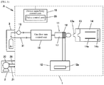
- ICP mass analysis device 100 mainly comprises a plasma torch 11, a high frequency power supply 12, a sample introduction unit 13, a mass analysis unit 14 comprising a mass analyzer, a gas flow rate control unit 15, and a device main body control unit 16, which make up a device main body unit 1.
- a cooling water system 2 and an Ar gas supply system 3, which are necessary when using the ICP mass analysis device 100, are furthermore connected to the device main body unit 1.
- the device main body unit 1 of the ICP mass analysis device 100 will be described in detail.
- the gas flow rate control unit 15 performs flow rate control of sample gas supplied from a nebulizer 19, Ar gas for plasma generation supplied via gas pipe 31 from the Ar gas supply system 3, and the like.
- the plasma torch 11 comprises a multiwall cylindrical reaction tube 17 to which plasma gas (Ar gas) and sample gas are supplied under flow rate control by the gas flow rate control unit 15, and a high frequency coil 18 wound onto the outer circumference of the reaction tube 17.
- the high frequency power supply 12 is connected to a high frequency coil 18, and plasma is generated to ionize the sample gas by applying high frequency voltage to the high frequency coil 18 in a state where plasma gas and sample gas have been introduced into the plasma torch 11.
- the sample introduction unit 13 is kept in a reduced pressure state by means of a vacuum pump (not illustrated) and is designed to draw in ions of the sample, which has been ionized by the plasma torch 11, along the central axis of a sampling cone 13a through a sample introduction orifice.
- the mass analysis unit 14 is maintained at a higher vacuum than the sample introduction unit 13, and performs mass separation of the sample ions, which have been draw in from the sample introduction unit 13, by means of a quadrupole 14a or the like, and further performs mass analysis by means of an ion detector 14b.
- the device main body control unit 16 is composed of a computer device comprising an input device (keyboard, mouse, etc.), display device (liquid crystal panel, etc.) and input/output interface, and performs configuration, command input and control of the various units of device main body unit 1, and also performs processing of data detected by the ion detector 14b.
- the reaction tube 17 of the plasma torch 11 which generates plasma is brought to a high temperature through induction heating, and in addition to that, the sample introduction unit 13 located opposite the plasma torch 11, the high frequency coil 18 and the high frequency power supply board 12a contained within the high frequency power supply 12 also reach a high temperature.
- cooling is required for the sample introduction unit 13, high frequency coil 18 and high frequency power supply 12, and cooling water is supplied from a cooling water system 2 in order to prevent corrosion and melting of the copper sampling cone 13a of the sample introduction unit 13 and of the copper high frequency coil 18, and to prevent breakdown due to heat generation of the high frequency power supply board 12a contained within the high frequency power supply 12.
- FIG. 7 is a drawing illustrating the piping system of cooling water system 2 and Ar gas supply system 3.
- the water-cooling piping of the cooling water system 2 is connected from a chiller (water source) 20 having a circulation pump which feeds cooling water, via a flow passage 21 to a master valve V0.
- the downstream side of the master valve V0 is connected to a flow passage 22, and the flow passage 22 branches in two and is connected to a first intermediate valve V2 and a second intermediate valve V3.
- a flow passage (bypass flow passage) 23 leading to the high frequency power supply 12 is connected to the first intermediate valve V2.
- a flow passage (high frequency power supply cooling flow passage) 24 for cooling the high frequency power supply 12 (high frequency power supply board 12a) is connected to the second intermediate valve V3.
- Flow passage (bypass flow passage) 23 and flow passage (high frequency power supply cooling flow passage) 24 are used by switching between them so as to prevent condensation from forming on the high frequency power supply 12, and are controlled such that the flow passage 24 side is opened when the high frequency power supply is in an ON state and requires cooling, and the flow passage 23 side is opened when the high frequency power supply is in an OFF state and does not require cooling.
- This flow passage switching control is performed by the device main body control unit 16 in a manner interlocked with the turning on and off of the high frequency power supply 12, with control being performed such that when one is opened, the other is closed, so that cooling water is always flowing.
- Flow passage 23 and flow passage 24 merge into flow passage 25, which then again branches into two and is connected to a flow passage (sample introduction unit cooling flow passage) 26 which cools the sample introduction unit 13 and a flow passage (high frequency coil cooling flow passage) 27 which cools the high frequency coil 18.
- sample introduction unit cooling flow passage which cools the sample introduction unit 13
- high frequency coil cooling flow passage which cools the high frequency coil 18.
- cooled structures The portions of device main body unit 1 which require cooling by the cooling water system 2 will be referred to as "cooled structures.”
- cooled structures consisting of the high frequency power supply 12, sample introduction unit 13 and high frequency coil 18, in the sampling cone 13a of the sample introduction unit 13, the orifice diameter of the central sample introduction orifice gradually widens due to aging degradation, which has an effect on analysis results, so the sampling cone 13a is made replaceable as a consumable part.
- FIG. 8 is a simplified cross-sectional view illustrating the sample introduction unit 13.
- the sampling cone 13a is integrally mounted on the outer surface side of cooling jacket 13b, and the inner surface side of the cooling jacket 13b is removably secured across a seal (not illustrated) so as to make the interface with the sample introduction unit main body 13c liquid-tight.
- a cooling flow passage 13d through which cooling water flows is formed in the cooling jacket 13b, and cooling water is supplied via a connecting flow passage 13e provided in the sample introduction unit main body 13c.
- the sampling cone 13a When the sampling cone 13a is to be replaced, the replacement is made from the cooling jacket 13b, and thus when the cooling jacket 13b is detached from the sample introduction unit main body 13c, the cooling water flow passage is opened at the interface between the connecting flow passage 13e and cooling flow passage 13d.
- cooling jacket 13b If the cooling jacket 13b is to be detached in order to replace the sampling cone 13a after cooling water has been fed into the cooling water system 2, it is necessary to stop the supply of water by closing the master valve V0, and to perform purging in order to drain the residual water remaining in the various flow passages past the master valve V0.
- a flow passage for supplying purge gas is formed in the cooling water system 2.
- a purge gas flow passage 32 is formed, which branches off from the middle of the Ar gas flow passage 31 of the Ar gas supply system 3 and is connected at merging point G to the flow passage 22 downstream of the master valve V0 of the cooling water system 2.
- a purge valve V1 is provided in the purge gas flow passage 32, and a check valve GV which prevents cooling water backflow is interposed.
- the master valve V0 is closed, after which the purge valve V1, first intermediate valve V2 and second intermediate valve V3 are all opened simultaneously, residual water is drained by introducing Ar gas from purge gas flow passage 32 into flow passages 22 through 28, and then the cooling jacket 13b is removed.
- Similar Ar gas purging is also performed when performing maintenance operations of the cooling water system 2 besides the sample introduction unit 13. Furthermore, a similar draining operation using Ar gas purging is performed not just during maintenance operations but also in order to prevent corrosion due to residual water when the device is stopped for a long period of time.
- Patent Literature 1 Japanese Unexamined Patent Application Publication 2014-85268
- the water cooling piping of the cooling water system 2 has a large pipe diameter and relatively low pipe resistance, so if purging with Ar gas is continued in order to drain the residual water, the amount of Ar gas consumption will become extremely high.
- the same Ar gas that is used for purging the cooling water system 2 is also used in the ICP mass analysis device 100 as the plasma gas (Ar gas), as the carrier gas for nebulizing the sample, etc., and is supplied via the Ar gas supply system 3 from an Ar gas source consisting of a single gas bottle (or liquid bottle).
- the Ar gas source is in nearly all cases used not just for a single ICP mass analysis device but is rather shared among multiple devices (other analytical devices, film growing devices, etc.).
- the Ar gas source of the Ar gas supply system 3 may be set up to supply Ar gas via an Ar gas flow passage 31 not just to the ICP mass analysis device (ICP-MS) 100 but also to a second ICP-MS 101, another analytical device 102, film forming device 103, etc.
- ICP-MS ICP mass analysis device
- the Ar gas source of the Ar gas supply system 3 may be set up to supply Ar gas via an Ar gas flow passage 31 not just to the ICP mass analysis device (ICP-MS) 100 but also to a second ICP-MS 101, another analytical device 102, film forming device 103, etc.
- Ar gas supply pressure which is normally maintained by means of a regulator at 480 KPa may drop to 400 KPa or less.
- the ICP mass analysis device of the present invention made to resolve the aforementioned problem, comprises: a device main body unit which supplies Ar gas for plasma generation and sample gas, via a gas flow rate control unit which controls gas flow rate, to a reaction tube of a plasma torch, ionizes the sample gas by applying a high frequency voltage from a high frequency power supply to a high frequency coil of said plasma torch, and draws in generated sample ions through a sample introduction unit to a mass analyzer to perform mass analysis; a cooling water system in which water cooling piping is connected as a flow passage to cooled structures which require cooling, including said high frequency power supply, said high frequency coil and said sample introduction unit, and which supplies cooling water from a water source to said cooled structures; and an Ar gas supply system in which gas piping is connected as a flow passage to said gas flow rate control unit and which supplies Ar gas from an Ar gas source; wherein, in said cooling water system, there is provided a master valve (V0) which is connected as a flow passage on the upstream side of said water cooling piping
- the valve control unit when draining of residual water of the cooling water system is to be performed for maintenance operations, etc., the valve control unit closes the master valve and places the purge valve into an open state to feed purge gas into the cooling water piping via the purge gas flow passage, at which time the valve control unit performs control whereby the intermediate valve is intermittently opened and closed.
- a pipe resistance comprising a pipe of the same diameter as or narrower diameter than the pipe diameter of the purge gas flow passage.
- the present invention by ensuring adequate time for accumulating pressure of Ar gas in accordance with the magnitude of pipe resistance in the flow passage up to the intermediate valve when the purge valve has been placed into an open state, the pressure of Ar gas accumulated upstream of the intermediate valve can be restored to about the same level as the pressure in the piping upstream of the purge valve, so even if the pipe resistance is increased, the operation of purging residual water can be effectively performed with the accumulated pressure.
- the water cooling piping of the cooling water system branches, downstream of the merging point of the purge gas flow passage, into a bypass flow passage having a first intermediate valve, and a high frequency power supply cooling flow passage to which a second intermediate valve and the high frequency power supply are connected as flow passages in series in that order;
- the sample introduction unit and the high frequency coil are connected as flow passages downstream of the bypass flow passage and the high frequency power supply cooling flow passage;
- the valve control unit when performing intermittent purge control, performs control whereby the first intermediate valve and the second intermediate valve are simultaneously placed into an open state, and the bypass flow passage and high frequency power supply cooling passage are simultaneously purged.
- valve control unit when performing intermittent purge control, performs control whereby the first intermediate valve and second intermediate valve are alternately placed into an open state one at a time, and the bypass flow passage and high frequency power supply cooling flow passage are purged one at a time.
- the flow passage of the cooling water system is connected so as to branch into a bypass flow passage and high frequency power supply cooling passage, a first intermediate valve is arranged in the bypass flow passage, and a second intermediate valve and the high frequency power supply are arranged in the high frequency power supply cooling flow passage.
- This first intermediate valve and second intermediate valve are configured such that when the high frequency power supply is off, the first intermediate valve is opened and the second intermediate valve is closed, and when the high frequency power supply is on, the first intermediate valve is closed and the second intermediate valve is opened, so that only one of the flow passages is in an open state and has cooling water flowing through it, thereby preventing the occurrence of condensation.
- the first intermediate valve and second intermediate valve that are used for switching the flow passage in interlocking fashion with the turning on and off of the high frequency power supply for the purpose of preventing condensation are also utilized for pressure accumulation for the purpose of draining residual water.
- valve control unit when the valve control unit performs intermittent purge control, control is performed whereby the first intermediate valve and second intermediate valve are simultaneously placed into an open state, and the bypass flow passage and high frequency power supply cooling flow passage are simultaneously purged.
- intermittent purge control when performing intermittent purge control, the valve control unit performs control whereby the first intermediate valve and second intermediate valve are alternately placed into an open state one at a time.
- FIG. 1 is a drawing illustrating the device configuration of an ICP mass analysis device A according to the present invention
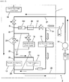
- FIG. 2 is a drawing illustrating the piping system of the cooling water system and Ar gas supply system 3 in the ICP mass analysis device A of FIG. 1 .
- constituent parts which are the same as in the conventional ICP mass analysis device 100 described in FIGS. 6 and 7 , the same reference symbols will be assigned and a portion of the description will be thus omitted.
- the device main body control unit 16 composed of a computer device as in the conventional ICP mass analysis device 100, is provided with a valve control unit 35 which performs execution of a valve control program which implements Ar gas purging based on opening and closing of a master valve V0, purge valve V1, first intermediate valve V2 and second intermediate valve V3.
- This valve control unit 35 when draining of the cooling water system 2 is to be performed, as a maintenance mode, performs intermittent purge control in which the master valve V0, purge valve V1, first intermediate valve V2 and second intermediate valve V3 are operated according to an operation flow as described below.
- a pipe resistance 36 which restricts inflow of gas is provided in the purge gas flow passage 32 downstream of the purge valve V1.
- the pipe resistance 36 is selected to have a magnitude of resistance sufficient to prevent sudden pressure fluctuation upstream of the purge valve V1 when the purge valve V1 is opened.
- a pipe with a narrower inside diameter of 0.5 mm is connected as a (coiled) pipe resistance 36 with a length of 1 m, thereby increasing the pipe resistance of the purge gas flow passage 32.
- pressure accumulation time T the time required for pressure accumulation in the intermittent purge control described above
- opening time F the time required for pressure accumulation in the intermittent purge control described above
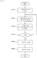
- FIG. 3 is a flow chart explaining an example of the gas purging operation flow using the valve control unit 35 of the ICP mass analysis device A.
- the parameter n which counts the number of purges is set to the initial value 0, the master valve V0 closes, and the first intermediate valve V2 and second intermediate valve V3 are closed nearly simultaneously. It will be noted that the purge valve V1 is closed to begin with (ST101).
- the purge valve V1 is opened and the open state is maintained until a preset pressure accumulation time T (10 seconds) elapses.
- a preset pressure accumulation time T 10 seconds
- the Ar gas of the purge gas flow passage 32 is accumulated until its pressure reaches the same level as the pressure upstream of the purge valve V1 (ST102).
- the first time since cooling water remains downstream of the check valve GV, by way of exception, Ar gas is accumulated in the pipe only up to the check valve GV, but in the second and subsequent pressure accumulation described below, pressure accumulation occurs also downstream of the check valve GV.
- the first intermediate valve V2 and second intermediate valve V3 are opened for a preset opening time F (5 seconds) to perform purging.
- the purge valve V1 is maintained in an open state, and Ar gas which has accumulated in the purge gas flow passage 32 is released and flows downstream, draining the residual water in the downstream direction.
- 1 is added to the purge count parameter n (ST103).
- the current purge count is checked on the basis of the parameter n (ST104). If the purge count parameter n is less than 5, the processing of ST102 through ST104 is repeated.
- the first intermediate valve V2 and second intermediate valve V3 are then also closed (ST106). Device operation is thereby completed.
- draining can be efficiently carried out through gas purging while reducing the consumption of Ar gas.
- FIG. 4 is a flow chart explaining another example of the gas purge operation flow using the valve control unit 35 of the ICP mass analysis device A.
- the difference from "operation flow - 1" described above is that the first intermediate valve V2 and second intermediate valve V3 are alternately opened and closed in order to carefully purge flow passage (bypass flow passage) 23 and flow passage (high frequency power supply cooling flow passage) 24 one by one.
- the operation in this case is as follows.
- the parameter n which counts the number of purges is set to the initial value 0, the master valve V0 closes, and the first intermediate valve V2 and second intermediate valve V3 are closed nearly simultaneously. It will be noted that the purge valve V1 is closed to begin with (ST201).
- the purge valve V1 is opened and the open state is maintained until a preset pressure accumulation time T (10 seconds) elapses.
- a preset pressure accumulation time T 10 seconds
- the Ar gas of the purge gas flow passage 32 is accumulated until its pressure reaches the same level as the pressure upstream of the purge valve V1 (ST202).
- the first time since cooling water remains downstream of the check valve GV, by way of exception, Ar gas is accumulated in the pipe only up to the check valve GV, but in the second and subsequent pressure accumulation described below, pressure accumulation occurs also downstream of the check valve GV.
- the first intermediate valve V2 is opened for a preset opening time F (5 seconds) to perform purging.
- the purge valve V1 is maintained in an open state, while the master valve V0 and second intermediate valve V3 are maintained in a closed state.
- the Ar gas which has accumulated in the purge gas flow passage 32 is released and flows downstream, draining the residual water in the downstream direction.
- 1 is added to the purge count parameter n (ST203).
- the purge valve V1 remaining open, the first intermediate valve V2 is closed, and the open state is maintained until a preset pressure accumulation time T (10 seconds) elapses.
- the second intermediate valve V3 is opened for a preset opening time F (5 seconds) and purging is performed.
- the purge valve V1 is maintained in an open state, while the master valve V0 and first intermediate valve V2 are maintained in a closed state.
- the Ar gas which has accumulated in the purge gas flow passage 32 is released and flows downstream, draining the residual water in the downstream direction.
- the purge count parameter n remains unchanged at this time (ST205).
- the current purge count is checked on the basis of the parameter n (ST206). If the purge count parameter n is less than 5, the processing of ST202 through ST205 is repeated.
- the first intermediate valve V2 and second intermediate valve V3 are then also closed (ST208). Device operation is thereby completed.
- draining can be efficiently carried out through gas purging while reducing the consumption of Ar gas.
- the master valve V0 closes, and the first intermediate valve V2 and the second intermediate valve V3 are closed nearly simultaneously. It will be noted that the purge valve V1 is closed to begin with (ST301).
- the purge valve V1, first intermediate valve V2 and second intermediate valve V3 are opened simultaneously, and the open state is maintained until a preset opening time F (for example, 30 seconds) elapses (ST302).
- the master valve V0 is maintained in a closed state.
- Ar gas flows in continuously, but the inflow of gas is restricted due to the existence of the pipe resistance 36, so the supply pressure does not drop significantly, making it possible to prevent adverse effects due to pressure fluctuation upstream of the purge valve V1.
- a pipe resistance 36 was provided in the purge gas flow passage 32 to reduce pressure fluctuation on the upstream side, but if instead no pipe resistance 36 is provided and only intermittent purge control is performed using the valve control unit 35, intermittent pressure fluctuation of upstream supply pressure will occur, but this is still effective because the magnitude of supply pressure fluctuation can be reduced as compared to the free-flowing state of the prior art.
- the present invention can be employed for ICP mass analysis devices.
Landscapes
- Chemical & Material Sciences (AREA)
- Analytical Chemistry (AREA)
- Physics & Mathematics (AREA)
- Engineering & Computer Science (AREA)
- Plasma & Fusion (AREA)
- Other Investigation Or Analysis Of Materials By Electrical Means (AREA)
- Electron Tubes For Measurement (AREA)
- Chemical Kinetics & Catalysis (AREA)
- Electrochemistry (AREA)
- Health & Medical Sciences (AREA)
- Life Sciences & Earth Sciences (AREA)
- Biochemistry (AREA)
- General Health & Medical Sciences (AREA)
- General Physics & Mathematics (AREA)
- Immunology (AREA)
- Pathology (AREA)
- Sampling And Sample Adjustment (AREA)
Applications Claiming Priority (2)
| Application Number | Priority Date | Filing Date | Title |
|---|---|---|---|
| JP2015251434 | 2015-12-24 | ||
| PCT/JP2016/068762 WO2017110118A1 (fr) | 2015-12-24 | 2016-06-24 | Spectromètre de masse icp |
Publications (2)
| Publication Number | Publication Date |
|---|---|
| EP3396368A1 true EP3396368A1 (fr) | 2018-10-31 |
| EP3396368A4 EP3396368A4 (fr) | 2019-08-14 |
Family
ID=59089925
Family Applications (1)
| Application Number | Title | Priority Date | Filing Date |
|---|---|---|---|
| EP16878021.1A Withdrawn EP3396368A4 (fr) | 2015-12-24 | 2016-06-24 | Spectromètre de masse icp |
Country Status (5)
| Country | Link |
|---|---|
| US (1) | US10354853B2 (fr) |
| EP (1) | EP3396368A4 (fr) |
| JP (1) | JP6512307B2 (fr) |
| CN (1) | CN108474761B (fr) |
| WO (1) | WO2017110118A1 (fr) |
Families Citing this family (5)
| Publication number | Priority date | Publication date | Assignee | Title |
|---|---|---|---|---|
| CN110010515A (zh) * | 2018-01-05 | 2019-07-12 | 北京北方华创微电子装备有限公司 | 射频电源冷却装置和方法、半导体加工设备 |
| CN115176153B (zh) * | 2020-03-19 | 2025-03-07 | 株式会社日立高新技术 | 液相色谱仪装置以及液相色谱仪装置的气泡去除方法 |
| CN112635291A (zh) * | 2020-12-24 | 2021-04-09 | 北京瑞蒙特科技有限公司 | 一种真空离子阱质谱仪系统 |
| WO2023177736A1 (fr) * | 2022-03-15 | 2023-09-21 | Elemental Scientific, Inc. | Système de purge atmosphérique et procédé de traitement d'échantillon d'ablation laser |
| US20230408542A1 (en) * | 2022-06-09 | 2023-12-21 | Elemental Scientific, Inc. | Automated inline nanoparticle standard material addition |
Family Cites Families (15)
| Publication number | Priority date | Publication date | Assignee | Title |
|---|---|---|---|---|
| US5383019A (en) * | 1990-03-23 | 1995-01-17 | Fisons Plc | Inductively coupled plasma spectrometers and radio-frequency power supply therefor |
| JP3123843B2 (ja) * | 1992-12-17 | 2001-01-15 | 日本電子株式会社 | プラズマフレームを用いた試料気化装置 |
| FI93174C (fi) * | 1993-12-31 | 1995-03-10 | Paul Ek | Reaktiokammio ja sen käyttöön pohjautuva uusi määritysmenetelmä |
| EP0799408B1 (fr) * | 1994-12-20 | 2003-03-19 | Varian Australia Pty. Ltd. | Spectrometre pourvu d'un dispositif de limitation de decharge |
| US6239038B1 (en) * | 1995-10-13 | 2001-05-29 | Ziying Wen | Method for chemical processing semiconductor wafers |
| US6222186B1 (en) * | 1998-06-25 | 2001-04-24 | Agilent Technologies, Inc. | Power-modulated inductively coupled plasma spectrometry |
| DE60223710T2 (de) * | 2001-11-15 | 2008-10-30 | L'Air Liquide, S.A. pour l'Etude et l'Exploitation des Procédés Georges Claude | Flüssigkeitsversorgungsvorrichtung mit reinigungsfunktion |
| JP3800621B2 (ja) * | 2002-01-18 | 2006-07-26 | 株式会社島津製作所 | Icp分析装置 |
| US7742167B2 (en) * | 2005-06-17 | 2010-06-22 | Perkinelmer Health Sciences, Inc. | Optical emission device with boost device |
| US7518108B2 (en) * | 2005-11-10 | 2009-04-14 | Wisconsin Alumni Research Foundation | Electrospray ionization ion source with tunable charge reduction |
| CN102375022A (zh) * | 2011-10-09 | 2012-03-14 | 北京纳克分析仪器有限公司 | 激光烧蚀电感耦合等离子体质谱原位统计分布分析系统 |
| CA2884625A1 (fr) * | 2012-09-14 | 2014-03-20 | Stewart Nicholson | Systeme de detection d'humidite |
| JP6048068B2 (ja) * | 2012-10-25 | 2016-12-21 | 株式会社島津製作所 | プラズマ用高周波電源及びそれを用いたicp発光分光分析装置 |
| JP6096105B2 (ja) * | 2013-12-20 | 2017-03-15 | 三菱日立パワーシステムズ株式会社 | チャー回収システムおよびチャー搬送方法 |
| CN104602429B (zh) * | 2015-01-30 | 2017-01-25 | 清华大学 | 一种暖等离子体发生器 |
-
2016
- 2016-06-24 WO PCT/JP2016/068762 patent/WO2017110118A1/fr not_active Ceased
- 2016-06-24 JP JP2017557724A patent/JP6512307B2/ja active Active
- 2016-06-24 CN CN201680076005.XA patent/CN108474761B/zh active Active
- 2016-06-24 EP EP16878021.1A patent/EP3396368A4/fr not_active Withdrawn
- 2016-06-24 US US16/065,496 patent/US10354853B2/en active Active
Also Published As
| Publication number | Publication date |
|---|---|
| US10354853B2 (en) | 2019-07-16 |
| JPWO2017110118A1 (ja) | 2018-09-27 |
| CN108474761A (zh) | 2018-08-31 |
| US20190013192A1 (en) | 2019-01-10 |
| CN108474761B (zh) | 2020-07-17 |
| JP6512307B2 (ja) | 2019-05-15 |
| WO2017110118A1 (fr) | 2017-06-29 |
| EP3396368A4 (fr) | 2019-08-14 |
Similar Documents
| Publication | Publication Date | Title |
|---|---|---|
| EP3396368A1 (fr) | Spectromètre de masse icp | |
| JP6488294B2 (ja) | 平均流量の減少を可能にする質量分析計の入口 | |
| CN105579844B (zh) | 气相色谱质量分析装置 | |
| JP6734061B2 (ja) | プラズマ分光分析装置 | |
| WO2010134761A2 (fr) | Laveur de gaz plasma | |
| KR20170093975A (ko) | 온라인 이송된 분석 시료의 분석 시스템 | |
| US8236091B2 (en) | Fluid separation method and fluid separation apparatus | |
| US20150219532A1 (en) | Sample introduction device | |
| CN102348644B (zh) | 超纯水制造设备及超纯水的监测方法 | |
| US9343283B1 (en) | Internal standardization with enriched stable isotopes and cool plasma ICPMS | |
| TWI702631B (zh) | 控制由經組態以將電力供應至一氣體處理系統中之一電漿炬之一電力供應器輸出之電力之方法及由一處理器執行之電腦程式 | |
| JP5304749B2 (ja) | 真空分析装置 | |
| KR100416204B1 (ko) | 가스 공급장치 및 가스 치환방법 | |
| JP2022527350A5 (fr) | ||
| CN109844519B (zh) | 气相色谱仪 | |
| WO2013190277A2 (fr) | Procédé et appareil de commande d'alimentation en ions | |
| TWI810765B (zh) | 處理液供應裝置以及處理液供應裝置的固體去除方法 | |
| US20180228014A1 (en) | Control of power supplied to a plasma torch to compensate for changes at an electrode | |
| KR101367819B1 (ko) | 플라즈마 공정챔버의 잔류가스 분석장치 | |
| CN121497970B (zh) | 一种色谱仪氢气闭环循环控制装置及方法 | |
| JPWO2019053850A1 (ja) | 液体クロマトグラフ | |
| CN117373895A (zh) | 用于改进试剂气体系统的纯度的周期定时器 | |
| KR20070033114A (ko) | 반도체 제조설비 및 그 제어방법 | |
| WO2021111593A1 (fr) | Dispositif d'introduction d'échantillon |
Legal Events
| Date | Code | Title | Description |
|---|---|---|---|
| STAA | Information on the status of an ep patent application or granted ep patent |
Free format text: STATUS: THE INTERNATIONAL PUBLICATION HAS BEEN MADE |
|
| PUAI | Public reference made under article 153(3) epc to a published international application that has entered the european phase |
Free format text: ORIGINAL CODE: 0009012 |
|
| STAA | Information on the status of an ep patent application or granted ep patent |
Free format text: STATUS: REQUEST FOR EXAMINATION WAS MADE |
|
| 17P | Request for examination filed |
Effective date: 20180724 |
|
| AK | Designated contracting states |
Kind code of ref document: A1 Designated state(s): AL AT BE BG CH CY CZ DE DK EE ES FI FR GB GR HR HU IE IS IT LI LT LU LV MC MK MT NL NO PL PT RO RS SE SI SK SM TR |
|
| AX | Request for extension of the european patent |
Extension state: BA ME |
|
| DAV | Request for validation of the european patent (deleted) | ||
| DAX | Request for extension of the european patent (deleted) | ||
| A4 | Supplementary search report drawn up and despatched |
Effective date: 20190717 |
|
| RIC1 | Information provided on ipc code assigned before grant |
Ipc: H01J 49/10 20060101ALI20190711BHEP Ipc: G01N 27/62 20060101AFI20190711BHEP |
|
| GRAP | Despatch of communication of intention to grant a patent |
Free format text: ORIGINAL CODE: EPIDOSNIGR1 |
|
| STAA | Information on the status of an ep patent application or granted ep patent |
Free format text: STATUS: GRANT OF PATENT IS INTENDED |
|
| INTG | Intention to grant announced |
Effective date: 20200403 |
|
| STAA | Information on the status of an ep patent application or granted ep patent |
Free format text: STATUS: THE APPLICATION IS DEEMED TO BE WITHDRAWN |
|
| 18D | Application deemed to be withdrawn |
Effective date: 20200814 |