EP3398708B1 - Appareil de soudage par friction-malaxage, dispositif de commande de soudage par friction-malaxage et procédé de soudage par friction-malaxage - Google Patents
Appareil de soudage par friction-malaxage, dispositif de commande de soudage par friction-malaxage et procédé de soudage par friction-malaxage Download PDFInfo
- Publication number
- EP3398708B1 EP3398708B1 EP18165079.7A EP18165079A EP3398708B1 EP 3398708 B1 EP3398708 B1 EP 3398708B1 EP 18165079 A EP18165079 A EP 18165079A EP 3398708 B1 EP3398708 B1 EP 3398708B1
- Authority
- EP
- European Patent Office
- Prior art keywords
- friction stir
- welding
- cooling device
- gradual cooling
- stir welding
- Prior art date
- Legal status (The legal status is an assumption and is not a legal conclusion. Google has not performed a legal analysis and makes no representation as to the accuracy of the status listed.)
- Not-in-force
Links
Images


Classifications
-
- B—PERFORMING OPERATIONS; TRANSPORTING
- B23—MACHINE TOOLS; METAL-WORKING NOT OTHERWISE PROVIDED FOR
- B23K—SOLDERING OR UNSOLDERING; WELDING; CLADDING OR PLATING BY SOLDERING OR WELDING; CUTTING BY APPLYING HEAT LOCALLY, e.g. FLAME CUTTING; WORKING BY LASER BEAM
- B23K20/00—Non-electric welding by applying impact or other pressure, with or without the application of heat, e.g. cladding or plating
- B23K20/12—Non-electric welding by applying impact or other pressure, with or without the application of heat, e.g. cladding or plating the heat being generated by friction; Friction welding
- B23K20/122—Non-electric welding by applying impact or other pressure, with or without the application of heat, e.g. cladding or plating the heat being generated by friction; Friction welding using a non-consumable tool, e.g. friction stir welding
- B23K20/123—Controlling or monitoring the welding process
- B23K20/1235—Controlling or monitoring the welding process with temperature control during joining
-
- B—PERFORMING OPERATIONS; TRANSPORTING
- B23—MACHINE TOOLS; METAL-WORKING NOT OTHERWISE PROVIDED FOR
- B23K—SOLDERING OR UNSOLDERING; WELDING; CLADDING OR PLATING BY SOLDERING OR WELDING; CUTTING BY APPLYING HEAT LOCALLY, e.g. FLAME CUTTING; WORKING BY LASER BEAM
- B23K20/00—Non-electric welding by applying impact or other pressure, with or without the application of heat, e.g. cladding or plating
- B23K20/12—Non-electric welding by applying impact or other pressure, with or without the application of heat, e.g. cladding or plating the heat being generated by friction; Friction welding
- B23K20/122—Non-electric welding by applying impact or other pressure, with or without the application of heat, e.g. cladding or plating the heat being generated by friction; Friction welding using a non-consumable tool, e.g. friction stir welding
- B23K20/123—Controlling or monitoring the welding process
- B23K20/124—Controlling or monitoring the welding process at the beginning or at the end of a weld
-
- B—PERFORMING OPERATIONS; TRANSPORTING
- B23—MACHINE TOOLS; METAL-WORKING NOT OTHERWISE PROVIDED FOR
- B23K—SOLDERING OR UNSOLDERING; WELDING; CLADDING OR PLATING BY SOLDERING OR WELDING; CUTTING BY APPLYING HEAT LOCALLY, e.g. FLAME CUTTING; WORKING BY LASER BEAM
- B23K20/00—Non-electric welding by applying impact or other pressure, with or without the application of heat, e.g. cladding or plating
- B23K20/12—Non-electric welding by applying impact or other pressure, with or without the application of heat, e.g. cladding or plating the heat being generated by friction; Friction welding
- B23K20/122—Non-electric welding by applying impact or other pressure, with or without the application of heat, e.g. cladding or plating the heat being generated by friction; Friction welding using a non-consumable tool, e.g. friction stir welding
- B23K20/123—Controlling or monitoring the welding process
-
- B—PERFORMING OPERATIONS; TRANSPORTING
- B23—MACHINE TOOLS; METAL-WORKING NOT OTHERWISE PROVIDED FOR
- B23K—SOLDERING OR UNSOLDERING; WELDING; CLADDING OR PLATING BY SOLDERING OR WELDING; CUTTING BY APPLYING HEAT LOCALLY, e.g. FLAME CUTTING; WORKING BY LASER BEAM
- B23K20/00—Non-electric welding by applying impact or other pressure, with or without the application of heat, e.g. cladding or plating
- B23K20/12—Non-electric welding by applying impact or other pressure, with or without the application of heat, e.g. cladding or plating the heat being generated by friction; Friction welding
- B23K20/122—Non-electric welding by applying impact or other pressure, with or without the application of heat, e.g. cladding or plating the heat being generated by friction; Friction welding using a non-consumable tool, e.g. friction stir welding
- B23K20/1245—Non-electric welding by applying impact or other pressure, with or without the application of heat, e.g. cladding or plating the heat being generated by friction; Friction welding using a non-consumable tool, e.g. friction stir welding characterised by the apparatus
-
- B—PERFORMING OPERATIONS; TRANSPORTING
- B23—MACHINE TOOLS; METAL-WORKING NOT OTHERWISE PROVIDED FOR
- B23K—SOLDERING OR UNSOLDERING; WELDING; CLADDING OR PLATING BY SOLDERING OR WELDING; CUTTING BY APPLYING HEAT LOCALLY, e.g. FLAME CUTTING; WORKING BY LASER BEAM
- B23K20/00—Non-electric welding by applying impact or other pressure, with or without the application of heat, e.g. cladding or plating
- B23K20/26—Auxiliary equipment
-
- C—CHEMISTRY; METALLURGY
- C21—METALLURGY OF IRON
- C21D—MODIFYING THE PHYSICAL STRUCTURE OF FERROUS METALS; GENERAL DEVICES FOR HEAT TREATMENT OF FERROUS OR NON-FERROUS METALS OR ALLOYS; MAKING METAL MALLEABLE, e.g. BY DECARBURISATION OR TEMPERING
- C21D9/00—Heat treatment, e.g. annealing, hardening, quenching or tempering, adapted for particular articles; Furnaces therefor
- C21D9/50—Heat treatment, e.g. annealing, hardening, quenching or tempering, adapted for particular articles; Furnaces therefor for welded joints
- C21D9/505—Cooling thereof
-
- B—PERFORMING OPERATIONS; TRANSPORTING
- B23—MACHINE TOOLS; METAL-WORKING NOT OTHERWISE PROVIDED FOR
- B23K—SOLDERING OR UNSOLDERING; WELDING; CLADDING OR PLATING BY SOLDERING OR WELDING; CUTTING BY APPLYING HEAT LOCALLY, e.g. FLAME CUTTING; WORKING BY LASER BEAM
- B23K2101/00—Articles made by soldering, welding or cutting
- B23K2101/18—Sheet panels
-
- C—CHEMISTRY; METALLURGY
- C21—METALLURGY OF IRON
- C21D—MODIFYING THE PHYSICAL STRUCTURE OF FERROUS METALS; GENERAL DEVICES FOR HEAT TREATMENT OF FERROUS OR NON-FERROUS METALS OR ALLOYS; MAKING METAL MALLEABLE, e.g. BY DECARBURISATION OR TEMPERING
- C21D1/00—General methods or devices for heat treatment, e.g. annealing, hardening, quenching or tempering
- C21D1/34—Methods of heating
- C21D1/42—Induction heating
-
- Y—GENERAL TAGGING OF NEW TECHNOLOGICAL DEVELOPMENTS; GENERAL TAGGING OF CROSS-SECTIONAL TECHNOLOGIES SPANNING OVER SEVERAL SECTIONS OF THE IPC; TECHNICAL SUBJECTS COVERED BY FORMER USPC CROSS-REFERENCE ART COLLECTIONS [XRACs] AND DIGESTS
- Y02—TECHNOLOGIES OR APPLICATIONS FOR MITIGATION OR ADAPTATION AGAINST CLIMATE CHANGE
- Y02P—CLIMATE CHANGE MITIGATION TECHNOLOGIES IN THE PRODUCTION OR PROCESSING OF GOODS
- Y02P10/00—Technologies related to metal processing
- Y02P10/25—Process efficiency
Definitions
- the present invention relates to friction stir welding apparatus, and a friction stir welding method according to the preamble of claims 1, 2 and 13 (see for example US 2014/027496 A1 ).
- FSW friction stir welding
- welding conditions the rotation speed and welding speed of a welding tool
- a conventional FSW apparatus retains the welding conditions thus set from the start to the end of the welding and controls the welding using these welding conditions.
- the present invention aims to provide a friction stir welding apparatus, a friction stir welding control device, and a friction stir welding method which can achieve high-quality friction stir welding.
- a friction stir welding apparatus of the present invention comprises: a friction stir welding tool that is held by an apparatus main body and welds a plurality of to-be-welded members to each other by friction stir; and/or a gradual cooling device that gradually cools a weld site of the to-be-welded members welded by the friction stir welding tool, and the apparatus main body includes a gradual cooling device welding direction movement driver that moves the gradual cooling device in a welding direction.
- the present invention can provide a friction stir welding apparatus, a friction stir welding control device, and a friction stir welding method which can achieve high-quality friction stir welding.
- FIG. 1 is a diagram schematically illustrating an example of a perspective view of the external appearance of an FSW apparatus 100A.
- the FSW apparatus 100A includes components such as a friction stir welding (FSW) tool 1A and a gradual cooling device 10.
- FSW friction stir welding
- the FSW tool 1A includes a welding tool 1 having a protrusion (also called a probe) 11, and a tool holder 2 that holds the welding tool 1.
- the FSW tool 1A is held by a housing 3 (an apparatus main body) that holds the tool holder 2 while allowing the tool holder 2 to rotate.
- the housing 3 is a cylindrical container and has a main axis motor 6 (see FIG. 3 ) and the like housed therein.
- the main axis motor 6 rotates the solid cylindrical tool holder 2 about its main axis 20.
- the main axis 20 is the center axis of the solid cylindrical tool holder 2.
- the housing 3 thus holding the welding tool 1 and the tool holder 2 is attached to a tip portion of an arm 4 of a machining tool or a multiaxis robot (not shown).
- the welding tool 1 is configured to be movable freely in both vertical directions and planar directions by driving of the arm 4 of the machining tool or multiaxis robot.
- the protrusion 11 of the welding tool 1 is shaped like an elongated pin extending along the center of the main axis 20 to be described later (see FIG. 2 ), and is often called a welding tool pin portion.
- the welding tool 1 held by the tool holder 2 rotates and presses its protrusion 11 onto a welding line 102, which is the border between the to-be-welded members 101a and 101b.
- the protrusion 11 is pressed in until the part of the bottom surface of the main body of the welding tool 1 excluding the protrusion 11 (a tool shoulder portion 12, see FIG. 2 ) comes into contact with the surfaces of the to-be-welded members 101a and 101b.
- temperatures of to-be-welded members 101a and 101b rise due to the friction heat generated by the rotation of the protrusion 11 and the tool shoulder portion 12 (see FIG. 2 ) in contact with the to-be-welded members 101a and 101b, causing a plastic flow phenomenon.
- the materials forming the to-be-welded members 101a and 101b experiencing the plastic flow phenomenon are stirred and mixed by the welding tool 1.
- the welding tool 1 is controlled so that the protrusion 11 moves along the welding line 102 while being pressed in the to-be-welded members 101a and 101b.
- the to-be-welded members 101a and 101b are welded to each other at their border portion.
- the gradual cooling device 10 is fixed to the housing 3 (the apparatus main body) via a fixation member 30.
- the fixation member 30 is formed of a plate-shaped member extending from the housing 3 in a direction opposite from the welding direction D.
- the gradual cooling device 10 is attached to the fixation member 30 on its surface facing the to-be-welded members 101a and 101b.
- the gradual cooling device 10 performs post-heating (or post-heat application) on a weld site S (a welded site) of the to-be-welded members 101a and 101b welded by the FSW tool 1A to prevent the weld site S from experiencing a rapid temperature drop or from being quenched.
- post-heating means heating the weld site S at temperatures that cause almost no alternation of the metallographic structure of the weld site S of the to-be-welded members 101a and 101b welded by the FSW tool 1A. Further, the heating is carried out at temperatures that do not alter the metallographic structure of the weld site welded by the FSW tool 1A.
- the gradual cooling device 10 is formed of a high-frequency heat source (a contactless heat source), which is a spirally-wound induction coil 10a.
- a high-frequency heat source a contactless heat source
- lines of magnetic force are generated to transverse the weld site S, causing eddy currents inside the weld site S.
- the eddy currents are converted to Joule heat, the weld site S produces heat and heats up.
- FIG. 2 is a diagram illustrating an example of a schematic block configuration of the FSW apparatus 100A according to this first example. Note that FIG. 2 shows not only the schematic longitudinal sectional structures of the welding tool 1, the tool holder 2, and the housing 3, but also devices and members associated with them.
- the housing 3 is a cylindrical container inside which the solid cylindrical tool holder 2 is held while being rotatable about the center axis (the main axis 20) of the solid cylinder via bearings 31. This rotation of the tool holder 2 is driven by the main axis motor 6 attached to the housing 3.
- the welding tool 1 is attached to a lower end portion of the tool holder 2 and is driven and rotated by the main axis motor 6 along with the tool holder 2.
- the welding tool 1 is shaped like a solid cylinder and is coaxial with the tool holder 2. On its bottom surface portion, the welding tool 1 is provided with the elongated, substantially solid cylindrical (pin-shaped) protrusion 11 which is coaxial with the tool holder 2. The part of the bottom surface portion of the welding tool 1 excluding the protrusion 11 is called the tool shoulder portion 12. Of these, the protrusion 11 is pressed in until the tool shoulder portion 12 comes into contact with the surface of the to-be-welded members 101a and 101b. Thus, the tool shoulder portion 12 functions to stop the protrusion 11 from being pressed in further. Also, in this event, the tool shoulder portion 12 pushes the to-be-welded members 101a and 101b, and rotates and slides on their surface. Friction heat produced by the rotation and sliding of the tool shoulder portion 12 heats up the part of the to-be-welded members 101a and 101b near the tool shoulder portion 12 and the protrusion 11, causing a plastic flow phenomenon.
- a control device 5A is configured with a general computer including an arithmetic processing device and a storage device (not shown), and controls the rotation speed of the main axis motor 6, the movement speed of a tool movement driving device 7 (a tool movement driver), and the amount of heat to be outputted from the gradual cooling device 10 to the weld site S.
- the tool movement driving device 7 corresponds to a machining center type FSW apparatus or a multiaxis robot type FSW apparatus having the arm 4 attached to the housing 3 in FIG. 1 .
- control device 5A has a heat amount controller 5a that controls the gradual cooling device 10 so that the weld site S may have a temperature similar to a post-welding temperature.
- a storage device of the control device 5A stores the following FSW control data.
- the FSW control data are formed by welding temperature, the rotation speed of the main axis motor, tool movement speed, and the like associated with the materials and plate thicknesses of the to-be-welded members 101a and 101b.
- an initial value, a stationary value #1, and a stationary value #2 are set, and for the tool movement speed, a stationary value #1 and a stationary value #2 are set.
- the initial value for the rotation speed of the main axis motor is an initial value for the speed at which the main axis motor 6 is to rotate when the protrusion 11 of the welding tool 1 is pressed into the to-be-welded members 101a and 101b.
- the stationary values #1 and #2 of the main axis motor rotation speed are data set as the rotation speed of the main axis motor 6 during welding
- the stationary values #1 and #2 of the tool movement speed are data set as the movement speed of the welding tool 1 during welding.
- These values are appropriate values determined in advance by experiment or simulation according to, for example, the materials and plate thicknesses of the to-be-welded members 101a and 101b.
- FIG. 3 is a longitudinal sectional view schematically illustrating how the protrusion of the welding tool is pressed into the to-be-welded members.
- the to-be-welded members 101a and 101b are placed on a backing member 110, and the protrusion 11 of the welding tool 1 is pressed into their border portion while rotating.
- the protrusion 11 is pressed to a depth where the tip portion thereof almost reaches the back surfaces of the to-be-welded members 101a and 101b while the tool shoulder portion 12 comes into contact with the front surfaces of the to-be-welded members 101a and 101b.
- the diameter, length, shape, and the like of the protrusion 11 of the welding tool 1 are determined typically according to the plate thicknesses and materials of the targets to be welded.
- the backing member 110 has high resistance to heat and has sufficient rigidity to withstand load in the tool axial direction.
- FIGs. 4A and 4B illustrate an example of how to-be-welded members made of different materials are welded to each other, FIG. 4A showing butt welding, FIG. 4B showing lap welding.
- the protrusion 11 of the welding tool 1 is pressed into a position such that the entire protrusion 11 is in the to-be-welded member 101c made of a material that softens at low temperatures, with the outer circumference of the protrusion 11 being in contact with the border of the to-be-welded members 101c and 101d.
- the protrusion 11 of the welding tool 1 is pressed into a position on the to-be-welded member 101c made of an aluminum alloy.
- the protrusion 11 of the welding tool 1 is pressed first into the to-be-welded member 101c made of a material that softens at low temperature until the tip of the protrusion 11 comes into contact with the to-be-welded member 101d.
- the to-be-welded members 101c and 101d in FIG. 4B may be made of the same material.
- the protrusion 11 of the welding tool 1 is preferably pressed into the lower to-be-welded member 101d as well beyond their border. This allows a friction stir region to be formed at their border portion, producing a rigid weld.
- FIG. 5 is a diagram illustrating the operation of the FSW apparatus according to the first example.
- the diagram shown to the left illustrates the FSW apparatus at the start of welding
- the diagram drawn in a chain double-dashed line illustrates the FSW apparatus at the end of welding
- the diagram shown to the right illustrates the FSW apparatus at the end of heating.
- the FSW apparatus is shown in a simplified form, and the solid line extending in the welding direction D from the right to the left in FIG. 5 is the welding line 102.
- the FSW apparatus 100A includes the gradual cooling device 10 fixed to the housing 3 (the apparatus main body) via the fixation member 30.
- the gradual cooling device 10 of this embodiment moves vertically as the FSW tool 1A moves vertically.
- the rotation center O1 of the FSW tool 1A (the main axis 20) and the gradual cooling device 10 (an end portion 10b thereof closer to the FSW tool 1A) are away from each other by a distance E.
- the distance E is a physical distance always created between the FSW tool 1A and the gradual cooling device 10.
- the gradual cooling device 10 is configured to output heat amount Q1 to heat a range R1 indicated with hatching.
- every position on the weld site S (see FIG. 1 ) formed from the start of welding to the end of welding is heated (gradually cooled) in the range R1.
- the vertically upward movement of the FSW apparatus 100A at the end of welding changes the distance between the gradual cooling device 10 and the to-be-welded members 101a and 101b (or the weld site S) since the gradual cooling device 10 moves vertically as the FSW tool 1A moves vertically.
- the heat amount Q1 which has been applied to the weld site S from the start of welding to the end of welding is now insufficient.
- heat amount Q2 which is larger than the heat amount Q1 is used to heat the weld site S for a distance ⁇ from the end of welding to the end of heating (the end of gradual cooling).
- the heat amount Q2 is one that achieves the same heat capacity as that applied to the weld site S by the heat amount Q1.
- the heat amount Q2 is one that causes the weld site S to be heated at the same temperature as when heated by the heat amount Q1.
- control device 5A controls the gradual cooling device 10 to change the heat amount Q1 to the heat amount Q2 from the end of welding to the end of heating, and the heating is continued until the position of the gradual cooling device 10 reaches the welding end position (distance ⁇ ).
- FIG. 6 shows the relation between the temperature of a weld site and the elapsed time since the end of welding in the FSW apparatus according to the first embodiment.
- the solid line indicates the present embodiment
- the broken line indicates a comparative example. Note that in the comparative example in FIG. 6 , the gradual cooling device 10 of the present embodiment is not provided, and the weld site is naturally cooled right after welding ends.
- the weld site S starts to naturally cool right after welding and experiences rapid cooldown, as shown with the broken line in FIG. 6 .
- a crack or the like occurs after the welding.
- the weld site S after the welding, the weld site S immediately undergoes gradual cooling (post-heating) by the gradual cooling device 10, and therefore the start of natural cooling can be delayed by the length of time Tm.
- the weld site S is maintained at a temperature similar to a post-welding temperature. After the time Tm passes, the temperature of the weld site S starts to drop at the start point P due to natural cooling.
- to-be-welded members 101a and 101b to employ in the present example are not limited to a combination of high-tensile strength steel plates, and may be any other combinations, such as a combination of an aluminum alloy and iron.
- the FSW apparatus 100A of the first example includes the FSW tool 1A that is held by the housing 3 and welds a plurality of to-be-welded members 101a and 101b to each other by friction stir, and the gradual cooling device 10 that gradually cools the weld site S of the to-be-welded members 101a and 101b welded by the FSW tool 1A.
- This allows the start point P of natural cooling of the weld site S to be delayed (see FIG. 6 ), and hence allows the weld site S to be of higher quality than when the gradual cooling (post-heating) is not carried out.
- the weld site S is thus post-heated by the gradual cooling device 10 to delay the start of natural cooling, high-quality friction stir welding can be achieved.
- the gradual cooling device 10 employs a contactless heat source which heats the weld site S without coming into contact with the weld site S. While use of a contact heat source may degrade welding quality by friction caused between the contact heat source and the weld site S, use of a contactless heat source does not cause friction with the weld site S, and thus helps prevent degradation in the welding quality.
- a high-frequency heat source is used as the contactless heat source. This allows the weld site S to be maintained at a temperature equal to or close to the temperature immediately after the welding (temperature that causes no metallographic alteration) with a contactless, simple configuration. Thus, further improvement in welding quality can be expected.
- the contactless heat source may alternatively be an optical heat source such as laser light, or other heat sources.
- Such an optical heat source can also post-heat the weld site S in a similar manner to a high-frequency heat source.
- the FSW apparatus 100A of the first example further includes the tool movement driving device 7 that moves the FSW tool 1A along the welding line 102, and the control device 5A (the heat amount controller 5a) that controls the amount of heat that the gradual cooling device 10 applies to the weld site S (see FIG. 2 ).
- the gradual cooling device 10 is fixed to the housing 3, and the control device 5A increases the amount of heat to apply to the weld site S when FSW tool 1A is moved away from the weld site S at the end of welding.
- the FSW tool 1A and the gradual cooling device 10 are configured to be physically away from each other in the welding direction D, all the regions welded by the FSW tool 1A can be gradually cooled.
- having fewer movable parts allows a simpler configuration of the FSW apparatus 100A and also enhances the reliability as a product.
- FIG. 7 is a diagram showing a schematic block configuration of an FSW apparatus according to a second example. Note that the same components as those in the first example are denoted by the same reference numerals as those used in the first example to omit repeated descriptions (the same applies to the following embodiments as well).
- an FSW apparatus 100B of the second example includes a gradual cooler axial movement driving device 8 (a gradual cooling device axial movement driver) that enables the gradual cooling device 10 to move vertically (i.e., the axial direction of the FSW tool 1A).
- a gradual cooler axial movement driving device 8 a gradual cooling device axial movement driver
- the gradual cooler axial movement driving device 8 is provided between the housing 3 and the fixation member 30 and configured to move the fixation member 30 vertically relative to the housing 3 to vertically move the gradual cooling device 10 fixed to the fixation member 30.
- the gradual cooler axial movement driving device 8 may be configured to be able to convert the rotational force of the electric motor to linear force for the gradual cooling device 10.
- the gradual coqler axial movement driving device 8 is electrically connected to a control device 5B, and when the FSW tool 1A moves away from the weld site S at the end of welding, controls and moves the gradual cooling device 10 toward the weld site S so that the distance between the gradual cooling device 10 and the weld site S may be the same as that before the end of welding.
- the control device 5B has a gradual cooler driving controller 5b (a gradual cooling device driving controller) that controls the gradual cooler axial movement driving device 8 that moves the gradual cooling device 10 vertically. This configuration eliminates the control for changing the amount of heat outputted from the gradual cooling device 10 like in the first Example useful for understanding the invention).
- FIG. 8 is a diagram illustrating the operation of the FSW apparatus according to the second example. Note that in FIG. 8 , the diagram to the left illustrates the FSW apparatus at the start of welding, the diagram drawn in a chain double-dashed line illustrates the FSW apparatus at the end of welding, and the diagram to the right illustrates the FSW apparatus at the end of heating.
- the gradual cooling device 10 moves vertically relative to the FSW tool 1A as the fixation member 30 fixed to the housing 3 (the apparatus main body) is moved vertically by the gradual cooler axial movement driving device 8.
- heating by the gradual cooling device 10 starts. Note that at the start of welding in FIG. 8 , the gradual cooling device 10 heats the range R1 indicated with hatching with the heat amount Q1.
- the upward movement of the FSW apparatus 100B at the end of welding changes the distance between the weld site S and the gradual cooling device 10.
- the gradual cooling device 10 is moved down by the gradual cooler axial movement driving device 8 for the distance ⁇ from the end of welding to the end of heating to make the distance between the weld site S and the gradual cooling device 10 the same as before the end of welding.
- the FSW tool 1A is raised X cm at the end of welding
- the gradual cooling device 10 is lowered X cm.
- the FSW apparatus 100B of the second example includes the tool movement driving device 7 that moves the FSW tool 1A along the welding line 102, the gradual cooler axial movement driving device 8 that moves the gradual cooling device 10 toward and away from the weld site S, and the gradual cooler driving controller 5b that controls the gradual cooler axial movement driving device 8.
- the gradual cooler driving controller 5b causes the gradual cooler axial movement driving device 8 to drive the gradual cooling device 10 toward the weld site S.
- This configuration only involves mechanical positional change of the gradual cooling device 10, and therefore the control by the control device 5B is simpler than the case of changing the amount heat from the gradual cooling device 10.
- the other configurations that are the same as those of the first example offer the same advantageous effects.
- FIG. 9 is a diagram showing a schematic configuration of an FSW apparatus according to a first embodiment of the present invention.
- an FSW apparatus 100C of the first embodiment includes a gradual cooler welding direction movement driving device 9 (a gradual cooling device welding direction movement driver) that moves the gradual cooling device 10 in the welding direction D.
- the gradual cooler welding direction movement driving device 9 is provided to a fixation member 32, and is capable of changing the distance E between the rotation center O1 of the FSW tool 1A (the main axis 20) and the gradual cooling device 10 (the end portion 10b thereof closer to the FSW tool 1A).
- Other configurations are the same as those in the first example.
- the gradual cooler welding direction movement driving device 9 is configured to be able to convert the rotational force of the electric motor to linear force for the gradual cooling device 10.
- a control device 5C has a gradual cooler welding direction driving controller 5c that controls the gradual cooler welding direction movement driving device 9 that moves the gradual cooling device 10 in the welding direction D.
- the housing 3 includes the gradual cooler welding direction movement driving device 9 that moves the gradual cooling device 10 in the welding direction D.
- This configuration allows the position of the gradual cooling device 10 to be changed in the welding direction D according to the movement speed of the protrusion 11 (probe).
- protrusion 11 protrusion
- FIG. 10 is a diagram showing a schematic configuration of an FSW apparatus according to a second embodiment of the present invention.
- an FSW apparatus 100D according to the second embodiment is a modification of the first embodiment, and includes a plurality of gradual cooling devices 10, 10 arranged in the welding direction. Note that the number of the gradual cooling devices 10 is not limited to two, and may be three or more.
- a control device 5D includes a heat amount controller 5d that controls the gradual cooling devices 10, 10.
- the heat amount controller 5d controls the gradual cooling devices 10, 10 so that the weld site S may be maintained at a temperature similar to that right before the welding.
- each of the gradual cooling devices 10, 10 can heat the weld site S with the heat amount Q1.
- the weld site S can be heated over a range R2 indicated with hatching.
- the weld site S can undergo post-heating longer than (twice as long as) that in the first example.
- FIG. 11 is a graph showing the relation between the temperature of a weld site and the elapsed time since the end of welding in the FSW apparatus according to the second embodiment.
- the solid line indicates the second embodiment
- the broken line indicates the first example
- a dot and dash line indicates the comparative example.
- the broken line and the dot and dash line are the same as the solid line and the broken line in FIG. 6 , respectively.
- the weld site S undergoes gradual cooling (post-heating) by the gradual cooling devices 10, 10 after welding, and thus the start of natural cooling can be delayed even more than the first embodiment (the broken line) (see time Tm1).
- the temperature of the weld site S starts decreasing at a natural cooling start point P1. Delaying the start point P1 of natural cooling using the plurality of gradual cooling devices 10, 10 allows the weld site S to be of high quality.
- the FSW apparatus 100D of the second embodiment includes a plurality of gradual cooling devices 10, 10 arranged in the welding direction D. This can extend the length of time for post-heating the weld site S and achieve high-quality friction stir welding.
- each of the gradual cooling devices 10, 10 may be additionally provided with a gradual cooler welding direction movement driving device so as to be able to move in the welding direction D as in the first embodiment.
- one or both of the gradual cooling devices 10, 10 is, according to the present invention, configured to be movable.
- FIG. 12 is a diagram showing a schematic configuration of an FSW apparatus according to a third example.
- an FSW apparatus 100E of the fifth embodiment includes a large gradual cooling device 10E in place of the gradual cooling device 10 of the first example.
- the gradual cooling device 10E is configured with, for example, a high-frequency heat source, which is an induction coil with larger diameter and more coils than the one in the first embodiment.
- a control device 5E includes a heat amount controller 5e that controls the gradual cooling device 10E.
- the heat amount controller 5e controls the gradual cooling device 10 to heat the weld site S with a heat amount Q3 so that the weld site S may be maintained at a temperature similar to that immediately after welding.
- the heat amount controller 5e may increase the amount of heat to be applied for the distance ⁇ after the end of welding (see FIG. 5 ).
- the gradual cooler axial direction movement driving device may be employed to allow the gradual cooling device 10E to move in the axial direction of the FSW tool 1A for the distance ⁇ after the end of welding (see FIG. 8 ).
- the FSW apparatus 100E of the third example can extend the time for post-heating the weld site S (see the solid line in FIG. 11 ) and achieve high-quality friction stir welding.
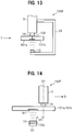
- FIG. 13 is a diagram showing a schematic configuration of an FSW apparatus according to a fourth example, and FIG. 14 shows the FSW apparatus of FIG. 13 in the direction of the arrow Y.
- an FSW apparatus 100F of the fourth example is such that the gradual cooling device 10 is provided on the opposite side of the to-be-welded members 101a and 101b from the FSW tool 1A. Further, the FSW apparatus 100F includes a letter C-shaped frame 33 (fixation member) substantially shaped like the letter C when seen in the welding line direction.
- the gradual cooling device 10 is disposed at a position away from and vertically below the welding line 102 along which the to-be-welded member 101a and the to-be-welded member 101b are brought into butt-contact. With such a configuration, the gradual cooling device 10 performs the gradual cooling (heating) from the side opposite from where the FSW tool 1A performs welding.
- FIG. 14 shows, in the FSW apparatus 100F, the rotation center O1 of the FSW tool 1A and the gradual cooling device 10 (the end portion 10b thereof closer to the FSW tool 1A) are away from each other by the length of a distance E1.
- the gradual cooling device 10 is provided on the opposite side of the to-be-welded members 101a and 101b from the FSW tool 1A.
- the distance E1 can be set to be short, which enables the gradual cooling (post-heating) to start promptly after the welding by the FSW tool 1A, shortening the time lag between the end of welding and the start of the gradual cooling (post-heating).
- FIG. 15 is a diagram showing a schematic configuration of an FSW apparatus according to a third embodiment according to the present invention.
- an FSW apparatus 100G of the third embodiment includes a tool movement driving device 7A (a first driver) that moves the FSW tool 1A in the welding direction D.
- the FSW apparatus 100G also includes a gradual cooler welding direction movement driving device 9A (a second driver) that moves the gradual cooling device 10 in the welding direction D.
- the FSW tool 1A and the gradual cooling device 10 are configured to move in the welding direction D independently of each other.
- a control device 5G has a tool driving controller 5f that controls the tool movement driving device 7A, and a gradual cooler driving controller 5g that controls the gradual cooler welding direction movement driving device 9A.
- the FSW apparatus 100G of the third embodiment includes the tool movement driving device 7A that drives the FSW tool 1A in the welding direction D and the gradual cooler welding direction movement driving device 9A that drives the gradual cooling device 10 in the welding direction D.
- This enables the FSW tool 1A and the gradual cooling device 10 to be driven independently of each other, which makes control of higher accuracy possible.
- the amount of heat to apply to the weld site S may be increased by making the movement speed V2 of the gradual cooling device 10 slower than the movement speed V1 of the FSW tool 1A. This makes it easier for the weld site S to be maintained at a temperature close to a welding temperature.
- FIG. 16 is a diagram showing a schematic block configuration of an FSW apparatus according to a fifth example.
- an FSW apparatus 100H of the fifth example is the FSW apparatus 100A of the first embodiment additionally including a temperature measurement device 14 that measures the temperature of the weld site S (welding temperature).
- the temperature measurement device 14 measures the temperature of a measurement target in a contactless manner, and may be configured using what is called thermography.
- the temperature measurement device 14 is fixed to the fixation member 30 on which the gradual cooling device 10 is fixed.
- the temperature measurement device 14 is located close to the gradual cooling device 10 and between the gradual cooling device 10 and the FSW tool 1A. With this temperature measurement device 14, the temperature of the weld site S or the temperature in the vicinity of the weld site S (an area about to be heated by the gradual cooling device 10) can be measured.
- a control device 5H (a friction stir welding control device) includes a target temperature storage 5h that stores target temperatures to be set for the weld site S (a target temperature at which a site having undergone welding is to be maintained), and a heat amount calculator 5i that calculates the amount of heat to be applied to the weld site S based on the target temperature.
- the target temperature storage 5h stores a database of target temperatures which are determined based on associations between the kinds and thicknesses of the to-be-welded members 101a and 101b, the movement speed (travelling speed) of the FSW tool 1A, and the distance between the protrusion 11 and the gradual cooling device 10 (i.e., the distance between the rotation center O1 of the FSW tool 1A and the end portion 10b of the gradual cooling device 10).
- a target temperature suitable for the friction stir welding of the to-be-welded members 101a and 101b is selected from the target temperature storage 5h.
- the target temperatures are determined by previous tests or the like.
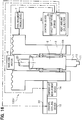
- FIG. 17 is an arithmetic block diagram of the FSW apparatus according to the fifth example.
- a target temperature is inputted to the heat amount calculator 5i, and the heat amount calculator 5i then controls the gradual cooling device 10 so that the target temperature inputted may be reached.
- the temperature of the weld site S (the welding temperature) measured by the temperature measurement device 14 is inputted to the heat amount calculator 5i.
- the heat amount calculator 5i compares the welding temperature with the target temperature, and controls the gradual cooling device 10 so that the amount of heat outputted from the gradual cooling device 10 may be such that the welding temperature has zero deviation from the target temperature. Feedback control is thus performed using the temperature measured by the temperature measurement device 14.
- FIG. 18 is a flowchart illustrating the operation of the FSW apparatus according to the fifth example.
- Step S10 the control device 5H determines whether the FSW apparatus 100H has started friction stir welding. It is determined that the FSW apparatus 100H has started friction stir welding when the welding tool 1 starts welding the to-be-welded members 101a and 101b along the welding line 102 after starting rotating until the temperature rises to a point where the welding tool 1 can perform welding.
- Step S10 when the control device 5H determines that the welding has not started (No), the processing of Step S10 is repeated, and when the control device 5H determines that the welding has started (Yes), the processing proceeds to Step S20.
- Step S20 the control device 5H starts gradual cooling (post-heating, post-heat application) by the gradual cooling device 10. Specifically, based on a target temperature, the control device 5H controls the amount of heat to be applied from the gradual cooling device 10 to the weld site S.
- Step S30 the control device 5H acquires a welding temperature T of the weld site S using the temperature measurement device 14.
- Step S40 the control device 5H calculates the amount of heat to be applied to the weld site S.
- the heat amount calculator 5i of the control device 5H compares the welding temperature T acquired in Step S30 with the target temperature determined, and controls the gradual cooling device 10 so that the welding temperature T may have zero deviation from (or may equal) the target temperature. Thereby, the weld site S is gradually cooled (heated). In other words, the weld site S is heated at a temperature which does not alter the metallographic structure that the weld site S has at the completion of welding.
- Step S50 the control device 5H determines whether the welding has finished. Whether the welding has finished is determined based on whether the FSW apparatus 100H has moved a preset distance. In Step S50, if the control device 5H determines that the welding has not finished (No), the processing is returned to Step S30, and if the control device 5H determines that the welding has finished (Yes), the processing proceeds to Step S60.
- Step S60 the control device 5H determines whether the FSW tool 1A has moved a predetermined distance ⁇ from the welding end point. Whether the FSW tool 1A has moved the predetermined distance ⁇ can be determined based for example on elapsed time calculated from the movement speed. In Step S60, if the control device 5H determines that the FSW tool 1A has not moved the predetermined distance ⁇ from the welding end point (No), the processing returns to Step S30, and if the control device 5H determines that the FSW tool 1A has moved the predetermined distance ⁇ (Yes), the processing proceeds to Step S70.
- Step S70 the control device 5H stops the power supply to the gradual cooling device 10 to end the gradual cooling.
- the fifth example includes the control device 5H connected to the FSW apparatus 100H which includes: the FSW tool 1A that welds a plurality of to-be-welded members 101a and 101b to each other by friction stir; the gradual cooling device 10 that gradually cools the weld site S of the to-be-welded members 101a and 101b welded by the FSW tool 1A; and the temperature measurement device 14 that measures the welding temperature T of the weld site S.
- the control device 5H includes the target temperature storage 5h that stores target temperatures to be set for the weld site S, and the heat amount calculator 5i that calculates the amount of heat to be applied to the weld site S based on the target temperature.
- the heat amount calculator 5i controls the gradual cooling device 10 so that the welding temperature T may have zero deviation from the target temperature.
- temperature management of the weld site S can be carried out with high accuracy, which may prevent metallographic alteration of the weld site S. As a result, friction stir welding with high accuracy can be achieved.
- FIG. 19 is a schematic diagram of an FSW apparatus according to the sixth example.
- an FSW apparatus 100I of the sixth example is such that the gradual cooling device 10 is tilted toward the FSW tool 1A with respect to the vertical direction.
- the gradual cooling device 10 is configured with, for example, a high-frequency heat source or an optical heat source using laser light.
- Such a configuration allows a gradual cooling start position (heating start position) P2 of the weld site S to be closer to the FSW tool 1A than the first example, and thus can shorten the time lag between the end of welding by the FSW tool 1A and the start of gradual cooling. This consequently can help prevent the weld site S from undergoing metallographic alteration, and achieve high-quality friction stir welding.
- the present invention is not limited to the embodiments described above, and further contains various modifications.
- the above embodiments have been described in detail to merely facilitate the understanding of the present invention, and the present invention does not necessarily have to include all the configurations described herein.
- part of a configuration in a certain embodiment may be replaced by a configuration in another embodiment, or a configuration in a certain embodiment may be added to a configuration in another embodiment.
- a configuration included in another embodiment may be added, deleted, or replaced.
- the gradual cooling device 10 is attached to the housing 3 via the fixation member 30 in the cases described in the above embodiments and examples but the gradual cooling device 10 may be fixed directly to the housing 3.
- the FSW apparatuses 100A to 100I are moved with the to-be-welded members 101a and 101b being stationary in the examples described in the above embodiments, but instead, the to-be-welded members 101a and 101b may be moved with the FSW apparatuses 100A to 100I being stationary.
Landscapes
- Engineering & Computer Science (AREA)
- Mechanical Engineering (AREA)
- Chemical & Material Sciences (AREA)
- Physics & Mathematics (AREA)
- Thermal Sciences (AREA)
- Crystallography & Structural Chemistry (AREA)
- Materials Engineering (AREA)
- Metallurgy (AREA)
- Organic Chemistry (AREA)
- Pressure Welding/Diffusion-Bonding (AREA)
- Heat Treatment Of Articles (AREA)
Claims (14)
- Appareil de soudage par agitation-friction comprenant :un outil de soudage par agitation-friction (1A) qui est maintenu par un corps principal d'appareil (3) et qui soude une pluralité d'éléments qu'il s'agit de souder les uns aux autres par agitation-friction ; etun dispositif de refroidissement progressif (10) qui refroidit progressivement un site de soudage (S) des éléments qu'il s'agit de souder ainsi soudés par l'outil de soudage par agitation-friction (1A),caractérisé en ce que :le corps principal d'appareil (3) inclut un moyen d'entraînement de déplacement en direction de soudage (9) du dispositif de refroidissement progressif qui déplace le dispositif de refroidissement progressif (10) dans une direction de soudage (D) ;dans lequel le moyen d'entraînement de déplacement en direction de soudage (9) du dispositif de refroidissement progressif déplace le dispositif de refroidissement progressif (10) pour changer une distance depuis le dispositif de refroidissement progressif (10) jusqu'à l'outil de soudage par agitation-friction (1A), de sorte que la position du dispositif de refroidissement progressif (10) peut être changée dans la direction de soudage (D) en accord avec la vitesse de déplacement de l'outil de soudage par agitation-friction (1A).
- Appareil de soudage par agitation-friction comprenant :un outil de soudage par agitation-friction (1A) qui est maintenu par un corps principal d'appareil (3) et qui soude une pluralité d'éléments qu'il s'agit de souder les uns aux autres par agitation-friction ;un dispositif de refroidissement progressif (10) qui refroidit progressivement un site de soudage (S) des éléments qu'il s'agit de souder ainsi soudés par l'outil de soudage par agitation-friction (1A) ;un premier moyen d'entraînement (7A) qui déplace l'outil de soudage par agitation-friction (1A) dans une direction de soudage (D) ;caractérisé par :un second moyen d'entraînement (9A) qui déplace le dispositif de refroidissement progressif (10) dans la direction de soudage ;dans lequel le second moyen d'entraînement (9A) déplace le dispositif de refroidissement progressif (10) dans la direction de soudage pour changer une distance depuis le dispositif de refroidissement progressif (10) jusqu'à l'outil de soudage par agitation-friction (1A), de sorte que l'outil de soudage par agitation-friction (1A) et le dispositif de refroidissement progressif (10) peuvent être entraînés indépendamment l'un de l'autre, ce qui rend possible une commande de haute précision.
- Appareil de soudage par agitation-friction selon la revendication 1 ou 2, dans lequel
le dispositif de refroidissement progressif (10) est une source de chaleur sans contact qui chauffe le site de soudage (S) sans venir en contact avec le site de soudage (S). - Appareil de soudage par agitation-friction selon la revendication 1 ou 2, comprenant en outre un dispositif d'entraînement de déplacement axial du dispositif de refroidissement progressif qui déplace le dispositif de refroidissement progressif (10) verticalement par rapport à l'outil de soudage par agitation-friction (1A).
- Appareil de soudage par agitation-friction selon la revendication 3, dans lequel
la source de chaleur sans contact est une source de chaleur à haute fréquence. - Appareil de soudage par agitation-friction selon la revendication 3,
dans lequel la source de chaleur sans contact est une source de chaleur optique. - Appareil de soudage par agitation-friction selon la revendication 1, comprenant :un moyen d'entraînement de déplacement d'outil (7) qui déplace l'outil de soudage par agitation-friction le long d'une ligne de soudage ; etun contrôleur de quantité de chaleur (5a) qui commande une quantité de chaleur à appliquer au site de soudage (S) par le dispositif de refroidissement progressif (10), dans lequelle contrôleur de quantité de chaleur (5a) augmente la quantité de chaleur à appliquer au site de soudage (S) quand l'outil de soudage par agitation-friction (1A) est déplacé en éloignement du site de soudage (S) à la fin du soudage.
- Appareil de soudage par agitation-friction selon la revendication 1, comprenant :un moyen d'entraînement de déplacement d'outil (7) qui déplace l'outil de soudage par agitation-friction le long d'une ligne de soudage ;un moyen d'entraînement de déplacement en direction axiale (8) du dispositif de refroidissement progressif qui déplace le dispositif de refroidissement progressif (10) en rapprochement et en éloignement du site de soudage (S) ; etun contrôleur d'entraînement du dispositif de refroidissement progressif (5b) qui commande le moyen d'entraînement de déplacement en direction axiale (8) du dispositif de refroidissement progressif, dans lequelle contrôleur d'entraînement du dispositif de refroidissement progressif (5b) commande le moyen d'entraînement de déplacement en direction axiale (8) du dispositif de refroidissement progressif pour entraîner le dispositif de refroidissement progressif (10) en direction du site de soudage (S) quand l'outil de soudage par agitation-friction (1A) est déplacé en éloignement du site de soudage (S) à la fin du soudage.
- Appareil de soudage par agitation-friction selon la revendication 1 ou 2, dans lequel
le corps principal d'appareil (3) inclut une pluralité de dispositifs de refroidissement progressif (10) agencés dans la direction de soudage. - Appareil de soudage par agitation-friction selon la revendication 1 ou 2, dans lequel
le dispositif de refroidissement progressif (10) est prévu sur un côté opposé des éléments qu'il s'agit de souder par rapport à l'outil de soudage par agitation-friction (1A). - Appareil de soudage par agitation-friction selon la revendication 1 ou 2, dans lequel
le dispositif de refroidissement progressif (10) est disposé avec une inclinaison en direction de l'outil de soudage par agitation-friction (1A). - Appareil de soudage par agitation-friction selon la revendication 1 ou 2, comprenant un dispositif de mesure de température sans contact qui détecte une température du site de soudage (S).
- Procédé de soudage par agitation-friction caractérisé en ce qu'il comprend :par un outil de soudage par agitation-friction (1A) qui est tenu par un corps principal d'appareil (3) et qui soude une pluralité d'éléments qu'il s'agit de souder les uns aux autres par agitation-friction, l'étape consistant à souder les uns aux autres les éléments qu'il s'agit de souder ;et étant caractérisé par :
après le soudage, par un dispositif de refroidissement progressif (10) prévu pour être déplaçable dans une direction de soudage par rapport au corps principal d'appareil (3), l'étape consistant à refroidir progressivement un site de soudage (S) des éléments qu'il s'agit de souder ainsi soudés par l'outil de soudage par agitation-friction (1A). - Procédé de soudage par agitation-friction selon la revendication 13, comprenant l'étape consistant à :mesurer une température de soudage du site de soudage ;calculer une déviation de la température de soudage depuis une température cible fixée pour le site de soudage (S) ; etexécuter le refroidissement progressif de telle façon que la déviation devient égale à zéro.
Applications Claiming Priority (1)
| Application Number | Priority Date | Filing Date | Title |
|---|---|---|---|
| JP2017066641A JP6231236B1 (ja) | 2017-03-30 | 2017-03-30 | 摩擦攪拌接合装置及び摩擦攪拌接合制御装置並びに摩擦攪拌接合方法 |
Publications (2)
| Publication Number | Publication Date |
|---|---|
| EP3398708A1 EP3398708A1 (fr) | 2018-11-07 |
| EP3398708B1 true EP3398708B1 (fr) | 2021-02-17 |
Family
ID=60321183
Family Applications (1)
| Application Number | Title | Priority Date | Filing Date |
|---|---|---|---|
| EP18165079.7A Not-in-force EP3398708B1 (fr) | 2017-03-30 | 2018-03-29 | Appareil de soudage par friction-malaxage, dispositif de commande de soudage par friction-malaxage et procédé de soudage par friction-malaxage |
Country Status (5)
| Country | Link |
|---|---|
| US (1) | US10596657B2 (fr) |
| EP (1) | EP3398708B1 (fr) |
| JP (1) | JP6231236B1 (fr) |
| KR (1) | KR102182975B1 (fr) |
| CN (1) | CN108687439B (fr) |
Families Citing this family (8)
| Publication number | Priority date | Publication date | Assignee | Title |
|---|---|---|---|---|
| CN108890118B (zh) * | 2018-08-28 | 2020-08-28 | 中国船舶重工集团公司第七二五研究所 | 一种钛及钛合金搅拌摩擦焊用背部辅助加热装置 |
| US11331745B2 (en) * | 2019-02-01 | 2022-05-17 | Kabushiki Kaisha Toshiba | Distance measuring device, friction stir welding apparatus, and friction stir welding method |
| US10442029B1 (en) * | 2019-04-10 | 2019-10-15 | King Saud University | Method of friction stir spot welding |
| JP7619025B2 (ja) * | 2020-12-03 | 2025-01-22 | 日本軽金属株式会社 | 接合装置及び接合方法 |
| CN113967783B (zh) * | 2021-10-22 | 2022-08-02 | 南京工业大学 | 一种同轴喷雾冷却耦合辅助fsw的装置及使用方法 |
| CN115026406B (zh) * | 2022-05-31 | 2023-02-14 | 大连理工大学 | 基于红外热像仪的搅拌摩擦焊核心区温度在位表征方法 |
| CN117340414A (zh) * | 2023-03-22 | 2024-01-05 | 澳门发展及质量研究所 | 一种固相成型加工方法 |
| CN119536422A (zh) * | 2024-11-19 | 2025-02-28 | 中国联合网络通信集团有限公司 | 一种温度控制方法、装置、电子设备及存储介质 |
Family Cites Families (10)
| Publication number | Priority date | Publication date | Assignee | Title |
|---|---|---|---|---|
| JP4235874B2 (ja) * | 2001-09-20 | 2009-03-11 | 株式会社安川電機 | 摩擦撹拌接合法の加熱装置 |
| JP4468125B2 (ja) | 2004-09-27 | 2010-05-26 | 三菱重工業株式会社 | 摩擦撹拌接合方法及び装置 |
| KR101397386B1 (ko) * | 2005-12-13 | 2014-05-26 | 엑스테라 메디컬 코퍼레이션 | 혈액으로부터 병원성 미생물, 염증 세포 또는 염증단백질의 체외 제거를 위한 방법 |
| JP5243083B2 (ja) | 2008-04-01 | 2013-07-24 | 株式会社豊田自動織機 | 摩擦圧接方法 |
| US9113203B2 (en) * | 2012-06-28 | 2015-08-18 | Google Inc. | Generating a sequence of audio fingerprints at a set top box |
| US9033205B2 (en) * | 2012-07-27 | 2015-05-19 | Alfredo CASTILLO | Friction stir welding with temperature control |
| WO2015045421A1 (fr) * | 2013-09-30 | 2015-04-02 | Jfeスチール株式会社 | Procédé d'assemblage par friction/brassage de tôles et procédé de production d'un joint lié |
| WO2015045299A1 (fr) * | 2013-09-30 | 2015-04-02 | Jfeスチール株式会社 | Procédé de soudage par friction-malaxage pour acier de structure et procédé de fabrication de raccord lié pour acier de structure |
| JP6004147B1 (ja) * | 2015-03-19 | 2016-10-05 | Jfeスチール株式会社 | 構造用鋼の摩擦撹拌接合装置 |
| JP5883978B1 (ja) | 2015-08-06 | 2016-03-15 | 株式会社日立パワーソリューションズ | 摩擦攪拌接合装置および摩擦攪拌接合制御方法 |
-
2017
- 2017-03-30 JP JP2017066641A patent/JP6231236B1/ja active Active
-
2018
- 2018-03-27 KR KR1020180035167A patent/KR102182975B1/ko active Active
- 2018-03-27 CN CN201810258847.8A patent/CN108687439B/zh not_active Expired - Fee Related
- 2018-03-29 US US15/939,970 patent/US10596657B2/en active Active
- 2018-03-29 EP EP18165079.7A patent/EP3398708B1/fr not_active Not-in-force
Non-Patent Citations (1)
| Title |
|---|
| None * |
Also Published As
| Publication number | Publication date |
|---|---|
| JP6231236B1 (ja) | 2017-11-15 |
| JP2018167292A (ja) | 2018-11-01 |
| US20180281104A1 (en) | 2018-10-04 |
| KR102182975B1 (ko) | 2020-11-25 |
| CN108687439B (zh) | 2021-08-20 |
| KR20180111589A (ko) | 2018-10-11 |
| US10596657B2 (en) | 2020-03-24 |
| CN108687439A (zh) | 2018-10-23 |
| EP3398708A1 (fr) | 2018-11-07 |
Similar Documents
| Publication | Publication Date | Title |
|---|---|---|
| EP3398708B1 (fr) | Appareil de soudage par friction-malaxage, dispositif de commande de soudage par friction-malaxage et procédé de soudage par friction-malaxage | |
| EP3332903B1 (fr) | Dispositif de soudage par friction-malaxage et procédé de commande de soudage par friction-malaxage | |
| EP1844890A1 (fr) | Procédé et dispositif d'assemblage par friction agitation pour assembler un élément métallique revétu avec un autre élément métallique avec préchauffage du revètement avant soudure par friction agitation | |
| US7156277B2 (en) | Friction stir welding method and apparatus | |
| JP4235874B2 (ja) | 摩擦撹拌接合法の加熱装置 | |
| US20180257169A1 (en) | Friction stir spot welding device and friction stir spot welding method | |
| JP7126719B2 (ja) | 金属材の固相接合方法及び固相接合装置 | |
| KR20110056473A (ko) | 섬유 레이저 포함 레이저 용접툴 | |
| JP2006021217A (ja) | スポット接合用摩擦撹拌接合装置 | |
| JP2004154790A (ja) | 摩擦攪拌接合装置とその接合方法 | |
| WO2016080101A1 (fr) | Procédé de liaison et appareil de liaison | |
| US5165589A (en) | Concurrent friction/joule heating weld process | |
| KR102926375B1 (ko) | 표시장치, 및 성형장치 | |
| JP2021504141A (ja) | 摩擦撹拌溶接システムにおいて溶接ショルダの溶接方向を実質的に遅延なく変更する装置及び方法 | |
| JP2022135403A (ja) | レーザ溶接方法及び溶接装置 | |
| JP2002103102A (ja) | 加工装置および加工方法 | |
| JP4235873B2 (ja) | 摩擦撹拌接合法の加熱装置 | |
| JP2023147697A (ja) | 摩擦攪拌接合装置及び摩擦攪拌接合方法 | |
| JP2014161858A (ja) | 硬化肉盛溶接装置及び方法 | |
| US20240408689A1 (en) | Additive manufacturing method, additive manufacturing system, and non-transitory computer-readable recording medium | |
| CN114192985B (zh) | 磁场辅助激光抛光装置与磁场辅助抛光方法 | |
| JP2025076236A (ja) | 摩擦撹拌用回転部材、ロボット型接合装置、及び接合部品 | |
| JP7817801B2 (ja) | レーザ焼入れ装置 | |
| JP2020049532A (ja) | 摩擦攪拌接合装置及び摩擦攪拌接合方法 | |
| CN111936258A (zh) | 用于焊接工艺,特别是电弧增材制造工艺的均匀冷却装置 |
Legal Events
| Date | Code | Title | Description |
|---|---|---|---|
| PUAI | Public reference made under article 153(3) epc to a published international application that has entered the european phase |
Free format text: ORIGINAL CODE: 0009012 |
|
| STAA | Information on the status of an ep patent application or granted ep patent |
Free format text: STATUS: REQUEST FOR EXAMINATION WAS MADE |
|
| 17P | Request for examination filed |
Effective date: 20180604 |
|
| AK | Designated contracting states |
Kind code of ref document: A1 Designated state(s): AL AT BE BG CH CY CZ DE DK EE ES FI FR GB GR HR HU IE IS IT LI LT LU LV MC MK MT NL NO PL PT RO RS SE SI SK SM TR |
|
| AX | Request for extension of the european patent |
Extension state: BA ME |
|
| RAP1 | Party data changed (applicant data changed or rights of an application transferred) |
Owner name: HITACHI POWER SOLUTIONS CO., LTD. |
|
| STAA | Information on the status of an ep patent application or granted ep patent |
Free format text: STATUS: EXAMINATION IS IN PROGRESS |
|
| 17Q | First examination report despatched |
Effective date: 20191119 |
|
| RIC1 | Information provided on ipc code assigned before grant |
Ipc: C21D 9/50 20060101ALI20200722BHEP Ipc: B23K 20/12 20060101AFI20200722BHEP Ipc: B23K 101/18 20060101ALN20200722BHEP |
|
| RIC1 | Information provided on ipc code assigned before grant |
Ipc: B23K 101/18 20060101ALN20200820BHEP Ipc: B23K 20/12 20060101AFI20200820BHEP Ipc: C21D 9/50 20060101ALI20200820BHEP |
|
| GRAP | Despatch of communication of intention to grant a patent |
Free format text: ORIGINAL CODE: EPIDOSNIGR1 |
|
| STAA | Information on the status of an ep patent application or granted ep patent |
Free format text: STATUS: GRANT OF PATENT IS INTENDED |
|
| RIC1 | Information provided on ipc code assigned before grant |
Ipc: B23K 20/12 20060101AFI20200910BHEP Ipc: B23K 101/18 20060101ALN20200910BHEP Ipc: C21D 9/50 20060101ALI20200910BHEP |
|
| INTG | Intention to grant announced |
Effective date: 20200930 |
|
| GRAS | Grant fee paid |
Free format text: ORIGINAL CODE: EPIDOSNIGR3 |
|
| GRAA | (expected) grant |
Free format text: ORIGINAL CODE: 0009210 |
|
| STAA | Information on the status of an ep patent application or granted ep patent |
Free format text: STATUS: THE PATENT HAS BEEN GRANTED |
|
| AK | Designated contracting states |
Kind code of ref document: B1 Designated state(s): AL AT BE BG CH CY CZ DE DK EE ES FI FR GB GR HR HU IE IS IT LI LT LU LV MC MK MT NL NO PL PT RO RS SE SI SK SM TR |
|
| REG | Reference to a national code |
Ref country code: GB Ref legal event code: FG4D |
|
| REG | Reference to a national code |
Ref country code: CH Ref legal event code: EP |
|
| REG | Reference to a national code |
Ref country code: DE Ref legal event code: R096 Ref document number: 602018012498 Country of ref document: DE |
|
| REG | Reference to a national code |
Ref country code: AT Ref legal event code: REF Ref document number: 1360853 Country of ref document: AT Kind code of ref document: T Effective date: 20210315 |
|
| REG | Reference to a national code |
Ref country code: SE Ref legal event code: TRGR |
|
| REG | Reference to a national code |
Ref country code: IE Ref legal event code: FG4D |
|
| REG | Reference to a national code |
Ref country code: LT Ref legal event code: MG9D |
|
| REG | Reference to a national code |
Ref country code: NL Ref legal event code: MP Effective date: 20210217 |
|
| PG25 | Lapsed in a contracting state [announced via postgrant information from national office to epo] |
Ref country code: PT Free format text: LAPSE BECAUSE OF FAILURE TO SUBMIT A TRANSLATION OF THE DESCRIPTION OR TO PAY THE FEE WITHIN THE PRESCRIBED TIME-LIMIT Effective date: 20210617 Ref country code: NO Free format text: LAPSE BECAUSE OF FAILURE TO SUBMIT A TRANSLATION OF THE DESCRIPTION OR TO PAY THE FEE WITHIN THE PRESCRIBED TIME-LIMIT Effective date: 20210517 Ref country code: LT Free format text: LAPSE BECAUSE OF FAILURE TO SUBMIT A TRANSLATION OF THE DESCRIPTION OR TO PAY THE FEE WITHIN THE PRESCRIBED TIME-LIMIT Effective date: 20210217 Ref country code: BG Free format text: LAPSE BECAUSE OF FAILURE TO SUBMIT A TRANSLATION OF THE DESCRIPTION OR TO PAY THE FEE WITHIN THE PRESCRIBED TIME-LIMIT Effective date: 20210517 Ref country code: GR Free format text: LAPSE BECAUSE OF FAILURE TO SUBMIT A TRANSLATION OF THE DESCRIPTION OR TO PAY THE FEE WITHIN THE PRESCRIBED TIME-LIMIT Effective date: 20210518 Ref country code: HR Free format text: LAPSE BECAUSE OF FAILURE TO SUBMIT A TRANSLATION OF THE DESCRIPTION OR TO PAY THE FEE WITHIN THE PRESCRIBED TIME-LIMIT Effective date: 20210217 Ref country code: FI Free format text: LAPSE BECAUSE OF FAILURE TO SUBMIT A TRANSLATION OF THE DESCRIPTION OR TO PAY THE FEE WITHIN THE PRESCRIBED TIME-LIMIT Effective date: 20210217 |
|
| REG | Reference to a national code |
Ref country code: AT Ref legal event code: MK05 Ref document number: 1360853 Country of ref document: AT Kind code of ref document: T Effective date: 20210217 |
|
| PG25 | Lapsed in a contracting state [announced via postgrant information from national office to epo] |
Ref country code: LV Free format text: LAPSE BECAUSE OF FAILURE TO SUBMIT A TRANSLATION OF THE DESCRIPTION OR TO PAY THE FEE WITHIN THE PRESCRIBED TIME-LIMIT Effective date: 20210217 Ref country code: PL Free format text: LAPSE BECAUSE OF FAILURE TO SUBMIT A TRANSLATION OF THE DESCRIPTION OR TO PAY THE FEE WITHIN THE PRESCRIBED TIME-LIMIT Effective date: 20210217 Ref country code: NL Free format text: LAPSE BECAUSE OF FAILURE TO SUBMIT A TRANSLATION OF THE DESCRIPTION OR TO PAY THE FEE WITHIN THE PRESCRIBED TIME-LIMIT Effective date: 20210217 Ref country code: RS Free format text: LAPSE BECAUSE OF FAILURE TO SUBMIT A TRANSLATION OF THE DESCRIPTION OR TO PAY THE FEE WITHIN THE PRESCRIBED TIME-LIMIT Effective date: 20210217 |
|
| PG25 | Lapsed in a contracting state [announced via postgrant information from national office to epo] |
Ref country code: IS Free format text: LAPSE BECAUSE OF FAILURE TO SUBMIT A TRANSLATION OF THE DESCRIPTION OR TO PAY THE FEE WITHIN THE PRESCRIBED TIME-LIMIT Effective date: 20210617 |
|
| PG25 | Lapsed in a contracting state [announced via postgrant information from national office to epo] |
Ref country code: AT Free format text: LAPSE BECAUSE OF FAILURE TO SUBMIT A TRANSLATION OF THE DESCRIPTION OR TO PAY THE FEE WITHIN THE PRESCRIBED TIME-LIMIT Effective date: 20210217 Ref country code: SM Free format text: LAPSE BECAUSE OF FAILURE TO SUBMIT A TRANSLATION OF THE DESCRIPTION OR TO PAY THE FEE WITHIN THE PRESCRIBED TIME-LIMIT Effective date: 20210217 Ref country code: EE Free format text: LAPSE BECAUSE OF FAILURE TO SUBMIT A TRANSLATION OF THE DESCRIPTION OR TO PAY THE FEE WITHIN THE PRESCRIBED TIME-LIMIT Effective date: 20210217 Ref country code: CZ Free format text: LAPSE BECAUSE OF FAILURE TO SUBMIT A TRANSLATION OF THE DESCRIPTION OR TO PAY THE FEE WITHIN THE PRESCRIBED TIME-LIMIT Effective date: 20210217 |
|
| REG | Reference to a national code |
Ref country code: CH Ref legal event code: PL |
|
| REG | Reference to a national code |
Ref country code: DE Ref legal event code: R097 Ref document number: 602018012498 Country of ref document: DE |
|
| PG25 | Lapsed in a contracting state [announced via postgrant information from national office to epo] |
Ref country code: MC Free format text: LAPSE BECAUSE OF FAILURE TO SUBMIT A TRANSLATION OF THE DESCRIPTION OR TO PAY THE FEE WITHIN THE PRESCRIBED TIME-LIMIT Effective date: 20210217 Ref country code: RO Free format text: LAPSE BECAUSE OF FAILURE TO SUBMIT A TRANSLATION OF THE DESCRIPTION OR TO PAY THE FEE WITHIN THE PRESCRIBED TIME-LIMIT Effective date: 20210217 Ref country code: SK Free format text: LAPSE BECAUSE OF FAILURE TO SUBMIT A TRANSLATION OF THE DESCRIPTION OR TO PAY THE FEE WITHIN THE PRESCRIBED TIME-LIMIT Effective date: 20210217 Ref country code: DK Free format text: LAPSE BECAUSE OF FAILURE TO SUBMIT A TRANSLATION OF THE DESCRIPTION OR TO PAY THE FEE WITHIN THE PRESCRIBED TIME-LIMIT Effective date: 20210217 |
|
| REG | Reference to a national code |
Ref country code: BE Ref legal event code: MM Effective date: 20210331 |
|
| PLBE | No opposition filed within time limit |
Free format text: ORIGINAL CODE: 0009261 |
|
| STAA | Information on the status of an ep patent application or granted ep patent |
Free format text: STATUS: NO OPPOSITION FILED WITHIN TIME LIMIT |
|
| 26N | No opposition filed |
Effective date: 20211118 |
|
| PG25 | Lapsed in a contracting state [announced via postgrant information from national office to epo] |
Ref country code: ES Free format text: LAPSE BECAUSE OF FAILURE TO SUBMIT A TRANSLATION OF THE DESCRIPTION OR TO PAY THE FEE WITHIN THE PRESCRIBED TIME-LIMIT Effective date: 20210217 Ref country code: AL Free format text: LAPSE BECAUSE OF FAILURE TO SUBMIT A TRANSLATION OF THE DESCRIPTION OR TO PAY THE FEE WITHIN THE PRESCRIBED TIME-LIMIT Effective date: 20210217 Ref country code: CH Free format text: LAPSE BECAUSE OF NON-PAYMENT OF DUE FEES Effective date: 20210331 Ref country code: IE Free format text: LAPSE BECAUSE OF NON-PAYMENT OF DUE FEES Effective date: 20210329 Ref country code: LI Free format text: LAPSE BECAUSE OF NON-PAYMENT OF DUE FEES Effective date: 20210331 Ref country code: LU Free format text: LAPSE BECAUSE OF NON-PAYMENT OF DUE FEES Effective date: 20210329 |
|
| PG25 | Lapsed in a contracting state [announced via postgrant information from national office to epo] |
Ref country code: SI Free format text: LAPSE BECAUSE OF FAILURE TO SUBMIT A TRANSLATION OF THE DESCRIPTION OR TO PAY THE FEE WITHIN THE PRESCRIBED TIME-LIMIT Effective date: 20210217 |
|
| PG25 | Lapsed in a contracting state [announced via postgrant information from national office to epo] |
Ref country code: IS Free format text: LAPSE BECAUSE OF FAILURE TO SUBMIT A TRANSLATION OF THE DESCRIPTION OR TO PAY THE FEE WITHIN THE PRESCRIBED TIME-LIMIT Effective date: 20210617 |
|
| PG25 | Lapsed in a contracting state [announced via postgrant information from national office to epo] |
Ref country code: BE Free format text: LAPSE BECAUSE OF NON-PAYMENT OF DUE FEES Effective date: 20210331 |
|
| PG25 | Lapsed in a contracting state [announced via postgrant information from national office to epo] |
Ref country code: CY Free format text: LAPSE BECAUSE OF FAILURE TO SUBMIT A TRANSLATION OF THE DESCRIPTION OR TO PAY THE FEE WITHIN THE PRESCRIBED TIME-LIMIT Effective date: 20210217 |
|
| PG25 | Lapsed in a contracting state [announced via postgrant information from national office to epo] |
Ref country code: HU Free format text: LAPSE BECAUSE OF FAILURE TO SUBMIT A TRANSLATION OF THE DESCRIPTION OR TO PAY THE FEE WITHIN THE PRESCRIBED TIME-LIMIT; INVALID AB INITIO Effective date: 20180329 |
|
| PG25 | Lapsed in a contracting state [announced via postgrant information from national office to epo] |
Ref country code: MK Free format text: LAPSE BECAUSE OF FAILURE TO SUBMIT A TRANSLATION OF THE DESCRIPTION OR TO PAY THE FEE WITHIN THE PRESCRIBED TIME-LIMIT Effective date: 20210217 |
|
| PGFP | Annual fee paid to national office [announced via postgrant information from national office to epo] |
Ref country code: DE Payment date: 20240130 Year of fee payment: 7 Ref country code: GB Payment date: 20240208 Year of fee payment: 7 |
|
| PGFP | Annual fee paid to national office [announced via postgrant information from national office to epo] |
Ref country code: SE Payment date: 20240212 Year of fee payment: 7 Ref country code: IT Payment date: 20240212 Year of fee payment: 7 Ref country code: FR Payment date: 20240213 Year of fee payment: 7 |
|
| PG25 | Lapsed in a contracting state [announced via postgrant information from national office to epo] |
Ref country code: MT Free format text: LAPSE BECAUSE OF FAILURE TO SUBMIT A TRANSLATION OF THE DESCRIPTION OR TO PAY THE FEE WITHIN THE PRESCRIBED TIME-LIMIT Effective date: 20210217 |
|
| REG | Reference to a national code |
Ref country code: DE Ref legal event code: R119 Ref document number: 602018012498 Country of ref document: DE |
|
| REG | Reference to a national code |
Ref country code: SE Ref legal event code: EUG |
|
| GBPC | Gb: european patent ceased through non-payment of renewal fee |
Effective date: 20250329 |
|
| PG25 | Lapsed in a contracting state [announced via postgrant information from national office to epo] |
Ref country code: TR Free format text: LAPSE BECAUSE OF FAILURE TO SUBMIT A TRANSLATION OF THE DESCRIPTION OR TO PAY THE FEE WITHIN THE PRESCRIBED TIME-LIMIT Effective date: 20210217 |
|
| PG25 | Lapsed in a contracting state [announced via postgrant information from national office to epo] |
Ref country code: DE Free format text: LAPSE BECAUSE OF NON-PAYMENT OF DUE FEES Effective date: 20251001 |
|
| PG25 | Lapsed in a contracting state [announced via postgrant information from national office to epo] |
Ref country code: GB Free format text: LAPSE BECAUSE OF NON-PAYMENT OF DUE FEES Effective date: 20250329 |
|
| PG25 | Lapsed in a contracting state [announced via postgrant information from national office to epo] |
Ref country code: FR Free format text: LAPSE BECAUSE OF NON-PAYMENT OF DUE FEES Effective date: 20250331 Ref country code: IT Free format text: LAPSE BECAUSE OF NON-PAYMENT OF DUE FEES Effective date: 20250329 |
|
| PG25 | Lapsed in a contracting state [announced via postgrant information from national office to epo] |
Ref country code: SE Free format text: LAPSE BECAUSE OF NON-PAYMENT OF DUE FEES Effective date: 20250330 |