EP3399190A1 - Machine de travail - Google Patents
Machine de travail Download PDFInfo
- Publication number
- EP3399190A1 EP3399190A1 EP16881473.9A EP16881473A EP3399190A1 EP 3399190 A1 EP3399190 A1 EP 3399190A1 EP 16881473 A EP16881473 A EP 16881473A EP 3399190 A1 EP3399190 A1 EP 3399190A1
- Authority
- EP
- European Patent Office
- Prior art keywords
- hydraulic
- hydraulic pumps
- volumetric
- actuator
- flow rate
- Prior art date
- Legal status (The legal status is an assumption and is not a legal conclusion. Google has not performed a legal analysis and makes no representation as to the accuracy of the status listed.)
- Granted
Links
Images



Classifications
-
- E—FIXED CONSTRUCTIONS
- E02—HYDRAULIC ENGINEERING; FOUNDATIONS; SOIL SHIFTING
- E02F—DREDGING; SOIL-SHIFTING
- E02F9/00—Component parts of dredgers or soil-shifting machines, not restricted to one of the kinds covered by groups E02F3/00 - E02F7/00
- E02F9/20—Drives; Control devices
- E02F9/22—Hydraulic or pneumatic drives
- E02F9/2221—Control of flow rate; Load sensing arrangements
- E02F9/2232—Control of flow rate; Load sensing arrangements using one or more variable displacement pumps
- E02F9/2235—Control of flow rate; Load sensing arrangements using one or more variable displacement pumps including an electronic controller
-
- E—FIXED CONSTRUCTIONS
- E02—HYDRAULIC ENGINEERING; FOUNDATIONS; SOIL SHIFTING
- E02F—DREDGING; SOIL-SHIFTING
- E02F9/00—Component parts of dredgers or soil-shifting machines, not restricted to one of the kinds covered by groups E02F3/00 - E02F7/00
- E02F9/20—Drives; Control devices
- E02F9/22—Hydraulic or pneumatic drives
- E02F9/226—Safety arrangements, e.g. hydraulic driven fans, preventing cavitation, leakage, overheating
-
- E—FIXED CONSTRUCTIONS
- E02—HYDRAULIC ENGINEERING; FOUNDATIONS; SOIL SHIFTING
- E02F—DREDGING; SOIL-SHIFTING
- E02F9/00—Component parts of dredgers or soil-shifting machines, not restricted to one of the kinds covered by groups E02F3/00 - E02F7/00
- E02F9/20—Drives; Control devices
- E02F9/22—Hydraulic or pneumatic drives
- E02F9/2278—Hydraulic circuits
- E02F9/2289—Closed circuit
-
- E—FIXED CONSTRUCTIONS
- E02—HYDRAULIC ENGINEERING; FOUNDATIONS; SOIL SHIFTING
- E02F—DREDGING; SOIL-SHIFTING
- E02F9/00—Component parts of dredgers or soil-shifting machines, not restricted to one of the kinds covered by groups E02F3/00 - E02F7/00
- E02F9/20—Drives; Control devices
- E02F9/22—Hydraulic or pneumatic drives
- E02F9/2278—Hydraulic circuits
- E02F9/2292—Systems with two or more pumps
-
- E—FIXED CONSTRUCTIONS
- E02—HYDRAULIC ENGINEERING; FOUNDATIONS; SOIL SHIFTING
- E02F—DREDGING; SOIL-SHIFTING
- E02F9/00—Component parts of dredgers or soil-shifting machines, not restricted to one of the kinds covered by groups E02F3/00 - E02F7/00
- E02F9/20—Drives; Control devices
- E02F9/22—Hydraulic or pneumatic drives
- E02F9/2278—Hydraulic circuits
- E02F9/2296—Systems with a variable displacement pump
-
- E—FIXED CONSTRUCTIONS
- E02—HYDRAULIC ENGINEERING; FOUNDATIONS; SOIL SHIFTING
- E02F—DREDGING; SOIL-SHIFTING
- E02F9/00—Component parts of dredgers or soil-shifting machines, not restricted to one of the kinds covered by groups E02F3/00 - E02F7/00
- E02F9/26—Indicating devices
- E02F9/267—Diagnosing or detecting failure of vehicles
-
- E—FIXED CONSTRUCTIONS
- E02—HYDRAULIC ENGINEERING; FOUNDATIONS; SOIL SHIFTING
- E02F—DREDGING; SOIL-SHIFTING
- E02F9/00—Component parts of dredgers or soil-shifting machines, not restricted to one of the kinds covered by groups E02F3/00 - E02F7/00
- E02F9/26—Indicating devices
- E02F9/267—Diagnosing or detecting failure of vehicles
- E02F9/268—Diagnosing or detecting failure of vehicles with failure correction follow-up actions
-
- F—MECHANICAL ENGINEERING; LIGHTING; HEATING; WEAPONS; BLASTING
- F04—POSITIVE - DISPLACEMENT MACHINES FOR LIQUIDS; PUMPS FOR LIQUIDS OR ELASTIC FLUIDS
- F04B—POSITIVE-DISPLACEMENT MACHINES FOR LIQUIDS; PUMPS
- F04B49/00—Control, e.g. of pump delivery, or pump pressure of, or safety measures for, machines, pumps, or pumping installations, not otherwise provided for, or of interest apart from, groups F04B1/00 - F04B47/00
- F04B49/06—Control using electricity
-
- F—MECHANICAL ENGINEERING; LIGHTING; HEATING; WEAPONS; BLASTING
- F04—POSITIVE - DISPLACEMENT MACHINES FOR LIQUIDS; PUMPS FOR LIQUIDS OR ELASTIC FLUIDS
- F04B—POSITIVE-DISPLACEMENT MACHINES FOR LIQUIDS; PUMPS
- F04B49/00—Control, e.g. of pump delivery, or pump pressure of, or safety measures for, machines, pumps, or pumping installations, not otherwise provided for, or of interest apart from, groups F04B1/00 - F04B47/00
- F04B49/08—Regulating by delivery pressure
-
- F—MECHANICAL ENGINEERING; LIGHTING; HEATING; WEAPONS; BLASTING
- F04—POSITIVE - DISPLACEMENT MACHINES FOR LIQUIDS; PUMPS FOR LIQUIDS OR ELASTIC FLUIDS
- F04B—POSITIVE-DISPLACEMENT MACHINES FOR LIQUIDS; PUMPS
- F04B49/00—Control, e.g. of pump delivery, or pump pressure of, or safety measures for, machines, pumps, or pumping installations, not otherwise provided for, or of interest apart from, groups F04B1/00 - F04B47/00
- F04B49/10—Other safety measures
-
- F—MECHANICAL ENGINEERING; LIGHTING; HEATING; WEAPONS; BLASTING
- F04—POSITIVE - DISPLACEMENT MACHINES FOR LIQUIDS; PUMPS FOR LIQUIDS OR ELASTIC FLUIDS
- F04B—POSITIVE-DISPLACEMENT MACHINES FOR LIQUIDS; PUMPS
- F04B49/00—Control, e.g. of pump delivery, or pump pressure of, or safety measures for, machines, pumps, or pumping installations, not otherwise provided for, or of interest apart from, groups F04B1/00 - F04B47/00
- F04B49/10—Other safety measures
- F04B49/103—Responsive to speed
-
- F—MECHANICAL ENGINEERING; LIGHTING; HEATING; WEAPONS; BLASTING
- F04—POSITIVE - DISPLACEMENT MACHINES FOR LIQUIDS; PUMPS FOR LIQUIDS OR ELASTIC FLUIDS
- F04B—POSITIVE-DISPLACEMENT MACHINES FOR LIQUIDS; PUMPS
- F04B51/00—Testing machines, pumps, or pumping installations
-
- G—PHYSICS
- G01—MEASURING; TESTING
- G01M—TESTING STATIC OR DYNAMIC BALANCE OF MACHINES OR STRUCTURES; TESTING OF STRUCTURES OR APPARATUS, NOT OTHERWISE PROVIDED FOR
- G01M3/00—Investigating fluid-tightness of structures
- G01M3/02—Investigating fluid-tightness of structures by using fluid or vacuum
- G01M3/26—Investigating fluid-tightness of structures by using fluid or vacuum by measuring rate of loss or gain of fluid, e.g. by pressure-responsive devices, by flow detectors
- G01M3/28—Investigating fluid-tightness of structures by using fluid or vacuum by measuring rate of loss or gain of fluid, e.g. by pressure-responsive devices, by flow detectors for pipes, cables or tubes; for pipe joints or seals; for valves ; for welds
- G01M3/2853—Investigating fluid-tightness of structures by using fluid or vacuum by measuring rate of loss or gain of fluid, e.g. by pressure-responsive devices, by flow detectors for pipes, cables or tubes; for pipe joints or seals; for valves ; for welds for pipe joints or seals
-
- G—PHYSICS
- G01—MEASURING; TESTING
- G01M—TESTING STATIC OR DYNAMIC BALANCE OF MACHINES OR STRUCTURES; TESTING OF STRUCTURES OR APPARATUS, NOT OTHERWISE PROVIDED FOR
- G01M3/00—Investigating fluid-tightness of structures
- G01M3/02—Investigating fluid-tightness of structures by using fluid or vacuum
- G01M3/26—Investigating fluid-tightness of structures by using fluid or vacuum by measuring rate of loss or gain of fluid, e.g. by pressure-responsive devices, by flow detectors
- G01M3/28—Investigating fluid-tightness of structures by using fluid or vacuum by measuring rate of loss or gain of fluid, e.g. by pressure-responsive devices, by flow detectors for pipes, cables or tubes; for pipe joints or seals; for valves ; for welds
- G01M3/2853—Investigating fluid-tightness of structures by using fluid or vacuum by measuring rate of loss or gain of fluid, e.g. by pressure-responsive devices, by flow detectors for pipes, cables or tubes; for pipe joints or seals; for valves ; for welds for pipe joints or seals
- G01M3/2861—Investigating fluid-tightness of structures by using fluid or vacuum by measuring rate of loss or gain of fluid, e.g. by pressure-responsive devices, by flow detectors for pipes, cables or tubes; for pipe joints or seals; for valves ; for welds for pipe joints or seals for pipe sections by testing its exterior surface
-
- G—PHYSICS
- G01—MEASURING; TESTING
- G01M—TESTING STATIC OR DYNAMIC BALANCE OF MACHINES OR STRUCTURES; TESTING OF STRUCTURES OR APPARATUS, NOT OTHERWISE PROVIDED FOR
- G01M3/00—Investigating fluid-tightness of structures
- G01M3/02—Investigating fluid-tightness of structures by using fluid or vacuum
- G01M3/26—Investigating fluid-tightness of structures by using fluid or vacuum by measuring rate of loss or gain of fluid, e.g. by pressure-responsive devices, by flow detectors
- G01M3/28—Investigating fluid-tightness of structures by using fluid or vacuum by measuring rate of loss or gain of fluid, e.g. by pressure-responsive devices, by flow detectors for pipes, cables or tubes; for pipe joints or seals; for valves ; for welds
- G01M3/2853—Investigating fluid-tightness of structures by using fluid or vacuum by measuring rate of loss or gain of fluid, e.g. by pressure-responsive devices, by flow detectors for pipes, cables or tubes; for pipe joints or seals; for valves ; for welds for pipe joints or seals
- G01M3/2869—Investigating fluid-tightness of structures by using fluid or vacuum by measuring rate of loss or gain of fluid, e.g. by pressure-responsive devices, by flow detectors for pipes, cables or tubes; for pipe joints or seals; for valves ; for welds for pipe joints or seals for seals not incorporated in a pipe joint
-
- G—PHYSICS
- G01—MEASURING; TESTING
- G01M—TESTING STATIC OR DYNAMIC BALANCE OF MACHINES OR STRUCTURES; TESTING OF STRUCTURES OR APPARATUS, NOT OTHERWISE PROVIDED FOR
- G01M3/00—Investigating fluid-tightness of structures
- G01M3/02—Investigating fluid-tightness of structures by using fluid or vacuum
- G01M3/26—Investigating fluid-tightness of structures by using fluid or vacuum by measuring rate of loss or gain of fluid, e.g. by pressure-responsive devices, by flow detectors
- G01M3/28—Investigating fluid-tightness of structures by using fluid or vacuum by measuring rate of loss or gain of fluid, e.g. by pressure-responsive devices, by flow detectors for pipes, cables or tubes; for pipe joints or seals; for valves ; for welds
- G01M3/2876—Investigating fluid-tightness of structures by using fluid or vacuum by measuring rate of loss or gain of fluid, e.g. by pressure-responsive devices, by flow detectors for pipes, cables or tubes; for pipe joints or seals; for valves ; for welds for valves
Definitions
- the present invention relates to a work machine that detects abnormality, such as a malfunction and wear and tear, of a hydraulic pump.
- the former conventional technique that uses the property of the increasing drain flow rate is based on heuristics of the relationship between a reduction in the performance of the hydraulic pump and an increase in the drain flow rate, and accordingly, the values of the drain flow rate that are continuously measured need to be statistically processed to improve the accuracy of estimation of the degree of wear and tear of the hydraulic pump.
- Abnormality such as a malfunction of equipment that controls the displacement of a variable displacement hydraulic pump, for example, a regulator cannot be estimated from the measured values of the drain flow rate, and it is necessary to use another abnormality detector that detects the abnormality of the regulator.
- the present invention has been accomplished in view of such circumstances of the conventional techniques, and it is an object of the present invention to provide a work machine that can detect abnormality such as a malfunction and wear and tear of each of hydraulic pumps including control equipment with high precision and that can reduce equipment cost.
- a work machine includes an actuator, hydraulic pumps that drive the actuator, a merge circuit on which hydraulic oil discharged from the hydraulic pumps merges and acts on the actuator, a controller that controls a discharge flow rate of each of the hydraulic pumps, and a speed detector that detects a speed of the actuator.
- the controller includes a target-command-value-obtaining section that obtains a target command value of the discharge flow rate of each of the hydraulic pumps, a volumetric-transfer-efficiency-calculating section that calculates a volumetric transfer efficiency representing a transfer efficiency of the hydraulic oil between the actuator and the hydraulic pumps on a basis of the target command value obtained by the target-command-value-obtaining section and the speed of the actuator that is detected by the speed detector, and an abnormality decision section that decides whether any one of the hydraulic pumps is abnormal on a basis of the volumetric transfer efficiency calculated by the volumetric-transfer-efficiency-calculating section.
- the work machine according to the present invention can detect abnormality such as a malfunction and wear and tear of each hydraulic pump including control equipment with high precision and can reduce equipment cost.
- abnormality such as a malfunction and wear and tear of each hydraulic pump including control equipment with high precision and can reduce equipment cost.
- the following description of embodiments reveals other problems, configurations, and effects other than those described above.
- the upperstructure 3 includes a cab 5 that is located at a front portion and into which an operator gets to operate the front working device 4, a cab bed 6 that is located below the cab 5 and that supports the cab 5, a counterweight 7 that is located at a rear portion and that balances a vehicle body to prevent the vehicle body from inclining, an engine room 8 that is located between the cab bed 6 and the counterweight 7 and that accommodates an engine 20, hydraulic pumps 21 to 23 (see Fig. 2 ) described later, and other components, and a controller 9 that controls the entire operation of the vehicle body including the discharge flow rate of each of the hydraulic pumps 21 to 23.
- the front working device 4 also includes a boom cylinder 4a that connects the upperstructure 3 and the boom 4A to each other and that expands and contracts to cause the boom 4A to swing, an arm cylinder 4b that connects the boom 4A and the arm 4B to each other and that expands and contracts to cause the arm 4B to swing, and a bucket cylinder 4c that connects the arm 4B and the bucket 4C to each other and that expands and contracts to cause the bucket 4C to swing.
- a boom cylinder 4a that connects the upperstructure 3 and the boom 4A to each other and that expands and contracts to cause the boom 4A to swing
- an arm cylinder 4b that connects the boom 4A and the arm 4B to each other and that expands and contracts to cause the arm 4B to swing
- a bucket cylinder 4c that connects the arm 4B and the bucket 4C to each other and that expands and contracts to cause the bucket 4C to swing.
- the boom cylinder 4a, the arm cylinder 4b, and the bucket cylinder 4c function as actuators and each form a hydraulic cylinder 11 (see Fig. 2 ) that is driven by using hydraulic oil.
- these cylinders are referred to as the hydraulic cylinder 11 as a general term.
- the controller 9 includes a CPU (Central Processing Unit) that performs operations to control the entire operation of the vehicle body, a storage device such as a ROM (Read Only Memory) or a HDD (Hard Disk Drive) that stores programs that cause the CPU to perform the operations, and hardware including a RAM (Random Access Memory) that is a working area when the CPU runs the programs, although these are not illustrated.
- a CPU Central Processing Unit
- ROM Read Only Memory
- HDD Hard Disk Drive
- RAM Random Access Memory
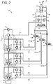
- Fig. 2 illustrates the configuration of a hydraulic circuit 100 for driving the hydraulic cylinder 11 according to the first embodiment of the present invention.
- the hydraulic circuit 100 is disposed in the upperstructure 3 and drives the hydraulic cylinder 11 in response to the operation of the operating lever 5A in the cab 5.
- the hydraulic circuit 100 includes the engine 20 serving as a motor, and the variable displacement hydraulic pumps (three hydraulic pumps according to the present embodiment) 21 to 23 each of which has an input shaft that is coaxial with an output shaft of the engine 20 and is driven by the engine 20, and adjusts the discharge flow rate of each of the hydraulic pumps 21 to 23 to control the speed of the hydraulic cylinder 11 for displacement control.
- the hydraulic circuit 100 also includes a merge circuit 24 on which hydraulic oil discharged from the hydraulic pumps 21 to 23 merges and acts on the hydraulic cylinder 11, switching valves 25 to 27 that switch connection between the hydraulic cylinder 11 and each of the hydraulic pumps 21 to 23 on the merge circuit 24, a speed sensor 28 serving as a speed detector that is electrically connected to the controller 9 and that detects the speed of the hydraulic cylinder 11, and a hydraulic oil tank 29 that stores hydraulic oil to be supplied to the hydraulic pumps 21 to 23.
- a merge circuit 24 on which hydraulic oil discharged from the hydraulic pumps 21 to 23 merges and acts on the hydraulic cylinder 11, switching valves 25 to 27 that switch connection between the hydraulic cylinder 11 and each of the hydraulic pumps 21 to 23 on the merge circuit 24, a speed sensor 28 serving as a speed detector that is electrically connected to the controller 9 and that detects the speed of the hydraulic cylinder 11, and a hydraulic oil tank 29 that stores hydraulic oil to be supplied to the hydraulic pumps 21 to 23.
- a charge pump 31 is connected to the output shaft of the engine 20.
- the charge pump 31 is connected on the discharge side to a flow pass 12.
- the flow pass 12 is connected to the hydraulic oil tank 29 with a relief valve 32 interposed therebetween.
- the relief valve 32 discharges the hydraulic oil in the flow pass 12 into the hydraulic oil tank 29 when the pressure in the flow pass 12 exceeds a predetermined pressure.
- the hydraulic pump 21 includes a pair of input-output ports 21A and 21B via which the hydraulic oil is sucked or discharged, and a two-way tilting swash plate mechanism including a two-way tilting swash plate 21C that adjusts amounts in which the hydraulic oil is sucked and discharged via the input-output ports 21A and 21B and directions in which the hydraulic oil is sucked and discharged via the input-output ports 21A and 21B.
- the hydraulic pump 21 includes a regulator 21D that controls the displacement of the hydraulic pump 21 in a manner in which the tilt angle of the swash plate 21C is adjusted.
- the regulator 21D is electrically connected to the controller 9 and controls suction and discharge directions and suction and discharge flow rates of the input-output ports 21A and 21B of the hydraulic pump 21 by using electric control signals sent from the controller 9.
- a flow pass 14A connected to the head-side oil chamber 11a of the hydraulic cylinder 11 and a flow pass 14B connected to the rod-side oil chamber 11b of the hydraulic cylinder 11 are mounted on the pair of the input-output ports 21A and 21B of the hydraulic pump 21.
- An end of the flow pass 14A is connected to the input-output port 21A of the hydraulic pump 21.
- the other end of the flow pass 14A is connected to a flow pass 13A with the switching valve 25 interposed therebetween, and the flow pass 13A is connected to the head-side oil chamber 11a of the hydraulic cylinder 11.
- An end of the flow pass 14B is connected to the other input-output port 21B of the hydraulic pump 21.
- the other end of the flow pass 14B is connected to a flow pass 13B with the switching valve 25 interposed therebetween, and the flow pass 13B is connected to the rod-side oil chamber 11b of the hydraulic cylinder 11.
- the hydraulic cylinder 11 and the hydraulic pump 21 are connected to each other in a closed circuit manner with the flow passes 13A, 13B, 14A, and 14B and the switching valve 25 interposed therebetween, and a closed circuit 241 on which the hydraulic cylinder 11 is directly driven by the hydraulic pump 21 is formed.
- the closed circuit 241 includes a flushing valve 33 that connects a low-pressure-side flow pass of the flow passes 13A and 13B to the flow pass 12 and that discharges the hydraulic oil in the low-pressure-side flow pass into the flow pass 12, relief valves 41 and 42 that discharge the hydraulic oil in the flow passes 13A and 13B into the flow pass 12 when pressures in the flow passes 13A and 13B exceed a predetermined pressure, and make-up valves 43 and 44 that supply the hydraulic oil discharged from the charge pump 31 from the flow pass 12 to the flow passes 13A and 13B when the pressures in the flow passes 13A and 13B become less than a predetermined pressure.
- the closed circuit 241 also includes relief valves 51 and 52 that discharge the hydraulic oil in the flow passes 14A and 14B into the flow pass 12 when the pressures in the flow passes 14A and 14B exceed a predetermined pressure, make-up valves 53 and 54 that supply the hydraulic oil discharged from the charge pump 31 from the flow pass 12 to the flow passes 14A and 14B when the pressures in the flow passes 14A and 14B become less than a predetermined pressure, and pressure sensors 55 and 56 that are mounted on the flow passes 14A and 14B near the input-output ports 21A and 21B of the hydraulic pump 21 and that serve as pressure detectors that detect the pressures in the flow passes 14A and 14B, that is, suction and discharge pressures of the hydraulic pump 21.
- the pressure sensors 55 and 56 are electrically connected to the controller 9.
- a closed circuit 242 and a closed circuit 243 that include the hydraulic pump 22 and the hydraulic pump 23 are the same as the above closed circuit 241, and a description thereof is omitted.
- the switching valves 26 and 27 are the same as the above switching valve 25, and a description thereof is omitted.
- the controller 9 includes a target-speed-calculating section 91 that calculates a target speed of the hydraulic cylinder 11 to be moved on the basis of the manipulated variable of the operating lever 5A, a target-driving-pressure-calculating section 92 that calculates a target driving pressure for driving the hydraulic cylinder 11 on the basis of the speed of the hydraulic cylinder 11 that is detected by the speed sensor 28 and the target speed calculated by the target-speed-calculating section 91, and a pump-switching valve control section 93 that controls operation of the hydraulic pumps 21 to 23 and the switching valves 25 to 27 in accordance with the pressures of the input-output ports 21A to 23A and 21B to 23B that are detected by the pressure sensors 55, 56, 65, 66, 75, and 76 and the target driving pressure calculated by the target-driving-pressure-calculating section 92.
- the target-speed-calculating section 91 stores the relationship between the manipulated variable of the operating lever 5A and the target speed of the hydraulic cylinder 11 in advance.
- the target-speed-calculating section 91 calculates the target speed of the hydraulic cylinder 11 on the basis of the above relationship in a manner in which an operation signal of the operating lever 5A is inputted and the manipulated variable of the operating lever 5A is used in the above relationship.
- the hydraulic cylinder 11 expands, and when the sign of the speed of the hydraulic cylinder 11 is negative, the hydraulic cylinder 11 contracts.
- the pump-switching valve control section 93 includes a pump-selecting section 931 that selects at least one of the hydraulic pumps for driving the hydraulic cylinder 11 from the hydraulic pumps 21 to 23, a target-discharge-flow-rate-calculating section 932 that calculates the target discharge flow rate of each of the hydraulic pumps 21 to 23 in accordance with the result of selection by the pump-selecting section 931, and a displacement-command-value-calculating section 933 that calculates a displacement command value corresponding to the target discharge flow rate of each of the hydraulic pumps 21 to 23 that is calculated by the target-discharge-flow-rate-calculating section 932, that is, the target command value of the discharge flow rate of each of the hydraulic pumps 21 to 23.
- the pump-selecting section 931 sends, to the switching valve(s) corresponding to the at least one of the hydraulic pumps selected from the switching valves 25 to 27, a control signal to cause the switch position thereof to be maintained at the open position, and sends, to the other switching valve(s), a control signal to cause the switch position thereof to be maintained at the close position.
- a process of selection from the hydraulic pumps 21 to 23 by the pump-selecting section 931 will be described in detail later.
- the hydraulic pump 21 when the sign of the target discharge flow rate of the hydraulic pump 21 is positive, the hydraulic pump 21 sucks the hydraulic oil from the input-output port 21B and discharges the hydraulic oil from the input-output port 21A, and when the sign of the target discharge flow rate of the hydraulic pump 21 is negative, the hydraulic pump 21 sucks the hydraulic oil from the input-output port 21A and discharges the hydraulic oil from the input-output port 21B.
- the pump-switching valve control section 93 sends a control signal of the displacement command value calculated by the displacement-command-value-calculating section 933 to the regulators 21D to 23D of the corresponding hydraulic pumps 21 to 23 and sends the result of selection by the pump-selecting section 931, the result of calculation by the target-discharge-flow-rate-calculating section 932, and the result of calculation by the displacement-command-value-calculating section 933 to a volumetric-transfer-efficiency-calculating section 94 described later.
- the pump-switching valve control section 93 thus functions as a target-command-value-obtaining section that obtains the target command value of the discharge flow rate of each of the hydraulic pumps 21 to 23.
- the controller 9 includes the volumetric-transfer-efficiency-calculating section 94 that calculates a volumetric transfer efficiency ⁇ C representing the transfer efficiency of the hydraulic oil between the hydraulic cylinder 11 and the hydraulic pumps 21 to 23 on the basis of the speed of the hydraulic cylinder 11 that is detected by the speed sensor 28, the rotational speed of the hydraulic pumps 21 to 23 that is detected by the rotational speed sensor 20A, the result of selection by the pump-selecting section 931, the result of calculation by the target-discharge-flow-rate-calculating section 932, and the result of calculation by the displacement-command-value-calculating section 933.
- the controller 9 also includes an abnormality decision section 95 that decides whether any one of the hydraulic pumps 21 to 23 has abnormality such as a malfunction or wear and tear on the basis of the volumetric transfer efficiency ⁇ C calculated by the volumetric-transfer-efficiency-calculating section 94, and an information control section 96 that causes the monitor 5B to display the result of decision when the abnormality decision section 95 decides that any one of the hydraulic pumps 21 to 23 is abnormal.
- an abnormality decision section 95 that decides whether any one of the hydraulic pumps 21 to 23 has abnormality such as a malfunction or wear and tear on the basis of the volumetric transfer efficiency ⁇ C calculated by the volumetric-transfer-efficiency-calculating section 94
- an information control section 96 that causes the monitor 5B to display the result of decision when the abnormality decision section 95 decides that any one of the hydraulic pumps 21 to 23 is abnormal.
- a process of calculating the volumetric transfer efficiency ⁇ C by using the volumetric-transfer-efficiency-calculating section 94 and a process of deciding whether any one of the hydraulic pumps 21 to 23 is abnormal by using the abnormality decision section 95 will be described in detail below.
- the switching valve 25 is switched to the open position 25A
- the switching valves 26 and 27 are switched to a close position 26B and 27B respectively, and the hydraulic pump 21 alone drives the hydraulic cylinder 11.
- the hydraulic pump 22 or 23 alone drives the hydraulic cylinder 11 and a duplicated description is omitted.
- the hydraulic circuit 100 is a system for displacement control as described above. Accordingly, regarding the flow rate of the hydraulic oil discharged from the hydraulic pump 21, all of the hydraulic oil except for a small oil leak across the closed circuit 241 flows into the hydraulic cylinder 11 unless the pressure in the hydraulic circuit 100 exceeds pressures set to the relief valves 41, 42, 51, and 52 and the hydraulic oil flows into the flow pass 12.
- the pressures in the flow passes 13A, 13B, 14A, and 14B that connect the hydraulic cylinder 11 and the hydraulic pump 21 to each other are less than the pressures set to the relief valves 41, 42, 51, and 52 and are higher than the pressure in the flow pass 12 upstream of the make-up valves 43, 44, 53, and 54, and that the hydraulic oil does not flow between the flow passes 13A, 13B, 14A, and 14B and the flow pass 12.
- the speed V of the hydraulic cylinder 11 is proportional to the displacement command value C of the hydraulic pump 21.
- the flow rate Q IN of the hydraulic oil flowing into the hydraulic cylinder 11 is less than the theoretical value Q OUT of the discharge flow rate of the hydraulic pump 21 and varies because of an effect on the volumetric efficiency due to, mainly, a leak in the hydraulic pump 21 itself and an effect of the above leak across the closed circuit 241.
- the volumetric-transfer-efficiency-calculating section 94 calculates the volumetric transfer efficiency ⁇ C in a manner in which the pressure-receiving area A of the piston 11B of the hydraulic cylinder 11 that is stored in the controller 9 in advance, the speed V of the hydraulic cylinder 11 that is detected by the speed sensor 28, the rotational speed R of the hydraulic pump 21 that is detected by the rotational speed sensor 20A, and the displacement command value C of the hydraulic pump 21 that is calculated by the displacement-command-value-calculating section 933 are substituted in the numerical formula (5).
- the theoretical value of the volumetric transfer efficiency ⁇ C calculated by the volumetric-transfer-efficiency-calculating section 94 is 1.
- the volumetric transfer efficiency ⁇ C is less than 1, the smaller the volumetric transfer efficiency ⁇ C , the more the speed of the hydraulic cylinder 11 that is equal to the displacement command value is difficult to obtain. This means that the performance of the hydraulic pump 21 is reduced.
- the volumetric transfer efficiency ⁇ C is less than the theoretical value because of a problem such as the above leak even when the hydraulic pumps 21 to 23 normally operate.
- the abnormality decision section 95 decides that the hydraulic pump 21 is not abnormal when the volumetric transfer efficiency ⁇ C calculated by the volumetric-transfer-efficiency-calculating section 94 falls within a predetermined normal value range, and decides that the hydraulic pump 21 is abnormal when the volumetric transfer efficiency ⁇ C calculated by the volumetric-transfer-efficiency-calculating section 94 falls outside the predetermined normal value range.
- the discharge flow rate of the hydraulic pump 21 can be equal to or more than the discharge flow rate corresponding to the displacement command value.
- the volumetric transfer efficiency ⁇ C calculated by the volumetric-transfer-efficiency-calculating section 94 is more than the normal value.
- the normal value range it is only necessary for the normal value range to be accurately grasped to such a degree that precision required for the result of decision whether the hydraulic pump 21 is abnormal is obtained as in the case where the volumetric transfer efficiency ⁇ C of the hydraulic pump 21 decreases.
- the volumetric transfer efficiency ⁇ C calculated by the volumetric-transfer-efficiency-calculating section 94 exceeds 1, which is the theoretical value, the hydraulic pump 21 surely has abnormality, the abnormality that the hydraulic pump 21 surely has can be decided even when the normal value range is not accurately gasped.
- how many hydraulic pumps of the hydraulic pumps 21 to 23 are used to drive the hydraulic cylinders 11 and which hydraulic pump is used can be selected in a manner in which the pump-selecting section 931 switches the switching valves 25 to 27 to the open positions 25A to 27A, or to the close positions 25B to 27B.
- the volumetric transfer efficiency ⁇ C at this time is expressed as the following numerical formula (6), wherein C 1 , C 2 , and C 3 are the displacement command values of the hydraulic pumps 21 to 23.
- the volumetric transfer efficiency ⁇ C calculated by the numerical formula (6) is defined as the ratio of the flow rate of the hydraulic oil flowing into the hydraulic cylinder 11 to the sum of the discharge flow rate of each of the hydraulic pumps 21 to 23 by using the sum of the displacement command values C 1 , C 2 , and C 3 of the hydraulic pumps 21 to 23.
- the presence or absence of abnormality of each of the hydraulic pumps 21 to 23 cannot be decided by using only the volumetric transfer efficiency ⁇ C .
- information about the volumetric transfer efficiency ⁇ C in different states of the hydraulic oil that is discharged from the hydraulic pumps 21 to 23 and that merges, that is, in different states of connection between the hydraulic cylinder 11 and the hydraulic pumps 21 to 23 is used to identify the hydraulic pump that causes a reduction of the volumetric transfer efficiency ⁇ C , and the presence or absence of abnormality of this hydraulic pump is decided.
- the first embodiment of the present invention provides an abnormality-diagnosis-mode-setting section that sets an abnormality diagnosis mode in which abnormality of each of the hydraulic pumps 21 to 23 is diagnosed.
- the abnormality-diagnosis-mode-setting section includes an abnormality-diagnosis-mode switch 5C that is disposed, for example, in the cab 5 and that is pushed by an operator.
- the controller 9 causes the abnormality decision section 95 to decide whether the one of the hydraulic pumps is abnormal.
- the volumetric transfer efficiency ⁇ C between the hydraulic cylinder 11 and the one of the hydraulic pumps can be calculated even in a system that drives the hydraulic cylinder 11 in one system by using the hydraulic oil that is discharged from the hydraulic pumps 21 to 23 and that merges as in the hydraulic circuit 100 according to the first embodiment of the present invention.
- the volumetric-transfer-efficiency-calculating section 94 can calculate the volumetric transfer efficiency ⁇ C by using the numerical formula (5) as in the case of driving the hydraulic cylinder 11 by using only the hydraulic pump 21. Accordingly, the controller 9 enables the presence or absence of abnormality of each of the hydraulic pumps 21 to 23 to be individually decided in a manner in which the pump-selecting section 931 selects one of the hydraulic pumps 21 to 23 to change the hydraulic pump to be connected to the hydraulic cylinder 11 in turns.
- abnormality of each of the hydraulic pumps 21 to 23 can be detected without affecting normal operation of the hydraulic excavator 1.
- the hydraulic cylinder 11 slowly moves at a discharge flow rate assigned to one of the hydraulic pumps 21 to 23 during the operation of the hydraulic excavator 1 even in a system that drives the hydraulic cylinder 11 in one system by using the hydraulic oil that is discharged from the hydraulic pumps 21 to 23 and that merges as in the hydraulic circuit 100.
- the abnormality decision section 95 decides the presence or absence of abnormality of each of the hydraulic pumps 21 to 23 by using the volumetric transfer efficiency ⁇ C obtained with such timing.
- the abnormality decision section 95 cannot decide the presence or absence of abnormality of the other hydraulic pumps, and accordingly, it is necessary to change how to connect the hydraulic cylinder 11.
- the abnormality decision section 95 can decide the presence or absence of abnormality of each of the hydraulic pumps 21 to 23 during the operation of the hydraulic excavator 1 in a manner in which the pump-selecting section 931 changes the hydraulic pump that is used for the slow movement of the hydraulic cylinder 11 each time.
- the hydraulic circuit 100 is a system in which the hydraulic cylinder 11 in one system is driven by using the hydraulic oil that is discharged from the hydraulic pumps 21 to 23 and that merges, and accordingly, there are several combinations of the hydraulic cylinder 11 and at least one of the hydraulic pumps 21 to 23 connected thereto when the number of the at least one of the hydraulic pumps 21 to 23 connected to the hydraulic cylinder 11 is less than the maximum number of connections (referred to below as the maximum connection number for convenience) that the switching valves 25 to 27 permit, that is, 2 or less. Accordingly, in the case where the volumetric transfer efficiency ⁇ C has different values for every combination of the hydraulic cylinder 11 and at least one of the hydraulic pumps 21 to 23 connected thereto, which hydraulic pump causes the different values can be identified.
- a volumetric transfer efficiency ⁇ C12 between the hydraulic cylinder 11 and the hydraulic pumps 21 and 22 is expressed as the following numerical formula (7).
- ⁇ C 12 A ⁇ V C 1 + C 2 ⁇ R
- a volumetric transfer efficiency ⁇ C23 between the hydraulic cylinder 11 and the hydraulic pumps 22 and 23 is expressed as the following numerical formula (8).
- ⁇ C 23 A ⁇ V C 2 + C 3 ⁇ R
- a volumetric transfer efficiency ⁇ C123 between the hydraulic cylinder 11 and the hydraulic pumps 21 to 23 is expressed as the following numerical formula (10) .
- ⁇ C 123 A ⁇ V C 1 + C 2 + C 3 ⁇ R
- the controller 9 controls the switching operation of the switching valves 25 to 27 such that the combination of the hydraulic cylinder 11 and at least one of the hydraulic pumps 21 to 23 connected thereto is changed.
- the pump-selecting section 931 selects at least one hydraulic pump for driving the hydraulic cylinder 11 from the hydraulic pumps 21 to 23 such that all of the combinations of the hydraulic cylinder 11 and at least one of the hydraulic pumps 21 to 23 connected thereto are selected in turns.
- the controller 9 may have a rule under which the combination of the hydraulic cylinder 11 and at least one of the hydraulic pumps 21 to 23 connected thereto is randomly changed whenever the number N of the at least one of the hydraulic pumps 21 to 23 connected to the hydraulic cylinder 11 increases or decreases, or a rule under which, when the number N of connections increases, the switching valve(s) corresponding to at least one of the hydraulic pumps connected before the number N of connections increases is maintained at the open position, and the switching valve(s) corresponding to the other hydraulic pump(s) is switched from the close position to the open position in order to reduce the number of the switching valves 25 to 27 that are switched by the pump-selecting section 931.
- the information control section 96 controls and causes the monitor 5B to display, for example, a massage to an operator in the cab 5 to prompt the setting of the abnormality diagnosis mode. Consequently, the controller 9 according to the first embodiment of the present invention identifies a hydraulic pump of the hydraulic pumps 21 to 23 that presumably has abnormality, and the abnormality of the hydraulic pump to be diagnosed can be accurately detected in the abnormality diagnosis mode.
- a process of detecting abnormality of each of the hydraulic pumps 21 to 23 by using the controller 9 according to the first embodiment of the present invention will now be described in detail with reference to the flowchart in Fig. 5 .
- the process of detecting abnormality of each of the hydraulic pumps 21 to 23 is always performed while the hydraulic excavator 1 operates.
- the controller 9 determines the thresholds Qa and Va that are compared to the result of calculation by the target-discharge-flow-rate-calculating section 932 and the result of detection by the speed sensor 28 to start the process of detecting abnormality of each of the hydraulic pumps 21 to 23 only when the absolute value of the target discharge flow rate of each of the hydraulic pumps 21 to 23 and the absolute value of the speed of the hydraulic cylinder 11 are equal to or more than the thresholds Qa and Va.
- This enables the obtained volumetric transfer efficiency ⁇ C to appropriately reflect the state of each of the hydraulic pumps 21 to 23 and enables the accurate result of detection to be obtained.
- the thresholds Qa and Va are determined in accordance with the accuracy required for the result of detection of abnormality of each of the hydraulic pumps 21 to 23 and the rapidity of the process of detection.
- the range of the volumetric transfer efficiency ⁇ C that is determined as the normal value range can be narrow in a manner in which the thresholds Qa and Va are determined by using an approximation to the maximum speed of the hydraulic cylinder 11 that reaches under a very light load as a criterion, and the accuracy of the result of detecting abnormality of each of the hydraulic pumps 21 to 23 can be improved.
- this reduces frequency at which the hydraulic cylinder 11 meets the speed of criteria during the operation of the hydraulic excavator 1.
- the volumetric transfer efficiency ⁇ C greatly varies due to the dynamic characteristics of the hydraulic system and the control system in the hydraulic circuit 100.
- a specific example of the variation in the volumetric transfer efficiency ⁇ C due to the dynamic characteristics of the hydraulic system and the control system will now be described in detail with reference to Fig. 6 and Fig. 7 .
- the response of the speed of the hydraulic cylinder 11 is delayed, and the hydraulic cylinder 11 is still at rest right after an operator operates the operating lever 5A to increase the target discharge flow rate of each of the hydraulic pumps 21 to 23 in a state where the target discharge flow rate of each of the hydraulic pumps 21 to 23 is 0 and the hydraulic cylinder 11 is at rest.
- the volumetric transfer efficiency ⁇ C calculated by the volumetric-transfer-efficiency-calculating section 94 is 0 according to the numerical formula (6).
- the response of the speed of the hydraulic cylinder 11 is delayed, and the hydraulic cylinder 11 is still moving right after an operator operates the operating lever 5A to adjust the target discharge flow rate of each of the hydraulic pumps 21 to 23 to be 0 in a state where the hydraulic cylinder 11 moves at a speed corresponding to the target discharge flow rate of each of the hydraulic pumps 21 to 23.
- the volumetric transfer efficiency ⁇ C calculated by the volumetric-transfer-efficiency-calculating section 94 is infinite according to the numerical formula (6).
- the abnormality decision section 95 of the controller 9 receives the result of calculation by the volumetric-transfer-efficiency-calculating section 94 and assumes whether the volumetric transfer efficiency ⁇ C of any one of the combinations that is calculated by the volumetric-transfer-efficiency-calculating section 94 decreases (S506). In the case where the abnormality decision section 95 decides that the volumetric transfer efficiency ⁇ C of each combination does not decrease (S506 / No) at this time, the processes from S501 are repeated.
- the abnormality decision section 95 decides that the volumetric transfer efficiency ⁇ C of one of the combinations decreases (S506 / Yes) at S506, a hydraulic pump of the hydraulic pumps 21 to 23 that presumably is abnormal is identified by using the volumetric transfer efficiency ⁇ C, and the information control section 96 of the controller 9 displays, for example, a massage on the monitor 5B to prompt the setting of the abnormality diagnosis mode.
- the controller 9 decides whether the abnormality diagnosis mode is set by using the abnormality-diagnosis-mode switch 5C (S507). In the case where the controller 9 decides the abnormality diagnosis mode is not set (S507 / No) at this time, the processes from S501 are repeated.
- the pump-switching valve control section 93 switches the switching valves 25 to 27 such that the hydraulic cylinder 11 is connected to the hydraulic pump identified by the abnormality decision section 95, that is, the hydraulic pump to be diagnosed in the abnormality diagnosis mode, and subsequently, the volumetric-transfer-efficiency-calculating section 94 calculates the volumetric transfer efficiency ⁇ C between the hydraulic cylinder 11 and the hydraulic pump to be diagnosed (S508).
- the abnormality decision section 95 receives the result of calculation by the volumetric-transfer-efficiency-calculating section 94 and checks whether the volumetric transfer efficiency ⁇ C calculated by the volumetric-transfer-efficiency-calculating section 94 falls outside the predetermined normal value range (S509). In the case where the abnormality decision section 95 ascertains that the volumetric transfer efficiency ⁇ C falls within the normal value range (S509 / No) at this time, the abnormality decision section 95 decides that the hydraulic pump to be diagnosed has no abnormality, and the processes from S501 are repeated.
- the abnormality decision section 95 determines that the volumetric transfer efficiency ⁇ C falls outside the normal value range (S509 / Yes) at S509, the abnormality decision section 95 decides that the hydraulic pump to be diagnosed is abnormal, the information control section 96 displays, for example, a massage on the monitor 5B to inform that the hydraulic pump is abnormal (S510), and the processes from S501 are repeated.
- the volumetric transfer efficiency ⁇ C calculated by the volumetric-transfer-efficiency-calculating section 94 exceeds the upper limit of the normal value, and information that any one of the hydraulic pumps 21 to 23 is abnormal is displayed on the monitor 5B. This enables an operator in the cab 5 to grasp abnormality of each of the hydraulic pumps 21 to 23 in an early stage and enables the operator to rapidly deal with the abnormality of each of the hydraulic pumps 21 to 23.
- the controller of the hydraulic excavator 1 according to the first embodiment of the present invention thus reduces the equipment cost, enables abnormality of each of the hydraulic pumps 21 to 23 including control equipment such as the regulators 21D to 23D to be accurately detected, achieves excellent economy, and improves reliability of the process of detecting abnormality of each of the hydraulic pumps 21 to 23.
- a second embodiment of the present invention differs from the above first embodiment in that, although the volumetric-transfer-efficiency-calculating section 94 according to the first embodiment defines the volumetric transfer efficiency ⁇ C as the ratio of the flow rate of the hydraulic oil flowing into the hydraulic cylinder 11 to the discharge flow rate of the hydraulic pump 21 and calculates the volumetric transfer efficiency ⁇ C on the discharge side of the hydraulic pumps 21 to 23 in the closed circuits 241 to 243, the volumetric-transfer-efficiency-calculating section 94 according to the second embodiment also calculates the volumetric transfer efficiency ⁇ C on the suction side of the hydraulic pumps 21 to 23 in the closed circuits 241 to 243.
- a process of calculating the volumetric transfer efficiency ⁇ C by the volumetric-transfer-efficiency-calculating section 94 according to the second embodiment of the present invention will be described in detail below.
- the switching valve 25 is switched to the open position 25A
- the switching valves 26 and 27 are switched to the close positions 26B and 27B, and the hydraulic pump 21 alone drives the hydraulic cylinder 11.
- the hydraulic pump 22 or 23 alone drives the hydraulic cylinder 11, and a duplicated description is omitted.
- the hydraulic oil discharged from the charge pump 31 is supplied to the inside of the flow pass on the suction side of the hydraulic pump 21 via the make-up valves 43, 44, 53, and 54.
- the result of calculation of the volumetric transfer efficiency ⁇ C on the suction side of the hydraulic pump 21 by the volumetric-transfer-efficiency-calculating section 94 does not accurately represent the state of suction by the hydraulic pump 21.
- the pressure of the hydraulic pump 21 on the suction side is equal to or more than the pressures set to the make-up valves 43, 44, 53, and 54, and the hydraulic oil discharged from the charge pump 31 does not flow into the suction side of the hydraulic pump 21 via the make-up valves 43, 44, 53, and 54. Accordingly, the flow rate of the hydraulic oil flowing from the hydraulic cylinder 11 corresponds to the suction flow rate of the hydraulic pump 21. In this state, the speed of the hydraulic cylinder 11 is controlled by using the suction flow rate of the hydraulic pump 21.
- the normal value range of the volumetric transfer efficiency ⁇ C on the suction side of the hydraulic pump 21 may be determined in the same manner as the normal value range of the volumetric transfer efficiency ⁇ C on the discharge side of the hydraulic pump 21.
- the volumetric transfer efficiency ⁇ C on the suction side of the hydraulic pump 21 is actually measured in advance to determine the normal value range of the volumetric transfer efficiency ⁇ C apart from the normal value range of the volumetric transfer efficiency ⁇ C on the discharge side of the hydraulic pump 21. This enables the abnormality decision section 95 to more accurately decide the presence or absence of abnormality of the hydraulic pump 21.
- the volumetric-transfer-efficiency-calculating section 94 first receives the values detected by the pressure sensors 55 and 56 to decide whether the difference between the pressures of the input-output ports 21A and 21B of the hydraulic pump 21 that are detected by the pressure sensors 55 and 56 is a positive value (S801).
- the volumetric-transfer-efficiency-calculating section 94 decides that the difference between the pressures of the input-output ports 21A and 21B of the hydraulic pump 21 is a positive value (S801 / Yes) at this time, the result of calculation by the target-discharge-flow-rate-calculating section 932 is inputted from the pump-switching valve control section 93, and whether the target discharge flow rate calculated by the target-discharge-flow-rate-calculating section 932 is a positive value is decided (S802).
- the hydraulic pump 21 sucks the hydraulic oil from the input-output port 21B and discharges the hydraulic oil from the input-output port 21A.
- the hydraulic pump 21 sucks the hydraulic oil from the input-output port 21A and discharges the hydraulic oil from the input-output port 21B.
- the volumetric-transfer-efficiency-calculating section 94 decides that the difference between the pressures of the input-output ports 21A and 21B of the hydraulic pump 21 is a negative value (S801 / No) at S801, the result of calculation by the target-discharge-flow-rate-calculating section 932 is inputted from the pump-switching valve control section 93, and whether the target discharge flow rate calculated by the target-discharge-flow-rate-calculating section 932 is a positive value is decided (S805).
- the volumetric-transfer-efficiency-calculating section 94 decides that the target discharge flow rate calculated by the target-discharge-flow-rate-calculating section 932 is a positive value (S805 / Yes) at S805, the volumetric transfer efficiency ⁇ C is calculated by using the numerical formula (12) (S804) to finish the process of calculating the volumetric transfer efficiency ⁇ C.
- the target discharge flow rate calculated by the target-discharge-flow-rate-calculating section 932 is decided to be a negative value (S805 / No) at S805
- the volumetric transfer efficiency ⁇ C is calculated by using the numerical formula (5) (S803) to finish the process of calculating the volumetric transfer efficiency ⁇ C.
- the volumetric transfer efficiency ⁇ C in the case where the hydraulic pumps 21 to 23 drive the hydraulic cylinder 11 is expressed as the following numerical formula (13). Also in this case, the process of calculating the volumetric transfer efficiency ⁇ C by the volumetric-transfer-efficiency-calculating section 94 is performed by using the following numerical formula (13) in the same manner as in the above case of driving the hydraulic cylinder 11 by the hydraulic pump 21.
- the volumetric-transfer-efficiency-calculating section 94 can calculate not only the volumetric transfer efficiency ⁇ C on the discharge side of the hydraulic pumps 21 to 23 but also the volumetric transfer efficiency ⁇ C on the suction side of the hydraulic pumps 21 to 23 in a manner in which different definitions of the volumetric transfer efficiency ⁇ C are appropriately used depending on the fact that the hydraulic pumps 21 to 23 discharge the hydraulic oil into the high-pressure-side flow pass of the flow passes 14A to 16A and 14B to 16B, or the hydraulic pumps 21 to 23 suck the hydraulic oil from the high-pressure-side flow pass of the flow passes 14A to 16A and 14B to 16B. In this way, even when the operation of each of the hydraulic pumps 21 to 23 in one direction is normal but the operation thereof in the other direction is abnormal, such a state can be accurately detected as abnormality of each of the hydraulic pumps 21 to 23.
- the configuration of a third embodiment of the present invention is based on the configuration of the above second embodiment but differs from that of the second embodiment in the following features. That is, the volumetric-transfer-efficiency-calculating section 94 according to the third embodiment of the present invention calculates either the ratio of the flow rate of the hydraulic oil flowing into the hydraulic cylinder 11 to the discharge flow rate of each of the hydraulic pumps 21 to 23 or the ratio of the suction flow rate of each of the hydraulic pumps 21 to 23 to the flow rate of the hydraulic oil flowing from the hydraulic cylinder 11 as the volumetric transfer efficiency ⁇ C in accordance with a combination of a magnitude relationship between the pressures of the input-output ports 21A to 23A and 21B to 23B of each of the hydraulic pumps 21 to 23 that are detected by the pressure sensors 55, 56, 65, 66, 75, and 76 and a direction of movement of the hydraulic cylinder 11 that is represented by the speed of the hydraulic cylinder 11 that is detected by the speed sensor 28.
- the other configuration of the third embodiment is the same as the configuration of the second embodiment.
- the volumetric-transfer-efficiency-calculating section 94 decides that the difference between the pressures of the input-output ports 21A and 21B of the hydraulic pump 21 is a positive value (S801 / Yes) at S801, the value detected by the speed sensor 28 is inputted, and whether the speed of the hydraulic cylinder 11 that is detected by the speed sensor 28 is a positive value is decided (S901). In the case where the volumetric-transfer-efficiency-calculating section 94 decides that the speed of the hydraulic cylinder 11 is a positive value (S901 / Yes) at this time, the process at S803 is performed.
- the volumetric-transfer-efficiency-calculating section 94 decides that the speed of the hydraulic cylinder 11 is a negative value (S901 / No) at S901, the process at S804 is performed.
- the sign of the speed of the hydraulic cylinder 11 is positive, the hydraulic cylinder 11 expands, and when the sign of the speed of the hydraulic cylinder 11 is negative, the hydraulic cylinder 11 contracts.
- the volumetric-transfer-efficiency-calculating section 94 decides that the difference between the pressures of the input-output ports 21A and 21B of the hydraulic pump 21 is a negative value (S801 / No) at S801, the value detected by the speed sensor 28 is inputted, and whether the speed of the hydraulic cylinder 11 that is detected by the speed sensor 28 is a positive value is decided (S902). In the case where the volumetric-transfer-efficiency-calculating section 94 decides that the speed of the hydraulic cylinder 11 is a positive value (S902 / Yes) at this time, the process at S804 is performed. In the case where the volumetric-transfer-efficiency-calculating section 94 decides that the speed of the hydraulic cylinder 11 is a negative value (S902 / No) at S902, the process at S803 is performed.
- the different numerical formulas are used to calculate the volumetric transfer efficiency ⁇ c even under the same conditions between the case where the volumetric-transfer-efficiency-calculating section 94 operates on the basis of the target discharge flow rate of each of the hydraulic pumps 21 to 23 according to the second embodiment and the case where the volumetric-transfer-efficiency-calculating section 94 operates on the basis of the direction of movement of the hydraulic cylinder 11 according to the third embodiment.
- the volumetric transfer efficiency ⁇ c calculated by the volumetric-transfer-efficiency-calculating section 94 is a negative value, and the volumetric transfer efficiency ⁇ c apparently falls outside the normal value range. For this reason, abnormality of each of the hydraulic pumps 21 to 23 can be accurately detected.
- the volumetric-transfer-efficiency-calculating section 94 appropriately uses different definitions of the volumetric transfer efficiency ⁇ c depending on the fact that the hydraulic oil flows into the hydraulic cylinder 11 from the high-pressure-side flow pass of the flow passes 13A and 13B or the hydraulic oil flows into the high-pressure-side flow pass of the flow passes 13A and 13B from the hydraulic cylinder 11, and accordingly, the same effects as in the above second embodiment can be achieved.
- the speed of the hydraulic cylinder 11 is controlled in a manner in which the discharge flow rate of each of the hydraulic pumps 21 to 23 is adjusted for displacement control.
- the present invention is not limited thereto.
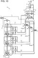
- the flow rate of the hydraulic oil flowing into the hydraulic cylinder 11 is controlled by using only the discharge flow rate of each of the hydraulic pumps 21 to 23, but the flow rate of the hydraulic oil flowing from the hydraulic cylinder 11 is controlled by using not only the suction flow rate of each of the hydraulic pumps 21 to 23 but also a proportional valve 81 the opening area of which is adjusted in accordance with control signals from the controller 9 as illustrated in Fig. 10 .
- the embodiments of the present invention can be used for a hydraulic circuit 101 including the proportional valve 81 disposed in a flow pass 17 branched from the flow pass 13A.
- the volumetric transfer efficiency ⁇ c is preferably defined in consideration for a command value to the proportional valve 81 in addition to the target discharge flow rate of each of the hydraulic pumps 21 to 23 and the speed of the hydraulic cylinder 11 with the flow rate of hydraulic oil that flows from the proportional valve 81 into the hydraulic oil tank 29 included.
- the number of the hydraulic pumps is 3.
- the present invention is not limited thereto.
- the number of the hydraulic pumps may be 2, or 4 or more.
- the abnormality decision section 95 decides the presence or absence of abnormality of each hydraulic pump from the volumetric transfer efficiency ⁇ c obtained while one of the hydraulic pumps alone drives the hydraulic cylinder 11 as in the case where the abnormality diagnosis mode is set by using the abnormality-diagnosis-mode switch 5C.
- the hydraulic excavator 1 includes the speed sensor 28 that can directly detect the speed of the hydraulic cylinder 11.
- the present invention is not limited thereto.
- the speed of the hydraulic cylinder 11 may be detected in a manner in which a displacement of the hydraulic cylinder 11 is detected by using a displacement sensor with which a work machine such as the hydraulic excavator 1 is typically equipped instead of the speed sensor 28 or the angle of a joint of the front working device 4, in which the hydraulic cylinder 11 is driven, is detected by an angle sensor and converted into the displacement of the hydraulic cylinder 11, and a time derivative of the displacement of the hydraulic cylinder 11 is calculated.
- the hydraulic excavator 1 includes the hydraulic cylinder 11 serving as the actuator, and the variable displacement hydraulic pumps 21 to 23 that drive the hydraulic cylinder 11.
- the present invention is not limited thereto.
- the types of the actuator and the hydraulic pumps may be appropriately changed.
- the actuator may be a single rod cylinder, a double rod cylinder, or one of various types of hydraulic motors such as a drive motor and a swing motor.
- the hydraulic pumps may be, for example, variable displacement vane pumps.
Landscapes
- Engineering & Computer Science (AREA)
- General Engineering & Computer Science (AREA)
- Mining & Mineral Resources (AREA)
- Civil Engineering (AREA)
- Structural Engineering (AREA)
- Mechanical Engineering (AREA)
- Physics & Mathematics (AREA)
- General Physics & Mathematics (AREA)
- Fluid Mechanics (AREA)
- Fluid-Pressure Circuits (AREA)
- Operation Control Of Excavators (AREA)
- Control Of Positive-Displacement Pumps (AREA)
Applications Claiming Priority (2)
| Application Number | Priority Date | Filing Date | Title |
|---|---|---|---|
| JP2015256096A JP6510396B2 (ja) | 2015-12-28 | 2015-12-28 | 作業機械 |
| PCT/JP2016/075240 WO2017115493A1 (fr) | 2015-12-28 | 2016-08-29 | Machine de travail |
Publications (3)
| Publication Number | Publication Date |
|---|---|
| EP3399190A1 true EP3399190A1 (fr) | 2018-11-07 |
| EP3399190A4 EP3399190A4 (fr) | 2019-08-14 |
| EP3399190B1 EP3399190B1 (fr) | 2021-08-11 |
Family
ID=59225818
Family Applications (1)
| Application Number | Title | Priority Date | Filing Date |
|---|---|---|---|
| EP16881473.9A Active EP3399190B1 (fr) | 2015-12-28 | 2016-08-29 | Machine de travail |
Country Status (5)
| Country | Link |
|---|---|
| US (1) | US10745887B2 (fr) |
| EP (1) | EP3399190B1 (fr) |
| JP (1) | JP6510396B2 (fr) |
| CN (1) | CN107923387B (fr) |
| WO (1) | WO2017115493A1 (fr) |
Cited By (1)
| Publication number | Priority date | Publication date | Assignee | Title |
|---|---|---|---|---|
| US20180238028A1 (en) * | 2015-12-28 | 2018-08-23 | Hitachi Construction Machinery Co., Ltd. | Work machine |
Families Citing this family (9)
| Publication number | Priority date | Publication date | Assignee | Title |
|---|---|---|---|---|
| JP6752183B2 (ja) * | 2017-09-07 | 2020-09-09 | 日立建機株式会社 | 油圧作業機械 |
| DE102019208086A1 (de) * | 2019-06-04 | 2020-12-10 | Robert Bosch Gmbh | Hydraulisches Antriebssystem mit zwei Pumpen und Energierückgewinnung |
| US11731690B2 (en) * | 2020-02-12 | 2023-08-22 | Caterpillar Inc. | Redundant steering system and machines and methods thereof |
| CN111691493A (zh) * | 2020-07-16 | 2020-09-22 | 三一重机有限公司 | 一种液压油缸监测装置、挖掘机及方法 |
| JP7408503B2 (ja) * | 2020-07-28 | 2024-01-05 | 日立建機株式会社 | 建設機械 |
| US12215483B2 (en) * | 2020-09-30 | 2025-02-04 | Hitachi Construction Machinery Co., Ltd. | Construction machine |
| DE102022100265A1 (de) * | 2021-01-18 | 2022-07-21 | Schaeffler Technologies AG & Co. KG | Verfahren zur Bestimmung eines volumetrischen Wirkungsgrads, hydraulisches System eines Kraftfahrzeugantriebsstrangs, Hybridmodul, Steuereinheit und Computerprogrammprodukt |
| JP7248753B2 (ja) * | 2021-09-01 | 2023-03-29 | 日立建機株式会社 | 部品事前配備支援システム及び方法 |
| CN116281619A (zh) * | 2022-12-30 | 2023-06-23 | 中联重科股份有限公司 | 单缸插销式伸缩臂的液压控制方法、控制装置及工程机械 |
Family Cites Families (43)
| Publication number | Priority date | Publication date | Assignee | Title |
|---|---|---|---|---|
| US3760689A (en) * | 1972-02-24 | 1973-09-25 | Harnischfeger Corp | Control system for automatically sequencing operation of a plurality of hydraulic pumps for supplying a plurality of hydraulic actuators |
| US3868821A (en) * | 1974-03-20 | 1975-03-04 | Tyrone Hydraulics | Automatic pump control system |
| US4055046A (en) * | 1976-12-22 | 1977-10-25 | Caterpillar Tractor Co. | Control system having override for fluid operated work elements |
| US4369625A (en) * | 1979-06-27 | 1983-01-25 | Hitachi Construction Machinery Co., Ltd. | Drive system for construction machinery and method of controlling hydraulic circuit means thereof |
| JPS5817202A (ja) * | 1981-07-24 | 1983-02-01 | Hitachi Constr Mach Co Ltd | 油圧回路の制御方法 |
| JPS5857504A (ja) * | 1981-10-02 | 1983-04-05 | Hitachi Constr Mach Co Ltd | 油圧回路の制御方法 |
| JPH0633775B2 (ja) * | 1984-02-21 | 1994-05-02 | 日立建機株式会社 | 油圧ポンプの故障診断装置 |
| JPS6220681A (ja) * | 1985-07-19 | 1987-01-29 | Toshiba Corp | 流体加圧設備の故障ポンプチエツク方法 |
| JPH076530B2 (ja) * | 1986-09-27 | 1995-01-30 | 日立建機株式会社 | 油圧ショベルの油圧回路 |
| JPH01150202U (fr) * | 1988-04-08 | 1989-10-17 | ||
| US5007543A (en) * | 1989-08-21 | 1991-04-16 | Cooke Mack A | Crane apparatus |
| GB2250108B (en) * | 1990-10-31 | 1995-02-08 | Samsung Heavy Ind | Control system for automatically controlling actuators of an excavator |
| US6055851A (en) * | 1996-08-12 | 2000-05-02 | Hitachi Construction Machinery Co., Ltd. | Apparatus for diagnosing failure of hydraulic pump for work machine |
| JPH1054370A (ja) * | 1996-08-12 | 1998-02-24 | Hitachi Constr Mach Co Ltd | 作業機械の油圧ポンプ故障診断装置 |
| CN1077187C (zh) * | 1996-12-12 | 2002-01-02 | 新卡特彼勒三菱株式会社 | 用于建工机械的控制装置 |
| JP2000205141A (ja) * | 1998-12-17 | 2000-07-25 | Caterpillar Inc | ポンプ故障を判断するための方法と装置 |
| JP3850617B2 (ja) * | 2000-02-28 | 2006-11-29 | 日立建機株式会社 | 油圧作業機のポンプ監視装置 |
| JP2002242849A (ja) * | 2001-02-15 | 2002-08-28 | Hitachi Constr Mach Co Ltd | 油圧駆動装置のポンプ故障診断装置及びその表示装置 |
| JP3901470B2 (ja) * | 2001-05-15 | 2007-04-04 | 新キャタピラー三菱株式会社 | 流体圧回路の制御システム |
| JP3846791B2 (ja) * | 2002-02-07 | 2006-11-15 | 新キャタピラー三菱株式会社 | 油圧ポンプ装置 |
| US6769405B2 (en) * | 2002-07-31 | 2004-08-03 | Caterpillar Inc | Engine with high efficiency hydraulic system having variable timing valve actuation |
| SE0402233L (sv) * | 2004-07-26 | 2006-02-28 | Volvo Constr Equip Holding Se | Arrangemang och förfarande för styrning av ett arbetsfordon |
| US8403098B2 (en) * | 2005-02-28 | 2013-03-26 | Caterpillar Inc. | Work machine hydraulics control system |
| EP1790781B1 (fr) * | 2005-06-02 | 2008-10-22 | Shin Caterpillar Mitsubishi Ltd. | Engin de chantier |
| WO2006132009A1 (fr) * | 2005-06-06 | 2006-12-14 | Shin Caterpillar Mitsubishi Ltd. | Machine d’usinage |
| EP1898104A4 (fr) * | 2005-06-06 | 2009-05-06 | Caterpillar Japan Ltd | Circuit de pression de fluide, dispositif de récupération d'énergie, et circuit de récupération de pression de fluide pour machine d'usinage |
| US7921641B2 (en) * | 2006-03-13 | 2011-04-12 | Volvo Construction Equipment Ab | Arrangement and method for delivering hydraulic fluid in a work vehicle |
| DE202007005232U1 (de) * | 2007-04-11 | 2008-08-14 | Liebherr Mining Equipment Co. | Kipplaster |
| EP2157245B1 (fr) * | 2008-08-21 | 2021-03-17 | Volvo Construction Equipment AB | Système hydraulique pour équipement de construction. |
| BRPI1012016A2 (pt) * | 2009-04-08 | 2016-05-10 | Parker Hannifin Corp | circuito hidráulico com múltiplas bombas |
| CN103597218B (zh) * | 2011-06-09 | 2016-04-06 | 沃尔沃建造设备有限公司 | 用于工程机械的液压系统 |
| US8893490B2 (en) * | 2011-10-21 | 2014-11-25 | Caterpillar Inc. | Hydraulic system |
| US8943819B2 (en) * | 2011-10-21 | 2015-02-03 | Caterpillar Inc. | Hydraulic system |
| US20130098011A1 (en) * | 2011-10-21 | 2013-04-25 | Michael L. Knussman | Hydraulic system having multiple closed-loop circuits |
| US9068578B2 (en) * | 2011-10-21 | 2015-06-30 | Caterpillar Inc. | Hydraulic system having flow combining capabilities |
| US9091286B2 (en) * | 2012-08-31 | 2015-07-28 | Caterpillar Inc. | Hydraulic control system having electronic flow limiting |
| KR102171981B1 (ko) * | 2013-03-19 | 2020-10-30 | 두산인프라코어 주식회사 | 건설기계 유압시스템 및 이의 제어방법 |
| US9506480B2 (en) * | 2013-04-11 | 2016-11-29 | Hitachi Construction Machinery Co., Ltd. | Apparatus for driving work machine |
| JP6021227B2 (ja) * | 2013-11-28 | 2016-11-09 | 日立建機株式会社 | 建設機械の油圧駆動装置 |
| JP6021231B2 (ja) * | 2014-02-04 | 2016-11-09 | 日立建機株式会社 | 建設機械の油圧駆動装置 |
| CN107532407B (zh) * | 2015-04-29 | 2021-03-05 | 沃尔沃建筑设备公司 | 建筑设备的流量控制装置及其控制方法 |
| JP6356634B2 (ja) * | 2015-06-02 | 2018-07-11 | 日立建機株式会社 | 作業機械の油圧駆動装置 |
| JP6510396B2 (ja) * | 2015-12-28 | 2019-05-08 | 日立建機株式会社 | 作業機械 |
-
2015
- 2015-12-28 JP JP2015256096A patent/JP6510396B2/ja active Active
-
2016
- 2016-08-29 WO PCT/JP2016/075240 patent/WO2017115493A1/fr not_active Ceased
- 2016-08-29 EP EP16881473.9A patent/EP3399190B1/fr active Active
- 2016-08-29 US US15/752,980 patent/US10745887B2/en active Active
- 2016-08-29 CN CN201680048727.4A patent/CN107923387B/zh active Active
Cited By (2)
| Publication number | Priority date | Publication date | Assignee | Title |
|---|---|---|---|---|
| US20180238028A1 (en) * | 2015-12-28 | 2018-08-23 | Hitachi Construction Machinery Co., Ltd. | Work machine |
| US10745887B2 (en) * | 2015-12-28 | 2020-08-18 | Hitachi Construction Machinery Co., Ltd. | Work machine |
Also Published As
| Publication number | Publication date |
|---|---|
| CN107923387A (zh) | 2018-04-17 |
| US10745887B2 (en) | 2020-08-18 |
| EP3399190A4 (fr) | 2019-08-14 |
| EP3399190B1 (fr) | 2021-08-11 |
| WO2017115493A1 (fr) | 2017-07-06 |
| JP2017120039A (ja) | 2017-07-06 |
| CN107923387B (zh) | 2020-01-31 |
| JP6510396B2 (ja) | 2019-05-08 |
| US20180238028A1 (en) | 2018-08-23 |
Similar Documents
| Publication | Publication Date | Title |
|---|---|---|
| EP3399190B1 (fr) | Machine de travail | |
| KR101992510B1 (ko) | 건설 기계 | |
| EP4080066B1 (fr) | Engin de chantier | |
| CN107949706B (zh) | 作业机械 | |
| JP6867551B2 (ja) | 電動式油圧作業機械の油圧駆動装置 | |
| US10550542B2 (en) | Construction machine | |
| KR101693129B1 (ko) | 작업 기계 | |
| CN112368452B (zh) | 工程机械 | |
| US20140283508A1 (en) | Drive system for hydraulic closed circuit | |
| US20170121930A1 (en) | Construction machine control system, construction machine, and method of controlling construction machine | |
| EP3306112A1 (fr) | Dispositif de commande hydraulique d'engin de chantier | |
| EP3486502B1 (fr) | Engin de travaux publics | |
| US9328480B2 (en) | Hydraulic excavator | |
| EP2845954A1 (fr) | Engin de chantier hybride | |
| WO1990011413A1 (fr) | Unite de commande hydraulique pour engins de construction et de genie civil | |
| KR101926889B1 (ko) | 유압 작업기의 유압 시스템 | |
| CN106795897A (zh) | 建筑机械的油压驱动系统 | |
| JP2020143591A (ja) | 油圧ポンプの故障診断装置、故障診断装置を備える建設機械、故障診断方法および故障診断プログラム | |
| EP3744988B1 (fr) | Dispositif d'entraînement hydraulique pour engin de chantier | |
| JP2003247504A (ja) | 作業機械の油圧制御装置 | |
| JP3434394B2 (ja) | 建設機械の制御回路 | |
| JP2020149413A (ja) | 油圧ポンプの故障診断装置、故障診断装置を備える建設機械、故障診断方法および故障診断プログラム | |
| JP2026059837A (ja) | 作業機械の制御システム及び作業機械の制御方法 | |
| WO2026069980A1 (fr) | Système et procédé de commande pour engin de chantier | |
| JP2026061379A (ja) | 作業機械管理システム |
Legal Events
| Date | Code | Title | Description |
|---|---|---|---|
| STAA | Information on the status of an ep patent application or granted ep patent |
Free format text: STATUS: THE INTERNATIONAL PUBLICATION HAS BEEN MADE |
|
| PUAI | Public reference made under article 153(3) epc to a published international application that has entered the european phase |
Free format text: ORIGINAL CODE: 0009012 |
|
| STAA | Information on the status of an ep patent application or granted ep patent |
Free format text: STATUS: REQUEST FOR EXAMINATION WAS MADE |
|
| 17P | Request for examination filed |
Effective date: 20180323 |
|
| AK | Designated contracting states |
Kind code of ref document: A1 Designated state(s): AL AT BE BG CH CY CZ DE DK EE ES FI FR GB GR HR HU IE IS IT LI LT LU LV MC MK MT NL NO PL PT RO RS SE SI SK SM TR |
|
| AX | Request for extension of the european patent |
Extension state: BA ME |
|
| DAV | Request for validation of the european patent (deleted) | ||
| DAX | Request for extension of the european patent (deleted) | ||
| REG | Reference to a national code |
Ref country code: DE Ref legal event code: R079 Ref document number: 602016062198 Country of ref document: DE Free format text: PREVIOUS MAIN CLASS: F04B0049100000 Ipc: E02F0009220000 |
|
| A4 | Supplementary search report drawn up and despatched |
Effective date: 20190711 |
|
| RIC1 | Information provided on ipc code assigned before grant |
Ipc: E02F 9/22 20060101AFI20190705BHEP Ipc: F04B 51/00 20060101ALI20190705BHEP Ipc: F04B 49/10 20060101ALI20190705BHEP |
|
| GRAP | Despatch of communication of intention to grant a patent |
Free format text: ORIGINAL CODE: EPIDOSNIGR1 |
|
| STAA | Information on the status of an ep patent application or granted ep patent |
Free format text: STATUS: GRANT OF PATENT IS INTENDED |
|
| INTG | Intention to grant announced |
Effective date: 20210429 |
|
| GRAS | Grant fee paid |
Free format text: ORIGINAL CODE: EPIDOSNIGR3 |
|
| GRAA | (expected) grant |
Free format text: ORIGINAL CODE: 0009210 |
|
| STAA | Information on the status of an ep patent application or granted ep patent |
Free format text: STATUS: THE PATENT HAS BEEN GRANTED |
|
| AK | Designated contracting states |
Kind code of ref document: B1 Designated state(s): AL AT BE BG CH CY CZ DE DK EE ES FI FR GB GR HR HU IE IS IT LI LT LU LV MC MK MT NL NO PL PT RO RS SE SI SK SM TR |
|
| REG | Reference to a national code |
Ref country code: CH Ref legal event code: EP |
|
| REG | Reference to a national code |
Ref country code: DE Ref legal event code: R096 Ref document number: 602016062198 Country of ref document: DE |
|
| REG | Reference to a national code |
Ref country code: IE Ref legal event code: FG4D Ref country code: AT Ref legal event code: REF Ref document number: 1419522 Country of ref document: AT Kind code of ref document: T Effective date: 20210915 |
|
| REG | Reference to a national code |
Ref country code: LT Ref legal event code: MG9D |
|
| REG | Reference to a national code |
Ref country code: NL Ref legal event code: MP Effective date: 20210811 |
|
| REG | Reference to a national code |
Ref country code: AT Ref legal event code: MK05 Ref document number: 1419522 Country of ref document: AT Kind code of ref document: T Effective date: 20210811 |
|
| PG25 | Lapsed in a contracting state [announced via postgrant information from national office to epo] |
Ref country code: RS Free format text: LAPSE BECAUSE OF FAILURE TO SUBMIT A TRANSLATION OF THE DESCRIPTION OR TO PAY THE FEE WITHIN THE PRESCRIBED TIME-LIMIT Effective date: 20210811 Ref country code: SE Free format text: LAPSE BECAUSE OF FAILURE TO SUBMIT A TRANSLATION OF THE DESCRIPTION OR TO PAY THE FEE WITHIN THE PRESCRIBED TIME-LIMIT Effective date: 20210811 Ref country code: NO Free format text: LAPSE BECAUSE OF FAILURE TO SUBMIT A TRANSLATION OF THE DESCRIPTION OR TO PAY THE FEE WITHIN THE PRESCRIBED TIME-LIMIT Effective date: 20211111 Ref country code: PT Free format text: LAPSE BECAUSE OF FAILURE TO SUBMIT A TRANSLATION OF THE DESCRIPTION OR TO PAY THE FEE WITHIN THE PRESCRIBED TIME-LIMIT Effective date: 20211213 Ref country code: HR Free format text: LAPSE BECAUSE OF FAILURE TO SUBMIT A TRANSLATION OF THE DESCRIPTION OR TO PAY THE FEE WITHIN THE PRESCRIBED TIME-LIMIT Effective date: 20210811 Ref country code: ES Free format text: LAPSE BECAUSE OF FAILURE TO SUBMIT A TRANSLATION OF THE DESCRIPTION OR TO PAY THE FEE WITHIN THE PRESCRIBED TIME-LIMIT Effective date: 20210811 Ref country code: FI Free format text: LAPSE BECAUSE OF FAILURE TO SUBMIT A TRANSLATION OF THE DESCRIPTION OR TO PAY THE FEE WITHIN THE PRESCRIBED TIME-LIMIT Effective date: 20210811 Ref country code: LT Free format text: LAPSE BECAUSE OF FAILURE TO SUBMIT A TRANSLATION OF THE DESCRIPTION OR TO PAY THE FEE WITHIN THE PRESCRIBED TIME-LIMIT Effective date: 20210811 Ref country code: BG Free format text: LAPSE BECAUSE OF FAILURE TO SUBMIT A TRANSLATION OF THE DESCRIPTION OR TO PAY THE FEE WITHIN THE PRESCRIBED TIME-LIMIT Effective date: 20211111 Ref country code: AT Free format text: LAPSE BECAUSE OF FAILURE TO SUBMIT A TRANSLATION OF THE DESCRIPTION OR TO PAY THE FEE WITHIN THE PRESCRIBED TIME-LIMIT Effective date: 20210811 |
|
| PG25 | Lapsed in a contracting state [announced via postgrant information from national office to epo] |
Ref country code: PL Free format text: LAPSE BECAUSE OF FAILURE TO SUBMIT A TRANSLATION OF THE DESCRIPTION OR TO PAY THE FEE WITHIN THE PRESCRIBED TIME-LIMIT Effective date: 20210811 Ref country code: LV Free format text: LAPSE BECAUSE OF FAILURE TO SUBMIT A TRANSLATION OF THE DESCRIPTION OR TO PAY THE FEE WITHIN THE PRESCRIBED TIME-LIMIT Effective date: 20210811 Ref country code: GR Free format text: LAPSE BECAUSE OF FAILURE TO SUBMIT A TRANSLATION OF THE DESCRIPTION OR TO PAY THE FEE WITHIN THE PRESCRIBED TIME-LIMIT Effective date: 20211112 |
|
| REG | Reference to a national code |
Ref country code: CH Ref legal event code: PL |
|
| PG25 | Lapsed in a contracting state [announced via postgrant information from national office to epo] |
Ref country code: NL Free format text: LAPSE BECAUSE OF FAILURE TO SUBMIT A TRANSLATION OF THE DESCRIPTION OR TO PAY THE FEE WITHIN THE PRESCRIBED TIME-LIMIT Effective date: 20210811 |
|
| REG | Reference to a national code |
Ref country code: BE Ref legal event code: MM Effective date: 20210831 |
|
| PG25 | Lapsed in a contracting state [announced via postgrant information from national office to epo] |
Ref country code: LI Free format text: LAPSE BECAUSE OF NON-PAYMENT OF DUE FEES Effective date: 20210831 Ref country code: DK Free format text: LAPSE BECAUSE OF FAILURE TO SUBMIT A TRANSLATION OF THE DESCRIPTION OR TO PAY THE FEE WITHIN THE PRESCRIBED TIME-LIMIT Effective date: 20210811 Ref country code: CH Free format text: LAPSE BECAUSE OF NON-PAYMENT OF DUE FEES Effective date: 20210831 |
|
| REG | Reference to a national code |
Ref country code: DE Ref legal event code: R097 Ref document number: 602016062198 Country of ref document: DE |
|
| PG25 | Lapsed in a contracting state [announced via postgrant information from national office to epo] |
Ref country code: SM Free format text: LAPSE BECAUSE OF FAILURE TO SUBMIT A TRANSLATION OF THE DESCRIPTION OR TO PAY THE FEE WITHIN THE PRESCRIBED TIME-LIMIT Effective date: 20210811 Ref country code: SK Free format text: LAPSE BECAUSE OF FAILURE TO SUBMIT A TRANSLATION OF THE DESCRIPTION OR TO PAY THE FEE WITHIN THE PRESCRIBED TIME-LIMIT Effective date: 20210811 Ref country code: RO Free format text: LAPSE BECAUSE OF FAILURE TO SUBMIT A TRANSLATION OF THE DESCRIPTION OR TO PAY THE FEE WITHIN THE PRESCRIBED TIME-LIMIT Effective date: 20210811 Ref country code: MC Free format text: LAPSE BECAUSE OF FAILURE TO SUBMIT A TRANSLATION OF THE DESCRIPTION OR TO PAY THE FEE WITHIN THE PRESCRIBED TIME-LIMIT Effective date: 20210811 Ref country code: LU Free format text: LAPSE BECAUSE OF NON-PAYMENT OF DUE FEES Effective date: 20210829 Ref country code: EE Free format text: LAPSE BECAUSE OF FAILURE TO SUBMIT A TRANSLATION OF THE DESCRIPTION OR TO PAY THE FEE WITHIN THE PRESCRIBED TIME-LIMIT Effective date: 20210811 Ref country code: CZ Free format text: LAPSE BECAUSE OF FAILURE TO SUBMIT A TRANSLATION OF THE DESCRIPTION OR TO PAY THE FEE WITHIN THE PRESCRIBED TIME-LIMIT Effective date: 20210811 Ref country code: AL Free format text: LAPSE BECAUSE OF FAILURE TO SUBMIT A TRANSLATION OF THE DESCRIPTION OR TO PAY THE FEE WITHIN THE PRESCRIBED TIME-LIMIT Effective date: 20210811 |
|
| PLBE | No opposition filed within time limit |
Free format text: ORIGINAL CODE: 0009261 |
|
| STAA | Information on the status of an ep patent application or granted ep patent |
Free format text: STATUS: NO OPPOSITION FILED WITHIN TIME LIMIT |
|
| 26N | No opposition filed |
Effective date: 20220512 |
|
| GBPC | Gb: european patent ceased through non-payment of renewal fee |
Effective date: 20211111 |
|
| PG25 | Lapsed in a contracting state [announced via postgrant information from national office to epo] |
Ref country code: IT Free format text: LAPSE BECAUSE OF FAILURE TO SUBMIT A TRANSLATION OF THE DESCRIPTION OR TO PAY THE FEE WITHIN THE PRESCRIBED TIME-LIMIT Effective date: 20210811 Ref country code: IE Free format text: LAPSE BECAUSE OF NON-PAYMENT OF DUE FEES Effective date: 20210829 Ref country code: BE Free format text: LAPSE BECAUSE OF NON-PAYMENT OF DUE FEES Effective date: 20210831 |
|
| PG25 | Lapsed in a contracting state [announced via postgrant information from national office to epo] |
Ref country code: SI Free format text: LAPSE BECAUSE OF FAILURE TO SUBMIT A TRANSLATION OF THE DESCRIPTION OR TO PAY THE FEE WITHIN THE PRESCRIBED TIME-LIMIT Effective date: 20210811 |
|
| PG25 | Lapsed in a contracting state [announced via postgrant information from national office to epo] |
Ref country code: FR Free format text: LAPSE BECAUSE OF NON-PAYMENT OF DUE FEES Effective date: 20211011 |
|
| PG25 | Lapsed in a contracting state [announced via postgrant information from national office to epo] |
Ref country code: GB Free format text: LAPSE BECAUSE OF NON-PAYMENT OF DUE FEES Effective date: 20211111 |
|
| PG25 | Lapsed in a contracting state [announced via postgrant information from national office to epo] |
Ref country code: CY Free format text: LAPSE BECAUSE OF FAILURE TO SUBMIT A TRANSLATION OF THE DESCRIPTION OR TO PAY THE FEE WITHIN THE PRESCRIBED TIME-LIMIT Effective date: 20210811 |
|
| PG25 | Lapsed in a contracting state [announced via postgrant information from national office to epo] |
Ref country code: HU Free format text: LAPSE BECAUSE OF FAILURE TO SUBMIT A TRANSLATION OF THE DESCRIPTION OR TO PAY THE FEE WITHIN THE PRESCRIBED TIME-LIMIT; INVALID AB INITIO Effective date: 20160829 |
|
| PG25 | Lapsed in a contracting state [announced via postgrant information from national office to epo] |
Ref country code: MK Free format text: LAPSE BECAUSE OF FAILURE TO SUBMIT A TRANSLATION OF THE DESCRIPTION OR TO PAY THE FEE WITHIN THE PRESCRIBED TIME-LIMIT Effective date: 20210811 |
|
| PG25 | Lapsed in a contracting state [announced via postgrant information from national office to epo] |
Ref country code: TR Free format text: LAPSE BECAUSE OF FAILURE TO SUBMIT A TRANSLATION OF THE DESCRIPTION OR TO PAY THE FEE WITHIN THE PRESCRIBED TIME-LIMIT Effective date: 20210811 |
|
| PG25 | Lapsed in a contracting state [announced via postgrant information from national office to epo] |
Ref country code: MT Free format text: LAPSE BECAUSE OF FAILURE TO SUBMIT A TRANSLATION OF THE DESCRIPTION OR TO PAY THE FEE WITHIN THE PRESCRIBED TIME-LIMIT Effective date: 20210811 |
|
| PGFP | Annual fee paid to national office [announced via postgrant information from national office to epo] |
Ref country code: DE Payment date: 20250702 Year of fee payment: 10 |