EP3399214A1 - Entraînement de dosage électronique - Google Patents
Entraînement de dosage électronique Download PDFInfo
- Publication number
- EP3399214A1 EP3399214A1 EP17169764.2A EP17169764A EP3399214A1 EP 3399214 A1 EP3399214 A1 EP 3399214A1 EP 17169764 A EP17169764 A EP 17169764A EP 3399214 A1 EP3399214 A1 EP 3399214A1
- Authority
- EP
- European Patent Office
- Prior art keywords
- threaded spindle
- dosing
- spindle
- flats
- plastic
- Prior art date
- Legal status (The legal status is an assumption and is not a legal conclusion. Google has not performed a legal analysis and makes no representation as to the accuracy of the status listed.)
- Granted
Links
Images


Classifications
-
- B—PERFORMING OPERATIONS; TRANSPORTING
- B01—PHYSICAL OR CHEMICAL PROCESSES OR APPARATUS IN GENERAL
- B01L—CHEMICAL OR PHYSICAL LABORATORY APPARATUS FOR GENERAL USE
- B01L3/00—Containers or dishes for laboratory use, e.g. laboratory glassware; Droppers
- B01L3/02—Burettes; Pipettes
- B01L3/021—Pipettes, i.e. with only one conduit for withdrawing and redistributing liquids
- B01L3/0217—Pipettes, i.e. with only one conduit for withdrawing and redistributing liquids of the plunger pump type
- B01L3/0227—Details of motor drive means
-
- F—MECHANICAL ENGINEERING; LIGHTING; HEATING; WEAPONS; BLASTING
- F16—ENGINEERING ELEMENTS AND UNITS; GENERAL MEASURES FOR PRODUCING AND MAINTAINING EFFECTIVE FUNCTIONING OF MACHINES OR INSTALLATIONS; THERMAL INSULATION IN GENERAL
- F16H—GEARING
- F16H25/00—Gearings comprising primarily only cams, cam-followers and screw-and-nut mechanisms
- F16H25/18—Gearings comprising primarily only cams, cam-followers and screw-and-nut mechanisms for conveying or interconverting oscillating or reciprocating motions
- F16H25/20—Screw mechanisms
- F16H25/24—Elements essential to such mechanisms, e.g. screws, nuts
-
- B—PERFORMING OPERATIONS; TRANSPORTING
- B01—PHYSICAL OR CHEMICAL PROCESSES OR APPARATUS IN GENERAL
- B01L—CHEMICAL OR PHYSICAL LABORATORY APPARATUS FOR GENERAL USE
- B01L3/00—Containers or dishes for laboratory use, e.g. laboratory glassware; Droppers
- B01L3/02—Burettes; Pipettes
- B01L3/0289—Apparatus for withdrawing or distributing predetermined quantities of fluid
-
- F—MECHANICAL ENGINEERING; LIGHTING; HEATING; WEAPONS; BLASTING
- F16—ENGINEERING ELEMENTS AND UNITS; GENERAL MEASURES FOR PRODUCING AND MAINTAINING EFFECTIVE FUNCTIONING OF MACHINES OR INSTALLATIONS; THERMAL INSULATION IN GENERAL
- F16H—GEARING
- F16H25/00—Gearings comprising primarily only cams, cam-followers and screw-and-nut mechanisms
- F16H25/18—Gearings comprising primarily only cams, cam-followers and screw-and-nut mechanisms for conveying or interconverting oscillating or reciprocating motions
- F16H25/20—Screw mechanisms
- F16H25/24—Elements essential to such mechanisms, e.g. screws, nuts
- F16H2025/2481—Special features for facilitating the manufacturing of spindles, nuts, or sleeves of screw devices
-
- F—MECHANICAL ENGINEERING; LIGHTING; HEATING; WEAPONS; BLASTING
- F16—ENGINEERING ELEMENTS AND UNITS; GENERAL MEASURES FOR PRODUCING AND MAINTAINING EFFECTIVE FUNCTIONING OF MACHINES OR INSTALLATIONS; THERMAL INSULATION IN GENERAL
- F16H—GEARING
- F16H25/00—Gearings comprising primarily only cams, cam-followers and screw-and-nut mechanisms
- F16H25/18—Gearings comprising primarily only cams, cam-followers and screw-and-nut mechanisms for conveying or interconverting oscillating or reciprocating motions
- F16H25/20—Screw mechanisms
- F16H25/24—Elements essential to such mechanisms, e.g. screws, nuts
- F16H2025/249—Materials or coatings for screws or nuts
Definitions
- the invention relates to an electronic dosing drive comprising a spindle drive and an electric drive motor for driving a piston in a cylinder.
- Electronic dosing devices are used in particular in scientific and industrial laboratories for medical, molecular biological and pharmaceutical applications for dosing liquids.
- Electronic metering devices have an electronic metering drive for driving a piston in a cylinder.
- the metering device is coupled to a replaceable syringe.
- the electronic metering drive drives a syringe plunger in a syringe barrel of the syringe, which controls the intake of fluid into the syringe and the delivery of fluid from the syringe.
- the syringe plunger comes in contact with the liquid.
- the delivery preferably takes place in several steps.
- the syringe is interchangeable to avoid carryover when dosing different liquids with the same dosing device.
- the electronic metering device comprises, in addition to the metering drive, a cylinder and a piston displaceable therein and coupled to the metering drive. Furthermore, the metering device has a sealing seat for sealingly clamping a pipette tip. A hole in the sealing seat is connected to the cylinder via a channel.
- the pipette tip is a tube with a lower opening at the lower end and an upper opening at the upper end.
- Syringe and pipette tip are usually made of plastic.
- Electronic Handdosiervoriquesen are user-friendly and with only one hand.
- Direct displacement systems are also referred to as electronic dispensers or repeating pipettes.
- Air cushion systems are also referred to as pipettes. These are semi-automatic because they must be manually positioned and operated with the (syringe) piston driven by an electric drive motor. Compared to dosing devices with manual drives, the high reproducibility and precision, the user friendliness and ergonomics as well as the multifunctionality, which enables dispensing, reverse pipetting, diluting, mixing and titration, are advantageous.
- LHS liquid handling stations
- WS work stations
- LHS liquid handling stations
- WS work stations
- the robot arm is e.g. an XYZ transmission system. They enable rapid and reproducible fully automatic dosing by pipetting, dispensing or other dosing procedures.
- the Multipette® E3 / E3x electronic dispensers include a housing having a first receptacle for a syringe flange of a syringe barrel of the syringe and a receptacle body having a second receptacle for a plunger rod end of the syringe plunger.
- the housing comprises an electronic dosing drive comprising a spindle drive with a threaded spindle and a spindle nut and an electric drive motor.
- the receiving body is firmly connected to one end of the threaded spindle and guided in the longitudinal direction of the threaded spindle in the housing.
- the fixedly arranged in the housing electric drive motor is coupled to the spindle nut. With the electric drive motor, an electrical control device is connected to the electric drive motor and the electrical control device is connected to an electrical power supply. Threaded spindle and spindle nut are made of metal.
- the electronic pipettes Xplorer® / Xplorer® plus Eppendorf AG have at least one cylinder with a piston displaceable in the housing. Each cylinder is connected via a channel to a hole in a pipette tip attachment socket. These pipettes are available as single-channel pipettes with only one cylinder, a piston displaceable therein and a cylinder-connected approach. Furthermore, they are available as multichannel multi-cylinder pipettes, pistons displaceable therein, and lugs connected to the cylinders. A threaded spindle is connected to the at least one piston and guided in the longitudinal direction in the housing. Incidentally, the electronic dosing of these electronic pipettes corresponds to that of the electronic dispenser.
- a disadvantage is the complicated manufacture of the threaded spindle by means of high-precision lathes and post-processing, e.g. by deburring. Furthermore, it can come to a beating of the threaded spindle when it protrudes further with the non-guided end of the spindle nut.
- the spindle drive is susceptible to corrosion. Corrosion increases the friction and thus the wear and reduces the dosing accuracy.
- the spindle drive requires lubricant, which binds dust, whereby the wear is increased and the dosing accuracy is reduced. Overload can lead to plastic deformation, which also reduces the precision of the spindle drive.
- the DE 10 53 883 A describes a threaded spindle made of sheet metal, which is composed of two U-profile strips, which are welded together at their longitudinal edges. The distance of the weld beads on the two sides of the threaded spindle is smaller than the diameter of the threaded core.
- This threaded spindle is suitable for be taken by the driver simple jack, for clamping devices on work and planing benches, eg in carpentry and glassworks, for Screw clamps and other devices where the spindle is not subject to too high requirements with regard to running properties.
- the object of the invention is to provide an electronic dosing device for actuating a syringe with improved dosing accuracy.
- the object is achieved by an electronic dosing device with the features of claim 1.
- Advantageous embodiments of the metering device are specified in subclaims.
- the spindle drive has a threaded spindle which is divided into a plurality of threaded regions and a plurality of guide regions.
- a guide portion is disposed on both sides of each guide portion, and a guide portion is disposed on both sides of each threaded portion.
- the threaded areas engage in the internal thread of the spindle nut, whereby the displacement of the threaded spindle is ensured during rotation.
- the guide areas are at the core diameter of the internal thread of the spindle nut so that they are guided in the spindle nut. As a result, the spindle nut is at the same time a guide bush for the threaded spindle.
- the spindle drive is particularly precise because the threaded spindle is guided in duplicate, namely via the first guide element on the second guide element and at a distance from the first guide element via the guide areas on the spindle nut. As a result, the dosing accuracy is increased.
- the threaded spindle is an injection-molded part.
- the threaded spindle is made by injection molding of one or more plastics or of at least one other injection-moldable material.
- the subdivision of the threaded spindle in threaded areas and guide areas is advantageous for the production of the threaded spindle by injection molding, since the subdivision of the external thread allows injection molding production by means of an injection mold with multiple moldings.
- the parting line of the injection mold can be placed so that it falls into the guide areas. As a result, undercuts in the threaded areas can be avoided or greatly reduced, which hinder the removal of the threaded spindle from the injection mold and affect the precision.
- the costs for the production of the threaded spindle can be reduced and a reworking can be saved.
- the threaded spindle consists of a first plastic.
- the threaded spindle made of plastic has improved sliding properties. This reduces wear and reduces the loss of dosing accuracy.
- the corrosion resistance and chemical resistance of the threaded spindle made of plastic reduces wear and the associated loss of precision.
- plastics with improved sliding properties are available, so that lubricant can be eliminated, which binds dust and causes wear and loss of dosing accuracy. But it is also possible to improve the sliding properties by applying small amounts of lubricant yet.
- the reduced friction between the threaded spindle and the spindle nut reduces the power consumption of the motor and increases the battery life.
- the threaded spindle made of plastic is an injection molded part.
- the threaded spindle made of plastic is a sintered part, that is, the threaded spindle is produced by sintering of plastic particles.
- the threaded spindle made of plastic by cutting, rolling and / or milling.
- the threaded spindle made of plastic by 3D printing.
- the threaded spindle is made of metal. According to another embodiment, the threaded spindle is made of metal by cutting, rolling and / or milling. According to a further embodiment, the threaded spindle is made of metal by sintering metal powder.
- the threaded spindle is produced by MIM ( Metal Injection Molding ).
- MIM Metal Injection Molding
- a metal powder is mixed with a plastic matrix and injection-molded.
- the result is a threaded spindle made entirely or essentially of metal because the plastic is removed during the manufacturing process.
- the nominal core diameter of the internal thread is equal to the nominal diameter of the threaded spindle at the guide areas.
- the nominal diameter at the guide areas is the diameter of the smallest circle touching and fully enveloping the guide areas.
- the tolerances of the two diameters are chosen so that there is a clearance fit.
- a tolerance H11 is chosen that allows a deviation of 0 to + 75 ⁇ m from the nominal diameter.
- a tolerance d9 is selected for the outer diameter of the guide regions, which is a deviation from Nominal diameter from -30 microns to -60 microns allows.
- the clearance between internal thread and guide ribs minimally 30 microns and a maximum of 135 microns.
- the game of clearance fit is according to a preferred embodiment, a maximum of 150 microns and a minimum of 0 microns, more preferably at most 135 microns and a minimum of 30 microns.
- the flats carry guide ribs which have the guide areas at the outer ends.
- guide ribs are advantageous for the production of the threaded spindle by injection molding, because the parting plane of the injection mold can be placed in the plane of the guide ribs.
- the threaded spindle has only two diametrically opposite first flats, in which the parting plane of two mold halves of an injection mold can be placed.
- only two diametrically opposed guide ribs are present. This allows a relatively simple injection mold with easy demolding and high dimensional accuracy.
- the guide ribs each have at the ends a second flattening and adjacent to the two lateral edges of the second flattening guide areas at a distance from the central axis of the threaded spindle corresponding to half the core diameter of the spindle nut.
- the guide ribs are each guided on the guide areas on both sides of the second flats. This has the advantage that demolding burrs generated during injection molding of the threaded spindle on the second flats do not come into contact with the spindle nut and prevent precise guiding of the threaded spindle in the spindle nut.
- first flats are flat surfaces and / or the second flats are flat surfaces.
- guide ribs project outwardly from first flats formed by flat surfaces. The regions of a first flattening in the form of flat surfaces, which are arranged on different sides of the same guide rib, can be aligned parallel or angled to each other.
- the first flats are curved outwards and / or the second flattenings are curved outwards.
- the radii of curvature of the first flats are greater than or equal to half the core diameter of the internal thread of the spindle nut and / or the radii of curvature of the second flats are greater than half the core diameter of the internal thread of the spindle nut.
- the guide areas are at the same time the outwardly curved first flats or partial areas thereof.
- the first flats do not carry guide ribs.
- the first flats may additionally be provided with second flats, wherein the radius of curvature of the second flats is greater than half the core diameter of the spindle nut. Deformation burrs generated during injection molding in the second flats do not come into contact with the spindle nut. Alternatively, demolding burrs are avoided by precise production of the injection mold or removed by post-processing.
- the external thread and the internal thread is a trapezoid thread or a pointed thread or a round thread or a saw thread.
- the threaded portions of the external thread taper outwardly between the first flats in the radial direction. This is advantageous for the removal of the threaded spindle from an injection mold.
- the outer longitudinal edges of the guide ribs and / or the transitions from the guide ribs to the first flat surfaces are rounded. This is advantageous for removal from the injection mold.
- the rounded longitudinal edges of the guide ribs reduce the friction of the threaded spindle in the spindle nut.
- the lateral edges of the thread profiles bounded by the flattened portions are rounded.
- the low-friction sliding of the threaded spindle is supported in the spindle nut and reduces wear. This is also advantageous for removal from the injection mold.
- the transitions of the flanks of the thread profiles to the core of the threaded spindle and / or the radially outer edges of the thread profiles are rounded.
- the low-friction sliding of the threaded spindle is supported in the spindle nut and reduces wear. This is also advantageous for removal from the injection mold.
- the spindle nut is made of a second plastic and / or of a metal.
- the production of the spindle nut from at least one plastic or from at least one other injection-moldable material can be done by injection molding.
- the injection mold have a corresponding tool core for generating the internal thread of the spindle nut.
- the production of the spindle nut made of plastic by sintering, cutting, rolling and / or milling or 3D printing done.
- the production of the spindle nut made of metal can be done by thread cutting, thread forming or thread milling, by MIM or by sintering metal powder.
- the first plastic is a high-performance plastic or a technical plastic.
- the first plastic is selected from at least one of the following high-performance plastics: PEEK, PPS, LCP, PPA, PEI, PES, PPSU, PSU, PC-HT.
- the first plastic is selected from at least one of the following engineering plastics: PA, ABS.
- the threaded spindle can be made exclusively of one of the aforementioned plastics or in multi-component injection molding of a combination of several of the aforementioned plastics.
- the second plastic is a high-performance plastic or a technical plastic.
- the second plastic is selected from at least one of the following high performance plastics: PEEK, PPS, LCP, PPA, PEI, PES, PPSU, PSU, PC-HT.
- the second plastic is selected from at least one of the engineering plastics: PA, ABS.
- the spindle nut can be made in one-component injection molding of only one of the aforementioned plastics or in multi-component injection molding of several of the aforementioned plastics.
- the first plastic and the second plastic are high-performance plastics.
- the threaded spindle and the spindle nut are made of the same plastic material.
- threaded spindle and spindle nut are made of the same plastic material, but different variants of the types of plastics are used.
- threaded spindle and spindle nut are made of the same plastic material, which differ, for example, with regard to the addition of fillers or additives.
- the invention relates to an electronic metering device comprising an electronic metering drive according to the invention, a fixedly arranged on the supporting structure first receptacle for a syringe flange of a syringe barrel of a syringe and a receiving body with a second receptacle for a piston rod end of a syringe plunger of the syringe, wherein the receiving body fixed to a lower end of the threaded spindle is connected.
- This electronic dosing device is a direct-displacement system.
- the metering drive is designed according to one of claims 1 to 13.
- the electronic dosing device comprises first means for releasably holding the syringe flange in the first receptacle and second means for releasably holding the piston rod end in the second receptacle.
- the first receptacle and the second receptacle as well as the first means for releasable holding and the second means for detachable holding are preferably formed as in the EP 0 656 229 B1 and US 5,620,660 A described, the contents of which are hereby incorporated into the present application.
- the invention relates to an electronic dosing device comprising an electronic dosing drive according to the invention, at least one cylinder, in which a piston is slidably mounted, which is coupled to the lower end of the threaded spindle, at least one sealing seat for sealingly clamping a pipette tip and at least one connecting channel, the Hole in the sealing seat with the cylinder connects.
- This electronic dosing device is an air cushioning system.
- the metering drive is designed according to one of claims 1 to 13.
- the sealing seat is the lateral surface of a conical and / or cylindrical projection and the hole is present in the end face of the projection.
- the electronic metering device has only a single cylinder with a piston displaceable therein. This is a single-channel dosing device.
- the electronic metering device has a plurality of parallel cylinders with a piston displaceable therein and a plurality of sealing seats, which are each connected via a connecting channel with a cylinder. This is a multi-channel dosing device.
- the supporting structure may be any structure suitable for securing the second guide member and drive motor in defined positions with respect to each other. According to a further embodiment, the supporting structure consists of a single or multiple components.
- the electronic dosing device is an electronic hand dosing device.
- the electronic manual dosing device is an electronic hand dispenser or a electronic handheld pipette.
- the supporting structure of the electronic manual dosing device is a housing and / or a frame (chassis) and / or a carrier of the electronic hand dosing device.
- the electronic dosing device is a dosing machine or a workstation.
- the spindle drive is arranged in a replaceable dosing tool, which is connected to the robot arm, to which the drive motor is attached.
- the metering tool is connected to the robot arm so that it is held on this and the drive motor is connected to the spindle nut.
- the connection of metering tool and robot arm is designed so that it can be selectively released.
- the metering tool and its connection to a tool holder of a robot arm is formed, for example, as in EP 1 449 586 B1 and the US Pat. No. 7,402,440 B2 described, the contents of which are hereby incorporated into the present application.
- the supporting structure is a housing and / or frame (chassis) and / or a carrier of the metering tool and / or robot arm of the metering or laboratory machines.
- the dosing tool comprises the first receptacle and the second receptacle and the first means for releasably holding and the second means for releasable holding.
- the metering tool comprises at least one cylinder with a piston displaceable therein, at least one sealing seat for sealingly clamping a pipette tip and at least one connecting channel for connecting a hole in the sealing seat with the cylinder.
- top and bottom relate to a vertical orientation of the threaded spindle and arrangement of the drive motor above the threaded spindle.
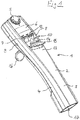
- the electronic manual dosing device 1 is an electronic hand dispenser. It has a bar-shaped housing 2 which is divided longitudinally into a front housing shell 3 and a rear housing shell 4.
- a dial 5 On the front of the housing 2 is located at the top of a dial 5 for selecting the respective operating mode.
- the dial 5 for example, the metering functions pipetting, dispensing and titration are adjustable.
- Including a display 6 is embedded in the front of the housing 2.
- rocker switch 7, 8 which serve to select various menu functions and setting parameters.
- the rocker switch 7, 8 are located on the left and right side of the housing electrical contacts 9, 10 for charging a battery of an electrical power supply 11.
- the battery is housed in the upper part of the housing 2.
- a trigger button 14 for triggering of suction and dispensing steps and for storing parameter settings.
- a throw-off button 15 which engages in the downwardly conforming to the flat front of the housing 2 bulge 13.
- the housing 2 has a first opening 17 through which a first receptacle 18 in the housing 2 for a syringe flange of a syringe barrel of a syringe is accessible from the outside.
- a first receptacle 18 in the housing 2 for a syringe flange of a syringe barrel of a syringe is accessible from the outside.
- a bell-shaped receiving body 19 located above the first receptacle 18 is a bell-shaped receiving body 19, in which a second receptacle 20 is arranged, which is accessible through a second opening 21 on the underside of the receiving body 19 for insertion of a piston rod end of a syringe plunger of the syringe.
- first receptacle 18 In the first receptacle 18 are first means for releasably holding the syringe flange to a stop 22 in the housing 2, which are designed as syringe gripping lever 23.
- the receiving body 19 has second means for releasable holding in the form of piston gripping levers 24, which serve to releasably hold the syringe plunger in the second receptacle 20.
- the attachment of syringe flange and syringe piston in the first and second receptacles 18, 20 by means of the first and second releasable holding means can be resolved by operating the Abwerfertaste 15 which acts via a gear 25 to the syringe gripping lever 23 and piston gripping lever 24.
- the syringe plunger is displaceable by means of a metering drive 26.
- the metering drive 26 comprises a spindle drive 27, which has a threaded spindle 28 and a spindle nut 29.
- the threaded spindle 28 has two longitudinally extending first flats 30.1, 30.2 on the two sides and in between two threaded portions 31.1, 31.2 of an external thread 31. According to Fig. 4 and 5 taper in cross section, the threaded portions 31.1, 31.2 in the radial direction to the outside.
- first flats 30.1, 30.2 are outward guide ribs 32.1, 32.2 before.
- Fig. 4 and 5 have the guide ribs 32.1, 32.2 at the outer end second flats 33.1, 33.2.
- they have guide portions 34.1, 34.2, 34.3, 34.4, whose distance from the central axis of the threaded spindle 28 corresponds to half the core diameter of an internal thread 35 of the spindle nut 29.
- Fig. 5 has the external thread 31 trapezoidal thread profiles 36.1, 36.2.
- the radially outer edges of the thread profiles 36.1, 36.2 are rounded.
- the transitions of the flanks 37.1, 37.2 of the thread profiles 36.1, 36.2 to the core of the threaded spindle 28 are rounded on both sides.
- the outer edges of the guide ribs 32.1, 32.2 and the transitions of the guide ribs 32.1, 32.2 to the first flats 30.1, 30.2 are rounded.
- the threaded spindle 28 is injection molded so that the parting plane of the two halves of the injection mold falls into the second flats 33.1, 33.2.
- the rounding of the guide ribs 32.1, 32.2 and the thread profiles 36.1, 36.2 are advantageous for the filling of the injection mold and the removal of the molding from the injection mold.
- the rounding of the profiles 36.1, 36.2 and the guide portions 34.1, 34.2, 34.3, 34.4 are also advantageous for the low-friction and low-wear adjustment of the threaded spindle 28 in the spindle nut 29th
- the spindle nut 29 has a central hollow shaft 38, on whose inner circumference the internal thread 35 is formed.
- the internal thread 35 extends continuously over a first portion of the sleeve.
- the thread profile of the internal thread 35 is also trapezoidal, with the radially inner ends of the profile are rounded and the transitions between the flanks of the profile also.
- a circular disk 39 which is formed as a toothed belt wheel 40 with a toothing 41 on the circumference.
- the hollow shaft 38 projects from the annular disc 39 on both sides.
- the external thread 31 of the threaded spindle 28 and the internal thread 35 of the spindle nut 29 are matched to one another, so that the threaded spindle 28 can be screwed into the spindle nut 29.
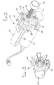
- the metering drive 26 according to Fig. 3 an electric drive motor 42 which carries a further toothed belt wheel 44 on a motor shaft 43.
- the spindle nut 29 is rotatably mounted on the hollow shaft 38 in two bearing bushes 45, which is held in two parallel holding plates 46 of a holder 47 at a defined distance from each other and from the drive motor 42.
- the holder 47 has bearing eyes 48 for fixing in the housing 2.
- a toothed belt 49 is placed around to transmit the rotation of the motor shaft 43 to the spindle nut 29.
- the metering drive 26 comprises pin-shaped first guide elements 50.1, 50.2, which protrude in opposite directions from the receiving body 19 to the outside.
- the first guide elements 50.1, 50.2 interact with guide tracks between strip-shaped second guide elements 51.1, 51.2 on the inner sides of the housing shells 3, 4.
- the threaded spindle 28 is prevented from rotating in the housing 2 and the receiving body 19 is guided in the axial direction of the threaded spindle 28.
- the dosing drive 26 includes an electrical control device 52 arranged in the upper region of the housing.
- the control device 52, the electric drive motor 42 and the remaining electronic components of the dosing device are fed by the electric power supply 11.
- the threaded spindle 28 and the spindle nut 29 are made of plastics and / or metal. Preferably, high performance plastics and / or engineering plastics are used for this purpose.
- the threaded spindle 28 and the spindle nut 29 are each made of PEEK.
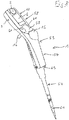
- the electronic manual dosing device 1 is an electronic handheld pipette. It has an upper housing part 53 in the form of a handle and a substantially cylindrical lower housing part 54.
- the upper housing part 53 contains a drive unit and the lower housing part 54 a displacement unit comprising a cylinder 55 and a piston 56 displaceable therein, which is displaceable by means of the drive unit.
- the upper housing part 53 has a substantially cylindrical body portion 57 and a box-shaped head portion 58, which forms an obtuse angle with the body portion 57.
- the head section has a dial 5 on the front side at the top for selecting the respective operating mode, for example pipetting, dispensing, pipetting and mixing, reverse pipetting, multiple recording, sequential dispensing.
- a display 6 is inserted into the front of the head portion 58.
- rocker button 59 for controlling the recording and dispensing of liquid and the setting of parameters available.
- keys 60 for selecting various menu functions and setting parameters.
- the Abwerfertaste 15 is with a Abwerferstange connected, which extends in the body portion 57 to the lower end thereof.
- the head portion 58 At the level of the display 6 are on the left and right side of the head portion 58 electrical contacts 9, 10 for charging a housed in the head portion 58 batteries of an electrical power supply 11.
- the battery is connected to a housed in the head portion 58 electrical control device 52.
- the electrical control device 52 is connected to the rocker switch 59 and the other buttons 60, a sensor for detecting the rotational position of the selector wheel 5 and a drive motor 42 of a metering drive 26.
- the body portion 57 has a cavity 62, in which the metering drive 26 is arranged at the top, which will be explained in more detail below.
- the body portion 57 has at the lower end a lower housing opening 63 through which the lower housing part 54 is inserted with its upper end in the cavity 62 of the body portion 57.
- the lower housing part 54 is releasably connected to the upper housing part 53 by means for releasably connecting the lower housing part 54 and the upper housing part 53.
- the means for releasably connecting comprise a latching connection with spring-loaded latching hook 64 of the lower housing part 54 which are latched in the cavity 62 behind locking edges of the upper housing part 53. The locking can be selectively canceled by moving a guided outside the lower housing part 54 Entrastungshülse 65.
- the lower housing part 54 has the cylinder 55 with the piston 56 displaceable longitudinally and sealingly guided therein.
- the cylinder 55 is formed as a bush ( liner ) which is held in a cylinder portion 66 of the housing base 54.
- the cylinder section is conical at the bottom Connecting portion 67 connected to a tube 68 having a sealing seat 69 at the lower end, on which the pipette tip 61 is clamped.
- the tube 68 defines a communication channel 70 which connects a first hole 71 at the lower end of the cylinder 55 to a second hole 72 in the sealing seat 69 at the lower end of the tube 68.
- the connecting portion 67 and the tube 68 is adapted to the outer shape thereof ejector sleeve 73 for pushing the pipette tip 61 from the sealing seat 69 is pushed.
- the ejector sleeve 73 is connected at the top via detachable coupling means of the ejector sleeve 73 and the ejector rod to the ejector rod.
- the releasable coupling means consist in a simple case in a clamping fit of the lower end of the Abwerferstange in a bore in a lateral projection on the upper edge of the ejector sleeve 73rd
- the lower housing part 54 carries at the top a closure cap 74 whose cap jacket 75 is connected to the cylinder section 66 and which has a central upper housing opening 77 in a cap bottom 76.
- the piston 56 is connected to a piston rod 78 which carries a plate 79 above. Between plate 79 and upper edge of the cylinder 55, a coil spring 80 is arranged, which presses the plate 79 in an initial position on the underside of the cap bottom 76.
- Fig. 9 to 12 engages the threaded spindle 28 of the metering drive 26 with its lower end through the upper housing opening 77 through into the cap 74 and is located at the top of the plate 79 at.
- FIGS. 12 and 13 corresponds to the metering 26 largely the metering 26 of Fig. 3 so the comments too Fig. 3 Accordingly, for the provided with the same reference numerals of FIGS. 12 and 13 be valid.
- Dosing drive 26 of FIGS. 12 and 13 contacted the lower end of the threaded spindle 28, the plate 79 and is not connected to a bell-shaped receiving body 19.
- the guide cylinder 81 On the inner circumference, the guide cylinder 81 has two guide grooves 82 which extend in the longitudinal direction of the guide cylinder 81.
- the two guide grooves 82 are diametrically opposite each other.
- FIGS. 10 and 13 carries the threaded spindle 28 at the upper end of a sleeve-shaped guide member 83 which has two outwardly projecting guide lugs 84 which engage in the guide grooves 82.
- the guide element 83 is firmly connected to the threaded spindle 28.
- the motor shaft 43 is rotated about the toothed belt 49, the spindle nut 29 is rotated and the threaded spindle 28 axially displaced.
- the piston 56 is inserted deeper into the cylinder 55 and displaced upward upon displacement of the threaded spindle 28, since the plate 79 is held by the prestressed coil spring 80 in contact with the lower end of the threaded spindle 28.
- an air column is displaced in the tube 68, which sucks liquid into the pipette tip 61 or expels it.
Landscapes
- Engineering & Computer Science (AREA)
- General Engineering & Computer Science (AREA)
- Health & Medical Sciences (AREA)
- Clinical Laboratory Science (AREA)
- Chemical & Material Sciences (AREA)
- Chemical Kinetics & Catalysis (AREA)
- Mechanical Engineering (AREA)
- Devices For Use In Laboratory Experiments (AREA)
- Injection Moulding Of Plastics Or The Like (AREA)
- Sampling And Sample Adjustment (AREA)
- Infusion, Injection, And Reservoir Apparatuses (AREA)
Priority Applications (5)
| Application Number | Priority Date | Filing Date | Title |
|---|---|---|---|
| PL17169764T PL3399214T3 (pl) | 2017-05-05 | 2017-05-05 | Elektroniczny napęd dozujący |
| EP17169764.2A EP3399214B1 (fr) | 2017-05-05 | 2017-05-05 | Entraînement de dosage électronique |
| JP2018088809A JP6821624B2 (ja) | 2017-05-05 | 2018-05-02 | 電子計量駆動装置 |
| CN201810417005.2A CN108786947B (zh) | 2017-05-05 | 2018-05-04 | 电子配量驱动装置 |
| US15/972,806 US10758899B2 (en) | 2017-05-05 | 2018-05-07 | Electronic dosing drive |
Applications Claiming Priority (1)
| Application Number | Priority Date | Filing Date | Title |
|---|---|---|---|
| EP17169764.2A EP3399214B1 (fr) | 2017-05-05 | 2017-05-05 | Entraînement de dosage électronique |
Publications (2)
| Publication Number | Publication Date |
|---|---|
| EP3399214A1 true EP3399214A1 (fr) | 2018-11-07 |
| EP3399214B1 EP3399214B1 (fr) | 2020-07-15 |
Family
ID=58692392
Family Applications (1)
| Application Number | Title | Priority Date | Filing Date |
|---|---|---|---|
| EP17169764.2A Active EP3399214B1 (fr) | 2017-05-05 | 2017-05-05 | Entraînement de dosage électronique |
Country Status (5)
| Country | Link |
|---|---|
| US (1) | US10758899B2 (fr) |
| EP (1) | EP3399214B1 (fr) |
| JP (1) | JP6821624B2 (fr) |
| CN (1) | CN108786947B (fr) |
| PL (1) | PL3399214T3 (fr) |
Cited By (2)
| Publication number | Priority date | Publication date | Assignee | Title |
|---|---|---|---|---|
| EP4616965A1 (fr) | 2024-03-13 | 2025-09-17 | JOST-Werke Deutschland GmbH | Système comprenant une cartouche et un dispositif d'actionnement |
| DE102024107124A1 (de) * | 2024-03-13 | 2025-09-18 | Jost-Werke Deutschland Gmbh | Vorrichtung zum Betätigen einer Kartusche |
Families Citing this family (9)
| Publication number | Priority date | Publication date | Assignee | Title |
|---|---|---|---|---|
| US10744498B2 (en) | 2017-09-19 | 2020-08-18 | Mettler-Toledo Rainin, LLC | Pipette quickset volume adjustment mechanism |
| US11446672B2 (en) | 2019-10-25 | 2022-09-20 | Mettler-Toledo Rainin, LLC | Powered positive displacement pipette syringe piston grasping mechanism |
| US11471878B2 (en) * | 2019-10-25 | 2022-10-18 | Mettler-Toledo Rainin, LLC | Powered positive displacement pipette |
| US11369954B2 (en) | 2019-10-25 | 2022-06-28 | Mettler-Toledo Rainin, LLC | Powered positive displacement pipette assembly |
| US11389792B2 (en) | 2019-10-25 | 2022-07-19 | Mettler-Toledo Rainin, LLC | Syringe for powered positive displacement pipette |
| EP4103327A1 (fr) | 2020-02-14 | 2022-12-21 | Denovix, Inc. | Pipette à plage volumétrique étendue dynamique |
| US12472491B2 (en) | 2022-06-28 | 2025-11-18 | Mettler-Toledo Rainin, LLC | Positive displacement pipette syringe with reduced fluid drag |
| US12544750B2 (en) | 2022-08-31 | 2026-02-10 | DeNovix Inc. | Multi-tiered pipette tip holder and ejection mechanism for a dynamic broad volumetric range pipette |
| DE102024127658A1 (de) * | 2024-09-24 | 2026-03-26 | Atlas Copco Ias Gmbh | Dosiervorrichtung zum Dosieren eines Fluids |
Citations (6)
| Publication number | Priority date | Publication date | Assignee | Title |
|---|---|---|---|---|
| DE1053883B (de) | 1957-06-03 | 1959-03-26 | Strobach Doerge & Co O H G | Gewindespindel |
| JPS6334361A (ja) * | 1986-07-25 | 1988-02-15 | Sansui Electric Co | ねじ送り装置 |
| US5620660A (en) | 1993-12-03 | 1997-04-15 | Eppendorf-Netheler-Hinz Gmbh | Pipette system |
| EP1449586B1 (fr) | 2003-02-20 | 2006-06-07 | Eppendorf Ag | Système de dosage avec mémoire et méthode pour l'utilisation |
| DE102015212448A1 (de) * | 2015-07-02 | 2017-01-05 | Zf Friedrichshafen Ag | Spindelantrieb und Aktuator mit einem Spindelantrieb |
| WO2017129179A1 (fr) * | 2016-01-29 | 2017-08-03 | HARTING Electronics GmbH | Élément de contact glissant à mouvement linéaire et à dispositif de transport et son procédé de fabrication |
Family Cites Families (23)
| Publication number | Priority date | Publication date | Assignee | Title |
|---|---|---|---|---|
| US4098125A (en) * | 1977-03-30 | 1978-07-04 | Lee Thomas E | Adjustable volume pipetting device |
| US4256153A (en) * | 1979-07-09 | 1981-03-17 | Societe Francaise Pour Le Developpement De L'automatisme En Biologie | Device for simultaneous transfer of a plurality of liquids |
| GB8713810D0 (en) * | 1987-06-12 | 1987-07-15 | Hypoguard Uk Ltd | Measured dose dispensing device |
| AU3156493A (en) * | 1991-11-29 | 1993-06-28 | Novo Nordisk A/S | A pen-shaped syringe |
| AU1860697A (en) * | 1995-09-08 | 1997-07-28 | Visionary Medical Products Corporation | Pen-type injector drive mechanism |
| US6299841B1 (en) * | 1999-03-05 | 2001-10-09 | Rainin Instrument Co., Inc. | Bilaterally symmetrical battery powered microprocessor controlled lightweight hand-holdable electronic pipette |
| US6899699B2 (en) * | 2001-01-05 | 2005-05-31 | Novo Nordisk A/S | Automatic injection device with reset feature |
| US6968749B2 (en) * | 2002-11-21 | 2005-11-29 | Arise Biotech Corporation | Portable automated pipette |
| JP3097201U (ja) * | 2003-03-31 | 2004-01-22 | 巫 東和 | 両方向螺旋式伝動軸の組み立て構造 |
| DE102004022419B4 (de) * | 2004-05-06 | 2007-01-25 | Eppendorf Ag | Pipette |
| JP2005337967A (ja) * | 2004-05-28 | 2005-12-08 | Juki Corp | 分注機 |
| JP4476906B2 (ja) * | 2005-09-02 | 2010-06-09 | 富士フイルム株式会社 | 分注装置 |
| GB0524604D0 (en) * | 2005-12-02 | 2006-01-11 | Owen Mumford Ltd | Injection method and apparatus |
| US20090071267A1 (en) * | 2007-09-17 | 2009-03-19 | Greg Mathus | Pipette tip ejection mechanism |
| CN201558707U (zh) * | 2009-07-21 | 2010-08-25 | 大龙医疗仪器有限公司 | 可调式移液器及其调整装置 |
| SE535983C2 (sv) * | 2010-04-20 | 2013-03-19 | Noviscens Ab | Spruta |
| US9295986B2 (en) * | 2012-05-02 | 2016-03-29 | Eppendorf Ag | Pipette with releasable locking of rotational position of actuating element |
| EP2854909B1 (fr) * | 2012-05-30 | 2020-07-15 | Sanofi-Aventis Deutschland GmbH | Palier pour un corps de tige de piston pour dispositif d'administration de médicament, tige de piston et corps de tige de piston |
| US20140010732A1 (en) * | 2012-06-18 | 2014-01-09 | Eppendorf Ag | Pipette for Operating a Syringe |
| US10525204B2 (en) * | 2013-11-22 | 2020-01-07 | Sanofi-Aventis Deutschland Gmbh | Drug delivery device |
| FI125449B (en) * | 2013-12-18 | 2015-10-15 | Thermo Fisher Scientific Oy | Electronic pipette |
| DE102014109345A1 (de) * | 2014-07-04 | 2016-01-07 | Eppendorf Ag | Pipette zum Betätigen einer Spritze |
| CN204620021U (zh) * | 2015-05-07 | 2015-09-09 | 湃思科技(苏州)有限公司 | 一种移液装置 |
-
2017
- 2017-05-05 EP EP17169764.2A patent/EP3399214B1/fr active Active
- 2017-05-05 PL PL17169764T patent/PL3399214T3/pl unknown
-
2018
- 2018-05-02 JP JP2018088809A patent/JP6821624B2/ja active Active
- 2018-05-04 CN CN201810417005.2A patent/CN108786947B/zh active Active
- 2018-05-07 US US15/972,806 patent/US10758899B2/en active Active
Patent Citations (8)
| Publication number | Priority date | Publication date | Assignee | Title |
|---|---|---|---|---|
| DE1053883B (de) | 1957-06-03 | 1959-03-26 | Strobach Doerge & Co O H G | Gewindespindel |
| JPS6334361A (ja) * | 1986-07-25 | 1988-02-15 | Sansui Electric Co | ねじ送り装置 |
| US5620660A (en) | 1993-12-03 | 1997-04-15 | Eppendorf-Netheler-Hinz Gmbh | Pipette system |
| EP0656229B1 (fr) | 1993-12-03 | 1997-07-16 | Eppendorf-Netheler-Hinz Gmbh | Système de pipette |
| EP1449586B1 (fr) | 2003-02-20 | 2006-06-07 | Eppendorf Ag | Système de dosage avec mémoire et méthode pour l'utilisation |
| US7402440B2 (en) | 2003-02-20 | 2008-07-22 | Eppendorf Ag | Proportioning system and process for operating a proportioning system |
| DE102015212448A1 (de) * | 2015-07-02 | 2017-01-05 | Zf Friedrichshafen Ag | Spindelantrieb und Aktuator mit einem Spindelantrieb |
| WO2017129179A1 (fr) * | 2016-01-29 | 2017-08-03 | HARTING Electronics GmbH | Élément de contact glissant à mouvement linéaire et à dispositif de transport et son procédé de fabrication |
Cited By (3)
| Publication number | Priority date | Publication date | Assignee | Title |
|---|---|---|---|---|
| EP4616965A1 (fr) | 2024-03-13 | 2025-09-17 | JOST-Werke Deutschland GmbH | Système comprenant une cartouche et un dispositif d'actionnement |
| EP4616964A1 (fr) | 2024-03-13 | 2025-09-17 | JOST-Werke Deutschland GmbH | Dispositif d'actionnement d'une cartouche |
| DE102024107124A1 (de) * | 2024-03-13 | 2025-09-18 | Jost-Werke Deutschland Gmbh | Vorrichtung zum Betätigen einer Kartusche |
Also Published As
| Publication number | Publication date |
|---|---|
| EP3399214B1 (fr) | 2020-07-15 |
| JP6821624B2 (ja) | 2021-01-27 |
| JP2018196881A (ja) | 2018-12-13 |
| US20180318825A1 (en) | 2018-11-08 |
| CN108786947B (zh) | 2021-10-29 |
| US10758899B2 (en) | 2020-09-01 |
| PL3399214T3 (pl) | 2021-01-25 |
| CN108786947A (zh) | 2018-11-13 |
Similar Documents
| Publication | Publication Date | Title |
|---|---|---|
| EP3399214B1 (fr) | Entraînement de dosage électronique | |
| EP3399215B1 (fr) | Entraînement de broche | |
| EP2165765B1 (fr) | Dispositif de pipetage avec filetage double | |
| EP3885046B1 (fr) | Dispositif de maintien des pointes de pipette et son utilisation | |
| EP2633915B1 (fr) | Pipette avec système de calibration | |
| EP1559480B1 (fr) | Pipette avec mécanisme de déplacement fixé de façon détachable au mécanisme d'actionnement | |
| EP3478418A1 (fr) | Tête de dosage, dispositif de dosage comprenant une tête de dosage et procédé de dosage au moyen d'une tête de dosage | |
| DE102004003433B4 (de) | Pipettiervorrichtung mit einer Abwurfeinrichtung für Pipettenspitzen | |
| EP3479129A1 (fr) | Tête de dosage, dispositif de dosage comprenant une tête de dosage et procédé de dosage au moyen d'une tête de dosage | |
| EP1875966A1 (fr) | Dispositif de pipetage | |
| EP3180139A1 (fr) | Outil multiple | |
| DE3520417C2 (de) | Vorrichtung zum lösbaren Befestigen eines scheibenförmigen Werkzeugs, vorzugsweise einer Schleifscheibe oder dgl., an der Arbeitsspindel eines kraftgetriebenen Handwerkzeugs | |
| EP4212306A1 (fr) | Dispositif d'accouplement et machine de traitement de matière plastique dotée d'un dispositif d'accouplement | |
| DE102022213778B3 (de) | Modulares Werkzeug und Verfahren zum Auswerfen eines Einsatzes eines modularen Werkzeugs | |
| DE102007042185A1 (de) | Elektrohandwerkzeuggerät | |
| EP4134166A1 (fr) | Pipette à utiliser avec une pointe de pipette | |
| DE102023131370B3 (de) | Mehrkanal-Unterteil für eine Fluidübertragungsvorrichtung sowie Fluidübertragungsvorrichtung | |
| DE102022113873B4 (de) | Pipettiervorrichtung | |
| EP4331725A1 (fr) | Tige de piston et procédé de fabrication d'une telle tige de piston | |
| EP4647230A1 (fr) | Dispositif d'engrenage, outil de façonnage et dispositif de façonnage | |
| WO2025008118A1 (fr) | Système doté d'un dispositif de vissage, d'un écrou et d'un élément de vissage présentant une zone filetée | |
| EP4206152A1 (fr) | Dispositif de changement d'outil pour un dispositif de formage de récipients en verre | |
| WO2025008129A1 (fr) | Système comprenant un dispositif de vissage, un écrou et un élément à visser comportant une région filetée | |
| DE102022005123A1 (de) | Modulares Werkzeug und Verfahren zum Auswerfen eines Einsatzes eines modularen Werkzeugs | |
| DE102024002691A1 (de) | Bearbeitungssystem |
Legal Events
| Date | Code | Title | Description |
|---|---|---|---|
| PUAI | Public reference made under article 153(3) epc to a published international application that has entered the european phase |
Free format text: ORIGINAL CODE: 0009012 |
|
| STAA | Information on the status of an ep patent application or granted ep patent |
Free format text: STATUS: THE APPLICATION HAS BEEN PUBLISHED |
|
| AK | Designated contracting states |
Kind code of ref document: A1 Designated state(s): AL AT BE BG CH CY CZ DE DK EE ES FI FR GB GR HR HU IE IS IT LI LT LU LV MC MK MT NL NO PL PT RO RS SE SI SK SM TR |
|
| AX | Request for extension of the european patent |
Extension state: BA ME |
|
| STAA | Information on the status of an ep patent application or granted ep patent |
Free format text: STATUS: REQUEST FOR EXAMINATION WAS MADE |
|
| 17P | Request for examination filed |
Effective date: 20190502 |
|
| RBV | Designated contracting states (corrected) |
Designated state(s): AL AT BE BG CH CY CZ DE DK EE ES FI FR GB GR HR HU IE IS IT LI LT LU LV MC MK MT NL NO PL PT RO RS SE SI SK SM TR |
|
| GRAP | Despatch of communication of intention to grant a patent |
Free format text: ORIGINAL CODE: EPIDOSNIGR1 |
|
| STAA | Information on the status of an ep patent application or granted ep patent |
Free format text: STATUS: GRANT OF PATENT IS INTENDED |
|
| RIC1 | Information provided on ipc code assigned before grant |
Ipc: B01L 3/02 20060101ALI20200115BHEP Ipc: F16H 25/24 20060101AFI20200115BHEP |
|
| INTG | Intention to grant announced |
Effective date: 20200218 |
|
| GRAS | Grant fee paid |
Free format text: ORIGINAL CODE: EPIDOSNIGR3 |
|
| GRAA | (expected) grant |
Free format text: ORIGINAL CODE: 0009210 |
|
| STAA | Information on the status of an ep patent application or granted ep patent |
Free format text: STATUS: THE PATENT HAS BEEN GRANTED |
|
| RIN1 | Information on inventor provided before grant (corrected) |
Inventor name: WILTH, MARC Inventor name: REICHMUTH, BURKHARDT Inventor name: SATTLER, JOERG |
|
| AK | Designated contracting states |
Kind code of ref document: B1 Designated state(s): AL AT BE BG CH CY CZ DE DK EE ES FI FR GB GR HR HU IE IS IT LI LT LU LV MC MK MT NL NO PL PT RO RS SE SI SK SM TR |
|
| REG | Reference to a national code |
Ref country code: CH Ref legal event code: EP Ref country code: GB Ref legal event code: FG4D Free format text: NOT ENGLISH |
|
| REG | Reference to a national code |
Ref country code: IE Ref legal event code: FG4D Free format text: LANGUAGE OF EP DOCUMENT: GERMAN |
|
| REG | Reference to a national code |
Ref country code: DE Ref legal event code: R096 Ref document number: 502017006165 Country of ref document: DE |
|
| REG | Reference to a national code |
Ref country code: AT Ref legal event code: REF Ref document number: 1291386 Country of ref document: AT Kind code of ref document: T Effective date: 20200815 |
|
| REG | Reference to a national code |
Ref country code: FI Ref legal event code: FGE |
|
| REG | Reference to a national code |
Ref country code: LT Ref legal event code: MG4D |
|
| REG | Reference to a national code |
Ref country code: CH Ref legal event code: NV Representative=s name: BOHEST AG, CH |
|
| REG | Reference to a national code |
Ref country code: NL Ref legal event code: MP Effective date: 20200715 |
|
| PG25 | Lapsed in a contracting state [announced via postgrant information from national office to epo] |
Ref country code: LT Free format text: LAPSE BECAUSE OF FAILURE TO SUBMIT A TRANSLATION OF THE DESCRIPTION OR TO PAY THE FEE WITHIN THE PRESCRIBED TIME-LIMIT Effective date: 20200715 Ref country code: HR Free format text: LAPSE BECAUSE OF FAILURE TO SUBMIT A TRANSLATION OF THE DESCRIPTION OR TO PAY THE FEE WITHIN THE PRESCRIBED TIME-LIMIT Effective date: 20200715 Ref country code: SE Free format text: LAPSE BECAUSE OF FAILURE TO SUBMIT A TRANSLATION OF THE DESCRIPTION OR TO PAY THE FEE WITHIN THE PRESCRIBED TIME-LIMIT Effective date: 20200715 Ref country code: NO Free format text: LAPSE BECAUSE OF FAILURE TO SUBMIT A TRANSLATION OF THE DESCRIPTION OR TO PAY THE FEE WITHIN THE PRESCRIBED TIME-LIMIT Effective date: 20201015 Ref country code: BG Free format text: LAPSE BECAUSE OF FAILURE TO SUBMIT A TRANSLATION OF THE DESCRIPTION OR TO PAY THE FEE WITHIN THE PRESCRIBED TIME-LIMIT Effective date: 20201015 Ref country code: GR Free format text: LAPSE BECAUSE OF FAILURE TO SUBMIT A TRANSLATION OF THE DESCRIPTION OR TO PAY THE FEE WITHIN THE PRESCRIBED TIME-LIMIT Effective date: 20201016 Ref country code: ES Free format text: LAPSE BECAUSE OF FAILURE TO SUBMIT A TRANSLATION OF THE DESCRIPTION OR TO PAY THE FEE WITHIN THE PRESCRIBED TIME-LIMIT Effective date: 20200715 Ref country code: PT Free format text: LAPSE BECAUSE OF FAILURE TO SUBMIT A TRANSLATION OF THE DESCRIPTION OR TO PAY THE FEE WITHIN THE PRESCRIBED TIME-LIMIT Effective date: 20201116 |
|
| PG25 | Lapsed in a contracting state [announced via postgrant information from national office to epo] |
Ref country code: RS Free format text: LAPSE BECAUSE OF FAILURE TO SUBMIT A TRANSLATION OF THE DESCRIPTION OR TO PAY THE FEE WITHIN THE PRESCRIBED TIME-LIMIT Effective date: 20200715 Ref country code: LV Free format text: LAPSE BECAUSE OF FAILURE TO SUBMIT A TRANSLATION OF THE DESCRIPTION OR TO PAY THE FEE WITHIN THE PRESCRIBED TIME-LIMIT Effective date: 20200715 Ref country code: IS Free format text: LAPSE BECAUSE OF FAILURE TO SUBMIT A TRANSLATION OF THE DESCRIPTION OR TO PAY THE FEE WITHIN THE PRESCRIBED TIME-LIMIT Effective date: 20201115 |
|
| PG25 | Lapsed in a contracting state [announced via postgrant information from national office to epo] |
Ref country code: NL Free format text: LAPSE BECAUSE OF FAILURE TO SUBMIT A TRANSLATION OF THE DESCRIPTION OR TO PAY THE FEE WITHIN THE PRESCRIBED TIME-LIMIT Effective date: 20200715 |
|
| REG | Reference to a national code |
Ref country code: DE Ref legal event code: R097 Ref document number: 502017006165 Country of ref document: DE |
|
| PG25 | Lapsed in a contracting state [announced via postgrant information from national office to epo] |
Ref country code: EE Free format text: LAPSE BECAUSE OF FAILURE TO SUBMIT A TRANSLATION OF THE DESCRIPTION OR TO PAY THE FEE WITHIN THE PRESCRIBED TIME-LIMIT Effective date: 20200715 Ref country code: IT Free format text: LAPSE BECAUSE OF FAILURE TO SUBMIT A TRANSLATION OF THE DESCRIPTION OR TO PAY THE FEE WITHIN THE PRESCRIBED TIME-LIMIT Effective date: 20200715 Ref country code: SM Free format text: LAPSE BECAUSE OF FAILURE TO SUBMIT A TRANSLATION OF THE DESCRIPTION OR TO PAY THE FEE WITHIN THE PRESCRIBED TIME-LIMIT Effective date: 20200715 Ref country code: RO Free format text: LAPSE BECAUSE OF FAILURE TO SUBMIT A TRANSLATION OF THE DESCRIPTION OR TO PAY THE FEE WITHIN THE PRESCRIBED TIME-LIMIT Effective date: 20200715 Ref country code: DK Free format text: LAPSE BECAUSE OF FAILURE TO SUBMIT A TRANSLATION OF THE DESCRIPTION OR TO PAY THE FEE WITHIN THE PRESCRIBED TIME-LIMIT Effective date: 20200715 Ref country code: CZ Free format text: LAPSE BECAUSE OF FAILURE TO SUBMIT A TRANSLATION OF THE DESCRIPTION OR TO PAY THE FEE WITHIN THE PRESCRIBED TIME-LIMIT Effective date: 20200715 |
|
| PLBE | No opposition filed within time limit |
Free format text: ORIGINAL CODE: 0009261 |
|
| STAA | Information on the status of an ep patent application or granted ep patent |
Free format text: STATUS: NO OPPOSITION FILED WITHIN TIME LIMIT |
|
| PG25 | Lapsed in a contracting state [announced via postgrant information from national office to epo] |
Ref country code: AL Free format text: LAPSE BECAUSE OF FAILURE TO SUBMIT A TRANSLATION OF THE DESCRIPTION OR TO PAY THE FEE WITHIN THE PRESCRIBED TIME-LIMIT Effective date: 20200715 |
|
| 26N | No opposition filed |
Effective date: 20210416 |
|
| PG25 | Lapsed in a contracting state [announced via postgrant information from national office to epo] |
Ref country code: SK Free format text: LAPSE BECAUSE OF FAILURE TO SUBMIT A TRANSLATION OF THE DESCRIPTION OR TO PAY THE FEE WITHIN THE PRESCRIBED TIME-LIMIT Effective date: 20200715 |
|
| PG25 | Lapsed in a contracting state [announced via postgrant information from national office to epo] |
Ref country code: SI Free format text: LAPSE BECAUSE OF FAILURE TO SUBMIT A TRANSLATION OF THE DESCRIPTION OR TO PAY THE FEE WITHIN THE PRESCRIBED TIME-LIMIT Effective date: 20200715 |
|
| PG25 | Lapsed in a contracting state [announced via postgrant information from national office to epo] |
Ref country code: LU Free format text: LAPSE BECAUSE OF NON-PAYMENT OF DUE FEES Effective date: 20210505 Ref country code: MC Free format text: LAPSE BECAUSE OF FAILURE TO SUBMIT A TRANSLATION OF THE DESCRIPTION OR TO PAY THE FEE WITHIN THE PRESCRIBED TIME-LIMIT Effective date: 20200715 |
|
| REG | Reference to a national code |
Ref country code: BE Ref legal event code: MM Effective date: 20210531 |
|
| PG25 | Lapsed in a contracting state [announced via postgrant information from national office to epo] |
Ref country code: IE Free format text: LAPSE BECAUSE OF NON-PAYMENT OF DUE FEES Effective date: 20210505 |
|
| PG25 | Lapsed in a contracting state [announced via postgrant information from national office to epo] |
Ref country code: BE Free format text: LAPSE BECAUSE OF NON-PAYMENT OF DUE FEES Effective date: 20210531 |
|
| REG | Reference to a national code |
Ref country code: DE Ref legal event code: R081 Ref document number: 502017006165 Country of ref document: DE Owner name: EPPENDORF SE, DE Free format text: FORMER OWNER: EPPENDORF AG, 22339 HAMBURG, DE |
|
| PG25 | Lapsed in a contracting state [announced via postgrant information from national office to epo] |
Ref country code: CY Free format text: LAPSE BECAUSE OF FAILURE TO SUBMIT A TRANSLATION OF THE DESCRIPTION OR TO PAY THE FEE WITHIN THE PRESCRIBED TIME-LIMIT Effective date: 20200715 |
|
| P01 | Opt-out of the competence of the unified patent court (upc) registered |
Effective date: 20230527 |
|
| REG | Reference to a national code |
Ref country code: AT Ref legal event code: MM01 Ref document number: 1291386 Country of ref document: AT Kind code of ref document: T Effective date: 20220505 |
|
| PG25 | Lapsed in a contracting state [announced via postgrant information from national office to epo] |
Ref country code: HU Free format text: LAPSE BECAUSE OF FAILURE TO SUBMIT A TRANSLATION OF THE DESCRIPTION OR TO PAY THE FEE WITHIN THE PRESCRIBED TIME-LIMIT; INVALID AB INITIO Effective date: 20170505 Ref country code: AT Free format text: LAPSE BECAUSE OF NON-PAYMENT OF DUE FEES Effective date: 20220505 |
|
| PG25 | Lapsed in a contracting state [announced via postgrant information from national office to epo] |
Ref country code: MK Free format text: LAPSE BECAUSE OF FAILURE TO SUBMIT A TRANSLATION OF THE DESCRIPTION OR TO PAY THE FEE WITHIN THE PRESCRIBED TIME-LIMIT Effective date: 20200715 |
|
| PG25 | Lapsed in a contracting state [announced via postgrant information from national office to epo] |
Ref country code: MT Free format text: LAPSE BECAUSE OF FAILURE TO SUBMIT A TRANSLATION OF THE DESCRIPTION OR TO PAY THE FEE WITHIN THE PRESCRIBED TIME-LIMIT Effective date: 20200715 |
|
| PGFP | Annual fee paid to national office [announced via postgrant information from national office to epo] |
Ref country code: FI Payment date: 20250526 Year of fee payment: 9 |
|
| PGFP | Annual fee paid to national office [announced via postgrant information from national office to epo] |
Ref country code: PL Payment date: 20250425 Year of fee payment: 9 Ref country code: DE Payment date: 20250521 Year of fee payment: 9 |
|
| PGFP | Annual fee paid to national office [announced via postgrant information from national office to epo] |
Ref country code: GB Payment date: 20250527 Year of fee payment: 9 |
|
| PGFP | Annual fee paid to national office [announced via postgrant information from national office to epo] |
Ref country code: FR Payment date: 20250528 Year of fee payment: 9 |
|
| PGFP | Annual fee paid to national office [announced via postgrant information from national office to epo] |
Ref country code: CH Payment date: 20250601 Year of fee payment: 9 |
|
| PG25 | Lapsed in a contracting state [announced via postgrant information from national office to epo] |
Ref country code: TR Free format text: LAPSE BECAUSE OF FAILURE TO SUBMIT A TRANSLATION OF THE DESCRIPTION OR TO PAY THE FEE WITHIN THE PRESCRIBED TIME-LIMIT Effective date: 20200715 |