EP3399233A1 - Procédé de fabrication d'un tube de transfert de chaleur comprenant une surface superhydrophobe - Google Patents
Procédé de fabrication d'un tube de transfert de chaleur comprenant une surface superhydrophobe Download PDFInfo
- Publication number
- EP3399233A1 EP3399233A1 EP18161729.1A EP18161729A EP3399233A1 EP 3399233 A1 EP3399233 A1 EP 3399233A1 EP 18161729 A EP18161729 A EP 18161729A EP 3399233 A1 EP3399233 A1 EP 3399233A1
- Authority
- EP
- European Patent Office
- Prior art keywords
- heat transfer
- transfer tube
- dipping
- nanostructures
- weight
- Prior art date
- Legal status (The legal status is an assumption and is not a legal conclusion. Google has not performed a legal analysis and makes no representation as to the accuracy of the status listed.)
- Granted
Links
Images


Classifications
-
- F—MECHANICAL ENGINEERING; LIGHTING; HEATING; WEAPONS; BLASTING
- F28—HEAT EXCHANGE IN GENERAL
- F28F—DETAILS OF HEAT-EXCHANGE AND HEAT-TRANSFER APPARATUS, OF GENERAL APPLICATION
- F28F13/00—Arrangements for modifying heat-transfer, e.g. increasing, decreasing
- F28F13/18—Arrangements for modifying heat-transfer, e.g. increasing, decreasing by applying coatings, e.g. radiation-absorbing, radiation-reflecting; by surface treatment, e.g. polishing
- F28F13/185—Heat-exchange surfaces provided with microstructures or with porous coatings
- F28F13/187—Heat-exchange surfaces provided with microstructures or with porous coatings especially adapted for evaporator surfaces or condenser surfaces, e.g. with nucleation sites
-
- F—MECHANICAL ENGINEERING; LIGHTING; HEATING; WEAPONS; BLASTING
- F28—HEAT EXCHANGE IN GENERAL
- F28F—DETAILS OF HEAT-EXCHANGE AND HEAT-TRANSFER APPARATUS, OF GENERAL APPLICATION
- F28F19/00—Preventing the formation of deposits or corrosion, e.g. by using filters or scrapers
- F28F19/02—Preventing the formation of deposits or corrosion, e.g. by using filters or scrapers by using coatings, e.g. vitreous or enamel coatings
- F28F19/06—Preventing the formation of deposits or corrosion, e.g. by using filters or scrapers by using coatings, e.g. vitreous or enamel coatings of metal
-
- B—PERFORMING OPERATIONS; TRANSPORTING
- B05—SPRAYING OR ATOMISING IN GENERAL; APPLYING FLUENT MATERIALS TO SURFACES, IN GENERAL
- B05D—PROCESSES FOR APPLYING FLUENT MATERIALS TO SURFACES, IN GENERAL
- B05D5/00—Processes for applying liquids or other fluent materials to surfaces to obtain special surface effects, finishes or structures
- B05D5/08—Processes for applying liquids or other fluent materials to surfaces to obtain special surface effects, finishes or structures to obtain an anti-friction or anti-adhesive surface
- B05D5/083—Processes for applying liquids or other fluent materials to surfaces to obtain special surface effects, finishes or structures to obtain an anti-friction or anti-adhesive surface involving the use of fluoropolymers
-
- B—PERFORMING OPERATIONS; TRANSPORTING
- B05—SPRAYING OR ATOMISING IN GENERAL; APPLYING FLUENT MATERIALS TO SURFACES, IN GENERAL
- B05D—PROCESSES FOR APPLYING FLUENT MATERIALS TO SURFACES, IN GENERAL
- B05D7/00—Processes, other than flocking, specially adapted for applying liquids or other fluent materials to particular surfaces or for applying particular liquids or other fluent materials
- B05D7/14—Processes, other than flocking, specially adapted for applying liquids or other fluent materials to particular surfaces or for applying particular liquids or other fluent materials to metal, e.g. car bodies
- B05D7/146—Processes, other than flocking, specially adapted for applying liquids or other fluent materials to particular surfaces or for applying particular liquids or other fluent materials to metal, e.g. car bodies to metallic pipes or tubes
-
- C—CHEMISTRY; METALLURGY
- C09—DYES; PAINTS; POLISHES; NATURAL RESINS; ADHESIVES; COMPOSITIONS NOT OTHERWISE PROVIDED FOR; APPLICATIONS OF MATERIALS NOT OTHERWISE PROVIDED FOR
- C09D—COATING COMPOSITIONS, e.g. PAINTS, VARNISHES OR LACQUERS; FILLING PASTES; CHEMICAL PAINT OR INK REMOVERS; INKS; CORRECTING FLUIDS; WOODSTAINS; PASTES OR SOLIDS FOR COLOURING OR PRINTING; USE OF MATERIALS THEREFOR
- C09D5/00—Coating compositions, e.g. paints, varnishes or lacquers, characterised by their physical nature or the effects produced; Filling pastes
- C09D5/16—Antifouling paints; Underwater paints
- C09D5/1656—Antifouling paints; Underwater paints characterised by the film-forming substance
- C09D5/1662—Synthetic film-forming substance
- C09D5/1675—Polyorganosiloxane-containing compositions
-
- C—CHEMISTRY; METALLURGY
- C23—COATING METALLIC MATERIAL; COATING MATERIAL WITH METALLIC MATERIAL; CHEMICAL SURFACE TREATMENT; DIFFUSION TREATMENT OF METALLIC MATERIAL; COATING BY VACUUM EVAPORATION, BY SPUTTERING, BY ION IMPLANTATION OR BY CHEMICAL VAPOUR DEPOSITION, IN GENERAL; INHIBITING CORROSION OF METALLIC MATERIAL OR INCRUSTATION IN GENERAL
- C23C—COATING METALLIC MATERIAL; COATING MATERIAL WITH METALLIC MATERIAL; SURFACE TREATMENT OF METALLIC MATERIAL BY DIFFUSION INTO THE SURFACE, BY CHEMICAL CONVERSION OR SUBSTITUTION; COATING BY VACUUM EVAPORATION, BY SPUTTERING, BY ION IMPLANTATION OR BY CHEMICAL VAPOUR DEPOSITION, IN GENERAL
- C23C22/00—Chemical surface treatment of metallic material by reaction of the surface with a reactive liquid, leaving reaction products of surface material in the coating, e.g. conversion coatings, passivation of metals
- C23C22/05—Chemical surface treatment of metallic material by reaction of the surface with a reactive liquid, leaving reaction products of surface material in the coating, e.g. conversion coatings, passivation of metals using aqueous solutions
-
- F—MECHANICAL ENGINEERING; LIGHTING; HEATING; WEAPONS; BLASTING
- F22—STEAM GENERATION
- F22B—METHODS OF STEAM GENERATION; STEAM BOILERS
- F22B37/00—Component parts or details of steam boilers
- F22B37/02—Component parts or details of steam boilers applicable to more than one kind or type of steam boiler
- F22B37/10—Water tubes; Accessories therefor
- F22B37/107—Protection of water tubes
-
- F—MECHANICAL ENGINEERING; LIGHTING; HEATING; WEAPONS; BLASTING
- F28—HEAT EXCHANGE IN GENERAL
- F28F—DETAILS OF HEAT-EXCHANGE AND HEAT-TRANSFER APPARATUS, OF GENERAL APPLICATION
- F28F19/00—Preventing the formation of deposits or corrosion, e.g. by using filters or scrapers
- F28F19/02—Preventing the formation of deposits or corrosion, e.g. by using filters or scrapers by using coatings, e.g. vitreous or enamel coatings
- F28F19/04—Preventing the formation of deposits or corrosion, e.g. by using filters or scrapers by using coatings, e.g. vitreous or enamel coatings of rubber; of plastics material; of varnish
-
- B—PERFORMING OPERATIONS; TRANSPORTING
- B05—SPRAYING OR ATOMISING IN GENERAL; APPLYING FLUENT MATERIALS TO SURFACES, IN GENERAL
- B05D—PROCESSES FOR APPLYING FLUENT MATERIALS TO SURFACES, IN GENERAL
- B05D1/00—Processes for applying liquids or other fluent materials
- B05D1/18—Processes for applying liquids or other fluent materials performed by dipping
-
- B—PERFORMING OPERATIONS; TRANSPORTING
- B05—SPRAYING OR ATOMISING IN GENERAL; APPLYING FLUENT MATERIALS TO SURFACES, IN GENERAL
- B05D—PROCESSES FOR APPLYING FLUENT MATERIALS TO SURFACES, IN GENERAL
- B05D2202/00—Metallic substrate
-
- B—PERFORMING OPERATIONS; TRANSPORTING
- B05—SPRAYING OR ATOMISING IN GENERAL; APPLYING FLUENT MATERIALS TO SURFACES, IN GENERAL
- B05D—PROCESSES FOR APPLYING FLUENT MATERIALS TO SURFACES, IN GENERAL
- B05D2254/00—Tubes
- B05D2254/02—Applying the material on the exterior of the tube
-
- B—PERFORMING OPERATIONS; TRANSPORTING
- B05—SPRAYING OR ATOMISING IN GENERAL; APPLYING FLUENT MATERIALS TO SURFACES, IN GENERAL
- B05D—PROCESSES FOR APPLYING FLUENT MATERIALS TO SURFACES, IN GENERAL
- B05D2506/00—Halogenated polymers
-
- B—PERFORMING OPERATIONS; TRANSPORTING
- B05—SPRAYING OR ATOMISING IN GENERAL; APPLYING FLUENT MATERIALS TO SURFACES, IN GENERAL
- B05D—PROCESSES FOR APPLYING FLUENT MATERIALS TO SURFACES, IN GENERAL
- B05D2518/00—Other type of polymers
- B05D2518/10—Silicon-containing polymers
- B05D2518/12—Ceramic precursors (polysiloxanes, polysilazanes)
-
- F—MECHANICAL ENGINEERING; LIGHTING; HEATING; WEAPONS; BLASTING
- F28—HEAT EXCHANGE IN GENERAL
- F28B—STEAM OR VAPOUR CONDENSERS
- F28B1/00—Condensers in which the steam or vapour is separate from the cooling medium by walls, e.g. surface condenser
- F28B1/02—Condensers in which the steam or vapour is separate from the cooling medium by walls, e.g. surface condenser using water or other liquid as the cooling medium
-
- F—MECHANICAL ENGINEERING; LIGHTING; HEATING; WEAPONS; BLASTING
- F28—HEAT EXCHANGE IN GENERAL
- F28D—HEAT-EXCHANGE APPARATUS, NOT PROVIDED FOR IN ANOTHER SUBCLASS, IN WHICH THE HEAT-EXCHANGE MEDIA DO NOT COME INTO DIRECT CONTACT
- F28D21/00—Heat-exchange apparatus not covered by any of the groups F28D1/00 - F28D20/00
- F28D2021/0019—Other heat exchangers for particular applications; Heat exchange systems not otherwise provided for
- F28D2021/0061—Other heat exchangers for particular applications; Heat exchange systems not otherwise provided for for phase-change applications
- F28D2021/0063—Condensers
-
- F—MECHANICAL ENGINEERING; LIGHTING; HEATING; WEAPONS; BLASTING
- F28—HEAT EXCHANGE IN GENERAL
- F28F—DETAILS OF HEAT-EXCHANGE AND HEAT-TRANSFER APPARATUS, OF GENERAL APPLICATION
- F28F2245/00—Coatings; Surface treatments
- F28F2245/04—Coatings; Surface treatments hydrophobic
-
- F—MECHANICAL ENGINEERING; LIGHTING; HEATING; WEAPONS; BLASTING
- F28—HEAT EXCHANGE IN GENERAL
- F28F—DETAILS OF HEAT-EXCHANGE AND HEAT-TRANSFER APPARATUS, OF GENERAL APPLICATION
- F28F2255/00—Heat exchanger elements made of materials having special features or resulting from particular manufacturing processes
- F28F2255/20—Heat exchanger elements made of materials having special features or resulting from particular manufacturing processes with nanostructures
Definitions
- the present disclosure relates to a method for manufacturing a heat transfer tube comprising a superhydrophobic surface, and in particular, to the heat transfer tube comprising the superhydrophobic surface by forming nanostructures on a surface of the heat transfer tube or further forming a hydrophobic coating layer.
- thermoelectric power plants heat is generated with uranium, petroleum or coal as a fuel, and steam is formed by heating water circulating the system using this heat.
- the formed steam produces electricity by operating a turbine, and the steam passing through the turbine is cooled in a condenser and changed again into water.
- a water cooling method of cooling the condensation process using water in a steam circulating power generation methods requires large quantities of cooling water, and seawater is used as the cooling water used in the condenser. Accordingly, the plants are generally built near the coast in order to smoothly supply and discharge the seawater used as the cooling water.
- the condenser is also expressed as a steam condenser, and by continuously flowing seawater in a condenser heat transfer tube, a temperature of the inner wall of the condenser is continuously lowered. Then, water vapor coming out through the valve and operated by the turbine is run right against the inner wall of the condenser, and at the moment, the water vapor becomes a condensate, and the condensate is sent back to a boiler pipe to become water of approximately 500 degrees Celsius and pass the turbine through the valve.
- the condenser has a problem of causing corrosion due to condensation outside the heat transfer tubes, when the corrosion is generated by a condensed fluid remaining on the surface.
- the corrosion formed due to condensation outside the tube or a condensed fluid remaining on the surface may also occur during a heat exchange between flow paths through a heat transfer plate.
- a crosslinked hydrophobic film is utilized, where the crosslinked hydrophobic film contains a resin comprising a fluorine atom-containing group, a quaternary ammonium salt group-containing modified epoxy resin and an amino resin.
- the hydrophobic film has problems in that it becomes difficult to form a superhydrophobic film having a contact angle of 150 degrees or larger between the surface and the water drop and to maintain hydrophobic coating under a high temperature environment.
- a coating solution has been applied using a roll coater method or the like. Because the condenser has the plurality of heat transfer tubes assembled, each of the heat transfer tubes needs to be coated and assembled in order to form a hydrophobic coating layer.
- the individual coating of the plurality of heat transfer tubes may be inconvenient, and the hydrophobic coating layer may come off during the assembly of the coated heat transfer tubes.
- the present disclosure relates to a heat transfer tube comprising a superhydrophobic surface, and a method for manufacturing the same.
- the present disclosure is directed to providing a heat transfer tube capable of comprising a superhydrophobic surface under a high temperature environment as well by forming nanostructures on a surface of the heat transfer tube.
- the present disclosure is also directed to providing a manufacturing method of forming nanostructures by dipping a plurality of assembled heat transfer tubes and forming a hydrophobic coating layer, and capable of preventing damages that may occur during the process of forming nanostructures on the surface of the heat transfer tube and assembling the heat transfer tube thereafter.
- the present disclosure is also directed to providing a heat transfer tube comprising enhanced hydrophobicity by further forming a hydrophobic coating layer on a heat transfer tube with nanostructures formed on the surface.
- Embodiments of the present disclosure are provided in order to more fully describe the present disclosure to those comprising common knowledge in the art.
- the following embodiments may be modified to various different forms, and the scope of the present disclosure is not limited to the following embodiments. These embodiments are provided in order to make the present disclosure fuller and more complete, and to completely transfer ideas of the present disclosure to those skilled in the art.
- a heat transfer tube of the present disclosure means, like a flow path of a heat exchanger, a heat transfer tube that may be comprised in condensation related equipment in fields such as power plants, freshwater technologies and water harvesting as well as a heat transfer tube forming a condenser.
- the present disclosure relates to a method for manufacturing a heat transfer tube comprising a superhydrophobic surface, the method preferably comprising 1) ultrasonicating a heat transfer tube using an organic solvent; 2) washing the ultrasonicated heat transfer tube of 1); 3) removing a metal oxide on a surface of the heat transfer tube by dipping the washed heat transfer tube of 2) into an acidic solution; 4) preparing a dipping solution for forming nanostructures; and 5) dipping the metal oxide-removed heat transfer tube of 3) with the metal oxide removed into the dipping solution for forming nanostructures of 4).
- the dipping solution for forming nanostructures of the present disclosure may comprise water; NaClO 2 ; NaOH; and Na 3 PO 4 .
- the dipping solution for forming nanostructures of the present disclosure may comprise the NaClO 2 in 1 parts by weight to 4 parts by weight; the NaOH in 3.5 parts by weight to 10 parts by weight; and the Na 3 PO 4 in 5 parts by weight to 11 parts by weight with respect to 100 parts by weight of the water.
- 5) of the present disclosure may dip the heat transfer tube into the dipping solution for forming nanostructures for 10 minutes or longer.
- the organic solvent of 1) of the present disclosure may be selected from the group consisting of acetone, ethanol and mixtures thereof.
- the heat transfer tube is placed in acetone and first ultrasonicated for 3 minutes to 7 minutes and then the heat transfer tube is placed in ethanol and second ultrasonicated for 3 minutes to 7 minutes.
- the washing the ultrasonicated heat transfer tube comprises washing the ultrasonicated heat transfer tube with water, and removing residual moisture using nitrogen gas.
- the acidic solution of 3) of the present disclosure may be 2 M hydrochloric acid (HC1).
- the heat transfer tube of the present disclosure may be formed with Al-bras.
- the heat transfer tube of the present disclosure may have a form of assembling a plurality of heat transfer tubes.
- 6) forming a hydrophobic coating layer by dipping the heat transfer tube into a silane-based coating solution may be further comprised after 5) of the present disclosure.
- the silane-based coating solution of the present disclosure may comprise a silane-based compound selected from the group including, or consisting of, heptadeca-fluoro-1,1,2,2,2-tetrahydrodecyl trichlorosilane (HDFS), trichloro(1H,1H,2H,2H-perfluorooctyl)silane (TFTS), trichloro(octyl)silane (OTS) and dichlorodimethylsilane (DCDMS).
- a silane-based compound selected from the group including, or consisting of, heptadeca-fluoro-1,1,2,2,2-tetrahydrodecyl trichlorosilane (HDFS), trichloro(1H,1H,2H,2H-perfluorooctyl)silane (TFTS), trichloro(octyl)silane (OTS) and dichlorodi
- the silane-based coating solution further comprises a volatile solvent.
- the volatile solvent is hexane (C 6 H 14 ).
- the silane-based coating solution of the present disclosure may comprise a silane-based compound selected from the group including, or consisting of, heptadeca-fluoro-1,1,2,2,2-tetrahydrodecyl trichlorosilane (HDFS), trichloro(1H,1H,2H,2H-perfluorooctyl)silane (TFTS), trichloro(octyl)silane (OTS) and dichlorodimethylsilane (DCDMS), and a volatile solvent.
- a silane-based compound selected from the group including, or consisting of, heptadeca-fluoro-1,1,2,2,2-tetrahydrodecyl trichlorosilane (HDFS), trichloro(1H,1H,2H,2H-perfluorooctyl)silane (TFTS), trichloro(octyl)silane (OTS)
- the silane-based coating solution of the present disclosure may comprise the silane-based compound in 0.1 parts by weight or greater based on 100 parts by weight of the volatile solvent.
- the nanostructures of the present disclosure may comprise Cu 2 O and CuO.
- the present disclosure relates to a heat transfer tube comprising a superhydrophobic surface comprising nanostructures formed on the surface using the above-mentioned manufacturing method.
- the nanostructures of the present disclosure may comprise Cu 2 O and CuO.
- the heat transfer tube of the present disclosure may comprise a silane-based compound.
- the heat transfer tube of the present disclosure may have a surface contact angle of 145 degrees or larger.
- a heat transfer tube comprising a superhydrophobic surface of the present disclosure and a method for manufacturing the same will be described with reference to drawings as follows.
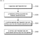
- FIG. 1 is a flow chart illustrating a method for manufacturing a heat transfer tube comprising a superhydrophobic surface according to one embodiment of the present disclosure. More specifically, the method comprises 1) washing a heat transfer tube (S100); 2) preparing a dipping solution for forming nanostructures (S200); and 3) dipping the washed heat transfer tube into the dipping solution for forming nanostructures (S300).
- the heat transfer tube in the present disclosure may be formed with Al-bras, and as the heat transfer tube for forming nanostructures, each heat transfer tube may be individually formed nanostructures, and may be assembled to be used in a condenser. However, in order to simplify a production process, a plurality of heat transfer tubes are assembled in a form to be used in the condenser, and nanostructures may be formed on the surfaces of the assembled heat transfer tubes using the above-mentioned manufacturing method.
- FIG. 12 shows pictures comparing a condensation behavior of a heat transfer formed with Al-bras and a condensation behavior of a heat transfer tube formed with Al-bras and comprising a superhydrophobic surface according to one embodiment of the present disclosure.
- the heat transfer tube formed with Al-bras is without a hydrophobic surface, and thus water vapor comprised in the air that is in contact with the heat transfer tube is not readily condensed whereas, in the heat transfer tube according to one embodiment of the present disclosure, condensation on the surface of the heat transfer tube is identified to have the superhydrophobic surface.
- step 1) a heat transfer tube is washed, and more specifically, the step comprises 1-1) ultrasonicating a heat transfer tube in an organic solvent; 1-2) washing the ultrasonicated heat transfer tube using water, and then removing residual moisture using nitrogen gas; and 1-3) dipping the moisture-removed heat transfer tube into an acidic solution, washing the tube with water, and then removing residual moisture using nitrogen gas.
- the organic solvent may be selected from the group consisting of acetone, ethanol and mixtures thereof. More specifically, the heat transfer tube is placed in acetone and first ultrasonicated for 3 minutes to 7 minutes, and the heat transfer tube completed with the first ultrasonication may be placed in ethanol and second ultrasonicated for 3 minutes to 7 minutes.
- the organic solvent is used as a quenching liquid, and foreign substances and the like adhering to the surface may be removed by placing the heat transfer tube in the quenching liquid and applying ultrasonic vibration to the quenching liquid.
- the heat transfer tube is washed using water, and after removing residual moisture using nitrogen gas, the moisture-removed heat transfer tube is dipped into an acidic solution.
- the heat transfer tube is formed with metals and comprises a naturally occurring metal oxide layer, and in order to remove such an oxide layer naturally formed on the surface of the metal heat transfer tube, the heat transfer tube may be dipped into an acidic solution.
- the acidic solution may use a 2 M hydrochloric acid (HCl) solution, but, in addition to the hydrochloric acid solution, any solution may be used without any limit as long as it is capable of removing the oxide layer produced on the heat transfer tube surface.
- dipping the heat transfer tube into the acidic solution is for removing the metal oxide layer produced on the surface, and the metal oxide layer may be removed by dipping the tube for a short period of time, such as 20 to 40 seconds.
- the metal oxide may remain without being removed, and when dipped for longer than 40 seconds, metals of the heat transfer tube other than the metal oxide layer may be removed.
- Step 2) comprises preparing a dipping solution for forming nanostructures, and the dipping solution for forming nanostructures comprises water; NaClO 2 ; NaOH; and Na 3 PO 4 . More specifically, the dipping solution may comprise NaClO 2 in 1 part by weight to 4 parts by weight; NaOH in 3.5 parts by weight to 10 parts by weight; and Na 3 PO 4 in 5 parts by weight to 11 parts by weight with respect to 100 parts by weight of water, although the dipping solution is not limited to the example.
- NaClO 2 of the dipping solution for forming the nanostructures is for providing oxygen atoms, and being comprised of it in less than 1 part by weight or greater than 4 parts by weight may have a problem in that the nanostructures may not be formed on the heat transfer tube.
- NaOH is a strong oxidizer and is a main material forming the nanostructures on the heat transfer tube surface, and being comprised of it in less than 4 parts by weight may hinder the formation of the nanostructures.
- Na 3 PO 4 is a material comprising a CuO layer formed on a Cu 2 O layer and facilitating adhesion between the two layers.
- FIG. 3 is a SEM image of the heat transfer tube comprising nanostructures formed on the surface
- FIG. 4 is a FIB image of the heat transfer tube comprising nanostructures formed on the surface.
- formation of the Cu 2 O layer and the CuO layer is identified on the heat transfer tube surface.
- nanostructures formed on the surface of the heat transfer tube are the Cu 2 O layer and the CuO layer
- Na 3 PO 4 allows the CuO layer to form on an upper surface of the Cu 2 O layer formed adjoining the surface of the heat transfer tube, where Na 3 PO 4 may facilitate adhesion of the two layers.
- Step 3) comprises dipping the washed heat transfer tube into the dipping solution for forming nanostructures, and the dipping may be for 10 minutes or longer.
- the nanostructure formation found on the heat transfer tube surface may be non-uniform.
- the nanostructures may be uniformly formed on the heat transfer tube surface.
- FIG. 2 is a flow chart illustrating a method for manufacturing a heat transfer tube comprising a superhydrophobic surface according to one embodiment of the present disclosure. More specifically, the method may comprise 1) washing a heat transfer tube (S100); 2) preparing a dipping solution for forming nanostructures (S200); 3) dipping the washed heat transfer tube into the dipping solution for forming nanostructures (S300); and 4) dipping the heat transfer tube into a silane-based coating solution for coating (S400).
- S100 heat transfer tube
- S200 preparing a dipping solution for forming nanostructures
- S300 dipping the washed heat transfer tube into the dipping solution for forming nanostructures
- S400 silane-based coating solution for coating
- nanostructures are formed on a surface of the heat transfer tube, and in step 4) (S400), a hydrophobic coating layer may be further comprised on an upper surface of the nanostructures formed on the surface of the heat transfer tube.
- a hydrophobic coating layer may be formed by dipping the nanostructure-formed heat transfer tube into the silane-based coating solution. By exhibiting superhydrophobicity, the hydrophobic coating layer may enhance hydrophobicity of the nanostructure-formed heat transfer tube.
- the coating layer may be formed by dipping the heat transfer tube comprising nanostructures formed on the surface into the silane-based coating solution.
- the silane-based coating solution may comprise a silane-based compound selected from the group consisting of heptadeca-fluoro-1,1,2,2,2-tetrahydrodecyl trichlorosilane (HDFS), trichloro(1H,1H,2H,2H-perfluorooctyl)silane (TFTS), trichloro(octyl)silane (OTS) and dichlorodimethylsilane (DCDMS).
- HDFS heptadeca-fluoro-1,1,2,2,2-tetrahydrodecyl trichlorosilane
- TFTS trichloro(1H,1H,2H,2H-perfluorooctyl)silane
- OTS trichloro(octyl)silane
- the coating solution formed only with the silane-based compound may be used, but, a coating solution prepared by mixing a volatile solvent to the silane-based compound may be used as well.
- a coating solution prepared by mixing a volatile solvent to the silane-based compound may be used as well.
- the silane-based compound in 0.1 part by weight or greater is mixed with 100 parts by weight of the volatile solvent. If the silane-based compound in less than 0.1 part by weight, the hydrophobic coating layer may not be uniformly coated on the heat transfer tube surface, but when the silane-based compound of 0.1 part by weight or greater is present, a uniform hydrophobic coating layer may be formed on the heat transfer tube surface.
- the volatile solvent is hexane (C 6 H 14 ), but, any volatile solvents known to those skilled in the art may be used without being limited to the example.
- a prepared heat transfer tube is placed in acetone (CH 3 COCH 3 ) and ultrasonicated for 3 minutes to 7 minutes, and after that, placed in ethanol (C 2 H 5 OH) and ultrasonicated for 3 minutes to 7 minutes. After the ultrasonication, the tube is washed with DI water, and moisture remaining on the surface is removed using nitrogen gas.
- the tube is dipped into a 2 M hydrochloric acid (HCl) solution for 20 seconds to 40 seconds. After dipped into the hydrochloric acid, the tube is washed using DI water, and moisture remaining on the surface is removed using nitrogen gas.
- HCl hydrochloric acid
- a dipping solution for forming nanostructures is prepared by mixing NaClO 2 in 3.75 parts by weight, NaOH in 5 parts by weight and Na 3 PO 4 in 10 parts by weight with 100 parts by weight of DI water, and the dipping solution for forming nanostructures is boiled. After dipping the washed heat transfer tube into the boiled dipping solution for forming nanostructures, the tube is washed using DI water, and moisture remaining on the surface is removed using nitrogen gas.
- Preparation is carried out in the same manner as in Preparation Example 1 except that NaClO 2 of the dipping solution for forming nanostructures is introduced in 1.5 parts by weight.
- Preparation is carried out in the same manner as in Preparation Example 1 except that NaOH of the dipping solution for forming nanostructures is introduced in 4 parts by weight.
- Preparation is carried out in the same manner as in Preparation Example 1 except that Na 3 PO 4 of the dipping solution for forming nanostructures is introduced in 6 parts by weight.
- Preparation is carried out in the same manner as in Preparation Example 1 except that the heat transfer tube is dipped into the dipping solution for forming nanostructures for 20 minutes.
- hydrophobic coating 0.1 part by weight of heptadeca-fluoro-1,1,2,2,2-tetrahydrodecyl trichlorosilane (HDFS) based on 100 mL of a hexane (C 6 H 14 ) solution is mixed to prepare a hydrophobic coating solution.
- HDFS heptadeca-fluoro-1,1,2,2,2-tetrahydrodecyl trichlorosilane
- the nanostructure-formed heat transfer tube of Preparation Example 1 is dipped into the hydrophobic coating solution for 90 seconds, and washed using DI water, and moisture remaining on the surface is removed using nitrogen gas. After that, the tube is dried in a 50°C oven for the preparation.
- Preparation is carried out in the same manner as in Preparation Example 6 except that a hydrophobic coating solution of 100% by weight of heptadeca-fluoro-1,1,2,2,2-tetrahydrodecyl trichlorosilane (HDFS) is used.
- a hydrophobic coating solution of 100% by weight of heptadeca-fluoro-1,1,2,2,2-tetrahydrodecyl trichlorosilane (HDFS) is used.
- Preparation is carried out in the same manner as in Preparation Example 6 except that the heat transfer tube is dipped into the hydrophobic coating solution for 120 seconds.
- Preparation is carried out in the same manner as in Preparation Example 1 except that NaClO 2 of the dipping solution for forming nanostructures is introduced in 0.75 part by weight.
- Preparation is carried out in the same manner as in Preparation Example 1 except that NaClO 2 of the dipping solution for forming nanostructures is introduced in 4.5 parts by weight.
- Preparation is carried out in the same manner as in Preparation Example 1 except that NaOH of the dipping solution for forming nanostructures is introduced in 3 parts by weight.
- Preparation is carried out in the same manner as in Preparation Example 1 except that Na 3 PO 4 of the dipping solution for forming nanostructures is introduced in 4 parts by weight.
- Preparation is carried out in the same manner as in Preparation Example 1 except that Na 3 PO 4 of the dipping solution for forming nanostructures is introduced in 12 parts by weight.
- Preparation is carried out in the same manner as in Preparation Example 1 except that the heat transfer tube is dipped into the dipping solution for forming nanostructures for 5 minutes.
- Preparation is carried out in the same manner as in Preparation Example 6 except that HDFS is introduced in 0.05 part by weight with respect to 100 parts by weight of hexane as the hydrophobic coating solution.
- Preparation is carried out in the same manner as in Preparation Example 6 except that the heat transfer tube is dipped into the hydrophobic coating solution for just 60 seconds.
- the nanostructures are formed with CuO and Cu 2 O and thereby comprise Cu and O the most.
- Al, Zn and Cu are components forming Al-bras.
- C corresponds to impurities due to contamination naturally occurring during an EDS measuring process after producing the nanostructures on the surface of the heat transfer tube.
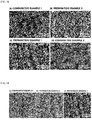
- FIG. 5 shows SEM images for the heat transfer tubes of Preparation Example 1, Preparation Example 2, Comparative Example 1 and Comparative Example 2.
- Comparative Examples 1 and 2 of the figure parts comprising no nanostructure formation are partly found, but nanostructures are uniformly formed in Preparation Examples 1 and 2 of the figure.
- FIG. 6 shows SEM images for the heat transfer tubes of Preparation Example 1, Preparation Example 3 and Comparative Example 3.
- Comparative Example 3 parts comprising no nanostructure formation are partly found, but nanostructures are uniformly formed in Preparation Examples 1 and 3.
- FIG. 7 shows SEM images for the heat transfer tubes of Preparation Example 1, Preparation Example 4, Comparative Example 4 and Comparative Example 5.
- Comparative Examples 4 and 5 parts comprising no nanostructure formation are partly found, but the nanostructures are uniformly formed in Preparation Examples 1 and 4.
- the nanostructures are not uniformly formed on the surface of the heat transfer tube, thus causing a problem of reduced hydrophobicity.
- Preparation Examples 1 and 4 comprising the Na 3 PO 4 range in the range of the present disclosure, uniform nanostructure formation is identified, and the heat transfer tube comprising a superhydrophobic surface is identified.
- FIG. 8 shows SEM images for the heat transfer tubes of Preparation Example 1, Preparation Example 5 and Comparative Example 6.
- Comparative Example 6 which illustrates dipping into the dipping solution for forming nanostructures for approximately 5 minutes, parts comprising no nanostructure formation are found, but the nanostructures are uniformly formed in Preparation Examples 1 and 5, which illustrate dipping into the dipping solution for 10 minutes or longer.
- the nanostructures are not uniformly formed on the surface of the heat transfer tube when dipping for shorter than 10 minutes, thus causing a problem of reduced hydrophobicity.
- Preparation Examples 1 and 5 which have a dipping time of 10 minutes or longer, uniform nanostructure formation is identified, and the heat transfer tube comprising a superhydrophobic surface is identified.
- a hydrophobic coating solution is prepared while varying a silane-based compound content in the hydrophobic coating solution as in Preparation Example 6, Preparation Example 7 and Comparative Example 5, and after forming a hydrophobic coating layer by dipping the nanostructure-formed heat transfer tube thereinto, a contact angle is measured.
- FIG. 9 measures an advancing contact angle, a stationary contact angle and a receding contact angle for Preparation Example 6, Preparation Example 7 and Comparative Example 7.
- Comparative Example 5 which comprises a silane-based compound in 0.05 part by weight in the hydrophobic coating solution, a receding contact angle is measured as approximately 104 degrees Celsius, which means that the coating layer is non-uniformly formed, and in Preparation Examples 6 and 7, superhydrophobicity is obtained in light of the fact that all the contact angles appeared to be 145 degrees or larger.
- a hydrophobic coating layer is formed while varying a time of dipping the heat transfer tube into the hydrophobic coating solution as in Preparation Example 6, Preparation Example 8 and Comparative Example 8, and a contact angle is measured.
- FIG. 10 shows results of measuring contact angles of the heat transfer tubes comprising a hydrophobic coating layer formed by Preparation Example 6, Preparation Example 8 and Comparative Example 8.
- a stationary contact angle and a receding contact angle are measured as approximately 130 degrees, which means that the hydrophobic coating layer is non-uniformly formed, and the hydrophobic coating layer being non-uniformly formed as in Comparative Example 6 has a problem of reducing hydrophobicity.
- the hydrophobic coating layer is uniformly formed with all the contact angles being 145 degrees or larger, and the heat transfer tube surface exhibiting superhydrophobicity.
- the condensation heat transfer test is measured using condensation heat transfer test equipment as in FIG. 11 .
- a square vacuum chamber made of stainless steel is present, and a heat transfer tube is connected internally.
- non-condensable gas inhibiting condensation needs to be removed, and inside the chamber is conditioned to be 0.5 Pa or less using a vacuum pump.
- the corresponding degree of vacuum is identified through a pressure sensor connected to the left side of the vacuum chamber.
- Using a separate stainless circular container connected to the right side of the vacuum chamber hot steam is supplied into the vacuum chamber in which an environment of 0.5 Pa or less of the degree of vacuum is created. Clean water is introduced to the corresponding stainless circular container, and steam as above is supplied by boiling the water to 100 degrees using a heater.
- thermocouple probes are connected to the inlet/outlet parts of the heat transfer tube to measure changes in the temperature when the water supplied from the thermal bath passed through the heat transfer tube.
- a condensation behavior at the outer wall of the heat transfer tube is observed using a CCD camera located on the left side of the vacuum chamber, and the temperature values measured from the thermocouple probes are received using a computer to finally measure a condensation heat transfer coefficient.
- a condensation heat transfer coefficient is calculated as follows. First, temperatures of the heat transfer tube inlet/outlet are measured using thermocouple probes, and a total energy amount supplied to the heat transfer tube is calculated using these values.
- Q m ⁇ C P T end ⁇ T in
- Q means a total heat transfer amount
- ⁇ means a flow rate of water flowing inside the heat transfer tube
- C p means specific heat under constant pressure of water
- T end means a temperature of water on the outlet side of the heat transfer tube
- T in means a temperature of water on the inlet side of the heat transfer tube.
- T LMTD T 2 ⁇ T in ⁇ T 1 ⁇ T end ln T 1 ⁇ T in T 2 ⁇ T end
- the overall heat transfer coefficient calculated as above is different from a condensation heat transfer coefficient.
- the overall heat transfer coefficient is a heat transfer coefficient value between water flowing inside the heat transfer tube and external steam.
- h i k i d ID f / 8 Re ⁇ 1000 Pr 1 + 12.7 f / 8 1 / 2 Pr 2 / 4 ⁇ 1
- f is a friction coefficient of the tube
- Re is a Reynolds number of water flowing inside the heat transfer tube
- Pr is a Prandtl number.
- the heat transfer tube comprising nanostructures and a hydrophobic coating layer formed on the surface by Preparation Example 6 has an improvement in the condensation heat transfer performance by approximately 4.1 times compared to the heat transfer tube formed with Al-bras without surface modification.
- liquid film-type condensation takes place on the Al-bras surface without surface modification, whereas liquid drops are readily removed from the surface as water drop condensation occurs on the Al-bras surface comprising nanostructures and hydrophobic coating formed on the surface as in Preparation Example 6 of the present disclosure.
- Such a water drop condensation behavior is more superior in the condensation heat transfer performance compared to a film condensation behavior.
- FIG. 13 shows results of measuring a heat transfer coefficient (supersaturation level, S), which means condensation heat transfer performance, of the Al-bras surface without surface modification and the Al-bras surface of Preparation Example 6 at various condensation levels, and it is identified that the Al-bras of Preparation Example 6 has a larger condensation heat transfer coefficient (h c ) by approximately 3 times.
- S supersaturation level
- the present disclosure relates to a heat transfer tube comprising nanostructures formed on the surface, and a method for manufacturing the same, and by forming the nanostructures on a heat transfer tube surface, a superhydrophobic surface can be obtained under a high temperature environment as well.
- superhydrophobicity may be enhanced by further forming a hydrophobic coating layer on the nanostructure-formed heat transfer tube surface.
Landscapes
- Engineering & Computer Science (AREA)
- Chemical & Material Sciences (AREA)
- Mechanical Engineering (AREA)
- Thermal Sciences (AREA)
- General Engineering & Computer Science (AREA)
- Physics & Mathematics (AREA)
- Wood Science & Technology (AREA)
- Materials Engineering (AREA)
- Life Sciences & Earth Sciences (AREA)
- Organic Chemistry (AREA)
- Crystallography & Structural Chemistry (AREA)
- General Chemical & Material Sciences (AREA)
- Chemical Kinetics & Catalysis (AREA)
- Metallurgy (AREA)
- Other Surface Treatments For Metallic Materials (AREA)
- Application Of Or Painting With Fluid Materials (AREA)
- Materials Applied To Surfaces To Minimize Adherence Of Mist Or Water (AREA)
Applications Claiming Priority (1)
| Application Number | Priority Date | Filing Date | Title |
|---|---|---|---|
| KR1020170032240A KR101953966B1 (ko) | 2017-03-15 | 2017-03-15 | 초발수 표면이 구현된 전열관 및 이의 제조 방법 |
Publications (2)
| Publication Number | Publication Date |
|---|---|
| EP3399233A1 true EP3399233A1 (fr) | 2018-11-07 |
| EP3399233B1 EP3399233B1 (fr) | 2022-04-06 |
Family
ID=61655650
Family Applications (1)
| Application Number | Title | Priority Date | Filing Date |
|---|---|---|---|
| EP18161729.1A Active EP3399233B1 (fr) | 2017-03-15 | 2018-03-14 | Procédé de fabrication d'un tube de transfert de chaleur comprenant une surface superhydrophobe |
Country Status (4)
| Country | Link |
|---|---|
| US (1) | US10663237B2 (fr) |
| EP (1) | EP3399233B1 (fr) |
| JP (1) | JP6708680B2 (fr) |
| KR (1) | KR101953966B1 (fr) |
Cited By (1)
| Publication number | Priority date | Publication date | Assignee | Title |
|---|---|---|---|---|
| AU2019392204B2 (en) * | 2018-12-03 | 2025-12-18 | Exaeris Water Innovations, Llc | Atmospheric water generator apparatus |
Families Citing this family (3)
| Publication number | Priority date | Publication date | Assignee | Title |
|---|---|---|---|---|
| CN111609558B (zh) * | 2020-05-15 | 2022-01-07 | 华帝股份有限公司 | 一种防止水管腐蚀的方法及应用其的热水器 |
| CN113522284B (zh) * | 2021-07-15 | 2023-05-16 | 山东科技大学 | 一种处理抗生素废液的复合材料及其制备方法和应用 |
| CN114593630B (zh) * | 2022-03-29 | 2023-12-22 | 郑州轻工业大学 | 一种纳米磁性粒子亲疏水智能管及其控制系统 |
Citations (6)
| Publication number | Priority date | Publication date | Assignee | Title |
|---|---|---|---|---|
| EP0226861A1 (fr) * | 1985-11-27 | 1987-07-01 | Mitsubishi Materials Corporation | Matériau échangeur de chaleur et son procédé de fabrication |
| WO2004113456A2 (fr) * | 2003-06-23 | 2004-12-29 | University Of Zurich | Enduit superhydrophobe |
| DE102008064125A1 (de) * | 2008-12-19 | 2010-06-24 | Siemens Aktiengesellschaft | Kondensatorrohr mit erhöhter Hydrophobie, Herstellungsverfahren und Verwendung dazu |
| EP2476990A2 (fr) * | 2011-01-13 | 2012-07-18 | Samsung Electronics Co., Ltd. | Couche de revêtement de surface et échangeur thermique incluant la couche de revêtement de surface |
| US20140182790A1 (en) * | 2011-07-21 | 2014-07-03 | Postech Academy-Industry Foundation | Method for processing a super-hydrophobic surface, and evaporator having the super-hydrophobic surface |
| US20170010060A1 (en) * | 2015-07-06 | 2017-01-12 | Chih-Hung Chang | Heterogeneous surfaces for patterned bubble arrays, enhanced heat transfer, & advanced heat exhanger applications |
Family Cites Families (24)
| Publication number | Priority date | Publication date | Assignee | Title |
|---|---|---|---|---|
| JPH06265292A (ja) * | 1993-03-15 | 1994-09-20 | Hitachi Ltd | 海水を取扱う熱交換器の防食薬品供給装置 |
| JPH1096599A (ja) * | 1996-05-10 | 1998-04-14 | Hitachi Ltd | 室外用熱交換器ユニットおよびこれを用いた空気調和機 |
| JPH1191024A (ja) * | 1997-09-19 | 1999-04-06 | Hitachi Ltd | 撥水性部材及びその製造方法 |
| JP2000154986A (ja) * | 1998-11-18 | 2000-06-06 | Sigma:Kk | 復水器のリーク探知方法およびその装置 |
| JP4175449B2 (ja) * | 2000-04-25 | 2008-11-05 | 三菱重工業株式会社 | 多管式熱交換器及びその組立方法 |
| AU2002360005A1 (en) * | 2002-10-10 | 2004-05-04 | Iseya Manufacturing Co. | Method for heat conduction and system for heat exchange between solid and fluid |
| JP2005098694A (ja) * | 2002-10-10 | 2005-04-14 | Sukeaki Kunugi | 固体と流体との間の熱交換システム |
| JP2004294049A (ja) * | 2002-11-26 | 2004-10-21 | Daikin Ind Ltd | 対空気用熱交換器及び冷凍装置 |
| KR100534616B1 (ko) * | 2004-05-03 | 2005-12-07 | 삼성전자주식회사 | 잉크젯 헤드용 노즐 플레이트의 발수처리 방법 |
| JP2006132840A (ja) * | 2004-11-05 | 2006-05-25 | Mitsubishi Electric Corp | 熱交換器 |
| JP4974332B2 (ja) * | 2005-09-07 | 2012-07-11 | 一般財団法人電力中央研究所 | ナノ構造体およびその製造方法 |
| EP2260123A1 (fr) * | 2008-02-28 | 2010-12-15 | Corning Incorporated | Procédés électrochimiques de fabrication de nanostructures |
| JP5205229B2 (ja) * | 2008-11-27 | 2013-06-05 | 株式会社神戸製鋼所 | 多管式熱交換器の管取付け方法、及び、多管式熱交換器の管取付け装置 |
| KR101206150B1 (ko) * | 2010-10-11 | 2012-11-28 | (주) 동명기계 | 탄소나노튜브를 이용한 고효율 전열관, 그 제조방법 및 그 이용방법 |
| JP2012228670A (ja) * | 2011-04-27 | 2012-11-22 | Denso Corp | 撥水性基材、撥水性基材を用いた熱交換器、および撥水性基材の製造方法 |
| JP5600081B2 (ja) | 2011-05-10 | 2014-10-01 | 日本軽金属株式会社 | 熱交換器用プレコートフィン材及び熱交換器 |
| JP2013120047A (ja) * | 2011-12-09 | 2013-06-17 | Panasonic Corp | 冷蔵庫 |
| JP2013180221A (ja) * | 2012-02-29 | 2013-09-12 | Mitsubishi Electric Corp | 撥水性被膜の形成方法、撥水性部材及び熱交換器 |
| US12202229B2 (en) * | 2012-03-02 | 2025-01-21 | Massachusetts Institute Of Technology | Superhydrophobic nanostructures |
| BR112015011378A8 (pt) * | 2012-11-19 | 2019-10-01 | Massachusetts Inst Technology | artigo compreendendo uma superfície impregnada com líquido e método de uso do referido artigo |
| JP6356702B2 (ja) * | 2013-02-15 | 2018-07-11 | マサチューセッツ インスティテュート オブ テクノロジー | 滴状凝縮のためのグラフトポリマー表面、ならびに関連使用および製造方法 |
| KR101628117B1 (ko) * | 2014-06-24 | 2016-06-08 | 군산대학교산학협력단 | 보행 패턴 분석 시스템 및 방법 |
| KR101617611B1 (ko) * | 2014-06-27 | 2016-05-03 | 국민대학교산학협력단 | 초친수성 금속 표면 형성방법 |
| KR101479448B1 (ko) * | 2014-07-02 | 2015-01-06 | 한양대학교 산학협력단 | 산화세륨 초발수 나노/마이크로 구조체를 포함하는 열교환기 및 이의 제조방법 |
-
2017
- 2017-03-15 KR KR1020170032240A patent/KR101953966B1/ko active Active
-
2018
- 2018-03-08 JP JP2018042378A patent/JP6708680B2/ja active Active
- 2018-03-14 US US15/921,618 patent/US10663237B2/en active Active
- 2018-03-14 EP EP18161729.1A patent/EP3399233B1/fr active Active
Patent Citations (6)
| Publication number | Priority date | Publication date | Assignee | Title |
|---|---|---|---|---|
| EP0226861A1 (fr) * | 1985-11-27 | 1987-07-01 | Mitsubishi Materials Corporation | Matériau échangeur de chaleur et son procédé de fabrication |
| WO2004113456A2 (fr) * | 2003-06-23 | 2004-12-29 | University Of Zurich | Enduit superhydrophobe |
| DE102008064125A1 (de) * | 2008-12-19 | 2010-06-24 | Siemens Aktiengesellschaft | Kondensatorrohr mit erhöhter Hydrophobie, Herstellungsverfahren und Verwendung dazu |
| EP2476990A2 (fr) * | 2011-01-13 | 2012-07-18 | Samsung Electronics Co., Ltd. | Couche de revêtement de surface et échangeur thermique incluant la couche de revêtement de surface |
| US20140182790A1 (en) * | 2011-07-21 | 2014-07-03 | Postech Academy-Industry Foundation | Method for processing a super-hydrophobic surface, and evaporator having the super-hydrophobic surface |
| US20170010060A1 (en) * | 2015-07-06 | 2017-01-12 | Chih-Hung Chang | Heterogeneous surfaces for patterned bubble arrays, enhanced heat transfer, & advanced heat exhanger applications |
Cited By (1)
| Publication number | Priority date | Publication date | Assignee | Title |
|---|---|---|---|---|
| AU2019392204B2 (en) * | 2018-12-03 | 2025-12-18 | Exaeris Water Innovations, Llc | Atmospheric water generator apparatus |
Also Published As
| Publication number | Publication date |
|---|---|
| JP6708680B2 (ja) | 2020-06-10 |
| JP2018155483A (ja) | 2018-10-04 |
| US10663237B2 (en) | 2020-05-26 |
| US20180266776A1 (en) | 2018-09-20 |
| KR20180105330A (ko) | 2018-09-28 |
| EP3399233B1 (fr) | 2022-04-06 |
| KR101953966B1 (ko) | 2019-03-04 |
Similar Documents
| Publication | Publication Date | Title |
|---|---|---|
| EP3399233B1 (fr) | Procédé de fabrication d'un tube de transfert de chaleur comprenant une surface superhydrophobe | |
| Del Col et al. | Film condensation of steam flowing on a hydrophobic surface | |
| Chilton et al. | Heat transfer coefficients in agitated vessels | |
| Bisetto et al. | Experimental analysis of steam condensation over conventional and superhydrophilic vertical surfaces | |
| Parin et al. | Heat transfer and droplet population during dropwise condensation on durable coatings | |
| Kananeh et al. | Experimental study of dropwise condensation on plasma-ion implanted stainless steel tubes | |
| Caruso et al. | Film condensation in inclined tubes with noncondensable gases: an experimental study on the local heat transfer coefficient | |
| Park et al. | Heat transfer augmentation in two-phase flow heat exchanger using porous microstructures and a hydrophobic coating | |
| Parin et al. | Heat transfer during dropwise condensation of steam over a mirror polished sol-gel coated aluminum substrate | |
| Kim et al. | Dropwise condensation induced on chromium ion implanted aluminum surface | |
| Kim et al. | Steam condensate behavior and heat transfer performance on chromium-ion-implanted metal surfaces | |
| Zhou et al. | Experimental study of condensation heat transfer characteristics on metal foam wrapped tubes under sloshing conditions | |
| Abraham et al. | Experimental studies on thermal spray-coated horizontal tubes for falling film evaporation in multi-effect desalination system | |
| Budakli et al. | Effect of polymer coating on vapor condensation heat transfer | |
| Dehghani et al. | Impact of relative humidity, temperature difference, and surface type on humid air condensation heat transfer | |
| EP3959295B1 (fr) | Composante de transfert de chaleur et de masse comprenant une surface traiter avec un lubrifiant | |
| Tancon et al. | Dropwise-to-filmwise transition during condensation of steam on hydrophilic surfaces | |
| Zhu et al. | Effects of high fractional noncondensable gas on condensation in the dewvaporation desalination process | |
| Panuthara et al. | Experimental investigation of condensation heat transfer on chlorotriethylsilane coated grooved vertical tube | |
| Davar et al. | Effects of superhydrophobic, hydrophobic and hybrid surfaces in condensation heat transfer | |
| Kumar et al. | Condensation of R-134a vapor over single horizontal circular integral-fin tubes with trapezoidal fins | |
| CN109975046B (zh) | 一种用于测试降膜蒸发器预热和蒸发传热性能的方法 | |
| Tatara et al. | Measurement of spray boiling refrigerant coefficients in an integral-fin tube bundle segment simulating a full bundle | |
| CN210015067U (zh) | 一种降膜蒸发器传热性能测试系统 | |
| Kuroda et al. | Development of aluminum-water heat pipes |
Legal Events
| Date | Code | Title | Description |
|---|---|---|---|
| PUAI | Public reference made under article 153(3) epc to a published international application that has entered the european phase |
Free format text: ORIGINAL CODE: 0009012 |
|
| STAA | Information on the status of an ep patent application or granted ep patent |
Free format text: STATUS: REQUEST FOR EXAMINATION WAS MADE |
|
| 17P | Request for examination filed |
Effective date: 20180314 |
|
| AK | Designated contracting states |
Kind code of ref document: A1 Designated state(s): AL AT BE BG CH CY CZ DE DK EE ES FI FR GB GR HR HU IE IS IT LI LT LU LV MC MK MT NL NO PL PT RO RS SE SI SK SM TR |
|
| AX | Request for extension of the european patent |
Extension state: BA ME |
|
| RBV | Designated contracting states (corrected) |
Designated state(s): AL AT BE BG CH CY CZ DE DK EE ES FI FR GB GR HR HU IE IS IT LI LT LU LV MC MK MT NL NO PL PT RO RS SE SI SK SM TR |
|
| REG | Reference to a national code |
Ref country code: DE Ref legal event code: R079 Ref document number: 602018033220 Country of ref document: DE Free format text: PREVIOUS MAIN CLASS: F22B0037100000 Ipc: B05D0005080000 |
|
| GRAP | Despatch of communication of intention to grant a patent |
Free format text: ORIGINAL CODE: EPIDOSNIGR1 |
|
| STAA | Information on the status of an ep patent application or granted ep patent |
Free format text: STATUS: GRANT OF PATENT IS INTENDED |
|
| GRAJ | Information related to disapproval of communication of intention to grant by the applicant or resumption of examination proceedings by the epo deleted |
Free format text: ORIGINAL CODE: EPIDOSDIGR1 |
|
| RIC1 | Information provided on ipc code assigned before grant |
Ipc: B05D 1/18 20060101ALI20210910BHEP Ipc: F28F 13/18 20060101ALI20210910BHEP Ipc: F22B 37/10 20060101ALI20210910BHEP Ipc: F28D 21/00 20060101ALI20210910BHEP Ipc: F28B 1/02 20060101ALI20210910BHEP Ipc: C23C 22/05 20060101ALI20210910BHEP Ipc: B05D 7/14 20060101ALI20210910BHEP Ipc: B05D 5/08 20060101AFI20210910BHEP |
|
| GRAP | Despatch of communication of intention to grant a patent |
Free format text: ORIGINAL CODE: EPIDOSNIGR1 |
|
| INTG | Intention to grant announced |
Effective date: 20211013 |
|
| INTG | Intention to grant announced |
Effective date: 20211027 |
|
| GRAS | Grant fee paid |
Free format text: ORIGINAL CODE: EPIDOSNIGR3 |
|
| GRAA | (expected) grant |
Free format text: ORIGINAL CODE: 0009210 |
|
| STAA | Information on the status of an ep patent application or granted ep patent |
Free format text: STATUS: THE PATENT HAS BEEN GRANTED |
|
| AK | Designated contracting states |
Kind code of ref document: B1 Designated state(s): AL AT BE BG CH CY CZ DE DK EE ES FI FR GB GR HR HU IE IS IT LI LT LU LV MC MK MT NL NO PL PT RO RS SE SI SK SM TR |
|
| REG | Reference to a national code |
Ref country code: GB Ref legal event code: FG4D |
|
| REG | Reference to a national code |
Ref country code: CH Ref legal event code: EP |
|
| REG | Reference to a national code |
Ref country code: AT Ref legal event code: REF Ref document number: 1480812 Country of ref document: AT Kind code of ref document: T Effective date: 20220415 |
|
| REG | Reference to a national code |
Ref country code: DE Ref legal event code: R096 Ref document number: 602018033220 Country of ref document: DE |
|
| REG | Reference to a national code |
Ref country code: IE Ref legal event code: FG4D |
|
| REG | Reference to a national code |
Ref country code: LT Ref legal event code: MG9D |
|
| REG | Reference to a national code |
Ref country code: NL Ref legal event code: MP Effective date: 20220406 |
|
| REG | Reference to a national code |
Ref country code: AT Ref legal event code: MK05 Ref document number: 1480812 Country of ref document: AT Kind code of ref document: T Effective date: 20220406 |
|
| PG25 | Lapsed in a contracting state [announced via postgrant information from national office to epo] |
Ref country code: NL Free format text: LAPSE BECAUSE OF FAILURE TO SUBMIT A TRANSLATION OF THE DESCRIPTION OR TO PAY THE FEE WITHIN THE PRESCRIBED TIME-LIMIT Effective date: 20220406 |
|
| PG25 | Lapsed in a contracting state [announced via postgrant information from national office to epo] |
Ref country code: SE Free format text: LAPSE BECAUSE OF FAILURE TO SUBMIT A TRANSLATION OF THE DESCRIPTION OR TO PAY THE FEE WITHIN THE PRESCRIBED TIME-LIMIT Effective date: 20220406 Ref country code: PT Free format text: LAPSE BECAUSE OF FAILURE TO SUBMIT A TRANSLATION OF THE DESCRIPTION OR TO PAY THE FEE WITHIN THE PRESCRIBED TIME-LIMIT Effective date: 20220808 Ref country code: NO Free format text: LAPSE BECAUSE OF FAILURE TO SUBMIT A TRANSLATION OF THE DESCRIPTION OR TO PAY THE FEE WITHIN THE PRESCRIBED TIME-LIMIT Effective date: 20220706 Ref country code: LT Free format text: LAPSE BECAUSE OF FAILURE TO SUBMIT A TRANSLATION OF THE DESCRIPTION OR TO PAY THE FEE WITHIN THE PRESCRIBED TIME-LIMIT Effective date: 20220406 Ref country code: HR Free format text: LAPSE BECAUSE OF FAILURE TO SUBMIT A TRANSLATION OF THE DESCRIPTION OR TO PAY THE FEE WITHIN THE PRESCRIBED TIME-LIMIT Effective date: 20220406 Ref country code: GR Free format text: LAPSE BECAUSE OF FAILURE TO SUBMIT A TRANSLATION OF THE DESCRIPTION OR TO PAY THE FEE WITHIN THE PRESCRIBED TIME-LIMIT Effective date: 20220707 Ref country code: FI Free format text: LAPSE BECAUSE OF FAILURE TO SUBMIT A TRANSLATION OF THE DESCRIPTION OR TO PAY THE FEE WITHIN THE PRESCRIBED TIME-LIMIT Effective date: 20220406 Ref country code: ES Free format text: LAPSE BECAUSE OF FAILURE TO SUBMIT A TRANSLATION OF THE DESCRIPTION OR TO PAY THE FEE WITHIN THE PRESCRIBED TIME-LIMIT Effective date: 20220406 Ref country code: BG Free format text: LAPSE BECAUSE OF FAILURE TO SUBMIT A TRANSLATION OF THE DESCRIPTION OR TO PAY THE FEE WITHIN THE PRESCRIBED TIME-LIMIT Effective date: 20220706 Ref country code: AT Free format text: LAPSE BECAUSE OF FAILURE TO SUBMIT A TRANSLATION OF THE DESCRIPTION OR TO PAY THE FEE WITHIN THE PRESCRIBED TIME-LIMIT Effective date: 20220406 |
|
| PG25 | Lapsed in a contracting state [announced via postgrant information from national office to epo] |
Ref country code: RS Free format text: LAPSE BECAUSE OF FAILURE TO SUBMIT A TRANSLATION OF THE DESCRIPTION OR TO PAY THE FEE WITHIN THE PRESCRIBED TIME-LIMIT Effective date: 20220406 Ref country code: PL Free format text: LAPSE BECAUSE OF FAILURE TO SUBMIT A TRANSLATION OF THE DESCRIPTION OR TO PAY THE FEE WITHIN THE PRESCRIBED TIME-LIMIT Effective date: 20220406 Ref country code: LV Free format text: LAPSE BECAUSE OF FAILURE TO SUBMIT A TRANSLATION OF THE DESCRIPTION OR TO PAY THE FEE WITHIN THE PRESCRIBED TIME-LIMIT Effective date: 20220406 Ref country code: IS Free format text: LAPSE BECAUSE OF FAILURE TO SUBMIT A TRANSLATION OF THE DESCRIPTION OR TO PAY THE FEE WITHIN THE PRESCRIBED TIME-LIMIT Effective date: 20220806 |
|
| REG | Reference to a national code |
Ref country code: DE Ref legal event code: R097 Ref document number: 602018033220 Country of ref document: DE |
|
| PG25 | Lapsed in a contracting state [announced via postgrant information from national office to epo] |
Ref country code: SM Free format text: LAPSE BECAUSE OF FAILURE TO SUBMIT A TRANSLATION OF THE DESCRIPTION OR TO PAY THE FEE WITHIN THE PRESCRIBED TIME-LIMIT Effective date: 20220406 Ref country code: SK Free format text: LAPSE BECAUSE OF FAILURE TO SUBMIT A TRANSLATION OF THE DESCRIPTION OR TO PAY THE FEE WITHIN THE PRESCRIBED TIME-LIMIT Effective date: 20220406 Ref country code: RO Free format text: LAPSE BECAUSE OF FAILURE TO SUBMIT A TRANSLATION OF THE DESCRIPTION OR TO PAY THE FEE WITHIN THE PRESCRIBED TIME-LIMIT Effective date: 20220406 Ref country code: EE Free format text: LAPSE BECAUSE OF FAILURE TO SUBMIT A TRANSLATION OF THE DESCRIPTION OR TO PAY THE FEE WITHIN THE PRESCRIBED TIME-LIMIT Effective date: 20220406 Ref country code: DK Free format text: LAPSE BECAUSE OF FAILURE TO SUBMIT A TRANSLATION OF THE DESCRIPTION OR TO PAY THE FEE WITHIN THE PRESCRIBED TIME-LIMIT Effective date: 20220406 Ref country code: CZ Free format text: LAPSE BECAUSE OF FAILURE TO SUBMIT A TRANSLATION OF THE DESCRIPTION OR TO PAY THE FEE WITHIN THE PRESCRIBED TIME-LIMIT Effective date: 20220406 |
|
| PLBE | No opposition filed within time limit |
Free format text: ORIGINAL CODE: 0009261 |
|
| STAA | Information on the status of an ep patent application or granted ep patent |
Free format text: STATUS: NO OPPOSITION FILED WITHIN TIME LIMIT |
|
| 26N | No opposition filed |
Effective date: 20230110 |
|
| PG25 | Lapsed in a contracting state [announced via postgrant information from national office to epo] |
Ref country code: AL Free format text: LAPSE BECAUSE OF FAILURE TO SUBMIT A TRANSLATION OF THE DESCRIPTION OR TO PAY THE FEE WITHIN THE PRESCRIBED TIME-LIMIT Effective date: 20220406 |
|
| PG25 | Lapsed in a contracting state [announced via postgrant information from national office to epo] |
Ref country code: SI Free format text: LAPSE BECAUSE OF FAILURE TO SUBMIT A TRANSLATION OF THE DESCRIPTION OR TO PAY THE FEE WITHIN THE PRESCRIBED TIME-LIMIT Effective date: 20220406 |
|
| PG25 | Lapsed in a contracting state [announced via postgrant information from national office to epo] |
Ref country code: MC Free format text: LAPSE BECAUSE OF FAILURE TO SUBMIT A TRANSLATION OF THE DESCRIPTION OR TO PAY THE FEE WITHIN THE PRESCRIBED TIME-LIMIT Effective date: 20220406 |
|
| REG | Reference to a national code |
Ref country code: CH Ref legal event code: PL |
|
| GBPC | Gb: european patent ceased through non-payment of renewal fee |
Effective date: 20230314 |
|
| REG | Reference to a national code |
Ref country code: BE Ref legal event code: MM Effective date: 20230331 |
|
| PG25 | Lapsed in a contracting state [announced via postgrant information from national office to epo] |
Ref country code: LU Free format text: LAPSE BECAUSE OF NON-PAYMENT OF DUE FEES Effective date: 20230314 |
|
| REG | Reference to a national code |
Ref country code: IE Ref legal event code: MM4A |
|
| PG25 | Lapsed in a contracting state [announced via postgrant information from national office to epo] |
Ref country code: GB Free format text: LAPSE BECAUSE OF NON-PAYMENT OF DUE FEES Effective date: 20230314 |
|
| PG25 | Lapsed in a contracting state [announced via postgrant information from national office to epo] |
Ref country code: LI Free format text: LAPSE BECAUSE OF NON-PAYMENT OF DUE FEES Effective date: 20230331 Ref country code: IT Free format text: LAPSE BECAUSE OF FAILURE TO SUBMIT A TRANSLATION OF THE DESCRIPTION OR TO PAY THE FEE WITHIN THE PRESCRIBED TIME-LIMIT Effective date: 20220406 Ref country code: IE Free format text: LAPSE BECAUSE OF NON-PAYMENT OF DUE FEES Effective date: 20230314 Ref country code: GB Free format text: LAPSE BECAUSE OF NON-PAYMENT OF DUE FEES Effective date: 20230314 Ref country code: FR Free format text: LAPSE BECAUSE OF NON-PAYMENT OF DUE FEES Effective date: 20230331 Ref country code: CH Free format text: LAPSE BECAUSE OF NON-PAYMENT OF DUE FEES Effective date: 20230331 |
|
| PG25 | Lapsed in a contracting state [announced via postgrant information from national office to epo] |
Ref country code: BE Free format text: LAPSE BECAUSE OF NON-PAYMENT OF DUE FEES Effective date: 20230331 |
|
| PG25 | Lapsed in a contracting state [announced via postgrant information from national office to epo] |
Ref country code: BG Free format text: LAPSE BECAUSE OF FAILURE TO SUBMIT A TRANSLATION OF THE DESCRIPTION OR TO PAY THE FEE WITHIN THE PRESCRIBED TIME-LIMIT Effective date: 20220406 |
|
| PG25 | Lapsed in a contracting state [announced via postgrant information from national office to epo] |
Ref country code: BG Free format text: LAPSE BECAUSE OF FAILURE TO SUBMIT A TRANSLATION OF THE DESCRIPTION OR TO PAY THE FEE WITHIN THE PRESCRIBED TIME-LIMIT Effective date: 20220406 |
|
| PG25 | Lapsed in a contracting state [announced via postgrant information from national office to epo] |
Ref country code: CY Free format text: LAPSE BECAUSE OF FAILURE TO SUBMIT A TRANSLATION OF THE DESCRIPTION OR TO PAY THE FEE WITHIN THE PRESCRIBED TIME-LIMIT; INVALID AB INITIO Effective date: 20180314 |
|
| PG25 | Lapsed in a contracting state [announced via postgrant information from national office to epo] |
Ref country code: HU Free format text: LAPSE BECAUSE OF FAILURE TO SUBMIT A TRANSLATION OF THE DESCRIPTION OR TO PAY THE FEE WITHIN THE PRESCRIBED TIME-LIMIT; INVALID AB INITIO Effective date: 20180314 |
|
| PG25 | Lapsed in a contracting state [announced via postgrant information from national office to epo] |
Ref country code: TR Free format text: LAPSE BECAUSE OF FAILURE TO SUBMIT A TRANSLATION OF THE DESCRIPTION OR TO PAY THE FEE WITHIN THE PRESCRIBED TIME-LIMIT Effective date: 20220406 |
|
| PGFP | Annual fee paid to national office [announced via postgrant information from national office to epo] |
Ref country code: DE Payment date: 20260102 Year of fee payment: 9 |