EP3399239A1 - Dispositif de commande d'un appareil électroménager pourvu d'un dispositif de détermination de position absolue d'un élément de commande dans l'espace ainsi qu'appareil électroménager - Google Patents
Dispositif de commande d'un appareil électroménager pourvu d'un dispositif de détermination de position absolue d'un élément de commande dans l'espace ainsi qu'appareil électroménager Download PDFInfo
- Publication number
- EP3399239A1 EP3399239A1 EP18169630.3A EP18169630A EP3399239A1 EP 3399239 A1 EP3399239 A1 EP 3399239A1 EP 18169630 A EP18169630 A EP 18169630A EP 3399239 A1 EP3399239 A1 EP 3399239A1
- Authority
- EP
- European Patent Office
- Prior art keywords
- operating
- control element
- operating element
- operating device
- acceleration sensor
- Prior art date
- Legal status (The legal status is an assumption and is not a legal conclusion. Google has not performed a legal analysis and makes no representation as to the accuracy of the status listed.)
- Granted
Links
Images

Classifications
-
- F—MECHANICAL ENGINEERING; LIGHTING; HEATING; WEAPONS; BLASTING
- F24—HEATING; RANGES; VENTILATING
- F24C—DOMESTIC STOVES OR RANGES ; DETAILS OF DOMESTIC STOVES OR RANGES, OF GENERAL APPLICATION
- F24C7/00—Stoves or ranges heated by electric energy
- F24C7/08—Arrangement or mounting of control or safety devices
- F24C7/082—Arrangement or mounting of control or safety devices on ranges, e.g. control panels, illumination
-
- G—PHYSICS
- G08—SIGNALLING
- G08C—TRANSMISSION SYSTEMS FOR MEASURED VALUES, CONTROL OR SIMILAR SIGNALS
- G08C2201/00—Transmission systems of control signals via wireless link
- G08C2201/30—User interface
- G08C2201/32—Remote control based on movements, attitude of remote control device
Definitions
- the invention relates to an operating device for a household appliance, with a control element receptacle and with a separate operating element, which can be placed on the operating element holder and removably positioned.
- the operating device also has at least one static acceleration sensor, which is arranged in the operating element.
- the invention also relates to a household appliance with such an operating device.
- the operating device has an operating unit which is designed as a rotary control.
- This control unit can be removed non-destructively detachable from a control element receptacle and put back. Only in the attached state can be adjusted by specific operation of the operating unit operating condition of the electrical device.
- acceleration sensors can be arranged, which are designed to detect a rotational movement or a sliding movement.
- the local acceleration sensors are thus designed only to detect a specific dynamic movement in the direction of rotation, so that only angular accelerations are detected. They are not static acceleration sensors that detect in the spatial directions and thus axially the accelerations.
- the operating device has an operating element receptacle and a separate operating element.
- the operating element is designed such that it can be placed on the operating element holder and can be positioned removably. In particular, in the patch on the control element receiving state can then be carried out by specific operation of the operating element setting of operating conditions of the household appliance.
- the operating device has at least one static acceleration sensor, which is arranged in the operating element.
- the control element is designed as a flat body and arranged with a plane in which extends the flat body, oriented vertically in space.
- a vertical arrangement also includes a deviation from the mathematically unambiguous vertical, in particular within a tolerance angle, which thus also includes a substantially vertical arrangement, in particular, may have up to +/- 10 °.
- the operating device also has an evaluation unit, which is formed in the mounted on the control element recording state of the control element for determining an absolute position of the control element in space depending on the axial and thus occurring in the spatial directions acceleration values of the acceleration sensor.
- Such an embodiment of an operating device can be determined by this specific orientation of the operating element in operative connection with the information of the acceleration sensor, this absolute position of the control element and thus a position are determined independently for control element recording.
- this absolute position can be determined independently of the position of the operating element for operating element recording.
- the absolute position can be determined.
- an operating element Once an operating element has been removed from the operating element receptacle, it can be placed on the operating element receptacle in any other manner, and thus in particular with any orientation about a longitudinal axis of the operating element.
- a position which is taken on a re-placement of the operating element on the control element receptacle, different from that position, which has exhibited the control element in the previous decrease of the control element recording.
- the evaluation unit is designed, depending on the detected absolute position of the operating element in the direction of a longitudinal axis of the operating element considered a local assignment of a control area of the operating element to determine a range of the control element recording.
- This is a further very advantageous embodiment, since there is always an exact assignment to local specifications of areas of the control element recording even with very different individual absolute positions, which can occur in particular when a respective operating element is placed on the control element receiver. In this way, a functional assignment between the respective areas can easily be carried out locally safely.
- This is particularly advantageous if, for example, visual representations between the operating element and the control element recording are to be linked and, as it were, spatially assigned visual displays between the operating element and the control element recording should take place in the context.
- the operating element has at least two touch-sensitive buttons on an upper side, these can be assigned different functions depending on the local assignment of the operating element to a region of the operating element recording.
- a specific function such as the activation of a timer, assigned.
- the adjustment of the time value can then for example, by a rotational movement of the control element.
- the touch-sensitive keys may be capacitive, optical or piezoelectric. The keys may respond to touch with a finger, or as soon as the finger approaches.
- the keys are preferably arranged concentrically to the longitudinal axis of the operating element and they are at the same distance from each other. In order to allow the most accurate possible assignment of a key to a defined area of the operating element receptacle, preferably at least 4 touch-sensitive keys are arranged on the top side of the operating element facing a user.
- that operating element area can be illuminated by the light emitting device of the operating device which is in the same azimuthal position about the longitudinal axis in the direction of rotation, such as an area of the operating element holder designed for illumination.
- a specific segment of the operating element can be illuminated as a control element region which is located at the same circumferential position about the longitudinal axis, as viewed around this longitudinal axis of the operating element, a region of the control element receptacle.
- the acceleration sensor is a 3-axis acceleration sensor and thus a 3D acceleration sensor.
- the detection of the absolute position can be detected particularly precisely in the room.
- the operating device has a wireless power supply for the acceleration sensor. This is particularly advantageous when a power supply unit of the operating device is arranged externally to the operating element.
- a power supply unit for supplying energy to the acceleration sensor is arranged in the operating element itself.
- the operating element is thus supplied in particular with voltage, wherein this power supply is made inductively, for example via an air transformer, or capacitively. It is also possible, the power supply via a trained as a battery power supply unit, which is arranged in particular in the control itself, or via an additional environmental sensor in the control element, which is designed by a so-called “ Energy Harvesting "to supply the electronics in the control element ,
- the operating element has at least one holding magnet, which is designed to generate a magnetic holding force in the mounted state of the operating element on the operating element holder.
- a magnetic interaction between the holding magnet in the control element and a control element external magnet which may be a holding magnet of the control element recording on.
- the acceleration sensor of the operating unit is arranged on a circuit board in the operating element, in particular arranged flat thereon. As soon as this acceleration sensor is supplied with energy, it is designed to detect acceleration values, which change depending on the position of the operating element.
- the placement of the operating element on the operating element holder can be detected by this acceleration sensor.
- the absolute position of the operating element in the room can be determined in particular via trigonometric functions.
- a reference coordinate system in particular a three-dimensional reference coordinate system is defined with mutually perpendicular spatial directions.
- the acceleration of the operating element is then detected.
- an individual and predefinable definition for acceleration values in the respective three spatial directions is preferably formed.
- the sum of the squares of the acceleration values in the three spatial directions is equal to the square of this acceleration reference value.
- the acceleration sensor supplies these acceleration components or these acceleration values in particular in the three spatial directions, these acceleration values then being evaluated by the evaluation unit.
- the evaluation unit may be a separate unit to the acceleration sensor, but it may also be part of the acceleration sensor.
- This formula 1 is exemplary of a coordinate system in which the operating element extends as a flat body in the x-y plane and the z-direction is oriented perpendicular thereto.
- the coordinate system can also be spanned otherwise, in which case the formula changes accordingly.
- the absolute position is thus determined relative to a reference position, this reference position is in particular a spatial direction, in particular a spatial direction of these three mutually perpendicular spatial directions of the referenced coordinate system.
- acceleration values in the respective spatial directions are specified as portions of an acceleration reference value.
- the evaluation unit is designed such that, depending on a desired angular resolution when placed in a memory unit, a table is stored in which the respective angles are stored with the corresponding accelerations of the individual spatial directions. Since an acceleration sensor, as provided here, can detect even the smallest changes in acceleration and the resulting smallest vibrations on the absolute contact angle, it is advantageous to determine the measured values, which can be done, for example, via a moving averaging.
- an angular position of the operating element relative to the reference position is determined as an absolute position.
- the angular position is determined as an angle that is functionally dependent on proportionate acceleration values in all three spatial directions, wherein the proportional acceleration values are each related to a maximum reference acceleration value or to an acceleration reference value, as already explained above.
- the proportional acceleration values are each related to a maximum reference acceleration value or to an acceleration reference value, as already explained above.
- the evaluation unit is designed as a function of acceleration values of the acceleration sensor for evaluating a tapping operation of the operating element and / or a tilting movement of the operating element taking place relative to a longitudinal axis of the operating element. It can thus, not only a fundamental absolute position when placing the control element on the control element recording are determined, but it can then be detected in the context of very specific dynamic movement types and indeed in the respective axis directions or spatial directions based on the information of the acceleration sensor.
- the invention also relates to a household appliance with an operating device according to the aforementioned aspect of the invention or an advantageous embodiment thereof.
- the operating device has an evaluation unit which, in the state of the operating element mounted on the operating element holder, depends on acceleration values of the acceleration sensor for determining or evaluating or detecting a touch operation of the operating element and / or a longitudinal axis of the operating element occurring tilting movement of the control element is formed.
- the operating element has at least two different contact points on an upper side, wherein an individual first number of different tilting movement types, in particular a tilting movement and a rolling movement, can be initiated by actuating the operating element at the first contact point and by actuating the operating element on the Second Beragitstelle an individual second and different from the first number number of Kippièresart, in particular only one rolling movement, can be initiated.
- the evaluation unit is designed to recognize, depending on the acceleration values of the acceleration sensor generated in each case during the actuations at the contact points, in the spatial directions, at which of the contact points an actuation has taken place.
- a determination of a tilt angle and a roll angle is also possible here depending on trigonometric functions.
- this respective absolute position determined in such an individual tilting movement is thus at two different reference positions, which are perpendicular to each other by two consecutive mutually oriented spatial directions are defined in each case, then this respective absolute position determined in such an individual tilting movement.
- the control element extends with its particular design provided as a flat body, in particular as a flat cylinder, in a plane which are spanned by the two spatial directions around which the roll angle and the pitch angle can be determined, here the x-axis and the y-axis.
- the coordinate system can be otherwise spanned, which then change the formulas 2 and 3 accordingly.
- at least one contact point is arranged in one of these two spatial directions or along these spatial directions, so that then only one Kipp Gaysart according to only one of the two movements, namely a rolling motion or a pitching motion results when pressing this contact point.
- Another contact point is not formed directly along such a spatial direction, but lying therebetween, so that upon actuation of this further contact point these at least two different Kippmonysarten, namely a rolling motion and pitching or tilting movement arise.
- the operating device also has a detection unit, which is designed to detect a rotational movement of the operating element about the axis, which is perpendicular to the plane in which the operating element substantially extends.
- a detection unit which is designed to detect a rotational movement of the operating element about the axis, which is perpendicular to the plane in which the operating element substantially extends.
- This may in particular be an optically operating detection unit.
- top, bottom, front, “rear”, “horizontal”, “vertical”, “depth direction”, “width direction”, “height direction” etc. are the intended use and proper arrangement of the operating device or of the cooking appliance and at a given then in front of the operating device or the cooking appliance and in the direction of the operating device or the cooking appliance views given observer positions and orientations.
- Fig. 1 is shown in a schematic representation of an embodiment of a household appliance, which is designed here as a cooking appliance. This is in the embodiment, an oven 1.
- the cooking appliance may also be, for example, a Mikrowellengar réelle or a Dampfgar réelle.
- the household appliance 1 has a housing 2, in which a receiving space for preparing food is formed and which in this respect is a cooking chamber.
- the cooking chamber can be closed by a door not designated in detail.
- the household appliance 1 also has an operating device 3, with which operating conditions of the household appliance 1 are adjustable.
- the operating device 3 has a control element receptacle 4.
- the operating device 3 moreover has a control element 5 that is separate from the operating element receptacle 4.
- the control element 5 is non-destructively detachable placed on the control element holder 4 and again removable and can thus be repeatedly positioned on it and removed again. Only in the attached state of the operating element 5 on the control element holder 4 operating conditions of the household appliance 1 can be adjusted by pressing the control element 5.
- the operating device 3 also has a display unit 6, on which optical information can be displayed electronically.
- the control element holder 4 has for this purpose a plurality of regions which are designed for the corresponding optical display. Exemplary is in Fig.
- control element 1 such a region 7 of the control element holder 4 symbolically represented. This is formed in specific local position on the control element holder 4.
- the operating element 5 is also designed with operating element areas which can be illuminated by a light-emitting device of the operating element.
- control element regions 8a and 8b are shown here, which can be individually illuminated by this light-emitting device of the operating element 5.
- the operating element 5 furthermore has at least one internal acceleration sensor 9, which is a static acceleration sensor. This means that it does not detect angular acceleration, but instead detects acceleration values in the spatial directions.
- the operating device 3 has an evaluation unit 10. This can be formed externally to the control element 5. However, it may also be formed internally of the operating element 5, in particular also be part of the acceleration sensor 9.
- the operating element 5 is preferably a flat body. He may be in this regard discusartig or formed as a flat cylinder. Also a related angular plate-like configuration may be provided.
- Fig. 1 In the execution according to Fig. 1 is the operating element 5 in particular vertically oriented, whereby a substantially vertical orientation is included. This means that it is oriented vertically with the plane in which the flat body extends. This means that the operating element 5 is clamped in the xy plane with its plane in which it extends. A longitudinal axis A of the operating element 5 is oriented horizontally here and in particular in the depth direction (z-direction) of the household appliance 1.
- the operating element 5 has an internal holding magnet. With this holding magnet, a magnetic interaction with a control element external further holding magnet is possible. Holding this control element 5 on the operating element receptacle 4 in the state arranged thereon is thus preferably formed by magnetic holding forces which are generated by the magnetic interaction between the mentioned holding magnets.
- the evaluation unit 10 is configured to determine an absolute position of the operating element 5 in the space depending on at least one acceleration value of the acceleration sensor 9 in the state of the operating element 5 placed on the operating element receiving 4.
- the control element 5 when placing the operating element 5 on the control element holder 4, the control element 5 is placed with a touchdown position, wherein in this touchdown position, the absolute position of the control element 5 can be determined in space. Due to the acceleration values occurring during placement, this absolute position of the operating element 9 in space can be determined.
- the evaluation unit 10 is designed, depending on the detected absolute position of the operating element five in the direction of the longitudinal axis A of the operating element 5 considered a local assignment of a control area 8a, 8b of the control element 5 to a range 7 of the control panel recording 4 to determine.
- the light-emitting device can have one or more light sources, for example light-emitting diodes, which are arranged in the direction of rotation about the axis A and thus in this respect azimuthal direction.
- That particular operating element area 8 can thus be illuminated by the light emitting device, which is in the same azimuthal position in the direction of rotation about the longitudinal axis A as a region 7 of the operating element receiver 4 designed for illumination.
- the acceleration sensor 9 is a 3-axis acceleration sensor.
- Fig. 2 is shown in a plan view, the operating element 5 in the open state, which means that in the interior 11 can be looked.
- a circuit board 12 is arranged, on which the acceleration sensor 9 is arranged.
- further electronics are arranged on this circuit board 12. This can be designed, for example, for operating the light sources of the light emitting device. However, it can also be, for example, the electronics of the evaluation unit 10.
- the electronics may also have a power supply unit 20.
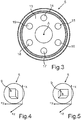
- Fig. 3 is shown in a schematic representation of the control element 5 with a view of an upper side 13.
- the control element 5 is shown in the closed state.
- control element 5 can be formed in one piece, which means that it can only be moved relative to the control element receptacle 4 as a whole.
- the operating element 5 may also be designed in several parts with respect to its housing and to the effect that the two parts are mutually relatively movable. In such a configuration, a first part in the arranged state can then be held on the operating element receptacle 4, for example by the magnetic holding force already explained above.
- the second part of the control element in particular the second part of a housing of the control element 5, in particular a cover, can then relative to this first part, in particular a first part of the Housing, to be moved, in particular to be rotated. As a result, an adjustment of operating conditions of the household appliance 1 can take place.
- Fig. 4 1 is a schematic illustration of the operating element 5 in an exemplary reference coordinate system.
- the reference coordinate system is here spanned by three mutually perpendicular spatial directions, namely the x-direction, the y-direction and the z-direction.
- the operating element 5 is placed in a touchdown position on the control element holder 4, as in Fig. 4 is shown, the absolute position of the operating element 5 is detected here.
- the acceleration values of the acceleration sensor 9 detect the corresponding position on the basis of the acceleration values in the three spatial directions.
- the absolute position in relation to a reference position which is here the horizontal and thus the y-direction, is indicated here.
- acceleration components or acceleration values in the three spatial directions which are always given as a function of the gravitational acceleration, then make it possible to determine the absolute position of the operating element 5.
- the sum of the squares of the acceleration value components A x , A y and A z corresponds to the square of a reference acceleration value, for example 1 g.
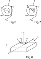
- Fig. 5 to Fig. 7 are more schematic representations shown in which the control element 5 in to Fig. 4 different absolute positions in space and thus in this defined coordinate system is arranged.
- each intermediate position of the control element 5 is also determined as an absolute position.
- a rotational movement of the operating element 5 about the longitudinal axis A and thus also a dynamic movement can be absolutely detected on the basis of the acceleration values.
- This can be detected with a further detection unit of the operating device 3.
- This detection unit can preferably be designed for optical detection, for example by infrared.
- a tap operation of the operating element 5 and / or a tilting movement of the operating element 5 depending on the axial acceleration values of the acceleration sensor 9 can be determined.
- a representation of a control element 5 is shown.
- several separate contact points 14, 15, 16, 17, 18 and 19 are formed by way of example. These lie in azimuthal direction about the longitudinal axis A at specific azimuth positions.
- the contact point 14 is drawn, which is formed along the longitudinal spatial direction.
- Fig. 8 drawn further contact point 19, which may be a second contact point, touched or acted with such force from above, that the operating element 5 tilts down and is tilted relative to the longitudinal axis A and thus to the longitudinal axis A, the acceleration sensor 9 performs a tilting movement or pitching movement about the y-space direction and a rolling movement about the x-space direction.
- a movement takes place which includes at least two different types of tilting movement, namely this tilting movement and this rolling movement.
- these different acceleration values in the respective spatial directions which then occur when the contact point 14 is actuated or when the contact point 19 is actuated can also be evaluated, and the actually touched contact point can also be detected.
- the operating condition of the household appliance 1 which accompanies this then actuation of the contact point can be selected and / or adjusted.
Landscapes
- Engineering & Computer Science (AREA)
- Chemical & Material Sciences (AREA)
- Combustion & Propulsion (AREA)
- Mechanical Engineering (AREA)
- General Engineering & Computer Science (AREA)
- Mechanical Control Devices (AREA)
- Switches With Compound Operations (AREA)
Applications Claiming Priority (1)
| Application Number | Priority Date | Filing Date | Title |
|---|---|---|---|
| DE102017207385.3A DE102017207385A1 (de) | 2017-05-03 | 2017-05-03 | Bedienvorrichtung für ein Haushaltsgerät mit einer Absolutpositionsbestimmung eines Bedienelements im Raum, sowie Haushaltsgerät |
Publications (2)
| Publication Number | Publication Date |
|---|---|
| EP3399239A1 true EP3399239A1 (fr) | 2018-11-07 |
| EP3399239B1 EP3399239B1 (fr) | 2021-08-11 |
Family
ID=62067555
Family Applications (1)
| Application Number | Title | Priority Date | Filing Date |
|---|---|---|---|
| EP18169630.3A Active EP3399239B1 (fr) | 2017-05-03 | 2018-04-26 | Appareil électroménager avec un dispositif de commande pourvu d'un dispositif de détermination de position absolue d'un élément de commande dans l'espace |
Country Status (2)
| Country | Link |
|---|---|
| EP (1) | EP3399239B1 (fr) |
| DE (1) | DE102017207385A1 (fr) |
Cited By (1)
| Publication number | Priority date | Publication date | Assignee | Title |
|---|---|---|---|---|
| WO2021122017A1 (fr) * | 2019-12-19 | 2021-06-24 | BSH Hausgeräte GmbH | Bouton de commande et procédé destinés à commander un appareil électroménager |
Citations (2)
| Publication number | Priority date | Publication date | Assignee | Title |
|---|---|---|---|---|
| EP2251762A2 (fr) | 2009-05-14 | 2010-11-17 | E.G.O. Elektro-Gerätebau GmbH | Dispositif de commande d'un appareil électrique |
| EP2983149A1 (fr) * | 2014-08-08 | 2016-02-10 | BSH Hausgeräte GmbH | Procede destine au fonctionnement d'un appareil menager dote d'une unite de commande externe a l'appareil et appareil menager |
-
2017
- 2017-05-03 DE DE102017207385.3A patent/DE102017207385A1/de not_active Withdrawn
-
2018
- 2018-04-26 EP EP18169630.3A patent/EP3399239B1/fr active Active
Patent Citations (2)
| Publication number | Priority date | Publication date | Assignee | Title |
|---|---|---|---|---|
| EP2251762A2 (fr) | 2009-05-14 | 2010-11-17 | E.G.O. Elektro-Gerätebau GmbH | Dispositif de commande d'un appareil électrique |
| EP2983149A1 (fr) * | 2014-08-08 | 2016-02-10 | BSH Hausgeräte GmbH | Procede destine au fonctionnement d'un appareil menager dote d'une unite de commande externe a l'appareil et appareil menager |
Cited By (1)
| Publication number | Priority date | Publication date | Assignee | Title |
|---|---|---|---|---|
| WO2021122017A1 (fr) * | 2019-12-19 | 2021-06-24 | BSH Hausgeräte GmbH | Bouton de commande et procédé destinés à commander un appareil électroménager |
Also Published As
| Publication number | Publication date |
|---|---|
| DE102017207385A1 (de) | 2018-11-08 |
| EP3399239B1 (fr) | 2021-08-11 |
Similar Documents
| Publication | Publication Date | Title |
|---|---|---|
| EP3554882B1 (fr) | Dispositif de commande comprenant un bouton de commande | |
| DE102018127494B4 (de) | Steuerelement, System, Verwendung und Verfahren | |
| DE102008031963A1 (de) | Drehsteuer- bzw. Bedienknopfanordnung | |
| EP2569592B1 (fr) | Sonde pour un appareil de mesure de coordonnées servant à la détermination de coordonnées dans l'espace sur un objet à mesurer | |
| EP1410507A1 (fr) | Dispositif optoelectronique de detection de position et de mouvement et procede correspondant | |
| EP0266713B1 (fr) | Dispositif pour mesurer des distances à partir d'une pièce d'oeuvre et pied à coulisse pourvu de mesure digitale de ces distances | |
| EP2821709B1 (fr) | Dispositif de commande doté d'un élément de commande ayant un élément adhésif sur le côté inférieur de l'élément de commande et appareil ménager doté d'un tel dispositif de commande | |
| DE102013225463A1 (de) | Bedienvorrichtung für ein elektrisches Gerät oder eine Anlage, insbesondere für eine Fahrzeugkomponente | |
| EP2503431A2 (fr) | Dispositif d'entrée avec réponse haptique | |
| DE102017106501A1 (de) | Bedieneinrichtung mit einem auf einem Touchscreen angeordneten Drehsteller, der eine verbesserte Drück- oder Kippfunktion aufweist | |
| DE102013002830A1 (de) | Manuell bedienbare Eingabevorrichtung mit Code-Erfassung | |
| EP3399239B1 (fr) | Appareil électroménager avec un dispositif de commande pourvu d'un dispositif de détermination de position absolue d'un élément de commande dans l'espace | |
| DE102019115950A1 (de) | Drehsteller mit Drückfunktion durch verbesserte Drehlagerung | |
| DE202015004771U1 (de) | Positionserfassungseinrichtung zum Erfassen einer Position eines Werkzeugs | |
| DE102015116290A1 (de) | Bedienelement mit Kraftsensormatrix | |
| DE102013212814A1 (de) | Bedienvorrichtung mit einem Bedienelement mit Magnete gehaltene Kappe und Sockel sowie Haushaltsgerät mit einer derartigen Bedienvorrichtung | |
| DE102018120561A1 (de) | Multifunktionales Bedienelement für ein Kraftfahrzeug | |
| DE202024100451U1 (de) | Bedieneinheit für ein Fahrzeug | |
| DE102017207386A1 (de) | Bedienvorrichtung für ein Haushaltsgerät mit einem Bedienelement mit Beschleunigungssensor zum Erkennen einer Kipp- und/oder Antippbetätigung, sowie Haushaltsgerät | |
| DE102016120638B4 (de) | Eingabegerät mit Betätigungsteil und magnetischem Messfeld zur Ermittlung eines Positionsparameters des Betätigungsteils | |
| DE102018202740A1 (de) | Bedienelement mit integriertem Gestenerkennungssensor, Bedienvorrichtung und Haushaltsgerät | |
| DE102020113075B4 (de) | Zieleinrichtung für eine Handfeuerwaffe | |
| DE102017110009B4 (de) | Stellantrieb mit Bedienvorrichtung und zugehöriges Verfahren zur Bedienung | |
| DE102017127222B4 (de) | Verfahren zum Betreiben einer kapazitiven Eingabevorrichtung; kapazitive Eingabevorrichtung; Kraftfahrzeug | |
| DE102021207897A1 (de) | Bedieneinheit für die Außenspiegel eines Fahrzeugs |
Legal Events
| Date | Code | Title | Description |
|---|---|---|---|
| PUAI | Public reference made under article 153(3) epc to a published international application that has entered the european phase |
Free format text: ORIGINAL CODE: 0009012 |
|
| STAA | Information on the status of an ep patent application or granted ep patent |
Free format text: STATUS: THE APPLICATION HAS BEEN PUBLISHED |
|
| AK | Designated contracting states |
Kind code of ref document: A1 Designated state(s): AL AT BE BG CH CY CZ DE DK EE ES FI FR GB GR HR HU IE IS IT LI LT LU LV MC MK MT NL NO PL PT RO RS SE SI SK SM TR |
|
| AX | Request for extension of the european patent |
Extension state: BA ME |
|
| STAA | Information on the status of an ep patent application or granted ep patent |
Free format text: STATUS: REQUEST FOR EXAMINATION WAS MADE |
|
| 17P | Request for examination filed |
Effective date: 20190507 |
|
| RBV | Designated contracting states (corrected) |
Designated state(s): AL AT BE BG CH CY CZ DE DK EE ES FI FR GB GR HR HU IE IS IT LI LT LU LV MC MK MT NL NO PL PT RO RS SE SI SK SM TR |
|
| STAA | Information on the status of an ep patent application or granted ep patent |
Free format text: STATUS: EXAMINATION IS IN PROGRESS |
|
| 17Q | First examination report despatched |
Effective date: 20201015 |
|
| GRAP | Despatch of communication of intention to grant a patent |
Free format text: ORIGINAL CODE: EPIDOSNIGR1 |
|
| STAA | Information on the status of an ep patent application or granted ep patent |
Free format text: STATUS: GRANT OF PATENT IS INTENDED |
|
| INTG | Intention to grant announced |
Effective date: 20210329 |
|
| GRAS | Grant fee paid |
Free format text: ORIGINAL CODE: EPIDOSNIGR3 |
|
| GRAA | (expected) grant |
Free format text: ORIGINAL CODE: 0009210 |
|
| STAA | Information on the status of an ep patent application or granted ep patent |
Free format text: STATUS: THE PATENT HAS BEEN GRANTED |
|
| AK | Designated contracting states |
Kind code of ref document: B1 Designated state(s): AL AT BE BG CH CY CZ DE DK EE ES FI FR GB GR HR HU IE IS IT LI LT LU LV MC MK MT NL NO PL PT RO RS SE SI SK SM TR |
|
| REG | Reference to a national code |
Ref country code: CH Ref legal event code: EP |
|
| REG | Reference to a national code |
Ref country code: DE Ref legal event code: R096 Ref document number: 502018006498 Country of ref document: DE |
|
| REG | Reference to a national code |
Ref country code: IE Ref legal event code: FG4D Free format text: LANGUAGE OF EP DOCUMENT: GERMAN Ref country code: AT Ref legal event code: REF Ref document number: 1419757 Country of ref document: AT Kind code of ref document: T Effective date: 20210915 |
|
| REG | Reference to a national code |
Ref country code: LT Ref legal event code: MG9D |
|
| REG | Reference to a national code |
Ref country code: NL Ref legal event code: MP Effective date: 20210811 |
|
| PG25 | Lapsed in a contracting state [announced via postgrant information from national office to epo] |
Ref country code: NO Free format text: LAPSE BECAUSE OF FAILURE TO SUBMIT A TRANSLATION OF THE DESCRIPTION OR TO PAY THE FEE WITHIN THE PRESCRIBED TIME-LIMIT Effective date: 20211111 Ref country code: PT Free format text: LAPSE BECAUSE OF FAILURE TO SUBMIT A TRANSLATION OF THE DESCRIPTION OR TO PAY THE FEE WITHIN THE PRESCRIBED TIME-LIMIT Effective date: 20211213 Ref country code: BG Free format text: LAPSE BECAUSE OF FAILURE TO SUBMIT A TRANSLATION OF THE DESCRIPTION OR TO PAY THE FEE WITHIN THE PRESCRIBED TIME-LIMIT Effective date: 20211111 Ref country code: LT Free format text: LAPSE BECAUSE OF FAILURE TO SUBMIT A TRANSLATION OF THE DESCRIPTION OR TO PAY THE FEE WITHIN THE PRESCRIBED TIME-LIMIT Effective date: 20210811 Ref country code: SE Free format text: LAPSE BECAUSE OF FAILURE TO SUBMIT A TRANSLATION OF THE DESCRIPTION OR TO PAY THE FEE WITHIN THE PRESCRIBED TIME-LIMIT Effective date: 20210811 Ref country code: RS Free format text: LAPSE BECAUSE OF FAILURE TO SUBMIT A TRANSLATION OF THE DESCRIPTION OR TO PAY THE FEE WITHIN THE PRESCRIBED TIME-LIMIT Effective date: 20210811 Ref country code: HR Free format text: LAPSE BECAUSE OF FAILURE TO SUBMIT A TRANSLATION OF THE DESCRIPTION OR TO PAY THE FEE WITHIN THE PRESCRIBED TIME-LIMIT Effective date: 20210811 Ref country code: ES Free format text: LAPSE BECAUSE OF FAILURE TO SUBMIT A TRANSLATION OF THE DESCRIPTION OR TO PAY THE FEE WITHIN THE PRESCRIBED TIME-LIMIT Effective date: 20210811 Ref country code: FI Free format text: LAPSE BECAUSE OF FAILURE TO SUBMIT A TRANSLATION OF THE DESCRIPTION OR TO PAY THE FEE WITHIN THE PRESCRIBED TIME-LIMIT Effective date: 20210811 |
|
| PG25 | Lapsed in a contracting state [announced via postgrant information from national office to epo] |
Ref country code: PL Free format text: LAPSE BECAUSE OF FAILURE TO SUBMIT A TRANSLATION OF THE DESCRIPTION OR TO PAY THE FEE WITHIN THE PRESCRIBED TIME-LIMIT Effective date: 20210811 Ref country code: LV Free format text: LAPSE BECAUSE OF FAILURE TO SUBMIT A TRANSLATION OF THE DESCRIPTION OR TO PAY THE FEE WITHIN THE PRESCRIBED TIME-LIMIT Effective date: 20210811 Ref country code: GR Free format text: LAPSE BECAUSE OF FAILURE TO SUBMIT A TRANSLATION OF THE DESCRIPTION OR TO PAY THE FEE WITHIN THE PRESCRIBED TIME-LIMIT Effective date: 20211112 |
|
| PG25 | Lapsed in a contracting state [announced via postgrant information from national office to epo] |
Ref country code: NL Free format text: LAPSE BECAUSE OF FAILURE TO SUBMIT A TRANSLATION OF THE DESCRIPTION OR TO PAY THE FEE WITHIN THE PRESCRIBED TIME-LIMIT Effective date: 20210811 |
|
| PG25 | Lapsed in a contracting state [announced via postgrant information from national office to epo] |
Ref country code: DK Free format text: LAPSE BECAUSE OF FAILURE TO SUBMIT A TRANSLATION OF THE DESCRIPTION OR TO PAY THE FEE WITHIN THE PRESCRIBED TIME-LIMIT Effective date: 20210811 |
|
| REG | Reference to a national code |
Ref country code: DE Ref legal event code: R097 Ref document number: 502018006498 Country of ref document: DE |
|
| PG25 | Lapsed in a contracting state [announced via postgrant information from national office to epo] |
Ref country code: SM Free format text: LAPSE BECAUSE OF FAILURE TO SUBMIT A TRANSLATION OF THE DESCRIPTION OR TO PAY THE FEE WITHIN THE PRESCRIBED TIME-LIMIT Effective date: 20210811 Ref country code: SK Free format text: LAPSE BECAUSE OF FAILURE TO SUBMIT A TRANSLATION OF THE DESCRIPTION OR TO PAY THE FEE WITHIN THE PRESCRIBED TIME-LIMIT Effective date: 20210811 Ref country code: RO Free format text: LAPSE BECAUSE OF FAILURE TO SUBMIT A TRANSLATION OF THE DESCRIPTION OR TO PAY THE FEE WITHIN THE PRESCRIBED TIME-LIMIT Effective date: 20210811 Ref country code: EE Free format text: LAPSE BECAUSE OF FAILURE TO SUBMIT A TRANSLATION OF THE DESCRIPTION OR TO PAY THE FEE WITHIN THE PRESCRIBED TIME-LIMIT Effective date: 20210811 Ref country code: CZ Free format text: LAPSE BECAUSE OF FAILURE TO SUBMIT A TRANSLATION OF THE DESCRIPTION OR TO PAY THE FEE WITHIN THE PRESCRIBED TIME-LIMIT Effective date: 20210811 Ref country code: AL Free format text: LAPSE BECAUSE OF FAILURE TO SUBMIT A TRANSLATION OF THE DESCRIPTION OR TO PAY THE FEE WITHIN THE PRESCRIBED TIME-LIMIT Effective date: 20210811 |
|
| PLBE | No opposition filed within time limit |
Free format text: ORIGINAL CODE: 0009261 |
|
| STAA | Information on the status of an ep patent application or granted ep patent |
Free format text: STATUS: NO OPPOSITION FILED WITHIN TIME LIMIT |
|
| 26N | No opposition filed |
Effective date: 20220512 |
|
| PG25 | Lapsed in a contracting state [announced via postgrant information from national office to epo] |
Ref country code: IT Free format text: LAPSE BECAUSE OF FAILURE TO SUBMIT A TRANSLATION OF THE DESCRIPTION OR TO PAY THE FEE WITHIN THE PRESCRIBED TIME-LIMIT Effective date: 20210811 |
|
| PG25 | Lapsed in a contracting state [announced via postgrant information from national office to epo] |
Ref country code: SI Free format text: LAPSE BECAUSE OF FAILURE TO SUBMIT A TRANSLATION OF THE DESCRIPTION OR TO PAY THE FEE WITHIN THE PRESCRIBED TIME-LIMIT Effective date: 20210811 |
|
| REG | Reference to a national code |
Ref country code: CH Ref legal event code: PL |
|
| GBPC | Gb: european patent ceased through non-payment of renewal fee |
Effective date: 20220426 |
|
| REG | Reference to a national code |
Ref country code: BE Ref legal event code: MM Effective date: 20220430 |
|
| PG25 | Lapsed in a contracting state [announced via postgrant information from national office to epo] |
Ref country code: MC Free format text: LAPSE BECAUSE OF FAILURE TO SUBMIT A TRANSLATION OF THE DESCRIPTION OR TO PAY THE FEE WITHIN THE PRESCRIBED TIME-LIMIT Effective date: 20210811 Ref country code: LU Free format text: LAPSE BECAUSE OF NON-PAYMENT OF DUE FEES Effective date: 20220426 Ref country code: LI Free format text: LAPSE BECAUSE OF NON-PAYMENT OF DUE FEES Effective date: 20220430 Ref country code: GB Free format text: LAPSE BECAUSE OF NON-PAYMENT OF DUE FEES Effective date: 20220426 Ref country code: FR Free format text: LAPSE BECAUSE OF NON-PAYMENT OF DUE FEES Effective date: 20220430 Ref country code: CH Free format text: LAPSE BECAUSE OF NON-PAYMENT OF DUE FEES Effective date: 20220430 |
|
| PG25 | Lapsed in a contracting state [announced via postgrant information from national office to epo] |
Ref country code: BE Free format text: LAPSE BECAUSE OF NON-PAYMENT OF DUE FEES Effective date: 20220430 |
|
| PG25 | Lapsed in a contracting state [announced via postgrant information from national office to epo] |
Ref country code: IE Free format text: LAPSE BECAUSE OF NON-PAYMENT OF DUE FEES Effective date: 20220426 |
|
| PG25 | Lapsed in a contracting state [announced via postgrant information from national office to epo] |
Ref country code: HU Free format text: LAPSE BECAUSE OF FAILURE TO SUBMIT A TRANSLATION OF THE DESCRIPTION OR TO PAY THE FEE WITHIN THE PRESCRIBED TIME-LIMIT; INVALID AB INITIO Effective date: 20180426 |
|
| PG25 | Lapsed in a contracting state [announced via postgrant information from national office to epo] |
Ref country code: MK Free format text: LAPSE BECAUSE OF FAILURE TO SUBMIT A TRANSLATION OF THE DESCRIPTION OR TO PAY THE FEE WITHIN THE PRESCRIBED TIME-LIMIT Effective date: 20210811 Ref country code: CY Free format text: LAPSE BECAUSE OF FAILURE TO SUBMIT A TRANSLATION OF THE DESCRIPTION OR TO PAY THE FEE WITHIN THE PRESCRIBED TIME-LIMIT Effective date: 20210811 |
|
| REG | Reference to a national code |
Ref country code: AT Ref legal event code: MM01 Ref document number: 1419757 Country of ref document: AT Kind code of ref document: T Effective date: 20230426 |
|
| PG25 | Lapsed in a contracting state [announced via postgrant information from national office to epo] |
Ref country code: TR Free format text: LAPSE BECAUSE OF FAILURE TO SUBMIT A TRANSLATION OF THE DESCRIPTION OR TO PAY THE FEE WITHIN THE PRESCRIBED TIME-LIMIT Effective date: 20210811 |
|
| PG25 | Lapsed in a contracting state [announced via postgrant information from national office to epo] |
Ref country code: AT Free format text: LAPSE BECAUSE OF NON-PAYMENT OF DUE FEES Effective date: 20230426 |
|
| PG25 | Lapsed in a contracting state [announced via postgrant information from national office to epo] |
Ref country code: AT Free format text: LAPSE BECAUSE OF NON-PAYMENT OF DUE FEES Effective date: 20230426 |
|
| PG25 | Lapsed in a contracting state [announced via postgrant information from national office to epo] |
Ref country code: MT Free format text: LAPSE BECAUSE OF FAILURE TO SUBMIT A TRANSLATION OF THE DESCRIPTION OR TO PAY THE FEE WITHIN THE PRESCRIBED TIME-LIMIT Effective date: 20210811 |
|
| PGFP | Annual fee paid to national office [announced via postgrant information from national office to epo] |
Ref country code: DE Payment date: 20250430 Year of fee payment: 8 |
|
| PGFP | Annual fee paid to national office [announced via postgrant information from national office to epo] |
Ref country code: AT Payment date: 20260410 Year of fee payment: 5 |