EP3399285A1 - Débitmètre à section en forme de tuyau conique utilisant une mesure de distance magnétostrictive - Google Patents
Débitmètre à section en forme de tuyau conique utilisant une mesure de distance magnétostrictive Download PDFInfo
- Publication number
- EP3399285A1 EP3399285A1 EP16881902.7A EP16881902A EP3399285A1 EP 3399285 A1 EP3399285 A1 EP 3399285A1 EP 16881902 A EP16881902 A EP 16881902A EP 3399285 A1 EP3399285 A1 EP 3399285A1
- Authority
- EP
- European Patent Office
- Prior art keywords
- float
- taper pipe
- pulse
- magnetostrictive
- comparison voltage
- Prior art date
- Legal status (The legal status is an assumption and is not a legal conclusion. Google has not performed a legal analysis and makes no representation as to the accuracy of the status listed.)
- Withdrawn
Links
Images

Classifications
-
- G—PHYSICS
- G01—MEASURING; TESTING
- G01F—MEASURING VOLUME, VOLUME FLOW, MASS FLOW OR LIQUID LEVEL; METERING BY VOLUME
- G01F1/00—Measuring the volume flow or mass flow of fluid or fluent solid material wherein the fluid passes through a meter in a continuous flow
- G01F1/05—Measuring the volume flow or mass flow of fluid or fluent solid material wherein the fluid passes through a meter in a continuous flow by using mechanical effects
- G01F1/20—Measuring the volume flow or mass flow of fluid or fluent solid material wherein the fluid passes through a meter in a continuous flow by using mechanical effects by detection of dynamic effects of the flow
- G01F1/22—Measuring the volume flow or mass flow of fluid or fluent solid material wherein the fluid passes through a meter in a continuous flow by using mechanical effects by detection of dynamic effects of the flow by variable-area meters, e.g. rotameters
- G01F1/24—Measuring the volume flow or mass flow of fluid or fluent solid material wherein the fluid passes through a meter in a continuous flow by using mechanical effects by detection of dynamic effects of the flow by variable-area meters, e.g. rotameters with magnetic or electric coupling to the indicating device
-
- G—PHYSICS
- G01—MEASURING; TESTING
- G01F—MEASURING VOLUME, VOLUME FLOW, MASS FLOW OR LIQUID LEVEL; METERING BY VOLUME
- G01F1/00—Measuring the volume flow or mass flow of fluid or fluent solid material wherein the fluid passes through a meter in a continuous flow
- G01F1/05—Measuring the volume flow or mass flow of fluid or fluent solid material wherein the fluid passes through a meter in a continuous flow by using mechanical effects
- G01F1/20—Measuring the volume flow or mass flow of fluid or fluent solid material wherein the fluid passes through a meter in a continuous flow by using mechanical effects by detection of dynamic effects of the flow
- G01F1/22—Measuring the volume flow or mass flow of fluid or fluent solid material wherein the fluid passes through a meter in a continuous flow by using mechanical effects by detection of dynamic effects of the flow by variable-area meters, e.g. rotameters
-
- G—PHYSICS
- G01—MEASURING; TESTING
- G01F—MEASURING VOLUME, VOLUME FLOW, MASS FLOW OR LIQUID LEVEL; METERING BY VOLUME
- G01F15/00—Details of, or accessories for, apparatus of groups G01F1/00 - G01F13/00 insofar as such details or appliances are not adapted to particular types of such apparatus
- G01F15/06—Indicating or recording devices
-
- G—PHYSICS
- G01—MEASURING; TESTING
- G01F—MEASURING VOLUME, VOLUME FLOW, MASS FLOW OR LIQUID LEVEL; METERING BY VOLUME
- G01F15/00—Details of, or accessories for, apparatus of groups G01F1/00 - G01F13/00 insofar as such details or appliances are not adapted to particular types of such apparatus
- G01F15/06—Indicating or recording devices
- G01F15/061—Indicating or recording devices for remote indication
- G01F15/063—Indicating or recording devices for remote indication using electrical means
-
- G—PHYSICS
- G01—MEASURING; TESTING
- G01F—MEASURING VOLUME, VOLUME FLOW, MASS FLOW OR LIQUID LEVEL; METERING BY VOLUME
- G01F23/00—Indicating or measuring liquid level or level of fluent solid material, e.g. indicating in terms of volume or indicating by means of an alarm
- G01F23/30—Indicating or measuring liquid level or level of fluent solid material, e.g. indicating in terms of volume or indicating by means of an alarm by floats
- G01F23/64—Indicating or measuring liquid level or level of fluent solid material, e.g. indicating in terms of volume or indicating by means of an alarm by floats of the free float type without mechanical transmission elements
- G01F23/72—Indicating or measuring liquid level or level of fluent solid material, e.g. indicating in terms of volume or indicating by means of an alarm by floats of the free float type without mechanical transmission elements using magnetically actuated indicating means
-
- G—PHYSICS
- G01—MEASURING; TESTING
- G01S—RADIO DIRECTION-FINDING; RADIO NAVIGATION; DETERMINING DISTANCE OR VELOCITY BY USE OF RADIO WAVES; LOCATING OR PRESENCE-DETECTING BY USE OF THE REFLECTION OR RERADIATION OF RADIO WAVES; ANALOGOUS ARRANGEMENTS USING OTHER WAVES
- G01S13/00—Systems using the reflection or reradiation of radio waves, e.g. radar systems; Analogous systems using reflection or reradiation of waves whose nature or wavelength is irrelevant or unspecified
- G01S13/02—Systems using reflection of radio waves, e.g. primary radar systems; Analogous systems
- G01S13/06—Systems determining position data of a target
- G01S13/08—Systems for measuring distance only
- G01S13/10—Systems for measuring distance only using transmission of interrupted, pulse modulated waves
Definitions
- the present invention relates to a taper pipe-shaped area flow meter, and more specifically, to a taper pipe-shaped area flow meter using a magnetostrictive distance measurement method in which a flow rate may be accurately measured by measuring a height of a float through a magnetostrictive method.
- a taper pipe-shaped area flow meter has a simple structure and a degree of accuracy high enough to be used for calibration of a flow meter, but may not generate a measured value as an electric signal, and thus utilization thereof is limited to a field in which a flow rate is visually checked through a field indicator by which the measured value is seen through a gradation. Therefore, the taper pipe-shaped area flow meter may not be used in a flow rate control system for a process control.
- a flow path of a fluid is fixed, and a pressure difference measured at up and down streams of a fastener, has a functional relation with a flow rate.
- an area flow meter has a structure in which a flow path of a fluid is changed according to a flow rate, a pressure difference between upper and lower sides of a float is always constantly maintained. That is, in the area flow meter, since a change in an area of a flow path through which a fluid flows is a function of a flow rate, the change in the area of the fluid may be linearly related to the flow rate when a taper pipe is used.
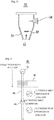
- a taper pipe-shaped area flow meter 50 as illustrated in FIG. 1 which is one of the most simple taper pipe-shaped area flow meters, includes a taper transparent glass or plastic pipe 51 in which an inlet 53 and an outlet 54 are formed and a float 52 moves vertically in the pipe.
- a taper transparent glass or plastic pipe 51 in which an inlet 53 and an outlet 54 are formed
- a float 52 moves vertically in the pipe.
- a reason for such a motion is that a flow of the fluid serves as a fastener for the float 52 and a pressure difference occurs at a front and a rear of the float 52.
- a flow of the fluid serves as a fastener for the float 52 and a pressure difference occurs at a front and a rear of the float 52.
- a flow cross sectional area of the taper pipe 51 determined according to a position to which the float 52 moved vertically is proportional to a flow rate
- the flow rate is measured by detecting a position to which the float 52 moved vertically.
- a float type area flow meter which is published in the Patent Publication (A) as Publication No. 2002-0006138 , includes a main body having a taper flow path in which a diameter thereof decreases downward, a lower end thereof communicates with an inlet of the flow path, and an upper end thereof communicates with an outlet of the flow path, a float accommodated in the taper flow path of the main body and configured to vertically move according to a flow rate, and a distance measurement unit which is installed above the taper flow path of the main body receives relational data between a distance to the float therefrom and a flow rate, measures a position of the float, calculates a flow rate from the relational data between the distance and the flow rate, and outputs the flow rate, and the distance measurement unit includes a laser or ultrasonic sensor located directly above the taper flow path and configured to measure a distance to the float therefrom and output a measured value as an electric signal.
- a distance measurement technology through a radar or laser method uses a microwave and a time period, which is measured between radiation of a pulse and receiving of the pulse reflected by a target object and returned to its radiation position, is too short due to properties of a radio wave, it is not suitable to measure a short distance of 50 cm or less, and since refraction and diffraction are severe due to a property of wave propagation in a distance measurement technology through an ultrasonic wave method and a propagation speed based on a transmitting medium is not constant, there is a problem in that the technology may not be applied for measuring distance due to a large error in measurement.
- the present invention is directed to providing a taper pipe-shaped area flow meter using a magnetostrictive distance measurement method in which a height of a float is measured through a magnetostrictive method to accurately measure a flow rate.
- One aspect of the present invention provides a taper pipe-shaped area flow meter using a magnetostrictive distance measurement method, including: a taper pipe including an inlet at a lower portion thereof and an outlet at an upper portion thereof and formed in a taper shape having a diameter decreasing downward; a float in which a magnet is embedded and a height of the float is changed according to a flow rate in the taper pipe; a probe shaft in which a magnetrostrictive line is embedded and which is installed in the taper pipe and detects a position of the float through a magnetostrictive method; and a magnetostrictive distance measuring part, which is configured to apply a pulse to the probe shaft, receive a signal reflected by the magnet of the float, measure a position of the float, and calculate a flow rate from the position of the float.
- the area flow meter may directly display the flow rate on a main body or transmit measured data of the distance measuring part to the outside as an electric signal
- the magnetostrictive distance measuring part may include a pulse generator configured to generate a predetermined pulse according to a start signal and apply the pulse to the probe shaft, a reflected wave receiver configured to receive a reflected wave signal due to the pulse from the probe shaft, a comparator configured to compare a signal received by the reflected wave receiver with a predetermined comparison voltage and output a stop signal, a comparison voltage generator configured to supply the comparison voltage to the comparator according to a control signal, and a microprocessor configured to control the comparison voltage generator to supply a first voltage as the comparison voltage when measurement is required, transmit the start signal to the pulse generator to generate the pulse, start an internal timer, try to detect data received according to an output of the comparator, repeat a process of pulse application and reception by controlling the comparison voltage generator to decrease the comparison voltage when there are no received signals, store the comparison voltage at that time as an upper limit value of the received signal when
- the magnetostrictive distance measuring part may further include a communication part configured to transmit measured data, and the microprocessor may also calculate a flow rate from a height of a liquid, receive a temperature from a temperature sensor to convert the flow rate into a net flow rate, and transmit the net flow rate to the outside through the communication part.
- FIG. 2 is a view for describing a magnetostrictive distance measurement method applied to the present invention.
- a taper pipe-shaped area flow meter using the magnetostrictive distance measurement method is a meter in which a magnetostrictive method is applied to measure a distance to a float of the taper pipe-shaped area flow meter so as to inexpensively and accurately measure a height of the float. That is, the taper pipe-shaped area flow meter has a degree of accuracy high enough to be applied to calibration of a flow meter, but since the taper pipe-shaped area flow meter cannot generate a measured value as an electric signal, the taper pipe-shaped area flow meter is limited to a field in which a flow rate is visually checked.
- the taper pipe-shaped area flow meter accurately measures a position of the float in a taper pipe through the magnetostrictive method and supplies a measured value as an electric signal in order to use the electric signal in various fields such as a process control.
- a distance measurement technology through the magnetostrictive method applied to the present invention uses a magnetostrictive phenomenon in which an elastic wave is generated when a magnetic field is applied to a magnetic material.
- the distance measurement technology through the magnetostrictive method is a technology in which, when a float in which a permanent magnet 64 is embedded is disposed on a magnetrostrictive line 63 to generate a transversal magnetic field and a pulse application unit 61 applies a pulse to the magnetrostrictive line 63 and generates a magnetic field in a direction of a shaft, an elastic wave is generated at an intersection of the permanent magnet 64 and the magnetic field, and a time period, which is measured between application of the pulse and receiving of the elastic wave by a receiver 62 wherein the elastic wave is transmitted through the magnetrostrictive line 63, is measured to measure a distance from the pulse application unit 61 to the float in which the permanent magnet 64 is embedded.
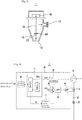
- FIG. 3 is a schematic view illustrating a taper pipe-shaped area flow meter using the magnetostrictive distance measurement method according to the present invention
- FIG. 4 is a block diagram of a configuration of a magnetostrictive distance measuring part illustrated in FIG. 3 .
- a taper pipe-shaped area flow meter 1 using the magnetostrictive distance measurement method includes a taper pipe 10, a float 20 in which a permanent magnet 22 is installed, a probe shaft 30 in which a magnetrostrictive line is embedded, and a magnetostrictive distance measuring part 40 according to an embodiment of the present invention.
- the area flow meter 1 of the present invention includes the taper pipe 10, which has an inlet 12 at a lower end thereof and an outlet 14 at an upper portion thereof, formed in a taper shape, the float 20 in which the permanent magnet 22 is embedded, and a height of the float 20 is changed according to a flow rate in the taper pipe 10, the probe shaft 30 in which the magnetrostrictive line is embedded and which is installed at a center of the taper pipe 10 to detect a position of the float 20 through the magnetostrictive method, and the magnetostrictive distance measuring part 40 configured to measure a position of the float 20 by applying a pulse to the probe shaft 30 and receiving a signal reflected by the float 20 to calculate a flow rate.
- the distance measuring part 40 may display a measured flow rate value on a main body or supply the measured flow rate value as an electric signal to the outside through a communication port to display the electric signal on an external liquid crystal display (LCD) or use the electric signal for other purposes such as a process control.
- LCD liquid crystal display
- the float 20 may be formed in a structure in which a float of a conventional taper pipe-shaped area flow meter is used as it is and the cylindrical permanent magnet 22 is embedded in the float.
- the magnetostrictive distance measuring part 40 includes a microprocessor unit (MPU) 41, a pulse generator 42, a pulse application part 43, a reflected wave receiver 44, an amplifier 45, a band pass filter (BPF) 46, a comparison voltage generator 47, a comparator 48, and a communication part 49.
- MPU microprocessor unit
- BPF band pass filter
- the MPU 41 includes a central processing unit (CPU) core, an embedded timer, an electrically erasable programmable read-only memory (EEPROM), digital input and output terminals, analog input and output terminals, and the like, and executes a measurement software according to the present invention. That is, when measurement is required, the MPU 41 controls the comparison voltage generator 47 to supply a first voltage as a comparison voltage, transmits a start signal to the pulse generator 42 to generate a pulse, and starts an internal timer.
- CPU central processing unit
- EEPROM electrically erasable programmable read-only memory
- the MPU 41 when the MPU 41 tries to detect data received according to an output of the comparator 48 and there are no received signals, the MPU 41 repeats a process of pulse application and reception by controlling the comparison voltage generator 47 to decrease the comparison voltage, and when a received signal is detected for a first time, the MPU 41 stores a comparison voltage at that time as an upper limit value of the received signal. In addition, the MPU again repeats the process of pulse application and reception while decreasing the comparison voltage, and when a pulse width of the received signal becomes a predetermined value or more, the MPU 41 stores the comparison voltage at that time as a lower limit value of the received signal and sets a center value between the upper limit value and the lower limit value as a reference comparison voltage.
- the MPU 41 transmits the start signal to the pulse generator 42 for measurement so as to generate a pulse and starts the internal timer, and when the comparator 48 compares the received signal with the reference comparison voltage and outputs the stop signal, the MPU 41 reads a value from the timer and calculates a time period between application of the pulse and receiving of a reflected wave (elastic wave) and calculates a height of a surface of a liquid from the time period.
- a reflected wave elastic wave
- the pulse generator 42 is formed with a multistage double voltage circuit, and when a start signal is transmitted from the MPU 41 to the pulse generator 42, the pulse generator 42 generates a pulse having a predetermined magnitude and applies the pulse to the magnetrostrictive line in the probe shaft 30 through the pulse application part 43.
- the amplifier 45 receives and amplifies a reflected wave (elastic wave) signal from the reflected wave receiver 44 through the magnetrostrictive line in the probe shaft after application of a pulse, the BPF 46 removes a noise of an unnecessary band for a first time, and the comparator 48 compares a filtered received signal with the comparison voltage and transmits a comparison result to the MPU 41 as a stop signal. Accordingly, the MPU 41 may calculate a time period between application of a pulse and receiving of a reflected wave by detecting a time at which the timer is ended by a stop signal after the MPU 41 starts the internal timer using a start signal.
- a reflected wave elastic wave
- the comparison voltage generator 47 selects one among multistage comparison voltages according to a control of the MPU 41 and outputs a selected multistage comparison voltage to the comparator 48, and the communication part 49 performs communication between a display apparatus or external host apparatus (not shown) and the processor 41. That is, data of a measurement result provided by the MPU 41 may be transmitted to and displayed on the display apparatus (not shown).
- the taper pipe-shaped area flow meter 1 configured as described above and using the magnetostrictive distance measurement method according to the present invention applies a pulse to the magnetrostrictive line of the probe shaft 30, generates a magnetic field in a direction of the shaft, receives an elastic wave generated at an intersection between the permanent magnet 22 of the float 20 and the magnetic field, transmits a pulse to measure a time period between transmission of the pulse and receiving of the elastic wave transmitted through the magnetrostrictive line, detects a position of the float 20, and calculates a flow rate.
- FIG. 5 is a view illustrating an example of the taper pipe-shaped area flow meter using the magnetostrictive distance measurement method according to the present invention.
- an inlet 102 and an outlet 104 are disposed in a row, flanges 106a and 106b are respectively formed at the inlet 102 and the outlet 104 and perpendicularly installed on a pipe through which a fluid flows such that a flow rate may be measured.
- a taper pipe 110 is coupled to and stably supported by a support rod 108 through a nut and bolt method, and a float 130 fitted to the probe shaft 120 and configured to vertically move along the shaft 120 according to a fluid flow and a probe shaft 120 in which a magnetrostrictive line 122 is embedded are disposed in an inner space of the taper pipe 110.
- a permanent magnet 132 is embedded in the float 130, and a pulse application part 142 for applying a pulse and a receiver 144 for receiving an elastic wave are disposed at an upper end 140 of the probe shaft 130 and connected to an external control box 200 through four lines.
- the control box 200 installed outside the taper pipe 110 includes a magnetostrictive circuit 210, which is configured to apply a pulse to the magnetrostrictive line 122, process a signal received by the receiver 144, calculate a height (distance) of the float 130, and convert the calculated height into a flow rate value to measure a flow rate, a character type LCD 220 for displaying data of a flow rate measured by the magnetostrictive circuit 210, a graphic type LCD 230 for displaying data of the flow rate measured by the magnetostrictive circuit 210, and a communication part 240 for transmitting data of the flow rate measured by the magnetostrictive circuit 210 to a remote apparatus.
- the communication part 240 may transmit measured data to a dedicated display apparatus 300 using a wired/wireless signal, and thus the dedicated display apparatus 300 may display information such as a measured flow rate and the like at a management center and the like.
- FIG. 6 is a view illustrating another example of the taper pipe-shaped area flow meter using the magnetostrictive distance measurement method according to the present invention.
- the flow meters 100-1 to 100-N and an integrated display apparatus 400 may be connected by a wired/wireless communication method to display data together.
- the integrated display apparatus 400 includes a communication part 410 for communicating with the flow meters 100-1 to 100-N, an operating part 440 for inputting an operation, an LCD 430 for displaying measured values of the flow meters 100-1 to 100-N, a printer 450 for printing the measured values, and a CPU 420 for controlling an overall operation of the integrated display apparatus 400, and displays the measured values received from the flow meters 100-1 to 100-N on the LCD 430 or prints the measured values using the printer 450 through a method selected according to an input of the operating part 440.
- the taper pipe-shaped area flow meter using the magnetostrictive distance measurement method according to the present invention has high accuracy because the magnetostrictive method is applied thereto and can inexpensively measure a flow rate by using a simple mechanical structure.
- a degree of accuracy of distance measurement is 0.1 mm and a measurement interval thereof is 0.1 seconds, a height of the float can be accurately measured, and thus a flow rate can be precisely measured.
- the taper pipe-shaped area flow meter using the magnetostrictive distance measurement method according to the present invention measures a position of the float using the magnetostrictive method, there is an advantage in that a measured value is provided as an electric signal and used in various fields such as a process control.
Landscapes
- Physics & Mathematics (AREA)
- General Physics & Mathematics (AREA)
- Fluid Mechanics (AREA)
- Engineering & Computer Science (AREA)
- Radar, Positioning & Navigation (AREA)
- Remote Sensing (AREA)
- Computer Networks & Wireless Communication (AREA)
- Measuring Volume Flow (AREA)
Applications Claiming Priority (2)
| Application Number | Priority Date | Filing Date | Title |
|---|---|---|---|
| KR1020150190662A KR101630301B1 (ko) | 2015-12-31 | 2015-12-31 | 자기왜곡방식의 거리측정을 이용한 테이퍼관형 면적식 유량계 |
| PCT/KR2016/006313 WO2017115949A1 (fr) | 2015-12-31 | 2016-06-14 | Débitmètre à section en forme de tuyau conique utilisant une mesure de distance magnétostrictive |
Publications (2)
| Publication Number | Publication Date |
|---|---|
| EP3399285A1 true EP3399285A1 (fr) | 2018-11-07 |
| EP3399285A4 EP3399285A4 (fr) | 2019-08-07 |
Family
ID=56192030
Family Applications (1)
| Application Number | Title | Priority Date | Filing Date |
|---|---|---|---|
| EP16881902.7A Withdrawn EP3399285A4 (fr) | 2015-12-31 | 2016-06-14 | Débitmètre à section en forme de tuyau conique utilisant une mesure de distance magnétostrictive |
Country Status (8)
| Country | Link |
|---|---|
| US (1) | US10605634B2 (fr) |
| EP (1) | EP3399285A4 (fr) |
| JP (1) | JP2018534580A (fr) |
| KR (1) | KR101630301B1 (fr) |
| CN (1) | CN108431553B (fr) |
| BR (1) | BR112018010592A2 (fr) |
| RU (1) | RU2018121649A (fr) |
| WO (1) | WO2017115949A1 (fr) |
Families Citing this family (4)
| Publication number | Priority date | Publication date | Assignee | Title |
|---|---|---|---|---|
| CN107490409B (zh) * | 2017-08-09 | 2020-07-21 | 辽宁航宇星物联仪表科技有限公司 | 一种户用超声波水表防错波改进方法 |
| KR102054932B1 (ko) | 2019-05-28 | 2019-12-11 | 성재훈 | 면적식 유량계 |
| KR102674298B1 (ko) | 2023-09-05 | 2024-06-10 | 성재훈 | 디지털 면적식 유량계 |
| CN121026259B (zh) * | 2025-10-29 | 2026-01-06 | 青岛长远检测技术有限公司 | 一种自动连续测量的高效皂膜流量计及方法 |
Family Cites Families (30)
| Publication number | Priority date | Publication date | Assignee | Title |
|---|---|---|---|---|
| US3894433A (en) * | 1974-02-13 | 1975-07-15 | Fischer & Porter Co | Rotameter system with electrical read-out |
| JPS55150315U (fr) * | 1979-04-13 | 1980-10-29 | ||
| JPS632115U (fr) * | 1986-06-24 | 1988-01-08 | ||
| US5014559A (en) * | 1990-07-11 | 1991-05-14 | Lew Hyok S | Rotameter with read-out device |
| US5193400A (en) * | 1991-05-10 | 1993-03-16 | Lew Hyok S | Universal rotameter |
| JPH0794997B2 (ja) * | 1992-06-30 | 1995-10-11 | 株式会社エスシーエー | 自己クリーニング付流量計 |
| US5347875A (en) * | 1993-03-25 | 1994-09-20 | Lew Hyok S | Capacitor-coupled ohmic resistance position sensor |
| US5655568A (en) * | 1995-08-08 | 1997-08-12 | Bhargava; Raj | Passive flow regulating device |
| JP3422673B2 (ja) * | 1997-12-26 | 2003-06-30 | 日東精工株式会社 | 流量計 |
| JPH11325986A (ja) * | 1998-05-15 | 1999-11-26 | Wako Pure Chem Ind Ltd | 流量計目盛部に異物が付着しないようにする装置 |
| DE20009024U1 (de) * | 2000-05-19 | 2000-08-17 | GEMÜ Gebrüder Müller Apparatebau GmbH & Co. KG, 74653 Ingelfingen | Durchflußmesser |
| KR20020006138A (ko) | 2000-07-11 | 2002-01-19 | 이구택 | 플로트형 면적 유량계 |
| CN1350164A (zh) * | 2000-10-25 | 2002-05-22 | 北京特力声技术有限责任公司 | 超声波测量大型油罐液位的方法 |
| WO2005106530A1 (fr) * | 2004-04-28 | 2005-11-10 | Matsushita Electric Industrial Co., Ltd. | Découvreur de plage d'ultrasons |
| JP2006153632A (ja) * | 2004-11-29 | 2006-06-15 | Tokyo Keiso Co Ltd | 流量計 |
| KR100650526B1 (ko) | 2005-07-12 | 2006-11-29 | 주식회사 우당기술산업 | 면적식 유량계 |
| JP5078060B2 (ja) * | 2006-04-03 | 2012-11-21 | 東京計装株式会社 | 流量計 |
| US20080047359A1 (en) * | 2006-08-25 | 2008-02-28 | Yang Zheng | A digital gas flowmeter (DigiFlux™) using hall effect gas sensor for medical/science use |
| CN100578137C (zh) * | 2007-02-08 | 2010-01-06 | 北京航空航天大学 | 磁致伸缩式位移传感器 |
| CN101246213A (zh) * | 2008-02-22 | 2008-08-20 | 王建平 | 一种双比较器式超声波测距装置 |
| JP5066465B2 (ja) * | 2008-03-10 | 2012-11-07 | 関西電力株式会社 | 既設ケーブル油槽用油量センサの取付構造 |
| CN101988842B (zh) * | 2009-07-31 | 2012-06-27 | 胜利油田胜利动力机械集团有限公司 | 磁耦合浮子式气体流量测量计 |
| US8256304B2 (en) * | 2010-04-30 | 2012-09-04 | Waukee Engineering Company, Inc. | Float type flow meter |
| KR101235793B1 (ko) * | 2011-02-23 | 2013-02-21 | (주) 다인레벨 | 자기장 왜곡 방식의 액면 높이 측정장치 및 방법 |
| CN102680032A (zh) * | 2012-05-25 | 2012-09-19 | 来卫国 | 磁位移浮子流量计 |
| JP2014009971A (ja) * | 2012-06-28 | 2014-01-20 | Nihon Tokushu Keiki Seisakusho:Kk | 流量計 |
| CN203502061U (zh) * | 2013-10-14 | 2014-03-26 | 然斯康波达机电设备(深圳)有限公司 | 一种转子流量计 |
| KR101526962B1 (ko) * | 2015-01-22 | 2015-06-11 | (주)동명엔터프라이즈 | 토양, 지하수오염 예방을 위한 주유소의 누유 검출 및 유류 저장시설용 레벨 측정 시스템 |
| CN204924377U (zh) * | 2015-05-13 | 2015-12-30 | 北京农业智能装备技术研究中心 | 监测农机油箱油位的系统 |
| EP3452244B1 (fr) * | 2016-05-04 | 2021-04-21 | Dennison, William, E. | Débitmètre à gaz |
-
2015
- 2015-12-31 KR KR1020150190662A patent/KR101630301B1/ko active Active
-
2016
- 2016-06-14 RU RU2018121649A patent/RU2018121649A/ru not_active Application Discontinuation
- 2016-06-14 US US16/063,856 patent/US10605634B2/en active Active
- 2016-06-14 CN CN201680070279.8A patent/CN108431553B/zh not_active Expired - Fee Related
- 2016-06-14 WO PCT/KR2016/006313 patent/WO2017115949A1/fr not_active Ceased
- 2016-06-14 BR BR112018010592-9A patent/BR112018010592A2/pt active Search and Examination
- 2016-06-14 JP JP2018526626A patent/JP2018534580A/ja active Pending
- 2016-06-14 EP EP16881902.7A patent/EP3399285A4/fr not_active Withdrawn
Also Published As
| Publication number | Publication date |
|---|---|
| KR101630301B1 (ko) | 2016-06-14 |
| EP3399285A4 (fr) | 2019-08-07 |
| WO2017115949A1 (fr) | 2017-07-06 |
| JP2018534580A (ja) | 2018-11-22 |
| RU2018121649A3 (fr) | 2020-01-31 |
| US10605634B2 (en) | 2020-03-31 |
| RU2018121649A (ru) | 2020-01-31 |
| CN108431553B (zh) | 2020-10-16 |
| CN108431553A (zh) | 2018-08-21 |
| BR112018010592A2 (pt) | 2018-11-27 |
| US20180372519A1 (en) | 2018-12-27 |
Similar Documents
| Publication | Publication Date | Title |
|---|---|---|
| US9841307B2 (en) | Multivariable guided wave radar probe | |
| US7562570B2 (en) | Ultrasonic oil/water tank level monitor having wireless transmission means | |
| CN103542911B (zh) | 基于一阶导数的导波雷达物位计回波信号处理系统和方法 | |
| US10605634B2 (en) | Taper pipe-shaped area flow meter using magnetostrictive distance measurement | |
| CN102116647B (zh) | 流量计 | |
| EP2350575B1 (fr) | Mesure de débit de fluide visqueux à l aide d une mesure de pression différentielle et d une vitesse mesurée par sonar | |
| KR20150008444A (ko) | 유량계 시스템 | |
| US20170219399A1 (en) | Magneto-inductive flow measuring device with a plurality of measuring electrode pairs and different measuring tube cross-sections | |
| CN206804118U (zh) | 一种液位计校准装置 | |
| CN102121844A (zh) | 基于巨磁阻传感器的非接触式液位测量仪 | |
| CN104792655A (zh) | 一种密度检测系统 | |
| CN208333626U (zh) | 一种新型液位计校准装置 | |
| CN111693109A (zh) | 多功能储罐液位仪 | |
| WO2019193453A1 (fr) | Émetteur de niveau magnétostrictif comportant un capteur d'orientation | |
| CN108693368B (zh) | 一种滴定分析进样装置及其进样量的计算方法 | |
| US11473947B2 (en) | Dual sensor vortex flowmeter | |
| US11703407B2 (en) | Multifunctional sensor for the process industry | |
| KR20150059425A (ko) | 수도미터용 디지털 검출기의 보정 방법 및 그 디지털 검출기 | |
| CN105784069A (zh) | 一种基于无线传输的大型储液罐液面高度测量装置 | |
| CN111238603A (zh) | 罐体及其非接触式的液位测量装置 | |
| WO2018106758A1 (fr) | Procédé de compensation d'effets venturi sur des capteurs de pression dans de l'eau en mouvement | |
| CN206818285U (zh) | 可精确读取复合油相重量的装置 | |
| CN203908607U (zh) | 双路温度采集的科式质量流量计变送器 | |
| RU2794501C2 (ru) | Двухсенсорный вихревой расходомер | |
| CN108195444A (zh) | 一种用于污水的高精度液位传感器 |
Legal Events
| Date | Code | Title | Description |
|---|---|---|---|
| STAA | Information on the status of an ep patent application or granted ep patent |
Free format text: STATUS: THE INTERNATIONAL PUBLICATION HAS BEEN MADE |
|
| PUAI | Public reference made under article 153(3) epc to a published international application that has entered the european phase |
Free format text: ORIGINAL CODE: 0009012 |
|
| STAA | Information on the status of an ep patent application or granted ep patent |
Free format text: STATUS: REQUEST FOR EXAMINATION WAS MADE |
|
| 17P | Request for examination filed |
Effective date: 20180625 |
|
| AK | Designated contracting states |
Kind code of ref document: A1 Designated state(s): AL AT BE BG CH CY CZ DE DK EE ES FI FR GB GR HR HU IE IS IT LI LT LU LV MC MK MT NL NO PL PT RO RS SE SI SK SM TR |
|
| AX | Request for extension of the european patent |
Extension state: BA ME |
|
| DAV | Request for validation of the european patent (deleted) | ||
| DAX | Request for extension of the european patent (deleted) | ||
| A4 | Supplementary search report drawn up and despatched |
Effective date: 20190705 |
|
| RIC1 | Information provided on ipc code assigned before grant |
Ipc: G01F 1/24 20060101ALI20190701BHEP Ipc: G01F 15/06 20060101ALI20190701BHEP Ipc: G01S 13/10 20060101ALI20190701BHEP Ipc: G01F 1/22 20060101AFI20190701BHEP |
|
| GRAP | Despatch of communication of intention to grant a patent |
Free format text: ORIGINAL CODE: EPIDOSNIGR1 |
|
| STAA | Information on the status of an ep patent application or granted ep patent |
Free format text: STATUS: GRANT OF PATENT IS INTENDED |
|
| INTG | Intention to grant announced |
Effective date: 20210326 |
|
| STAA | Information on the status of an ep patent application or granted ep patent |
Free format text: STATUS: THE APPLICATION IS DEEMED TO BE WITHDRAWN |
|
| 18D | Application deemed to be withdrawn |
Effective date: 20210806 |