EP3399308A1 - Capteur d'oxygène - Google Patents
Capteur d'oxygène Download PDFInfo
- Publication number
- EP3399308A1 EP3399308A1 EP18170476.8A EP18170476A EP3399308A1 EP 3399308 A1 EP3399308 A1 EP 3399308A1 EP 18170476 A EP18170476 A EP 18170476A EP 3399308 A1 EP3399308 A1 EP 3399308A1
- Authority
- EP
- European Patent Office
- Prior art keywords
- working electrode
- voltage
- circuitry
- liquid medium
- oxygen sensor
- Prior art date
- Legal status (The legal status is an assumption and is not a legal conclusion. Google has not performed a legal analysis and makes no representation as to the accuracy of the status listed.)
- Granted
Links
Images





Classifications
-
- G—PHYSICS
- G01—MEASURING; TESTING
- G01N—INVESTIGATING OR ANALYSING MATERIALS BY DETERMINING THEIR CHEMICAL OR PHYSICAL PROPERTIES
- G01N27/00—Investigating or analysing materials by the use of electric, electrochemical, or magnetic means
- G01N27/26—Investigating or analysing materials by the use of electric, electrochemical, or magnetic means by investigating electrochemical variables; by using electrolysis or electrophoresis
- G01N27/403—Cells and electrode assemblies
- G01N27/404—Cells with anode, cathode and cell electrolyte on the same side of a permeable membrane which separates them from the sample fluid, e.g. Clark-type oxygen sensors
-
- A—HUMAN NECESSITIES
- A61—MEDICAL OR VETERINARY SCIENCE; HYGIENE
- A61B—DIAGNOSIS; SURGERY; IDENTIFICATION
- A61B5/00—Measuring for diagnostic purposes; Identification of persons
- A61B5/145—Measuring characteristics of blood in vivo, e.g. gas concentration or pH-value ; Measuring characteristics of body fluids or tissues, e.g. interstitial fluid or cerebral tissue
- A61B5/14542—Measuring characteristics of blood in vivo, e.g. gas concentration or pH-value ; Measuring characteristics of body fluids or tissues, e.g. interstitial fluid or cerebral tissue for measuring blood gases
-
- A—HUMAN NECESSITIES
- A61—MEDICAL OR VETERINARY SCIENCE; HYGIENE
- A61B—DIAGNOSIS; SURGERY; IDENTIFICATION
- A61B5/00—Measuring for diagnostic purposes; Identification of persons
- A61B5/145—Measuring characteristics of blood in vivo, e.g. gas concentration or pH-value ; Measuring characteristics of body fluids or tissues, e.g. interstitial fluid or cerebral tissue
- A61B5/1468—Measuring characteristics of blood in vivo, e.g. gas concentration or pH-value ; Measuring characteristics of body fluids or tissues, e.g. interstitial fluid or cerebral tissue using chemical or electrochemical methods, e.g. by polarographic means
-
- A—HUMAN NECESSITIES
- A61—MEDICAL OR VETERINARY SCIENCE; HYGIENE
- A61B—DIAGNOSIS; SURGERY; IDENTIFICATION
- A61B5/00—Measuring for diagnostic purposes; Identification of persons
- A61B5/72—Signal processing specially adapted for physiological signals or for diagnostic purposes
- A61B5/7225—Details of analogue processing, e.g. isolation amplifier, gain or sensitivity adjustment, filtering, baseline or drift compensation
-
- G—PHYSICS
- G01—MEASURING; TESTING
- G01N—INVESTIGATING OR ANALYSING MATERIALS BY DETERMINING THEIR CHEMICAL OR PHYSICAL PROPERTIES
- G01N27/00—Investigating or analysing materials by the use of electric, electrochemical, or magnetic means
- G01N27/26—Investigating or analysing materials by the use of electric, electrochemical, or magnetic means by investigating electrochemical variables; by using electrolysis or electrophoresis
- G01N27/416—Systems
- G01N27/49—Systems involving the determination of the current at a single specific value, or small range of values, of applied voltage for producing selective measurement of one or more particular ionic species
-
- G—PHYSICS
- G01—MEASURING; TESTING
- G01N—INVESTIGATING OR ANALYSING MATERIALS BY DETERMINING THEIR CHEMICAL OR PHYSICAL PROPERTIES
- G01N33/00—Investigating or analysing materials by specific methods not covered by groups G01N1/00 - G01N31/00
- G01N33/48—Biological material, e.g. blood, urine; Haemocytometers
- G01N33/483—Physical analysis of biological material
- G01N33/487—Physical analysis of biological material of liquid biological material
- G01N33/49—Blood
- G01N33/4925—Blood measuring blood gas content, e.g. O2, CO2, HCO3
-
- A—HUMAN NECESSITIES
- A61—MEDICAL OR VETERINARY SCIENCE; HYGIENE
- A61B—DIAGNOSIS; SURGERY; IDENTIFICATION
- A61B2560/00—Constructional details of operational features of apparatus; Accessories for medical measuring apparatus
- A61B2560/04—Constructional details of apparatus
- A61B2560/0462—Apparatus with built-in sensors
- A61B2560/0468—Built-in electrodes
-
- B—PERFORMING OPERATIONS; TRANSPORTING
- B01—PHYSICAL OR CHEMICAL PROCESSES OR APPARATUS IN GENERAL
- B01L—CHEMICAL OR PHYSICAL LABORATORY APPARATUS FOR GENERAL USE
- B01L2300/00—Additional constructional details
- B01L2300/06—Auxiliary integrated devices, integrated components
- B01L2300/0627—Sensor or part of a sensor is integrated
- B01L2300/0645—Electrodes
-
- G—PHYSICS
- G01—MEASURING; TESTING
- G01N—INVESTIGATING OR ANALYSING MATERIALS BY DETERMINING THEIR CHEMICAL OR PHYSICAL PROPERTIES
- G01N27/00—Investigating or analysing materials by the use of electric, electrochemical, or magnetic means
- G01N27/26—Investigating or analysing materials by the use of electric, electrochemical, or magnetic means by investigating electrochemical variables; by using electrolysis or electrophoresis
- G01N27/403—Cells and electrode assemblies
Definitions
- the present embodiments generally relate to an oxygen sensor, and in particular to an oxygen sensor for electrochemical determination of a concentration of dissolved oxygen in a liquid medium.
- the oxygen tension or partial pressure of oxygen is a vital parameter for monitoring blood or cerebrospinal fluid oxygenation in critically ill patients.
- dissolved oxygen concentration varies from near anoxic to air saturated.
- pressure chambers the oxygen tension can be further elevated, which has been demonstrated to be a temporary life line for severe anemic patients.
- Typical oxygen concentrations in blood will have values in the range 0.5 - 4 ml/l.
- the solubility of oxygen in 37°C blood is about 0.03 ml/l * pO 2 [mmHg], which gives typical oxygen partial pressures in blood of about 2 -18 kPa or 17 -133 mmHg.
- oxygen sensors deployed on implanted catheters for long-term studies may require a precision better than 1 kPa with calibration against blood gas samples every 4 hours, while short term response to clinical perturbations may require a higher resolution for relative oxygen changes.
- An electrochemical oxygen sensor has previously been evaluated for intravascular pO 2 measurement in U.S. patent application no. 2010/0010328 .
- the principle was a modified Qlark electrode ( Clark, Monitor and control of blood and tissue oxygen tensions, Transactions - American Society for Artificial Internal Organs, 1956, 2(1): 41-48 ) where a small polarizing potential was maintained between a platinum cathode and a silver anode.
- the electrodes were immersed in an electrolyte solution surrounded by an oxygen-permeable membrane. Oxygen diffused into the chamber, and was reduced at the platinum cathode, producing a current proportional to pO 2 .
- the system was, however, complex and unable to deliver a long term stable signal in a clinical environment.
- U.S. patent no. 6,321,101 discloses a two-electrode device for electrochemical determination of the concentration of at least one dissolved chemical entity in a liquid medium.
- the device uses a large counter electrode attached to the housing of a pacemaker and a working electrode attached on an electrode lead.
- the counter electrode potential is in this device also used as reference electrode potential by compensating the measurement voltage for long term variations of the counter electrode potential.
- a shortcoming with this device is that it can only measure relative changes of pO 2 in blood.
- U.S. patent no. 5,562,815 discloses electrochemical determination of an oxygen concentration with an oxygen sensor that includes a working electrode.
- the working electrode has a potential profile including three potential steps.
- the current flowing at the first and second measuring potentials care calculated and integrated over time.
- One of the two measuring potentials is varied until the two integrals are equal to zero.
- An oxygen concentration is then determined from the value of the resulting potential.
- U.S. patent no. 4,269,684 discloses an apparatus for continuously compensating for electrode drift during the measurement of pO 2 by the net charge transport technique.
- the apparatus derives a correction factor from variations in waveforms representing charge returned from an electrochemical cell after successive interrogating voltage pulses.
- An aspect of the embodiments relates to an oxygen sensor configured for electrochemical determination of a concentration of dissolved oxygen in a liquid medium.
- the oxygen sensor comprises a working electrode configured to be in contact with the liquid medium and a reference electrode configured to be in contact with the liquid medium and having i) a surface area that is equal to or larger than a surface area of the working electrode, and ii) a surface made of Ag/AgCI.
- the oxygen sensor also comprises a retaining circuitry configured to temporarily retain a floating voltage between the working electrode and the reference electrode.
- the oxygen sensor further comprises a measurement voltage circuitry comprising a voltage source configured to apply a measurement voltage between the working electrode and the reference electrode during a first measurement period causing dissolved oxygen in the liquid medium to react by reduction at a surface of the working electrode to produce an evoked current into the working electrode.
- the oxygen sensor additionally comprises a floating voltage circuitry configured to apply a voltage between the working electrode and the reference electrode equal to the temporarily retained floating voltage during a second measurement period immediately following and of an equal duration as the first measurement period to produce a current out from the working electrode.
- the oxygen sensor also comprises a generating circuitry configured to generate a signal representative of the concentration of dissolved oxygen in the liquid medium based on a measured net charge to the working electrode equal to a sum of a charge transferred to the working electrode during at least a last part of the first measurement period and a charge transferred to the working electrode during at least a last part of the second measurement period.
- Another aspect of the embodiments relates to a method for electrochemical determination of a concentration of dissolved oxygen in a liquid medium.
- the method comprises temporarily retaining a floating voltage between a working electrode configured to be in contact with the liquid medium and a reference electrode configured to be in contact with the liquid medium and having i) a surface area that is equal to or larger than a surface area of the working electrode, and ii) a surface made of Ag/AgCl.
- the method also comprises applying a measurement voltage between the working electrode and the reference electrode during a first measurement period causing dissolved oxygen in the liquid medium to react by reduction at a surface of the working electrode to produce an evoked current into the working electrode.
- the method further comprises applying a voltage between the working electrode and the reference electrode equal to the temporarily retained floating voltage during a second measurement period immediately following and of an equal duration as the first measurement period to produce a current out from the working electrode.
- the method additionally comprises generating a signal representative of the concentration of dissolved oxygen in the liquid medium based on a measured net charge to the working electrode equal to a sum of a charge transferred to the working electrode during at least a last part of the first measurement period and a charge transferred to the working electrode during at least a last part of the second measurement period.
- a further aspect of the embodiments relates to a computer program comprising instructions, which when executed by at least one processor, cause the at least one processor to temporarily retain a floating voltage between a working electrode configured to be in contact with a liquid medium comprising dissolved oxygen and a reference electrode configured to be in contact with the liquid medium and having i) a surface area that is equal to or larger than a surface area of the working electrode, and ii) a surface made of Ag/AgCl.
- the at least one processor is also caused to control a voltage source to apply a measurement voltage between the working electrode and the reference electrode during a first measurement period causing dissolved oxygen in the liquid medium to react by reduction at a surface of the working electrode to produce an evoked current into the working electrode.
- the at least one processor is further caused to control the voltage source to apply a voltage between the working electrode and the reference electrode equal to the temporarily retained floating voltage during a second measurement period immediately following and of an equal duration as the first measurement period to produce a current out from the working electrode.
- the at least one processor is additionally caused to generate a signal representative of the concentration of dissolved oxygen in the liquid medium based on a measured net charge to the working electrode equal to a sum of a charge transferred to the working electrode during at least a last part of the first measurement period and a charge transferred to the working electrode during at least a last part of the second measurement period.
- a related aspect of the embodiments defines a carrier comprising a computer program according to above.
- the carrier is one of an electronic signal, an optical signal, an electromagnetic signal, a magnetic signal, an electric signal, a radio signal, a microwave signal, or a computer-readable storage medium.
- the oxygen sensor of the embodiments can accurately measure oxygen concentration in a liquid medium, including a body fluid.
- the oxygen sensor can be used in vivo, such as for monitoring of blood and cerebrospinal fluid oxygen tension.
- An advantage of the oxygen sensor is that it is able to provide absolute oxygen concentration values, and is thereby not limited to monitoring relative changes in oxygen concentration.
- the oxygen sensor furthermore uses stable and biocompatible electrodes, by merely using a working electrode and a reference electrode and is thereby not marred by the prior art problems of designing a stable electrode system consisting of working, counter and reference electrodes.
- the present embodiments generally relate to an oxygen sensor, and in particular to an oxygen sensor for electrochemical determination of a concentration of dissolved oxygen in a liquid medium.
- the oxygen sensor of the embodiments can accurately measure oxygen concentration in a liquid medium, including a body fluid.
- the oxygen sensor can be used in vivo, such as for monitoring of blood and cerebrospinal fluid oxygen tension.
- An advantage of the oxygen sensor is that it is able to provide absolute oxygen concentration values, and is thereby not limited to monitoring relative changes in oxygen concentration as several prior art oxygen sensors.
- the oxygen sensor furthermore uses stable and biocompatible electrodes, by merely using a working electrode and a reference electrode in clear contrast to several prior art oxygen sensors requiring not only a working electrode and a reference electrode but also a counter electrode.
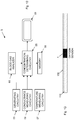
- Fig. 1 is a schematic diagram of an oxygen sensor 1 configured for electrochemical determination of a concentration of dissolved oxygen in a liquid medium according to an embodiment.
- the oxygen sensor 1 comprises a working electrode (WE) configured to be in contact with the liquid medium and a reference electrode (RE) configured to be in contact with the liquid medium.
- the reference electrode has a surface area that is equal to or larger than a surface area of the working electrode.
- at least the surface of the reference electrode is made of Ag/AgCl.
- the oxygen sensor 1 comprises a retaining circuitry 10 configured to temporarily retain a floating voltage between the working electrode and the reference electrode.
- a measurement voltage circuitry 11 of the oxygen sensor 1 comprises a voltage source configured to apply a measurement voltage between the working electrode and the reference electrode during a first measurement period. The applied measurement voltage causes dissolved oxygen in the liquid medium to react by reduction at a surface of the working electrode to produce an evoked current into the working electrode.
- the oxygen sensor 1 also comprises a floating voltage circuitry 12 configured to apply a voltage between the working electrode and the reference electrode equal to the temporarily retained floating voltage during a second measurement period immediately following and of an equal duration as the first measurement period. This applied voltage produces a current out from the working electrode.
- the oxygen sensor 1 further comprises a generating circuitry 13 configured to generate a signal representative of the concentration of dissolved oxygen in the liquid medium based on a measured net charge to the working electrode equal to a sum of a charge transferred to the working electrode during at least a last part of the first measurement period and a charge transferred to the working electrode during at least a last part of the second measurement period.
- a generating circuitry 13 configured to generate a signal representative of the concentration of dissolved oxygen in the liquid medium based on a measured net charge to the working electrode equal to a sum of a charge transferred to the working electrode during at least a last part of the first measurement period and a charge transferred to the working electrode during at least a last part of the second measurement period.
- the oxygen sensor 1 thereby utilizes a double potential step technique with comparatively long unloaded periods between measurement cycles, i.e., the first measurement period and the second measurement period. This reduces the load on the working and reference electrodes, which in turn increases the longevity of the electrodes and reduces any material transport from the electrodes.
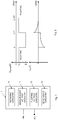
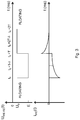
- Fig. 2 are voltage and current versus time diagrams for an oxygen sensor according to an embodiment. The upper part of Fig. 2 illustrates the working electrode potential in relation to the reference electrode (U WE-RE (t)) prior to, during and following the potential steps. The lower part of Fig. 2 illustrates the evoked electrical current (i WE (t)).
- the measurement cycle consists of two phases or periods of equal duration T.
- a floating voltage is the potential of the working electrode as related to the reference electrode that the working electrode will acquire when placed in the liquid medium and no current is allowed to pass through the working electrode.
- This floating voltage or potential is denoted Uo in Fig. 2 .
- the floating voltage is temporarily retained or memorized by the retaining circuitry 10. Then, at the start of the first measurement period, the measurement voltage circuitry 11 applies the measurement voltage E between the working electrode and the reference electrode.
- the measurement voltage circuitry 11 applies the measurement voltage E between the working electrode and the reference electrode.
- the voltage between the working electrode and the reference electrode is impressed to a sufficient negative voltage E to cause oxygen dissolved in the liquid medium to react by reduction at the surface of the working electrode. Accordingly, oxygen molecules are consumed at the working electrode and a concentration gradient of oxygen will arise. Hydroxide ions are created in the reduction reaction and will migrate towards the reference electrode acting as anode.
- the floating voltage circuitry 12 applies the voltage equal to the temporarily retained floating voltage between the working electrode and the reference electrode during the second measurement period immediately following and of equal duration as the first measurement period.
- the evoked current shown in Fig. 2 and floating into the working electrode during the first measurement period contains a contribution that relates to the oxygen concentration and a contribution that relates to charging of the double layer capacitance as mentioned above.
- the current during the second measurement period floats out from the working electrode and relates only to the double layer charging. Accordingly, when merging the currents to each other only the current related to oxygen concentration remains.
- the net charge Q to the working electrode as measured by the generating circuitry 13 is the sum of charge transferred to the working electrode during at least the last parts of the first and second measurement periods. This net charge thereby represents and is indicative of the concentration of dissolved oxygen in the liquid medium.
- the voltage between the working electrode and the reference electrode is floating. At high oxygen tension this voltage returns faster to a voltage closer to zero than at low oxygen tension. This is caused by the amount of oxygen (O 2 ) molecules in the diffusion layer close to the surface of the working electrode.
- O 2 oxygen
- the amplitude of the potential steps is higher than at low oxygen tension, which magnifies the sensitivity of the oxygen sensor.
- the influence of charging the double layer capacitance will also alter, but this effect is eliminated by having double potential steps with equal magnitude but opposite direction and signs.
- the surface of the working electrode is made of a conductive material selected from a group consisting of gold, silver and carbon.
- the surface of the working electrode could be made of conductive pyrolityic glassy carbon or graphene as illustrative, but non-limiting, examples.
- a preferred conductive material is gold.
- At least the surface of the working electrode is made of an inert conductive material.
- Inert means that the surface material of the working electrode should not be oxidizing or changing its properties at the electrochemical use intended in the oxygen sensor.
- the inert conductive material should be stable as long as the potential is kept within potentials described herein, i.e. the floating voltage Uo and the measurement voltage E.
- the surface of the reference electrode is made of Ag/AgCl, i.e., Ag and/or AgCI.
- This conductive material is capable of resisting the anodic load that the reference electrode is exposed to during operation and maintains a stable potential at the intended use.
- the average load of the reference electrode will typically not be zero. In clear contrast, there will be a small anodic net current. Accordingly, a small amount of silver will be consumed on the surface by producing silver chloride; Ag(s) + Cl - ⁇ AgCl + e - .
- This Ag/AgCl layer stabilizes the potential of the reference electrode to about 0.2 V vs. a standard hydrogen electrode (SHE).
- SHE standard hydrogen electrode
- Some AgCI will dissolve slowly into the liquid medium but new AgCI will continuously be produced by the net current load.
- the surface of the reference electrode reacts electrochemically with the liquid medium containing chloride ions (Cl - ) by release of silver ions (Ag + ) from the electrode surface, thereby continuously forming AgCI during use.
- the electrodes do not need to be solid gold, silver or carbon material or solid Ag/AgCI material. This means that the active surface layer of gold, silver or carbon, or of Ag/AgCI could be deposited onto another suitable conductive material.
- the working electrode is made of the conductive material selected from the group consisting of gold, silver and carbon, preferably gold.
- the working electrode is made as a unitary structure of the selected conductive material.
- the working electrode is made of conductive base or bulk material and has a surface layer, such as film or coating, deposited onto the conductive base or bulk material.
- the surface layer is made of a conductive material selected from the group consisting of gold, silver and carbon.
- the conductive base or bulk material could then be made of a non-catalytic material, such as platinum or stainless steel.
- the reference electrode is made of Ag/AgCl.
- the reference electrode is made as a unitary structure of Ag/AgCl.
- the reference electrode is made of conductive base or bulk material and has a surface layer, such as film or coating, deposited onto the conductive base or bulk material.
- the surface layer is made of Ag/AgCl.
- the conductive base or bulk material could then be made of a non-catalytic material, such as platinum, gold, or stainless steel.
- the surface area of the reference electrode is equal to or larger than the surface area of the working electrode.
- the surface area of the reference electrode is larger than the surface area of the working electrode.
- a relationship or ratio of the surface area of the working electrode and the surface area of the reference electrode is within an interval of from 1:1 to 1:100, preferably within an interval of from 1:1.5 to 1:10, more preferably within an interval of from 1:2 to 1:5, such as equal to 1:2.5.
- the potential change from the floating potential Uo is minimized during excitation, i.e., during the first measurement period.
- the surface area of the reference electrodes is comparatively small, the voltage drop over the electrochemical interface at the reference electrode will be large. This in turn implies that the voltage drop at the working electrode will be reduced with the same voltage.
- the reduction potential at the working electrode is preferably in the interval of 0.6 to 1.4 V. Having a larger surface area of the reference electrode as compared to the surface area of the working electrode means that the voltage drop at the reference electrode can be assumed to be at least close to zero.
- the measurement voltage has to be increased beyond the preferred interval.
- the voltage drop at the reference electrode will not be stable and the cross-sensitivity for, among others, temperature and salts in the liquid medium as well as oxidation reactions will be more dominant in the measured net charge.
- having a larger surface area of the reference electrode as compared to the surface area of the working electrode implies that a smaller potential step can be used in the first measurement period, which in turn reduces the influence of other factors, such as temperature and salt concentration in the liquid medium, to the measured net charge.
- the accuracy in the determination of the concentration of dissolved oxygen is increased by having a larger surface area of the reference electrode.
- the larger surface area of the reference electrode as compared to the surface area of the working electrode could be achieved by having larger dimensions of the reference electrode as compared to the working electrode, such as diameter, length, height, etc. depending on the shapes of the reference and working electrodes.
- An alternative, or additional, way of increasing the surface area of the reference electrode is to have a surface that has a surface roughness (R a ) that is larger than a surface roughness of the surface of the working electrode.
- the increase in surface roughness can, for instance, be accomplished by blasting, such as sand blasting, the Ag surface of the reference electrode, i.e., before application of AgCI to form the Ag/AgCI surface.
- the surface of the working electrode is preferably polished to very smooth, i.e., have a low surface roughness.
- Increased surface area of the reference electrode could also, or alternatively, be accomplished by having a porous surface layer.
- the first and second measurement periods are of equal duration and this duration is selected within an interval of from 5 to 20 ms, preferably within an interval of from 7 to 15 ms, and more preferably equal to 10 ms.
- the durations of the first and second measurement periods are quite short with comparatively longer unloaded periods between the measurement occasions. This reduces the load of the electrodes, reduces the material transport at the electrode surfaces and thereby increases the longevity of the electrodes and thereby of the oxygen sensor.
- the sampling period i.e., the duration between measurement occasions, is dependent on the application of the oxygen sensor. However, in most applications the sampling period is at least 50 times, typically at least 100 times, such as several 100 times or even 1000 times, longer as compared to the duration of the first and second measurement periods, i.e., at least 50 ⁇ T. For instance, the sampling period could be within an interval of from 0.5 to 60 s, such as within an interval of from 0.5 to 30 s, for instance within an interval of from 0.5 to 10 s, such as 1 s.
- the measurement voltage circuitry 11 comprises a constant voltage source configured to output a constant voltage, i.e., the measurement voltage E between the working electrode and the reference electrode, during the first measurement period.
- the measurement voltage circuitry 11 is configured to apply a measurement voltage within an interval of from -0.5 to -1.4 V between the working electrode and the reference electrode during the first measurement period.
- Other preferred intervals for the measurement voltage include from -0.5 to -1.2 V or from -0.6 to -1.4 V.
- An example of a suitable measurement voltage is -0.8 V, another suitable measurement voltage is -0.6 V, but also other voltages within the above mentioned interval could be used such as -0.5 V, -0.6 V, -0.7 V, -0.9 V, -1.0 V, -1.1 V, -1.2 V, -1.3 V or -1.4 V.
- the reduction of oxygen takes place at +0.4 V.
- the potential for the Ag/AgCI reference electrode is +0.2 V vs. SHE. In theory, this means that the reduction of O 2 would be possible already from +0.2 V vs. Ag/AgCl.
- the charge transport starts from zero at about -0.5 V and increases linearly with more negative potentials.
- the highest O 2 sensitivity is typically at or around -0.8 V vs. Ag/AgCl. This has several causes, among others, that the diffusion rate of O 2 increases at higher O 2 concentration gradients, the charge transfer increases at higher electrode potentials according Butler-Volmer equation and the migration of ions increases at higher voltages.
- the generating circuitry 13 is configured to generate the signal representative of the concentration of dissolved oxygen in the liquid medium based on a measured net charge to the working electrode equal to a sum of a charge transferred to the working electrode during the first measurement period and a charge transferred to the working electrode during the second measurement period.
- the measured net charge is equal to the sum of the charge transferred to the working electrode during the whole first measurement period and the whole second measurement period.
- the generating circuitry 13 is configured to generate the signal representative of the concentration of dissolved oxygen in the liquid medium based on a measured net charge to the working electrode equal to a sum of a charge transferred to the working electrode during the last part of the first measurement period and a charge transferred to the working electrode during the last part of the second measurement period.
- a reason for merely measuring or calculating the charge transferred to the working electrode during the last parts of the first and second measurement periods is to avoid the initial current peaks that may occur due to limitations in the electronics of the oxygen sensor.
- the duration ⁇ of the last parts of the first and second measurement periods is preferably within an interval of from 0.1T to 0.75T, preferably equal to 0.5T, wherein T denotes the duration of the first and second measurement periods.
- the net charge to the working electrode is, in an embodiment, the sum of the integrated charges at the first and second measurement periods, or the last parts thereof.
- the integrated charge includes both the current related to the reduction of oxygen at the working electrode and the current relating to charging the double layer capacitance.
- the integrated charge that has the opposite sign only relates to the double layer charging.
- the net charge, i.e., the sum of charges is, thus, proportional to the concentration of dissolved oxygen in the liquid medium.
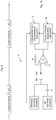
- Fig. 4 is a schematic diagram of an oxygen sensor according to an implementation example.
- the retaining circuitry 20 of the oxygen sensor 2 comprises a voltage follower E2, in the form of an operational amplifier, having a non-inverting input connected to the reference electrode RE and an output connected to an inverting input of the voltage follower E2.
- the retaining circuitry 20 also comprises a switch S3 and a capacitor C1 connected between common ground and the switch S3.
- the switch S3 is connected between the capacitor C1 and the inverting input of the voltage follower E2.
- the retaining circuitry 20 also comprises a resistor R6 connected between the switch S3 and the output of the voltage follower E2.
- the resistor R6 may, alternatively, be connected between the switch S3 and the capacitor C1.
- the resistor R6 and the capacitor C1 form a low pass filter, such as a low pass anti-aliasing filter.
- This optional low pass filter is arranged to reduce noise and has a cut off frequency well below 50 Hz. For instance, if the resistor R6 has a resistance of 330 k ⁇ and the capacitor C1 has a capacitance of 100 nF, the cut off frequency of the low pass filter will be 5 Hz.
- the measurement voltage circuitry 21 and the floating voltage circuitry 22 together comprise a first switch S1 and a voltage source VS connected between common ground and the first switch S1.
- the voltage source VS is a constant voltage source.
- the measurement voltage circuitry 21 and the floating voltage circuitry 22 also comprise an operational amplifier E1 having a non-inverting input connected to the first switch S1, an inverting input connected to the reference electrode RE and an output connected to the reference electrode via a second switch S4.
- a third switch S2 is connected between i) a point between the first switch S1 and the non-inverting input of the operational amplifier E1 and ii) the retaining circuitry 20.
- the generating circuitry 23 of the illustrated oxygen sensor 2 comprises a current amplifier E3 having a non-inverting input connected to common ground, an inverting input connected to the working electrode WE and an output connected to a first switch S5.
- a first resistor R1 a so-called feedback resistor R1 is connected between the inverting input of the current amplifier E3 and the output of the current amplifier E3.
- the generating circuitry 23 also comprises a sample-and-hold circuit and a second resistor R2 connected between the first switch S5 and the sample-and-hold circuit.
- This sample-and-hold circuit comprises an operational amplifier E4 having a non-inverting input connected to common ground, an inverting input connected to the second resistor R2 and an output.
- the sample-and-hold circuit also comprises a capacitor C2 connected between the inverting input of the operational amplifier E4 and the output of the operational amplifier E4 and a second switch S6 connected between the inverting input of the operational amplifier E4 and the output of the operational amplifier E4.
- Fig. 5 schematically illustrates states of the switches S1 to S6 in the oxygen sensor 2 illustrated in Fig. 4 prior to, during and after a measurement cycle according to an embodiment.
- 0 indicates that a switch is open and 1 indicates that a switch is closed.
- the floating potential on the reference electrode RE is applied to the non-inverting input of the voltage follower E2.
- the output of the voltage follower E2 is connected to the capacitor C1 via the closed switch S3. Accordingly, the capacitor C1 is charged to the floating voltage between the reference electrode RE and the working electrode WE.
- This floating voltage is temporarily retained in the capacitor C1 when the switch S3 is opened.
- the constant voltage over the capacitor C2 in the sample-and-hold circuit is also present on the output of the operational amplifier E4 in the sample-and-hold circuit. This voltage value corresponds to the previous measurement conducted in a previous measurement cycle.
- Closing switch S4 connects the operational amplifier E1 to the reference electrode RE. Accordingly, the operational amplifier E1 is able to control its output so that the potential on the non-inverting input and the inverting input of the operational amplifier E1 will be the same through negative feedback.
- the reference electrode RE has the same voltage as the voltage source VS and the voltage between the working electrode and the reference electrode will be the measurement voltage.
- the non-inverting input of the operational amplifier E1 is disconnected from the voltage source VS and is instead connected to the capacitor C1, which is charged by the temporarily retained floating voltage.
- the reference electrode RE is controlled by the operational amplifier E1 to apply a voltage equal to the floating voltage between the reference electrode RE and the working electrode WE during the second measurement period.
- the net charge is the sum of charges transferred to the working electrode during the complete first and second measurement periods.
- Fig. 6 schematically illustrates states of the switches S1 to S6 in the oxygen sensor 2 illustrated in Fig. 4 prior to, during and after a measurement cycle according to another embodiment. In this embodiment, the net charge is instead the sum of charges transferred to the working electrode during the last parts of the first and second measurement periods.
- the resulting net charge will in this embodiment be equal to:
- the potential of the working electrode WE is held at 0 V, i.e., common ground, using the current amplifier E3.
- Non-limiting, but illustrative, values of the resistors and capacitors of the oxygen sensor 2 are presented below.
- the capacitance value of the capacitor C1 is not critical since the capacitor C1 is only used to temporarily retain the floating voltage before the first measurement period.
- the capacitance of the capacitor C1 should not be too small so that leakage and switch capacitances affect the voltage.
- the capacitance of capacitor C1 is preferably within an interval of from 10 nF to 10 ⁇ F, such as 100 nF.
- the capacitor C2 integrates the current during at least the last parts of the first and second measurement periods.
- the voltage over the capacitor C2 at the end of the measurement cycle does preferable not exceed 2.5 V in order to be within common analog to digital converter (ADC) ranges.
- ADC analog to digital converter
- An example of the capacitance for the capacitor C2 is 100 nF.
- the capacitance of the capacitor C2 and the resistances of the resistors R1 and R2 are preferably chosen together to meet any requirements of the ADC input range at all currents that can arise with the specified electrode sizes and oxygen concentration ranges.
- the voltage U(E3) is preferably kept below a clipping threshold of 5V.
- the feedback resistor R1 is programmable within an interval of from 1 to 250 k ⁇ .
- the resistance of the resistor R2 is preferably 20 k ⁇ and the capacitance of the capacitor C2 is preferably 100 nF.
- the implementation example shown in Fig. 4 of the oxygen sensor 2 holds the potential of the working electrode at zero and uses analog techniques to temporarily retain the floating voltage or potential on the capacitor C1 and integrates the net current response on the capacitor C2.
- the circuitry of the oxygen sensor can alternatively be implemented at least partly in a digital microcontroller of signal processor as illustrated in Fig. 7 .
- the oxygen sensor 3 comprises a processing circuitry 34, preferably a microcontroller ( ⁇ C).
- the processing circuitry 34 comprises a first analog input A1 IN connected to the retaining circuitry 30 and a second analog input A2 IN connected to the generating circuitry 33.
- the processing circuitry 34 also comprises an analog output A OUT connected to the reference electrode RE.
- the measurement voltage circuitry 31 and the floating voltage circuitry 32 are implemented in the processing circuitry 34.
- the processing circuitry 34 is then configured to apply, on the analog output A OUT , the measurement voltage during the first measurement period and apply the voltage equal to the temporarily retained floating voltage during the second measurement period.
- the retaining circuitry 30 of Fig. 7 comprises a voltage follower E6 comprising a non-inverting input connected to the reference electrode RE, an output connected to the first analog input A1 IN and an inverting input connected to the output of the voltage follower E6.
- the oxygen sensor 3 also comprises a low pass filter, such as a low pass anti-aliasing filter, connected between the retaining circuitry 30 and the first analog input A1 IN .
- the low pass filter is implemented as a resistor R4 connected between the retaining circuitry 30 and the first analog input A1 IN and a capacitor C3 connected between common ground and point between the resistor R4 and the first analog input A1 IN .
- This optional low pass filter is arranged to reduce noise on the first analog input A1 N .
- the low pass filter has a cut off frequency within an interval of from 5 to 20 Hz.
- the capacitor C3 could have a capacitance of 100 nF and the resistor R4 has a resistance of 180 k ⁇ , which gives a limit at 9 Hz that significantly reduces the sensitivity for 50 Hz noise. If present in a 50 Hz noisy environment, the oxygen sensor 3 may otherwise show aliasing behavior without any low pass filter.
- the oxygen sensor 3 comprises a switch S6 connected between the reference electrode RE and the analog output A OUT .
- the processing circuitry 34 preferably comprises a digital output D OUT connected to the switch S6 and configured to output a control signal configured to close the switch S6 during the first measurement period and the second measurement period and otherwise leave the switch S6 opened.
- This optional switch S6 is preferably included if the analog output A OUT does not have a high impedance output mode. This means that the switch S6 can thereby be used to disconnect the reference electrode RE between measurement cycles.
- the generating circuitry 33 comprises a current amplifier E5 comprising a non-inverting input connected to common ground, an inverting input connected to the working electrode WE and an output connected to the second analog input A2 IN .
- the generating circuitry 33 also comprises a resistor R3, a so-called feedback resistor R3, connected between the inverting input of the current amplifier E5 and the output of the current amplifier E5.
- the current amplifier E5 and the feedback resistor R3 in Fig. 7 correspond to the current amplifier E3 and the feedback resistor R1 in Fig. 4 .
- the processing circuitry 34 is, in an embodiment, configured to sample a voltage on the second analog input A2 IN during at least the last part of the first measurement period and at least the last part of the second measurement period and add the sampled voltages to get a value representative of the net charge to the working electrode WE.
- U(pO 2 ) can be calculated using the following equation.
- the feedback resistor R3 in Fig. 7 can have a resistance value as previously described herein in connection with the feedback resistor R1 in Fig. 4 .
- a resistor of fixed resistance of, for instance, 2 k ⁇ can be used if 14 bit or more ADC is used.
- filters can be arranged in the data stream.
- filters can be an averaging filter, such as a finite impulse response (FIR) filter or a Butterworth filter.
- FIR finite impulse response
- Fig. 8 schematically illustrates signals on the inputs and outputs of the microcontroller shown in Fig. 7 prior to, during and after a measurement cycle according to an embodiment.
- the voltage on the second analog input A2 IN is proportional to the charge transport or electrical current to the working electrode WE.
- the summary of the samples between t 0 and t 0 + 2T will then be linearly dependent on the oxygen tension (pO 2 ), i.e., the concentration of dissolved oxygen in the liquid medium.
- the summary of the samples from t 0 + T - ⁇ to t 0 + T and t 0 + 2T - ⁇ to t 0 + 2T will linearly dependent on the concentration of dissolved oxygen in the liquid medium.
- the oxygen sensor 4, 5, see Figs. 10 and 12 also comprises a concentration determining circuitry 45, 55.
- This concentration determining circuitry 45, 55 is configured to determine a value of the concentration of dissolved oxygen in the liquid medium based on the signal generated based on the measured net charge to the working electrode and a conversion function defining a conversion of a net charge value into a concentration value.
- the value of the concentration of dissolved oxygen is, in an embodiment, expressed as oxygen tension or partial pressure of oxygen (pO 2 ).
- the conversion function such as the values of the parameters k and m, is determined in a calibration procedure.
- a calibration procedure involves measuring the concentration of dissolved oxygen in a liquid medium using an oxygen sensor of the embodiments and using, for instance, a blood gas analyzer at different oxygen concentrations (oxygen tensions).
- the calibration function can be determined given the measured oxygen tension values from the blood gas analyzer and the measured net charge values from the oxygen sensor.
- the conductivity of the liquid medium is therefore measured and used to compensate for this voltage drop that otherwise may affect the measurement voltage.
- the variation in conductance is, however, generally small as long as the geometry of the electrodes is fixed and the liquid medium surrounding the electrodes remains fairly constant, i.e., the electrodes are not moved within the liquid medium.
- the oxygen sensor 4, 5, see Figs. 10 and 12 comprises a conductance measuring circuitry 46, 56 connected to the working electrode WE and the reference electrode RE.
- This conductance measuring circuitry 46, 56 is configured to measure a conductance of the liquid medium in between the working electrode WE and the reference electrode RE and generate a conductance value (G) based on the measured conductance.
- the concentration determining circuitry 45, 55 is configured to determine the value of the concentration of dissolved oxygen in the liquid medium based on the signal generated based on the measured net charge to the working electrode, the conversion function and the conductance value.
- pO 2 f(Q, G).
- Measurement of conductance between two electrodes in a liquid medium is, in an embodiment, performed by a synchronous conductance measuring circuitry 46, 56.
- the excitation voltage during conductance measurements is a square wave signal, such as a square wave 4 kHz signal, with an amplitude of, for instance, 5 mV. Also other frequencies and amplitudes can be used for AC conductance detection.
- the square wave signal is AC coupled with a capacitor C, see Fig. 10 , to avoid net currents passing.
- the electrical current that goes into the working electrode WE is converted to a voltage and demodulated with a detecting circuit synchronous and in phase with the excitation voltage.
- the conductance is the inverse of the impedance, which similarly can be used to compensate the measured net charge for varying conductance or impedance between the working electrode WE and the reference electrode RE.
- Fig. 11 is a schematic block diagram of a synchronous conductance measuring circuitry according to an embodiment, see also Fig. 10 .
- the conductance measurement circuitry 46 comprises an AC voltage source AC VS connected to the reference electrode RE optionally via a coupling capacitor C4, C.
- the conductance measurement circuitry 46 also comprises a current amplifier E7, E having a non-inverting input connected to common ground, an inverting input connected to the working electrode WE and an output.
- a resistor R5, R of the conductance measurement circuitry 46 is connected in parallel between the inverting input of the current amplifier E7, E and the output of the current amplifier E7, E.
- the conductance measurement circuitry further comprises a switch S7, a first amplifier E8 connected between the output of the current amplifier E7 and the switch S7 and a second amplifier E9 connected between the output of the current amplifier E7 and the switch S7.
- the first amplifier E8 and the second amplifier E9 have equal gain.
- the first amplifier E8 is non-inverting and the second amplifier E9 is inverting.
- the switch S7 is configured to switch between an output of the first amplifier E8 and an output of the second amplifier E9 in synchrony with an AC voltage of the AC voltage source AC VS.
- a small defined AC voltage is delivered to the reference electrode RE via a coupling capacitor C4.
- the current response is detected on the current amplifier E7 and amplified further by the first and second amplifiers E8, E9 that have the same gain but the first amplifier E8 is non-inverting while the second amplifier E9 is inverting the signal.
- the switch S7 is switching the signal synchronously with the excitation voltage.
- the signal is also low pass filtered in a low pass filter (LPF) and optionally amplified further in an amplifier E10.
- LPF low pass filter
- the conductance measurement circuitry optionally comprises a second switch S8 connected between the coupling capacitor C4 and the AC voltage source AC VS to disconnect the reference electrode RE from the AC voltage source AC VS between conductance measurement cycles.
- An optional amplifier E11 such as 1:1000, may be arranged between the coupling capacitor C4 or the second switch S8 and the AC voltage source AC VS.
- Fig. 9 schematically illustrates measurement of oxygen concentration (pO 2 ) and conductance, which are separated in time so that the excitation voltages for the pO 2 measurements and the conductance measurement do not interfere with each other.
- the square wave excitation voltage signal is turned off and when the conductance of the liquid medium is measured, no measurement voltages or voltages equal to the floating voltages are applied between the working and reference electrodes.
- the same current amplifier i.e., current-to-voltage converter
- the same current amplifier i.e., current-to-voltage converter
- Temperature changes in the liquid medium may affect the concentration of oxygen as measured using the oxygen sensor. Such temperature dependencies have serval causes.
- the potential of the reference electrode is dependent on the temperature according to Nernst equation.
- the conductivity is temperature dependent. Generally, the conductivity of a liquid medium increases with temperature as the mobility of ions in the liquid medium increases. The relation is, however, quite complex for complex liquid media, such as blood. Also the diffusion of oxygen molecules towards the working electrode is more rapid at increased temperatures.
- oxygen concentration measurements using an oxygen sensor of the embodiments can be performed in a selected liquid medium, such as blood, at different temperatures.
- a selected liquid medium such as blood
- the relationship between the measured net charges and the temperature can be determined. This determined relation can then be used to compensate the measured net charge value for temperature variations if the temperature of the liquid medium is known.
- the oxygen sensor 5 comprises a temperature measuring circuitry 57 configured to measure a temperature of the liquid medium.
- the temperature measuring circuitry 57 is also configured to generate a temperature value based on the measured temperature.
- the concentration determining circuitry 55 is configured to determine the value of the concentration of dissolved oxygen in the liquid medium based on the signal generated based on the measured net charge to the working electrode, the conversion function and the temperature value.
- pO 2 f(Q, temperature).
- Fig. 12 is a schematic block diagram of an oxygen sensor 5 according to a further embodiment.
- the concentration determining circuitry 55 receives inputs from various circuitries of the oxygen sensor 5 and optionally external devices. For instance, the generating circuitry 55 outputs the signal generated based on the measured net charge to the working electrode, the conductance measuring circuitry 56 outputs the conductance value and the temperature measuring circuitry 57 outputs the temperature value.
- the concentration determining circuitry 55 optionally also receives blood gas reference data from a blood gas analyzer 60 in order to determine the conversion function. Alternatively, such reference data may have previously been determined and stored in a memory or storage 58 accessible to the concentration determining circuitry 55. This memory 58 may, for instance, contain the previously mentioned conversion function or the parameters of the conversion function to be used when determining the concentration of dissolved oxygen based in the received input values.
- a monitor or screen 59 of or connected to the concentration determining circuitry 55 is configured to display the determined concentration value, such as in the form of an oxygen tension or partial pressure pO 2 value.
- a coulometric oxygen sensor 53 could be used in connection with a conductance sensor 56 and a temperature sensor 57.
- the timing of the oxygen and conductance measurements is controlled with a microcontroller, which also converts analog signals from the sensors to digital data that may be transferred to a computer or tablet, in which at least the concentration determining circuitry 55 may be implemented in an embodiment.
- a software algorithm post-processes the data in order to compensate the net charge for varying conductance and/or temperature.
- pO 2 reference data from a blood gas analyzer 60 is used as target reference value to the algorithm for calculation of pO 2 from the raw signal.
- the oxygen sensor After insertion into a blood vessel, the oxygen sensor is optionally regularly calibrated according to a known relation between oxygen tension and measured net charge.
- a synchronous conductance sensor can be included between the working and reference electrodes.
- a 4 kHz square wave voltage with the amplitude of a few millivolts is used for excitation between the oxygen measurements.
- the excitation voltage is AC coupled via a capacitor and the current to the working electrode is preferably measured using the same amplifier as for the oxygen measurements.
- An aspect of the embodiments also relates to a catheter 100 comprising an oxygen sensor 1 according to any of the embodiments, see Fig. 13 .
- the complete oxygen sensor 1 is arranged in the catheter 100.
- a monitoring system 140 comprises a catheter 100 comprising the working electrode WE and the reference electrode RE of an oxygen sensor according to any of the embodiments.
- the monitoring system 140 also comprises a processing device 120 connected to the catheter 100 and comprising the retaining circuitry, the measurement voltage circuitry, the floating voltage circuitry and the generating circuitry of the oxygen sensor.
- electrodes of the oxygen sensor are arranged in the catheter 100, whereas the circuitries of the oxygen sensor are instead in implemented in the processing device 120.
- the catheter 100 may also comprise a temperature sensor, such as thermistor or thermocouple TE, used by a temperature measuring circuitry of the oxygen sensor to measure the temperature of the liquid medium.
- a temperature sensor such as thermistor or thermocouple TE
- the oxygen sensor comprises the previously mentioned conductance measuring circuitry and/or the temperature measuring circuitry these are preferably also implemented in the processing device 120.
- the oxygen concentration data is preferably transferred to a monitor 130 via a cable or wireless from the processing device 120, but a user interface can also be used to manually input the reference pO 2 data after taking blood samples.
- Pulse oximeter data may also be displayed on the monitor 130 as safety feature for comparison of measured SpO 2 and calculated pO 2 values. If unlikely big discrepancies would occur a warning can be displayed on the monitor 130.
- the analyzed liquid medium where the oxygen is measured should be a salty solution that contains chloride ions (Cl - ), e.g., blood, cerebrospinal fluid or saline solutions.
- a catheter 100 with electrodes and sensors is placed with the distal end in the liquid medium, such as body fluid.
- the proximal end of the catheter 100 is connected to the processing device 120, which controls the circuitries of the oxygen sensor and processes measured data. Digital data is then transferred, with wire or wireless, from the processing device 120 to a monitor 130 for display.
- the electrodes of the oxygen sensor may be mounted on a catheter 100 or inside a tube where the electrodes are in contact with the analyzed liquid medium.
- the catheter 100 may then be implanted in a living body, preferably in a blood vessel, or in a tube for ex vivo blood monitoring.
- an umbilical catheter with electrodes may be used.
- the catheter has two ring electrodes for oxygen measurements and optional conductance measurements, see Fig. 15 .
- an electrical connector is used to connect to the processing device 120.
- a Luer connector may be used to draw blood samples.
- the working electrode WE can have a surface area of 0.1 - 5 mm 2 , preferably 2.5 mm 2 and the reference electrode RE has a surface area of 2 - 15 mm 2 , preferable 10 mm 2 , with the proviso that the surface area of the reference electrode RE is larger than the surface area of the working electrode WE.
- the surface area of the reference electrode is 1.5-10 times larger than the surface area of the working electrode WE.
- the distance between the electrodes is in the embodiment 4 -100 mm.
- the catheter 100 contains a through lumen 110 and a Luer connector in the proximal end to enable taking blood samples for analysis, infuse nutrition and medications, and to measure blood pressure.
- the catheter body can also contain a thermistor or temperature sensor TE for temperature monitoring as well as input to the algorithm for compensation for temperature dependency of the oxygen sensor.
- blood samples via the Luer connector on the catheter when the oxygen sensor is placed in the blood vessel.
- These blood samples may be analyzed in a blood gas analyzer and the measured pO 2 value, hematocrit and other blood status can be used as input to recalibrate the oxygen sensor.
- the blood cell density has an influence on the diffusion of oxygen molecules to the working electrode surface and the red blood cells will additionally buffer the oxygen level in the diffusion layer these aspects could be considered in a calibration against blood samples.
- a conversion function that from a given measured net charge value calculates the oxygen tension in, for instance, kPa may contain inputs from a plurality of blood gas parameters including pO 2 , Hb or hematocrit, temperature, Cl - , etc.
- the cycling of the working electrode potential according to the embodiments has an advantage to the oxygen sensor.
- Novel electrodes are known to lose their activity towards oxygen reduction when operated continuously over extended periods of time.
- interference can arise from heavy metal traces, which poison the cathode, i.e., the working electrode, by electroplating at the potential where oxygen is reduced.
- a reconditioning procedure is therefore desirable to maintain a stable response.
- the working electrode is reconditioned electrochemically by applying the double voltage waveform.
- the waveform consists of a step during which the current for the reduction of dissolved oxygen is recorded and of another step that reconditions the WE electrode surface. Also when the conductance measurement is performed using a 4 kHz square wave a small reconditioning effect occurs.
- oxidation of the anode i.e., the reference electrode
- This continuous oxidation in the Cl - ion environment maintains a very thin but important AgCI film, which stabilizes the electrical potential of the reference electrode.
- the potential of the reference electrode will thereby be defined by the equilibrium potential between silver and silver chloride.
- Fig. 19 is a flow chart illustrating a method for electrochemical determination of a concentration of dissolved oxygen in a liquid medium.
- the method comprises temporarily retaining, in step 70, a floating voltage between a working electrode configured to be in contact with the liquid medium and a reference electrode configured to be in contact with the liquid medium and having i) a surface area that is equal to or larger than a surface area of the working electrode, and ii) a surface made of Ag/AgCl.
- the method also comprises applying, in step 71, a measurement voltage between the working electrode and the reference electrode during a first measurement period causing dissolved oxygen in the liquid medium to react by reduction at a surface of the working electrode to produce an evoked current into the working electrode.
- the method further comprises applying, in step 72, a voltage between the working electrode and the reference electrode equal to the temporarily retained floating voltage during a second measurement period immediately following and of an equal duration as the first measurement period to produce a current out from the working electrode.
- the method further comprises generating, in step 73, a signal representative of the concentration of dissolved oxygen in the liquid medium based on a measured net charge to the working electrode equal to a sum of a charge transferred to the working electrode during at least a last part of the first measurement period and a charge transferred to the working electrode during at least a last part of the second measurement period.
- Fig. 20 is a schematic block diagram of a computer program based implementation 200 according to an embodiment.
- a computer program 240 which is loaded into the memory 220 for execution by processing circuitry including one or more processors 210.
- the processor(s) 210 and memory 220 are interconnected to each other to enable normal software execution.
- An optional I/O unit 230 may also be interconnected to the processor(s) 210 and/or the memory 220 to enable input and/or output of relevant data.
- processor' should be interpreted in a general sense as any circuitry, system or device capable of executing program code or computer program instructions to perform a particular processing, determining or computing task.
- the processing circuitry including one or more processors 210 is thus configured to perform, when executing the computer program 240, well-defined processing tasks such as those described herein.
- the processing circuitry does not have to be dedicated to only execute the above-described steps, functions, procedure and/or blocks, but may also execute other tasks.
- the computer program 240 comprises instructions, which when executed by at least one processor 210, cause the at least one processor 210 to temporarily retain a floating voltage between a working electrode configured to be in contact with a liquid medium comprising dissolved oxygen and a reference electrode configured to be in contact with the liquid medium and having i) a surface area that is equal to or larger than a surface area of the working electrode, and ii) a surface made of Ag/AgCl.
- the at least one processor 210 is also caused to control a voltage source to apply a measurement voltage between the working electrode and the reference electrode during a first measurement period causing dissolved oxygen in the liquid medium to react by reduction at a surface of the working electrode to produce an evoked current into the working electrode.
- the at least one processor 210 is further caused to control the voltage source to apply a voltage between the working electrode and the reference electrode equal to the temporarily retained floating voltage during a second measurement period immediately following and of an equal duration as the first measurement period to produce a current out from the working electrode.
- the at least one processor 210 is additionally caused to generate a signal representative of the concentration of dissolved oxygen in the liquid medium based on a measured net charge to the working electrode equal to a sum of a charge transferred to the working electrode during at least a last part of the first measurement period and a charge transferred to the working electrode during at least a last part of the second measurement period.
- the proposed technology also provides a carrier 250 comprising the computer program 240.
- the carrier 250 is one of an electronic signal, an optical signal, an electromagnetic signal, a magnetic signal, an electric signal, a radio signal, a microwave signal, or a computer-readable storage medium.
- the software or computer program 240 may be realized as a computer program product, which is normally carried or stored on a computer-readable medium 250, in particular a non-volatile medium.
- the computer-readable medium may include one or more removable or non-removable memory devices including, but not limited to a Read-Only Memory (ROM), a Random Access Memory (RAM), a Compact Disc (CD), a Digital Versatile Disc (DVD), a Blu-ray disc, a Universal Serial Bus (USB) memory, a Hard Disk Drive (HDD) storage device, a flash memory, a magnetic tape, or any other conventional memory device.
- the computer program 240 may thus be loaded into the operating memory 220 of a device 200 for execution by the processing circuitry 210 thereof.
- An oxygen sensor of the embodiment with gold working electrode and Ag/AgCI reference electrode was tested in vivo using a porcine model.
- the porcine subject was anesthetized and kept in narcosis intravenously during eight hours, while it was artificially ventilated with different gas mixtures of nitrogen and oxygen.
- the net charge Q from an oxygen sensor of the embodiments and blood gas reference data is displayed in Fig. 17 .
- a four hour settling time was observed for the oxygen sensor.
- Fig. 17 indicates the net charge as measured by the oxygen sensor together with pO 2 values as measured by a blood gas analyzer.
- the raw net charge signal was thereafter post-processed by subtracting a settling time component from the raw net charge signal.
- the resulting signal was divided with the normalized conductance value.
- the final pO 2 result is shown in Fig. 18 , which verifies the feasibility of the oxygen sensor.
Landscapes
- Health & Medical Sciences (AREA)
- Life Sciences & Earth Sciences (AREA)
- Engineering & Computer Science (AREA)
- Physics & Mathematics (AREA)
- Chemical & Material Sciences (AREA)
- Biomedical Technology (AREA)
- General Health & Medical Sciences (AREA)
- Molecular Biology (AREA)
- Pathology (AREA)
- Biophysics (AREA)
- Veterinary Medicine (AREA)
- Public Health (AREA)
- Medical Informatics (AREA)
- Heart & Thoracic Surgery (AREA)
- Surgery (AREA)
- Animal Behavior & Ethology (AREA)
- Immunology (AREA)
- Biochemistry (AREA)
- Chemical Kinetics & Catalysis (AREA)
- General Physics & Mathematics (AREA)
- Analytical Chemistry (AREA)
- Hematology (AREA)
- Optics & Photonics (AREA)
- Signal Processing (AREA)
- Electrochemistry (AREA)
- Medicinal Chemistry (AREA)
- Urology & Nephrology (AREA)
- Food Science & Technology (AREA)
- General Chemical & Material Sciences (AREA)
- Ecology (AREA)
- Power Engineering (AREA)
- Artificial Intelligence (AREA)
- Computer Vision & Pattern Recognition (AREA)
- Physiology (AREA)
- Psychiatry (AREA)
- Measurement Of The Respiration, Hearing Ability, Form, And Blood Characteristics Of Living Organisms (AREA)
Applications Claiming Priority (1)
| Application Number | Priority Date | Filing Date | Title |
|---|---|---|---|
| SE1730127 | 2017-05-05 |
Publications (3)
| Publication Number | Publication Date |
|---|---|
| EP3399308A1 true EP3399308A1 (fr) | 2018-11-07 |
| EP3399308B1 EP3399308B1 (fr) | 2023-06-07 |
| EP3399308C0 EP3399308C0 (fr) | 2023-06-07 |
Family
ID=62110937
Family Applications (1)
| Application Number | Title | Priority Date | Filing Date |
|---|---|---|---|
| EP18170476.8A Active EP3399308B1 (fr) | 2017-05-05 | 2018-05-03 | Capteur d'oxygène |
Country Status (2)
| Country | Link |
|---|---|
| US (1) | US11099151B2 (fr) |
| EP (1) | EP3399308B1 (fr) |
Cited By (2)
| Publication number | Priority date | Publication date | Assignee | Title |
|---|---|---|---|---|
| CN112294323A (zh) * | 2019-08-02 | 2021-02-02 | 华广生技股份有限公司 | 微型生物传感器及其测定方法 |
| CN116209898A (zh) * | 2020-07-30 | 2023-06-02 | 加泰罗尼亚生物工程基础研究所 | 用于感测分析反应和生物操作的电化学传感器系统和方法 |
Families Citing this family (5)
| Publication number | Priority date | Publication date | Assignee | Title |
|---|---|---|---|---|
| US10926523B2 (en) * | 2018-06-19 | 2021-02-23 | Sensel, Inc. | Performance enhancement of sensors through surface processing |
| EP3962364A4 (fr) | 2019-05-01 | 2023-08-30 | Bard Access Systems, Inc. | Dispositifs de ponction, systèmes de ponction comprenant ces dispositifs de ponction, et procédés associés |
| US10605642B1 (en) * | 2019-11-27 | 2020-03-31 | Altec Industries, Inc. | Conductive liquid sensing system |
| CN113607791A (zh) * | 2021-08-11 | 2021-11-05 | 上海纳米技术及应用国家工程研究中心有限公司 | 一种罐储泡沫灭火剂霉变预警装置的制备方法及其产品 |
| CN116609490A (zh) * | 2023-06-12 | 2023-08-18 | 深圳市安保医疗科技股份有限公司 | 氧传感器的校准方法、装置、设备及介质 |
Citations (4)
| Publication number | Priority date | Publication date | Assignee | Title |
|---|---|---|---|---|
| US5562815A (en) * | 1994-02-09 | 1996-10-08 | Pacesetter Ab | Apparatus and method for the electrochemical determination of the oxygen concentration of a liquid medium |
| US6236873B1 (en) * | 1996-09-30 | 2001-05-22 | Pacesetter Ab | Electrochemical sensor |
| US6321101B1 (en) * | 1997-10-29 | 2001-11-20 | Pacesetter Ab | Method and device for determination of concentration |
| US20100185252A1 (en) * | 2007-02-28 | 2010-07-22 | Bjoerling Anders | Device and method of a medical implant for monitoring progression of heart failure in a human heart |
Family Cites Families (11)
| Publication number | Priority date | Publication date | Assignee | Title |
|---|---|---|---|---|
| US4198851A (en) * | 1978-05-22 | 1980-04-22 | University Of Utah | Method and structure for detecting the concentration of oxygen in a substance |
| US4269684A (en) | 1979-10-01 | 1981-05-26 | Cordis Corporation | Apparatus for oxygen partial pressure measurement |
| JPS58176539A (ja) * | 1982-04-09 | 1983-10-17 | Matsushita Electric Ind Co Ltd | 血中酸素ガス濃度測定用電極 |
| DE4014109A1 (de) * | 1990-05-02 | 1991-11-07 | Siemens Ag | Elekrochemische bestimmung der sauerstoffkonzentration |
| US6153069A (en) * | 1995-02-09 | 2000-11-28 | Tall Oak Ventures | Apparatus for amperometric Diagnostic analysis |
| SE9703957D0 (sv) * | 1997-10-29 | 1997-10-29 | Pacesetter Ab | Method and device for sensing |
| US6166596A (en) * | 1998-03-31 | 2000-12-26 | Matsushita Electric Industrial Co., Ltd. | High efficiency power amplifying apparatus with phase compensation circuit |
| US7964146B2 (en) * | 2004-05-30 | 2011-06-21 | Agamatrix, Inc. | Measuring device and methods for use therewith |
| US20100010328A1 (en) | 2008-07-11 | 2010-01-14 | Nguyen Harry D | Probes and sensors for ascertaining blood characteristics and methods and devices for use therewith |
| US9351677B2 (en) | 2009-07-02 | 2016-05-31 | Dexcom, Inc. | Analyte sensor with increased reference capacity |
| US20170273610A1 (en) | 2014-03-12 | 2017-09-28 | Glucovation, Inc | Wearable electrochemical sensor and method |
-
2018
- 2018-05-03 EP EP18170476.8A patent/EP3399308B1/fr active Active
- 2018-05-03 US US15/970,008 patent/US11099151B2/en active Active
Patent Citations (4)
| Publication number | Priority date | Publication date | Assignee | Title |
|---|---|---|---|---|
| US5562815A (en) * | 1994-02-09 | 1996-10-08 | Pacesetter Ab | Apparatus and method for the electrochemical determination of the oxygen concentration of a liquid medium |
| US6236873B1 (en) * | 1996-09-30 | 2001-05-22 | Pacesetter Ab | Electrochemical sensor |
| US6321101B1 (en) * | 1997-10-29 | 2001-11-20 | Pacesetter Ab | Method and device for determination of concentration |
| US20100185252A1 (en) * | 2007-02-28 | 2010-07-22 | Bjoerling Anders | Device and method of a medical implant for monitoring progression of heart failure in a human heart |
Cited By (2)
| Publication number | Priority date | Publication date | Assignee | Title |
|---|---|---|---|---|
| CN112294323A (zh) * | 2019-08-02 | 2021-02-02 | 华广生技股份有限公司 | 微型生物传感器及其测定方法 |
| CN116209898A (zh) * | 2020-07-30 | 2023-06-02 | 加泰罗尼亚生物工程基础研究所 | 用于感测分析反应和生物操作的电化学传感器系统和方法 |
Also Published As
| Publication number | Publication date |
|---|---|
| US20180321181A1 (en) | 2018-11-08 |
| EP3399308B1 (fr) | 2023-06-07 |
| EP3399308C0 (fr) | 2023-06-07 |
| US11099151B2 (en) | 2021-08-24 |
Similar Documents
| Publication | Publication Date | Title |
|---|---|---|
| EP3399308B1 (fr) | Capteur d'oxygène | |
| US4805624A (en) | Low-potential electrochemical redox sensors | |
| EP0929805B1 (fr) | Detecteur electrochimique | |
| US20210379370A1 (en) | Devices And Methods For The Mitigation Of Non-Analyte Signal Perturbations Incident Upon Analyte-Selective Sensor | |
| US5376244A (en) | Electrochemical determination of oxygen concentration | |
| US20070299617A1 (en) | Biofouling self-compensating biosensor | |
| JP2007503577A (ja) | 電気化学的特性のアッセイのための方法および装置 | |
| JP2001501515A (ja) | 酸化窒素の電気化学的検出用電極 | |
| CN102414560A (zh) | 分析物传感器偏移标准化 | |
| US20250213859A1 (en) | Devices and methods for the mitigation of non-analyte signal perturbations incident upon analyte-selective sensor | |
| EP4564370A2 (fr) | Dispositif pour l'atténuation d'un signal dérivé d'un non-analyte | |
| KR101730288B1 (ko) | 펄스화된 dc 블록을 갖는 테스트 시퀀스로 분석물질을 전기화학적으로 측정하는 방법들, 및 그것을 통합한 디바이스들, 장치들 및 시스템들 | |
| US5968340A (en) | Polarographic self-referencing probe and method for using | |
| US4798655A (en) | Multiparameter analytical electrode structure and method of measurement | |
| CN115190971A (zh) | 用于确定分析物传感器的至少一种膜特性的方法和系统 | |
| Preidel et al. | A new principle for an electrochemical oxygen sensor | |
| EP2956765A1 (fr) | Système et procédé pour mesurer un analyte dans un échantillon et calculer des concentrations de glucose indépendamment des hématocrites | |
| Zhou et al. | Non-invasive, real-time and dynamic monitoring of CO2 and O2 simultaneously using modulated potential pulse-amperometry/coulometry | |
| Zhou et al. | Studies on the biomedical sensor techniques for real-time and dynamic monitoring of respiratory gases, CO2 and O2 | |
| US20250244285A1 (en) | Circuitry for Measurement of Electrochemical Cells | |
| RU2793144C1 (ru) | Способ для определения концентрации аналита в пробе | |
| Zhou et al. | New approaches for developing transient electrochemical multi-component gas sensors | |
| JP2945082B2 (ja) | 酸素濃度測定装置及び測定方法 | |
| ES2823199T3 (es) | Amperometría de pulsos con lectura rápida | |
| JPS5933389B2 (ja) | ポ−ラログラフイ−センサ− |
Legal Events
| Date | Code | Title | Description |
|---|---|---|---|
| PUAI | Public reference made under article 153(3) epc to a published international application that has entered the european phase |
Free format text: ORIGINAL CODE: 0009012 |
|
| STAA | Information on the status of an ep patent application or granted ep patent |
Free format text: STATUS: THE APPLICATION HAS BEEN PUBLISHED |
|
| AK | Designated contracting states |
Kind code of ref document: A1 Designated state(s): AL AT BE BG CH CY CZ DE DK EE ES FI FR GB GR HR HU IE IS IT LI LT LU LV MC MK MT NL NO PL PT RO RS SE SI SK SM TR |
|
| AX | Request for extension of the european patent |
Extension state: BA ME |
|
| STAA | Information on the status of an ep patent application or granted ep patent |
Free format text: STATUS: REQUEST FOR EXAMINATION WAS MADE |
|
| 17P | Request for examination filed |
Effective date: 20190507 |
|
| RBV | Designated contracting states (corrected) |
Designated state(s): AL AT BE BG CH CY CZ DE DK EE ES FI FR GB GR HR HU IE IS IT LI LT LU LV MC MK MT NL NO PL PT RO RS SE SI SK SM TR |
|
| STAA | Information on the status of an ep patent application or granted ep patent |
Free format text: STATUS: EXAMINATION IS IN PROGRESS |
|
| 17Q | First examination report despatched |
Effective date: 20200129 |
|
| GRAP | Despatch of communication of intention to grant a patent |
Free format text: ORIGINAL CODE: EPIDOSNIGR1 |
|
| STAA | Information on the status of an ep patent application or granted ep patent |
Free format text: STATUS: GRANT OF PATENT IS INTENDED |
|
| GRAS | Grant fee paid |
Free format text: ORIGINAL CODE: EPIDOSNIGR3 |
|
| INTG | Intention to grant announced |
Effective date: 20230131 |
|
| GRAA | (expected) grant |
Free format text: ORIGINAL CODE: 0009210 |
|
| STAA | Information on the status of an ep patent application or granted ep patent |
Free format text: STATUS: THE PATENT HAS BEEN GRANTED |
|
| AK | Designated contracting states |
Kind code of ref document: B1 Designated state(s): AL AT BE BG CH CY CZ DE DK EE ES FI FR GB GR HR HU IE IS IT LI LT LU LV MC MK MT NL NO PL PT RO RS SE SI SK SM TR |
|
| REG | Reference to a national code |
Ref country code: GB Ref legal event code: FG4D |
|
| REG | Reference to a national code |
Ref country code: CH Ref legal event code: EP Ref country code: AT Ref legal event code: REF Ref document number: 1576579 Country of ref document: AT Kind code of ref document: T Effective date: 20230615 |
|
| REG | Reference to a national code |
Ref country code: DE Ref legal event code: R096 Ref document number: 602018050697 Country of ref document: DE |
|
| U01 | Request for unitary effect filed |
Effective date: 20230705 |
|
| U07 | Unitary effect registered |
Designated state(s): AT BE BG DE DK EE FI FR IT LT LU LV MT NL PT SE SI Effective date: 20230714 |
|
| REG | Reference to a national code |
Ref country code: NO Ref legal event code: T2 Effective date: 20230607 |
|
| REG | Reference to a national code |
Ref country code: LT Ref legal event code: MG9D |
|
| PG25 | Lapsed in a contracting state [announced via postgrant information from national office to epo] |
Ref country code: ES Free format text: LAPSE BECAUSE OF FAILURE TO SUBMIT A TRANSLATION OF THE DESCRIPTION OR TO PAY THE FEE WITHIN THE PRESCRIBED TIME-LIMIT Effective date: 20230607 |
|
| PG25 | Lapsed in a contracting state [announced via postgrant information from national office to epo] |
Ref country code: RS Free format text: LAPSE BECAUSE OF FAILURE TO SUBMIT A TRANSLATION OF THE DESCRIPTION OR TO PAY THE FEE WITHIN THE PRESCRIBED TIME-LIMIT Effective date: 20230607 Ref country code: HR Free format text: LAPSE BECAUSE OF FAILURE TO SUBMIT A TRANSLATION OF THE DESCRIPTION OR TO PAY THE FEE WITHIN THE PRESCRIBED TIME-LIMIT Effective date: 20230607 Ref country code: GR Free format text: LAPSE BECAUSE OF FAILURE TO SUBMIT A TRANSLATION OF THE DESCRIPTION OR TO PAY THE FEE WITHIN THE PRESCRIBED TIME-LIMIT Effective date: 20230908 |
|
| PG25 | Lapsed in a contracting state [announced via postgrant information from national office to epo] |
Ref country code: SK Free format text: LAPSE BECAUSE OF FAILURE TO SUBMIT A TRANSLATION OF THE DESCRIPTION OR TO PAY THE FEE WITHIN THE PRESCRIBED TIME-LIMIT Effective date: 20230607 |
|
| PG25 | Lapsed in a contracting state [announced via postgrant information from national office to epo] |
Ref country code: IS Free format text: LAPSE BECAUSE OF FAILURE TO SUBMIT A TRANSLATION OF THE DESCRIPTION OR TO PAY THE FEE WITHIN THE PRESCRIBED TIME-LIMIT Effective date: 20231007 |
|
| PG25 | Lapsed in a contracting state [announced via postgrant information from national office to epo] |
Ref country code: SM Free format text: LAPSE BECAUSE OF FAILURE TO SUBMIT A TRANSLATION OF THE DESCRIPTION OR TO PAY THE FEE WITHIN THE PRESCRIBED TIME-LIMIT Effective date: 20230607 Ref country code: SK Free format text: LAPSE BECAUSE OF FAILURE TO SUBMIT A TRANSLATION OF THE DESCRIPTION OR TO PAY THE FEE WITHIN THE PRESCRIBED TIME-LIMIT Effective date: 20230607 Ref country code: RO Free format text: LAPSE BECAUSE OF FAILURE TO SUBMIT A TRANSLATION OF THE DESCRIPTION OR TO PAY THE FEE WITHIN THE PRESCRIBED TIME-LIMIT Effective date: 20230607 Ref country code: IS Free format text: LAPSE BECAUSE OF FAILURE TO SUBMIT A TRANSLATION OF THE DESCRIPTION OR TO PAY THE FEE WITHIN THE PRESCRIBED TIME-LIMIT Effective date: 20231007 Ref country code: CZ Free format text: LAPSE BECAUSE OF FAILURE TO SUBMIT A TRANSLATION OF THE DESCRIPTION OR TO PAY THE FEE WITHIN THE PRESCRIBED TIME-LIMIT Effective date: 20230607 |
|
| PG25 | Lapsed in a contracting state [announced via postgrant information from national office to epo] |
Ref country code: PL Free format text: LAPSE BECAUSE OF FAILURE TO SUBMIT A TRANSLATION OF THE DESCRIPTION OR TO PAY THE FEE WITHIN THE PRESCRIBED TIME-LIMIT Effective date: 20230607 |
|
| REG | Reference to a national code |
Ref country code: DE Ref legal event code: R097 Ref document number: 602018050697 Country of ref document: DE |
|
| PLBE | No opposition filed within time limit |
Free format text: ORIGINAL CODE: 0009261 |
|
| STAA | Information on the status of an ep patent application or granted ep patent |
Free format text: STATUS: NO OPPOSITION FILED WITHIN TIME LIMIT |
|
| 26N | No opposition filed |
Effective date: 20240308 |
|
| U20 | Renewal fee for the european patent with unitary effect paid |
Year of fee payment: 7 Effective date: 20240507 |
|
| PG25 | Lapsed in a contracting state [announced via postgrant information from national office to epo] |
Ref country code: MC Free format text: LAPSE BECAUSE OF FAILURE TO SUBMIT A TRANSLATION OF THE DESCRIPTION OR TO PAY THE FEE WITHIN THE PRESCRIBED TIME-LIMIT Effective date: 20230607 |
|
| PG25 | Lapsed in a contracting state [announced via postgrant information from national office to epo] |
Ref country code: MC Free format text: LAPSE BECAUSE OF FAILURE TO SUBMIT A TRANSLATION OF THE DESCRIPTION OR TO PAY THE FEE WITHIN THE PRESCRIBED TIME-LIMIT Effective date: 20230607 |
|
| PG25 | Lapsed in a contracting state [announced via postgrant information from national office to epo] |
Ref country code: IE Free format text: LAPSE BECAUSE OF NON-PAYMENT OF DUE FEES Effective date: 20240503 |
|
| U20 | Renewal fee for the european patent with unitary effect paid |
Year of fee payment: 8 Effective date: 20250506 |
|
| PGFP | Annual fee paid to national office [announced via postgrant information from national office to epo] |
Ref country code: GB Payment date: 20250506 Year of fee payment: 8 |
|
| PGFP | Annual fee paid to national office [announced via postgrant information from national office to epo] |
Ref country code: NO Payment date: 20250520 Year of fee payment: 8 |
|
| PGFP | Annual fee paid to national office [announced via postgrant information from national office to epo] |
Ref country code: CH Payment date: 20250601 Year of fee payment: 8 |
|
| PG25 | Lapsed in a contracting state [announced via postgrant information from national office to epo] |
Ref country code: CY Free format text: LAPSE BECAUSE OF FAILURE TO SUBMIT A TRANSLATION OF THE DESCRIPTION OR TO PAY THE FEE WITHIN THE PRESCRIBED TIME-LIMIT; INVALID AB INITIO Effective date: 20180503 |
|
| PG25 | Lapsed in a contracting state [announced via postgrant information from national office to epo] |
Ref country code: HU Free format text: LAPSE BECAUSE OF FAILURE TO SUBMIT A TRANSLATION OF THE DESCRIPTION OR TO PAY THE FEE WITHIN THE PRESCRIBED TIME-LIMIT; INVALID AB INITIO Effective date: 20180503 |