EP3400347B1 - Dispositif de raccord pour éléments traversant la toiture - Google Patents
Dispositif de raccord pour éléments traversant la toiture Download PDFInfo
- Publication number
- EP3400347B1 EP3400347B1 EP17700055.1A EP17700055A EP3400347B1 EP 3400347 B1 EP3400347 B1 EP 3400347B1 EP 17700055 A EP17700055 A EP 17700055A EP 3400347 B1 EP3400347 B1 EP 3400347B1
- Authority
- EP
- European Patent Office
- Prior art keywords
- flange
- pipe
- ring element
- base element
- latching
- Prior art date
- Legal status (The legal status is an assumption and is not a legal conclusion. Google has not performed a legal analysis and makes no representation as to the accuracy of the status listed.)
- Active
Links
Images


Classifications
-
- E—FIXED CONSTRUCTIONS
- E04—BUILDING
- E04D—ROOF COVERINGS; SKY-LIGHTS; GUTTERS; ROOF-WORKING TOOLS
- E04D13/00—Special arrangements or devices in connection with roof coverings; Protection against birds; Roof drainage ; Sky-lights
- E04D13/14—Junctions of roof sheathings to chimneys or other parts extending above the roof
- E04D13/147—Junctions of roof sheathings to chimneys or other parts extending above the roof specially adapted for inclined roofs
- E04D13/1473—Junctions of roof sheathings to chimneys or other parts extending above the roof specially adapted for inclined roofs specially adapted to the cross-section of the parts extending above the roof
- E04D13/1476—Junctions of roof sheathings to chimneys or other parts extending above the roof specially adapted for inclined roofs specially adapted to the cross-section of the parts extending above the roof wherein the parts extending above the roof have a generally circular cross-section
-
- E—FIXED CONSTRUCTIONS
- E04—BUILDING
- E04D—ROOF COVERINGS; SKY-LIGHTS; GUTTERS; ROOF-WORKING TOOLS
- E04D13/00—Special arrangements or devices in connection with roof coverings; Protection against birds; Roof drainage ; Sky-lights
- E04D13/14—Junctions of roof sheathings to chimneys or other parts extending above the roof
- E04D13/1407—Junctions of roof sheathings to chimneys or other parts extending above the roof for flat roofs
Definitions
- the present invention relates to a device for connection of roof penetrations to the respective sub-roof.
- connection of the pipe of a sanitary ventilation and/or room ventilation to the vapour pipe of a passage tile happens generally by cutting an aperture in the sub-roof sheeting, guiding the vapour pipe through the aperture, normally sealing by means of a tape or the like and sliding onto the vapour pipe from below a flexible hose connector for a connection with the ventilation pipe.
- DE 44 30 657 A1 teaches a device for sealing the transition between the lateral surface and a roof-passageway, consisting of a foil collar and a connecting portion to be connected with the sealing foil (roof sub-sheeting) and made from a prefabricated formed component that can be pulled over the pipe with the foil collar.
- the middle portion of the foil is formed as cylindrical ring whose internal diameter corresponds to the outer diameter of the vapour pipe.
- a connector ring that consists of a base element having a first cylindrical pipe section with a flange connecting to the pipe end, and an elastic ring that is pulled onto the pipe and engages in a circumferential groove on the outside of the pipe section.
- the elastic ring can be folded upwards and downwards.
- the connector ring is now first screwed in the cut-out in the sub-roof sheeting, with a folded up ring by means of a slot provided in the flange of the first pipe section, until the flange is situated below the sub-roof sheeting.
- the elastic ring is folded down, such that it rests on the sub-roof sheeting with the underside of its edge, and the sub-roof sheeting is clamped between the flange and the ring.
- the outwardly facing end of the pipe section is sealed with a sealing lid.
- This device enables, due to the flexibility of the ring, a repeated up and down folding. It is, however, disadvantageous that the tightness of the device reduces over time due to weather conditions and in the case of standing water.
- Another device is known from DE 29721602 U1 .
- the object of the present invention is to provide a flexible device for connection of roof passages or penetrations, that maintains its tightness for a long period of time, also with standing water.
- the object is solved by the features of claim 1.
- a device for connection of roof penetrations is provided with a base element comprising a pipe having a flange at its one end and a ring element comprising a pipe with a flange at its one end, wherein the pipe of the ring element encompasses the pipe of the base element and is slidable relative thereto.
- Both flanges are oriented in the same direction and at the lateral surface of the pipe of the base element at least one first latching element and at the internal side of the pipe of the ring element at least one second latching element is provided and by the cooperation of the first latching element with the second latching element a latching connection between the base element and the ring element is achieved, wherein the flange of the base element comprises a radially extending slot.
- the ring element may comprise a circumferential outwardly directed web at its end opposite the flange.
- the ring element may additionally or alternatively comprise a screw thread.
- a sealing lid may be provided. Sealing is to be understood as watertight sealing.
- This sealing lid is adapted to close the end of the pipe of the ring element, which end is opposite to the one end of the a pipe with one end compromises the flange.
- the sealing lid may accommodate the circumferential outwardly oriented web of the ring element, e.g. in a circumferential bag or recess at its underside.
- the sealing lid may comprise an internal thread corresponding to the screw thread at the ring element.
- the sealing lid may comprise at its upper side various circular cutting guides.
- circular sealing webs may be arranged at the underside of the sealing lid.
- the sealing lid may comprise various outwardly oriented ears.
- the length L12 of the pipe of the base element measured in longitudinal direction L is equal or smaller than the length L22 of the sum of the length of the pipe and the length of the web of the ring element.
- the sealing lid is elastic, especially from a thermoplastic elastomer.
- the base element and the ring element may be made of plastic, especially of polypropylene, polyethylene or PVC.
- a lid has several advantages.
- the provision of a lid allows the device according to the invention to be installed while temporarily not being used to provide a roof penetration, still keeping its water tightness.
- the device Once used to allow a piping or alike to penetrate through the device, in particular through the lid while removing a circle out of the lid by using a circular cutting guide, the device may easily be taken out of service or modified to allow a piping with different diameter. Either a new lid is used to close the pipe, hence the device is taken out of service in a watertight way, or a new lid with an opening adapted to the new piping is used to make a new watertight roof penetration.
- the at least one first latching element may be a circumferential groove and the at least one second latching element may be a circumferential protrusion or vice versa.
- the angle ⁇ between the lateral surface of the base element and the surface of the flange in the direction opposed to the flange may be smaller than the angle ⁇ between the lateral surface of the ring element and the surface of the flange in the direction opposite to the flange and the angles ⁇ , ⁇ are obtuse angles.
- the angle ⁇ is preferably between 93° and 140°, preferably between 95 and 120° such as between 100° and 120°. E.g. ⁇ may be between 95° and 105°.
- the angle ⁇ is preferably between 93° and 140°, preferably between 95 and 120° such as between 100° and 120°. E.g. ⁇ may be between 95° and 105°.
- the invention provides that the flange of the base element comprises a radially extending slot.
- the slot is preferably nothing more but a slit in the flange of the base element, such as a slit from the outer edge of the flange up to the interference of the flange and the pipe of the base element. Most preferably, such slit is provided, while except for the width of this slit, all along the radial circumference of the interface between the flange and the pipe, the flange and pipe are continuously interconnected.
- This slot serves to enable the base element to be rotated into a hole made in the underroof, such that the pipe of the base element projects through the hole.
- a hole with diameter approximately the outer diameter of the pipe is provided in the underroof, though which the device according to the invention is to be provided.
- the edge of this hole is inserted in the slot, such that at one side of the slot, the flange is positioned under the underroof, while at the opposite side, the flange is located above the underroof.
- the base element is rotated around its axis in a direction towards the side of the slot where the flange is above the underroof.
- the flange will rotate into the hole, such that gradually the flange becomes positioned under the underroof.
- the whole flange will be positioned under the underroof, while the pipe sticks through the hole in the underroof.
- the width of the slit is preferably less than about 4mm, such as less than 4mm, e.g. less than 3mm, even less than 2.5mm, e.g. less than or equal to 2mm or 1mm.
- the minimum width needed is minor. Just a cut through with about 0 mm width is suitable. Hence the minimum with is more than 0mm, or more than 0.01mm.
- the first latching element and/or the second latching element may comprise an inclined flank and a steep flank.
- the angle between the inclined flank and the steep flank is an acute angle.
- the latching elements may be provided at the upper end of the base element and the ring element and/or in the middle of the pipes or rather at the lower end of the pipes.
- the inventive connector device comprises a base element having a pipe and a flange and a ring element having a pipe and a flange, wherein the pipe of the ring element encompasses the pipe of the base element and is slidable relative thereto and at the lateral surface of the pipe of the base element one first latching element and at the internal side of the pipe of the ring element one second latching element is provided.
- the latching elements During shifting the one latching element now engages with the other latching element, the latching elements cooperate and a latching connection between the base element and the ring element is achieved.
- the device according to the invention with the latching elements has a higher flexibility, since more than two latching elements or more than one latching connection may be provided.
- This has the advantage that the contact pressure of the flange of the ring element on the flange of the base element is selectable and the connector device can thus be used for sub-roof sheetings of different thicknesses.
- the latching elements may be a groove or a correspondingly formed protrusion or elevation.
- the latching connection is not releasable, such that a material weakening due to repeated opening and closing can be avoided.
- the latching connection may also be denoted as snap or click connection.
- the angle ⁇ between the lateral surface and the surface of the flange of the base element in the direction opposed to the flange is smaller than the angle ⁇ between the lateral surface of the ring element and the surface of the flange in the direction opposite to the flange, wherein the angles ⁇ , ⁇ are obtuse angles.
- the tightness may be achieved in that a web is provided, which extends rectangular from the pipe of the ring element and is accommodated in a bag of the sealing lid.
- a liquid-tight connection of the sealing lid via the ring element up to the upper side of the sub-roof sheeting is achieved.
- the tightness in the device according to the invention is achieved via the ring element and not via the base element.
- the ring element comprises a screw thread in the upper section of its outside and the sealing lid a corresponding internal thread, such that a liquid-tight connection is achieved.
- the connector device according to the invention can be used universally for all roof penetrations, not only for the connection of ventilation or vapour pipes, but also for the connection of photovoltaic systems, antenna masts, solar heating systems or gas boilers.
- the sealing lid at its upper side comprises different circular cutting guides. Cutting knifes can be put on the edges of the cutting guides to be able to cut the desired circular aperture for the respective desired pipe diameter in the correct size in the sealing lid in a simple way.
- the sealing lid at its underside comprises circular sealing webs corresponding to the circular cutting guide and only marginally offset outwards with respect to the circular cutting guide, the sealing webs serve for resting on the lateral surface of the pipe, connector, mast, etc., which is inserted in the sealing lid aperture.
- weak circular means may be provided at the sealing lid.
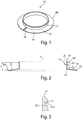
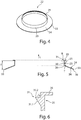
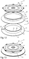
- connection device comprises a base element 12 and a ring element 22 that can be latched or clipped onto the base element 12, see Figure 1 , Figure 4 , Figure 12 .
- the base element 12 consists of a cylindrical pipe 13 that at its one end 16 comprises a flange 14 extending at an obtuse angle ⁇ of 98° with respect to the lateral surface 15 of the pipe 13.
- the flange 14 has a radially extending slot 18. During assembly the edge of the cut-out of the sub-roof sheeting is inserted in this slot 18 and the device is then screwed in the sub-roof sheeting around its longitudinal centre line L as long as the whole flange 14 comes to rest below the sub-roof sheeting.
- a first latching element is located, namely a circumferential groove 19, serving as an engagement of a corresponding second latching element 31 at the ring element 22.
- the groove 19 comprises an inclined flank 19.1 and a steep flank 19.2, the angle between the inclined flank 19.1 and the steep flank 19.2 is an acute angle, see Figure 3 .
- the second latching element namely a rotationally symmetrical circumferential protrusion 31, is provided having an inclined flank 31.1 and a steep flank 31.2.
- the steep flank 31.2 runs at an angle ⁇ of preferably 90° to the longitudinal centre line L of the ring element 22.
- the angle between the inclined flank 31.1 and the steep flank 31.2 is acute and corresponds to the angle between the inclined flank 19.1 and the steep flank 19.2 of the circumferential groove 19 of the base element 12.
- the pipe 23 of the ring element 22 encompasses the pipe 13 of the base element 12, wherein the lateral surface 15 of the base element 12 extends along the internal side 30 of the ring element 22 and the ring element 22 is slidable along the longitudinal centre line L with respect to the base element 12.
- the ring element 22 slides with its internal side 30 along the lateral surface 15 of the base element 12 until the inclined flank 31.1 reaches the inclined surface 20 at the upper end 17 of the base element 12.
- the inclined surface 20 at the end 17 of the base element 12 is curved lightly convexly and ends in the steep flank 19.2 of the groove 19.
- the inclined flank 31.1 slides along the inclined surface 20 of the base element 12, wherein the ring element 22 is lightly pushed outwardly at its upper end 27 until the circumferential protrusion 31 then engages and snaps, respectively, or clips in the groove 19.
- the latching connection between the protrusion 31 and the groove 19 may be releasable or not.
- the ring element 22 once engaged is no longer releasable from the base element 12, i.e. the latching connection is permanent, such that the outer edge 36 of the underside 34 of the flange 24 of the ring element 22 is permanently pressed against the upper side 21 of the flange 14 of the base element 12 under preload.
- the preload is achieved by the angle ⁇ at the base element 12 being smaller than the angle ⁇ at the ring element 22.
- the latching connection 19, 31 the outer lower edge 36 of the flange 24 is pressed against the upper side of the flange 14 of the base element 12.
- the sub-roof sheeting is between the upper side 21 of the flange 12 and the underside 34 of the flange 24, such that a tight connection is achieved.
- a rectangular web 35 extends rectangular to the lateral surface 25 of the pipe 23. This web 35 serves for fastening of a sealing lid 40.
- the sealing lid 40 is preferably made of a thermoplastic elastomer and elastic.
- the base element 12 and the ring element 22 are preferably made of plastic, especially made of polypropylene.
- the stability of the base element 12 is higher than that of the ring element 22, such that the ring element can be slid onto the base element 12 under a slight deformation.
- the sealing lid 40 has the form of a circular disc and at its upper side comprises various circular cutting guides 41, 41.1, 41.2 that indicate different pipe diameters and that serve for guiding of the cutting knife when cutting out the desired circular aperture, if necessary.
- various circular cutting guides 41, 41.1, 41.2 that indicate different pipe diameters and that serve for guiding of the cutting knife when cutting out the desired circular aperture, if necessary.
- an L-shaped web 45 comprising a web section 45.1 running perpendicular to the underside 42 and a web section 45.2 running parallel to the underside 42, such that, between the underside 42 and the web section 45.2, there is a circumferential bag 46 serving for accommodation of the web 35 of the ring element 22.
- the length L12 of the pipe 13 of the base element 12 is smaller than or at most equal to the whole length L22 of the pipe 23 and the web 35, see Figure 10 .
- the upwardly facing side of the web 35 is above or on the same level as the end 17 of the base element 12, such that no water can get to the base element 12 from the outside.
- the elastic sealing lid 40 is put on the ring element 22 and then radially outwardly pulled over the web 35 of the ring element 22, whereby the web 35 of the ring element 22 slides in the radial circumferential bag 46.
- the sealing lid 40 comprises various outwardly protruding ears 47, by means of which the sealing lid 40 can be easier grasped and pulled over the ring element 22.
- a circular cut-out preferably by means of a template, is cut into the sub-roof sheeting. Then the edge of the cut-out of the sub-roof sheeting is put in the slot 18 in the flange 14 of the base element 12 and the device is then screwed in the sheeting until the sub-roof sheeting is above the flange 14.
- the ring element 22 that is slidable on the base element 12 is slid downward until the circumferential groove 31 engages the circumferential groove 19 running at the internal side of the pipe 13.
- the outer edge 36 at the underside 34 of the flange 24 of the ring element 22 is simultaneously pressed from above onto the upper side of the sub-roof sheeting, such that a tight connection is achieved.
- the sealing lid 40 is put on the ring element 22 and the sealing lid 40 is pulled over the horizontal circumferential web 35 at the upper end 27 of the ring element 22 by pulling on the ears 47, such that the web 35 slides in the bag 46 in the sealing lid 40.
- the device according to the invention can be used for roof passages of different diameters and different pipe diameters.
- the device according to the invention cannot only be put and mounted on the sub-roof sheeting from the outside, but in principle also from the top floor through the sub-roof sheeting outwardly.
- the aperture for the pipe is preferably cut into the sealing lid before an assembly, but the cut is also possible after the assembly.
- the arrangement of the grooves/protrusions is inverse.
- the circumferential groove 19 is not arranged at the base element 12, but at the ring element 22, at the point where in the embodiment described above the circumferential protrusion 31 is located, and the circumferential protrusion 31 is not provided on the ring element 22, but on the base element 12.
- the base element 12 and the ring element 22 comprise multiple latching positions, such that the device can be used with sub-roof sheetings of different thicknesses.
- the base element 12 for example comprises multiple grooves 19 and the ring element 22 a circumferential protrusion 31 (or vice versa), such that the ring element 22 with its protrusion 31 upon depressing engages in the first groove 19, then in the second, etc. until it abuts with its flange 24 on the upper side of the sub-roof sheeting and cannot be further depressed.
- the latching elements 19, 31 can be provided at the upper end of the base element 12 and the ring element 22 as well as in the middle of the pipes 13, 23 or rather at their lower end.
Landscapes
- Engineering & Computer Science (AREA)
- Architecture (AREA)
- Civil Engineering (AREA)
- Structural Engineering (AREA)
- Pipe Accessories (AREA)
- Gasket Seals (AREA)
- Body Structure For Vehicles (AREA)
Claims (15)
- Dispositif destiné à raccorder des passages à travers la toiture, comprenant un élément de base (12) qui comprend un tube (13) pourvu, à son extrémité (16), d'une collerette (14) et un élément annulaire (22) qui comprend un tube (23) pourvu, à son extrémité (26), d'une collerette (24), le tube (23) de l'élément annulaire (22) entourant le tube (13) de l'élément de base (12) et pouvant être déplacé par rapport à celui-ci, et les deux collerettes (14, 24) étant tournées dans la même direction, et au moins un premier élément d'enclenchement (19) étant prévu sur la surface latérale (15) du tube (13) de l'élément de base (12), et au moins un deuxième élément d'enclenchement (31) étant prévu sur la face intérieure (30) du tube (23) de l'élément annulaire (22), et un assemblage à enclenchement étant obtenu entre l'élément de base (12) et l'élément annulaire (22) grâce à l'interaction entre ledit premier élément d'enclenchement (19) et ledit deuxième élément d'enclenchement (31), caractérisé en ce que la collerette (14) de l'élément de base (12) comprend une fente (18) qui s'étend de manière radiale.
- Dispositif selon la revendication 1, caractérisé en ce que l'élément annulaire (22) comprend, sur son extrémité (27) située à l'opposé de la collerette (24), un méplat (35) circonférentiel dirigé vers l'extérieur ou un filet de vissage.
- Dispositif selon la revendication 2, caractérisé en ce qu'il est prévu en outre un couvercle d'étanchéité (40).
- Dispositif selon la revendication 3, caractérisé en ce que le couvercle d'étanchéité (40) abrite dans une poche (46) circonférentielle située sur sa face inférieure (42) le méplat (35) circonférentiel, dirigé vers l'extérieur, de l'élément annulaire (22) ou comprend un filetage intérieur qui correspond au filet de vissage situé sur l'élément annulaire (22).
- Dispositif selon l'une quelconque des revendications 3 à 4, caractérisé en ce que le couvercle d'étanchéité (40) comprend, sur sa face supérieure, différents guides de coupe (41) de forme circulaire.
- Dispositif selon l'une quelconque des revendications 3 à 5, caractérisé en ce que des joints d'étanchéité (43) de forme circulaire sont disposés sur la face inférieure (42) du couvercle d'étanchéité (40).
- Dispositif selon l'une quelconque des revendications 2 à 6, caractérisé en ce que la longueur L12 du tube (13) de l'élément de base (12) mesurée en sens longitudinal L est égale ou inférieure à la longueur L22 correspondant à la somme de la longueur du tube (23) et de la longueur du méplat (35) de l'élément annulaire (22).
- Dispositif selon l'une quelconque des revendications 3 à 7, caractérisé en ce que le couvercle d'étanchéité (40) est élastique, en particulier est réalisé en un élastomère thermoplastique.
- Dispositif selon l'une quelconque des revendications 3 à 8, caractérisé en ce que le couvercle d'étanchéité (40) comprend plusieurs oreilles (47) tournées vers l'extérieur.
- Dispositif selon l'une quelconque des revendications précédentes, caractérisé en ce que ledit au moins un premier élément d'enclenchement (19) est une rainure circonférentielle et ledit au moins un deuxième élément d'enclenchement (31) est une saillie circonférentielle, ou vice-versa.
- Dispositif selon l'une quelconque des revendications précédentes, caractérisé en ce que l'angle β entre la surface latérale (15) de l'élément de base (12) et la surface de la collerette (14) dans le sens opposé à ladite collerette (14) est inférieur à l'angle γ entre la surface latérale (32) de l'élément annulaire (22) et la surface de la collerette (24) dans le sens opposé à ladite collerette (24), et que les angles β, γ sont des angles obtus.
- Dispositif selon l'une quelconque des revendications précédentes, caractérisé en ce que le premier élément d'enclenchement (19) et/ou le deuxième élément d'enclenchement (31) comprennent un flanc à pente douce (19.1, 31.1) et un flanc à pente raide (19.2, 31.2).
- Dispositif selon la revendication 12, caractérisé en ce que l'angle entre le flanc à pente douce (31.1, 19.1) et le flanc à pente raide (31.2, 19.2) est un angle aigu.
- Dispositif selon l'une quelconque des revendications précédentes, caractérisé en ce que l'élément de base (12) et l'élément annulaire (22) sont en matière plastique, en particulier en polypropylène, polyéthylène ou en PVC.
- Dispositif selon l'une quelconque des revendications précédentes, caractérisé en ce que les éléments d'enclenchement (19, 31) sont prévus à l'extrémité supérieure de l'élément de base (12) et de l'élément annulaire (22) et/ou au centre des tubes (13, 23) ou bien à l'extrémité inférieure desdits tubes (13, 23).
Priority Applications (4)
| Application Number | Priority Date | Filing Date | Title |
|---|---|---|---|
| HRP20211738TT HRP20211738T1 (hr) | 2016-01-05 | 2017-01-04 | Uređaj za povezivanje s uređajima koji prodiru kroz krov |
| SI201730990T SI3400347T1 (sl) | 2016-01-05 | 2017-01-04 | Naprava za povezavo z napravami, ki predrejo streho |
| RS20211386A RS62655B1 (sr) | 2016-01-05 | 2017-01-04 | Uređaj za povezivanje sa uređajima za proboj krova |
| PL17700055T PL3400347T3 (pl) | 2016-01-05 | 2017-01-04 | Urządzenie do łączenia z urządzeniami zagłębianymi w dachu |
Applications Claiming Priority (2)
| Application Number | Priority Date | Filing Date | Title |
|---|---|---|---|
| EP16150125.9A EP3190241A1 (fr) | 2016-01-05 | 2016-01-05 | Dispositif de raccord pour éléments traversant la toiture |
| PCT/EP2017/050128 WO2017118653A1 (fr) | 2016-01-05 | 2017-01-04 | Dispositif de connexion avec dispositifs de pénétration de toit |
Publications (2)
| Publication Number | Publication Date |
|---|---|
| EP3400347A1 EP3400347A1 (fr) | 2018-11-14 |
| EP3400347B1 true EP3400347B1 (fr) | 2021-09-01 |
Family
ID=55072520
Family Applications (2)
| Application Number | Title | Priority Date | Filing Date |
|---|---|---|---|
| EP16150125.9A Withdrawn EP3190241A1 (fr) | 2016-01-05 | 2016-01-05 | Dispositif de raccord pour éléments traversant la toiture |
| EP17700055.1A Active EP3400347B1 (fr) | 2016-01-05 | 2017-01-04 | Dispositif de raccord pour éléments traversant la toiture |
Family Applications Before (1)
| Application Number | Title | Priority Date | Filing Date |
|---|---|---|---|
| EP16150125.9A Withdrawn EP3190241A1 (fr) | 2016-01-05 | 2016-01-05 | Dispositif de raccord pour éléments traversant la toiture |
Country Status (9)
| Country | Link |
|---|---|
| EP (2) | EP3190241A1 (fr) |
| DK (1) | DK3400347T3 (fr) |
| ES (1) | ES2898691T3 (fr) |
| HR (1) | HRP20211738T1 (fr) |
| HU (1) | HUE056806T2 (fr) |
| PL (1) | PL3400347T3 (fr) |
| RS (1) | RS62655B1 (fr) |
| SI (1) | SI3400347T1 (fr) |
| WO (1) | WO2017118653A1 (fr) |
Families Citing this family (1)
| Publication number | Priority date | Publication date | Assignee | Title |
|---|---|---|---|---|
| DE202021004168U1 (de) | 2021-09-01 | 2022-11-28 | Creaton Gmbh | Vorrichtung zum Anschluss bei Dachdurchdringungen |
Family Cites Families (12)
| Publication number | Priority date | Publication date | Assignee | Title |
|---|---|---|---|---|
| DE6903939U (de) * | 1969-02-01 | 1969-05-22 | Dynamit Nobel Ag | Wasserablauf fuer flachdaecher |
| DE2507045A1 (de) * | 1975-02-19 | 1976-09-09 | Dallmer Helmuth Fa | Dacheinlauf |
| US5036636A (en) * | 1987-12-22 | 1991-08-06 | Hasty William E | Multiple size vent-pipe roof flashing |
| US5711536A (en) * | 1994-05-11 | 1998-01-27 | Tuf-Tite, Inc. | Seal component for use in on-site poured concrete or plastic tank or box components of fluid distribution systems |
| DE4430657A1 (de) | 1994-08-29 | 1996-03-07 | Johannes Kloeber | Vorrichtung zur Abdichtung einer Dachdurchführung |
| DE29721602U1 (de) * | 1997-12-06 | 1998-02-19 | Schulte, Günter, 59757 Arnsberg | Dachdurchführung für eine Rohrleitung, insbesondere Lüftungsrohrleitung |
| DE29824547U1 (de) * | 1998-09-05 | 2001-07-26 | Fleck, Oskar, 45711 Datteln | Dach-Entlüftungs-, insbesondere Flachdach-Entlüftungs-Vorrichtung |
| DE19840593B4 (de) * | 1998-09-05 | 2004-02-19 | Oskar Fleck | Vorrichtung zur Herstellung einer Flachdach-Entwässerung |
| US20050150176A1 (en) * | 2003-12-31 | 2005-07-14 | Craig Erekson | Pipe flashing UV shield |
| NL1025877C2 (nl) * | 2004-04-02 | 2005-10-07 | V O F Naadloze Aluminium Goots | Afvoerinrichting voor een goot alsmede een goot voorzien van een dergelijke afvoerinrichting. |
| DK1945982T3 (en) * | 2005-10-27 | 2018-01-15 | Lake Products Ltd | A peripheral sealing bush for elongated objects that pass through a surface or longer than a moving one |
| DE202010005159U1 (de) * | 2010-03-31 | 2010-09-02 | Karl Grumbach Gmbh & Co. Kg | Brandschutzgully-, Lüfter und -Rohrdurchführung für Dach, Decke und Wand |
-
2016
- 2016-01-05 EP EP16150125.9A patent/EP3190241A1/fr not_active Withdrawn
-
2017
- 2017-01-04 PL PL17700055T patent/PL3400347T3/pl unknown
- 2017-01-04 ES ES17700055T patent/ES2898691T3/es active Active
- 2017-01-04 RS RS20211386A patent/RS62655B1/sr unknown
- 2017-01-04 EP EP17700055.1A patent/EP3400347B1/fr active Active
- 2017-01-04 DK DK17700055.1T patent/DK3400347T3/da active
- 2017-01-04 WO PCT/EP2017/050128 patent/WO2017118653A1/fr not_active Ceased
- 2017-01-04 SI SI201730990T patent/SI3400347T1/sl unknown
- 2017-01-04 HR HRP20211738TT patent/HRP20211738T1/hr unknown
- 2017-01-04 HU HUE17700055A patent/HUE056806T2/hu unknown
Also Published As
| Publication number | Publication date |
|---|---|
| SI3400347T1 (sl) | 2022-01-31 |
| HRP20211738T1 (hr) | 2022-02-18 |
| ES2898691T3 (es) | 2022-03-08 |
| EP3400347A1 (fr) | 2018-11-14 |
| DK3400347T3 (da) | 2021-11-08 |
| HUE056806T2 (hu) | 2022-03-28 |
| EP3190241A1 (fr) | 2017-07-12 |
| WO2017118653A1 (fr) | 2017-07-13 |
| RS62655B1 (sr) | 2021-12-31 |
| PL3400347T3 (pl) | 2022-02-14 |
Similar Documents
| Publication | Publication Date | Title |
|---|---|---|
| DK2063163T3 (en) | Sealing collar to the vapor barrier penetrations | |
| JPS5815670B2 (ja) | シ−ル機構 | |
| US8656667B2 (en) | Roofing composition | |
| US8549793B1 (en) | Flashing system | |
| US8479455B2 (en) | Flashing assembly | |
| US4563847A (en) | Universal flashing for roof vent pipes | |
| US20050055889A1 (en) | Roof flashing assembly | |
| US3703194A (en) | Resilient connector | |
| RU202143U1 (ru) | Кровельный фартук для трубы или канала | |
| US11873635B2 (en) | Drain device having an adapter for connecting to a pipe | |
| US20130020796A1 (en) | One-Piece Roof Flashing | |
| US10787804B2 (en) | Weather barrier for a building penetration with a removable collar | |
| US20130231042A1 (en) | Vent plate with weather barrier for an exterior wall | |
| EP3400347B1 (fr) | Dispositif de raccord pour éléments traversant la toiture | |
| US11692355B1 (en) | External vents | |
| JP5224406B2 (ja) | 配管の壁部貫通構造、配管の壁部貫通部材、および壁部への貫通配管固定方法 | |
| US20060179725A1 (en) | Cover secured around a pipe passed through a building for ornamental and leakage-preventing purposes | |
| JP2019190555A (ja) | 接合構造 | |
| US6431972B1 (en) | Multiple plumbing vent apparatus | |
| US20190249438A1 (en) | Metal roof flashing system | |
| EP1881126B1 (fr) | Système de gouttière | |
| DK179199B9 (en) | Pipe Flashing | |
| FI113291B (fi) | Laite ja menetelmä tiivistämiseksi kanavan tai putken katon läpi menevän läpiviennin ympärillä | |
| FI59513C (fi) | Elinstallationsdosa | |
| CA2035037A1 (fr) | Leve-toiture |
Legal Events
| Date | Code | Title | Description |
|---|---|---|---|
| REG | Reference to a national code |
Ref country code: HR Ref legal event code: TUEP Ref document number: P20211738 Country of ref document: HR |
|
| STAA | Information on the status of an ep patent application or granted ep patent |
Free format text: STATUS: UNKNOWN |
|
| STAA | Information on the status of an ep patent application or granted ep patent |
Free format text: STATUS: THE INTERNATIONAL PUBLICATION HAS BEEN MADE |
|
| PUAI | Public reference made under article 153(3) epc to a published international application that has entered the european phase |
Free format text: ORIGINAL CODE: 0009012 |
|
| STAA | Information on the status of an ep patent application or granted ep patent |
Free format text: STATUS: REQUEST FOR EXAMINATION WAS MADE |
|
| 17P | Request for examination filed |
Effective date: 20180629 |
|
| AK | Designated contracting states |
Kind code of ref document: A1 Designated state(s): AL AT BE BG CH CY CZ DE DK EE ES FI FR GB GR HR HU IE IS IT LI LT LU LV MC MK MT NL NO PL PT RO RS SE SI SK SM TR |
|
| AX | Request for extension of the european patent |
Extension state: BA ME |
|
| DAV | Request for validation of the european patent (deleted) | ||
| DAX | Request for extension of the european patent (deleted) | ||
| RAP1 | Party data changed (applicant data changed or rights of an application transferred) |
Owner name: CREATION GMBH |
|
| STAA | Information on the status of an ep patent application or granted ep patent |
Free format text: STATUS: EXAMINATION IS IN PROGRESS |
|
| 17Q | First examination report despatched |
Effective date: 20200210 |
|
| GRAP | Despatch of communication of intention to grant a patent |
Free format text: ORIGINAL CODE: EPIDOSNIGR1 |
|
| STAA | Information on the status of an ep patent application or granted ep patent |
Free format text: STATUS: GRANT OF PATENT IS INTENDED |
|
| INTG | Intention to grant announced |
Effective date: 20210506 |
|
| GRAS | Grant fee paid |
Free format text: ORIGINAL CODE: EPIDOSNIGR3 |
|
| GRAA | (expected) grant |
Free format text: ORIGINAL CODE: 0009210 |
|
| STAA | Information on the status of an ep patent application or granted ep patent |
Free format text: STATUS: THE PATENT HAS BEEN GRANTED |
|
| AK | Designated contracting states |
Kind code of ref document: B1 Designated state(s): AL AT BE BG CH CY CZ DE DK EE ES FI FR GB GR HR HU IE IS IT LI LT LU LV MC MK MT NL NO PL PT RO RS SE SI SK SM TR |
|
| REG | Reference to a national code |
Ref country code: GB Ref legal event code: FG4D |
|
| REG | Reference to a national code |
Ref country code: CH Ref legal event code: EP Ref country code: AT Ref legal event code: REF Ref document number: 1426405 Country of ref document: AT Kind code of ref document: T Effective date: 20210915 |
|
| REG | Reference to a national code |
Ref country code: DE Ref legal event code: R096 Ref document number: 602017045105 Country of ref document: DE |
|
| REG | Reference to a national code |
Ref country code: IE Ref legal event code: FG4D |
|
| REG | Reference to a national code |
Ref country code: NL Ref legal event code: FP |
|
| REG | Reference to a national code |
Ref country code: DK Ref legal event code: T3 Effective date: 20211101 |
|
| REG | Reference to a national code |
Ref country code: LT Ref legal event code: MG9D |
|
| PG25 | Lapsed in a contracting state [announced via postgrant information from national office to epo] |
Ref country code: FI Free format text: LAPSE BECAUSE OF FAILURE TO SUBMIT A TRANSLATION OF THE DESCRIPTION OR TO PAY THE FEE WITHIN THE PRESCRIBED TIME-LIMIT Effective date: 20210901 Ref country code: LT Free format text: LAPSE BECAUSE OF FAILURE TO SUBMIT A TRANSLATION OF THE DESCRIPTION OR TO PAY THE FEE WITHIN THE PRESCRIBED TIME-LIMIT Effective date: 20210901 Ref country code: BG Free format text: LAPSE BECAUSE OF FAILURE TO SUBMIT A TRANSLATION OF THE DESCRIPTION OR TO PAY THE FEE WITHIN THE PRESCRIBED TIME-LIMIT Effective date: 20211201 Ref country code: SE Free format text: LAPSE BECAUSE OF FAILURE TO SUBMIT A TRANSLATION OF THE DESCRIPTION OR TO PAY THE FEE WITHIN THE PRESCRIBED TIME-LIMIT Effective date: 20210901 |
|
| REG | Reference to a national code |
Ref country code: NO Ref legal event code: T2 Effective date: 20210901 |
|
| REG | Reference to a national code |
Ref country code: HR Ref legal event code: ODRP Ref document number: P20211738 Country of ref document: HR Payment date: 20211228 Year of fee payment: 6 |
|
| REG | Reference to a national code |
Ref country code: HR Ref legal event code: T1PR Ref document number: P20211738 Country of ref document: HR |
|
| PG25 | Lapsed in a contracting state [announced via postgrant information from national office to epo] |
Ref country code: LV Free format text: LAPSE BECAUSE OF FAILURE TO SUBMIT A TRANSLATION OF THE DESCRIPTION OR TO PAY THE FEE WITHIN THE PRESCRIBED TIME-LIMIT Effective date: 20210901 Ref country code: GR Free format text: LAPSE BECAUSE OF FAILURE TO SUBMIT A TRANSLATION OF THE DESCRIPTION OR TO PAY THE FEE WITHIN THE PRESCRIBED TIME-LIMIT Effective date: 20211202 |
|
| REG | Reference to a national code |
Ref country code: ES Ref legal event code: FG2A Ref document number: 2898691 Country of ref document: ES Kind code of ref document: T3 Effective date: 20220308 |
|
| REG | Reference to a national code |
Ref country code: HU Ref legal event code: AG4A Ref document number: E056806 Country of ref document: HU |
|
| PG25 | Lapsed in a contracting state [announced via postgrant information from national office to epo] |
Ref country code: IS Free format text: LAPSE BECAUSE OF FAILURE TO SUBMIT A TRANSLATION OF THE DESCRIPTION OR TO PAY THE FEE WITHIN THE PRESCRIBED TIME-LIMIT Effective date: 20220101 Ref country code: SM Free format text: LAPSE BECAUSE OF FAILURE TO SUBMIT A TRANSLATION OF THE DESCRIPTION OR TO PAY THE FEE WITHIN THE PRESCRIBED TIME-LIMIT Effective date: 20210901 Ref country code: SK Free format text: LAPSE BECAUSE OF FAILURE TO SUBMIT A TRANSLATION OF THE DESCRIPTION OR TO PAY THE FEE WITHIN THE PRESCRIBED TIME-LIMIT Effective date: 20210901 Ref country code: RO Free format text: LAPSE BECAUSE OF FAILURE TO SUBMIT A TRANSLATION OF THE DESCRIPTION OR TO PAY THE FEE WITHIN THE PRESCRIBED TIME-LIMIT Effective date: 20210901 Ref country code: PT Free format text: LAPSE BECAUSE OF FAILURE TO SUBMIT A TRANSLATION OF THE DESCRIPTION OR TO PAY THE FEE WITHIN THE PRESCRIBED TIME-LIMIT Effective date: 20220103 Ref country code: EE Free format text: LAPSE BECAUSE OF FAILURE TO SUBMIT A TRANSLATION OF THE DESCRIPTION OR TO PAY THE FEE WITHIN THE PRESCRIBED TIME-LIMIT Effective date: 20210901 Ref country code: AL Free format text: LAPSE BECAUSE OF FAILURE TO SUBMIT A TRANSLATION OF THE DESCRIPTION OR TO PAY THE FEE WITHIN THE PRESCRIBED TIME-LIMIT Effective date: 20210901 |
|
| REG | Reference to a national code |
Ref country code: DE Ref legal event code: R097 Ref document number: 602017045105 Country of ref document: DE |
|
| PLBE | No opposition filed within time limit |
Free format text: ORIGINAL CODE: 0009261 |
|
| STAA | Information on the status of an ep patent application or granted ep patent |
Free format text: STATUS: NO OPPOSITION FILED WITHIN TIME LIMIT |
|
| 26N | No opposition filed |
Effective date: 20220602 |
|
| PG25 | Lapsed in a contracting state [announced via postgrant information from national office to epo] |
Ref country code: MC Free format text: LAPSE BECAUSE OF FAILURE TO SUBMIT A TRANSLATION OF THE DESCRIPTION OR TO PAY THE FEE WITHIN THE PRESCRIBED TIME-LIMIT Effective date: 20210901 |
|
| GBPC | Gb: european patent ceased through non-payment of renewal fee |
Effective date: 20220104 |
|
| PG25 | Lapsed in a contracting state [announced via postgrant information from national office to epo] |
Ref country code: GB Free format text: LAPSE BECAUSE OF NON-PAYMENT OF DUE FEES Effective date: 20220104 |
|
| REG | Reference to a national code |
Ref country code: HR Ref legal event code: ODRP Ref document number: P20211738 Country of ref document: HR Payment date: 20221228 Year of fee payment: 7 |
|
| PG25 | Lapsed in a contracting state [announced via postgrant information from national office to epo] |
Ref country code: IE Free format text: LAPSE BECAUSE OF NON-PAYMENT OF DUE FEES Effective date: 20220104 |
|
| P01 | Opt-out of the competence of the unified patent court (upc) registered |
Effective date: 20230515 |
|
| REG | Reference to a national code |
Ref country code: HR Ref legal event code: ODRP Ref document number: P20211738 Country of ref document: HR Payment date: 20231221 Year of fee payment: 8 |
|
| PG25 | Lapsed in a contracting state [announced via postgrant information from national office to epo] |
Ref country code: MK Free format text: LAPSE BECAUSE OF FAILURE TO SUBMIT A TRANSLATION OF THE DESCRIPTION OR TO PAY THE FEE WITHIN THE PRESCRIBED TIME-LIMIT Effective date: 20210901 Ref country code: CY Free format text: LAPSE BECAUSE OF FAILURE TO SUBMIT A TRANSLATION OF THE DESCRIPTION OR TO PAY THE FEE WITHIN THE PRESCRIBED TIME-LIMIT Effective date: 20210901 |
|
| PG25 | Lapsed in a contracting state [announced via postgrant information from national office to epo] |
Ref country code: MT Free format text: LAPSE BECAUSE OF FAILURE TO SUBMIT A TRANSLATION OF THE DESCRIPTION OR TO PAY THE FEE WITHIN THE PRESCRIBED TIME-LIMIT Effective date: 20210901 |
|
| REG | Reference to a national code |
Ref country code: HR Ref legal event code: ODRP Ref document number: P20211738 Country of ref document: HR Payment date: 20241125 Year of fee payment: 9 |
|
| REG | Reference to a national code |
Ref country code: AT Ref legal event code: UEP Ref document number: 1426405 Country of ref document: AT Kind code of ref document: T Effective date: 20210901 |
|
| PG25 | Lapsed in a contracting state [announced via postgrant information from national office to epo] |
Ref country code: TR Free format text: LAPSE BECAUSE OF FAILURE TO SUBMIT A TRANSLATION OF THE DESCRIPTION OR TO PAY THE FEE WITHIN THE PRESCRIBED TIME-LIMIT Effective date: 20210901 |
|
| PGFP | Annual fee paid to national office [announced via postgrant information from national office to epo] |
Ref country code: LU Payment date: 20251231 Year of fee payment: 10 Ref country code: HR Payment date: 20251208 Year of fee payment: 10 Ref country code: NL Payment date: 20251215 Year of fee payment: 10 Ref country code: FR Payment date: 20251128 Year of fee payment: 10 |
|
| REG | Reference to a national code |
Ref country code: HR Ref legal event code: ODRP Ref document number: P20211738 Country of ref document: HR Payment date: 20251208 Year of fee payment: 10 |
|
| PGFP | Annual fee paid to national office [announced via postgrant information from national office to epo] |
Ref country code: CZ Payment date: 20251219 Year of fee payment: 10 |
|
| PGFP | Annual fee paid to national office [announced via postgrant information from national office to epo] |
Ref country code: PL Payment date: 20251212 Year of fee payment: 10 |
|
| PGFP | Annual fee paid to national office [announced via postgrant information from national office to epo] |
Ref country code: RS Payment date: 20251212 Year of fee payment: 10 |
|
| PGFP | Annual fee paid to national office [announced via postgrant information from national office to epo] |
Ref country code: SI Payment date: 20251215 Year of fee payment: 10 |
|
| REG | Reference to a national code |
Ref country code: CH Ref legal event code: U11 Free format text: ST27 STATUS EVENT CODE: U-0-0-U10-U11 (AS PROVIDED BY THE NATIONAL OFFICE) Effective date: 20260201 |
|
| PGFP | Annual fee paid to national office [announced via postgrant information from national office to epo] |
Ref country code: HU Payment date: 20260112 Year of fee payment: 10 |
|
| PGFP | Annual fee paid to national office [announced via postgrant information from national office to epo] |
Ref country code: ES Payment date: 20260209 Year of fee payment: 10 |
|
| PGFP | Annual fee paid to national office [announced via postgrant information from national office to epo] |
Ref country code: DE Payment date: 20260113 Year of fee payment: 10 Ref country code: NO Payment date: 20260109 Year of fee payment: 10 Ref country code: DK Payment date: 20260113 Year of fee payment: 10 |
|
| PGFP | Annual fee paid to national office [announced via postgrant information from national office to epo] |
Ref country code: AT Payment date: 20251105 Year of fee payment: 10 |
|
| PGFP | Annual fee paid to national office [announced via postgrant information from national office to epo] |
Ref country code: BE Payment date: 20260106 Year of fee payment: 10 Ref country code: IT Payment date: 20251219 Year of fee payment: 10 |
|
| PGFP | Annual fee paid to national office [announced via postgrant information from national office to epo] |
Ref country code: CH Payment date: 20260201 Year of fee payment: 10 |