EP3400384B1 - Steuerung einer windkraftanlage - Google Patents
Steuerung einer windkraftanlage Download PDFInfo
- Publication number
- EP3400384B1 EP3400384B1 EP16822893.0A EP16822893A EP3400384B1 EP 3400384 B1 EP3400384 B1 EP 3400384B1 EP 16822893 A EP16822893 A EP 16822893A EP 3400384 B1 EP3400384 B1 EP 3400384B1
- Authority
- EP
- European Patent Office
- Prior art keywords
- power
- overboost
- wind turbine
- power reference
- prefob
- Prior art date
- Legal status (The legal status is an assumption and is not a legal conclusion. Google has not performed a legal analysis and makes no representation as to the accuracy of the status listed.)
- Active
Links
Images


Classifications
-
- F—MECHANICAL ENGINEERING; LIGHTING; HEATING; WEAPONS; BLASTING
- F03—MACHINES OR ENGINES FOR LIQUIDS; WIND, SPRING, OR WEIGHT MOTORS; PRODUCING MECHANICAL POWER OR A REACTIVE PROPULSIVE THRUST, NOT OTHERWISE PROVIDED FOR
- F03D—WIND MOTORS
- F03D7/00—Controlling wind motors
- F03D7/02—Controlling wind motors the wind motors having rotation axis substantially parallel to the air flow entering the rotor
- F03D7/028—Controlling wind motors the wind motors having rotation axis substantially parallel to the air flow entering the rotor controlling wind motor output power
- F03D7/0284—Controlling wind motors the wind motors having rotation axis substantially parallel to the air flow entering the rotor controlling wind motor output power in relation to the state of the electric grid
-
- F—MECHANICAL ENGINEERING; LIGHTING; HEATING; WEAPONS; BLASTING
- F03—MACHINES OR ENGINES FOR LIQUIDS; WIND, SPRING, OR WEIGHT MOTORS; PRODUCING MECHANICAL POWER OR A REACTIVE PROPULSIVE THRUST, NOT OTHERWISE PROVIDED FOR
- F03D—WIND MOTORS
- F03D7/00—Controlling wind motors
- F03D7/02—Controlling wind motors the wind motors having rotation axis substantially parallel to the air flow entering the rotor
- F03D7/04—Automatic control; Regulation
- F03D7/042—Automatic control; Regulation by means of an electrical or electronic controller
- F03D7/048—Automatic control; Regulation by means of an electrical or electronic controller controlling wind farms
-
- G—PHYSICS
- G05—CONTROLLING; REGULATING
- G05B—CONTROL OR REGULATING SYSTEMS IN GENERAL; FUNCTIONAL ELEMENTS OF SUCH SYSTEMS; MONITORING OR TESTING ARRANGEMENTS FOR SUCH SYSTEMS OR ELEMENTS
- G05B15/00—Systems controlled by a computer
- G05B15/02—Systems controlled by a computer electric
-
- H—ELECTRICITY
- H02—GENERATION; CONVERSION OR DISTRIBUTION OF ELECTRIC POWER
- H02J—ELECTRIC POWER NETWORKS; CIRCUIT ARRANGEMENTS OR SYSTEMS FOR SUPPLYING OR DISTRIBUTING ELECTRIC POWER; SYSTEMS FOR STORING ELECTRIC ENERGY
- H02J3/00—Circuit arrangements for AC mains or AC distribution networks
- H02J3/38—Arrangements for feeding a single network from two or more generators or sources in parallel; Arrangements for feeding already energised networks from additional generators or sources in parallel
- H02J3/381—Dispersed generators
-
- H—ELECTRICITY
- H02—GENERATION; CONVERSION OR DISTRIBUTION OF ELECTRIC POWER
- H02J—ELECTRIC POWER NETWORKS; CIRCUIT ARRANGEMENTS OR SYSTEMS FOR SUPPLYING OR DISTRIBUTING ELECTRIC POWER; SYSTEMS FOR STORING ELECTRIC ENERGY
- H02J3/00—Circuit arrangements for AC mains or AC distribution networks
- H02J3/38—Arrangements for feeding a single network from two or more generators or sources in parallel; Arrangements for feeding already energised networks from additional generators or sources in parallel
- H02J3/388—Arrangements for the handling of islanding, e.g. for disconnection or for avoiding the disconnection of power
-
- F—MECHANICAL ENGINEERING; LIGHTING; HEATING; WEAPONS; BLASTING
- F05—INDEXING SCHEMES RELATING TO ENGINES OR PUMPS IN VARIOUS SUBCLASSES OF CLASSES F01-F04
- F05B—INDEXING SCHEME RELATING TO WIND, SPRING, WEIGHT, INERTIA OR LIKE MOTORS, TO MACHINES OR ENGINES FOR LIQUIDS COVERED BY SUBCLASSES F03B, F03D AND F03G
- F05B2220/00—Application
- F05B2220/70—Application in combination with
- F05B2220/706—Application in combination with an electrical generator
-
- F—MECHANICAL ENGINEERING; LIGHTING; HEATING; WEAPONS; BLASTING
- F05—INDEXING SCHEMES RELATING TO ENGINES OR PUMPS IN VARIOUS SUBCLASSES OF CLASSES F01-F04
- F05B—INDEXING SCHEME RELATING TO WIND, SPRING, WEIGHT, INERTIA OR LIKE MOTORS, TO MACHINES OR ENGINES FOR LIQUIDS COVERED BY SUBCLASSES F03B, F03D AND F03G
- F05B2270/00—Control
- F05B2270/10—Purpose of the control system
- F05B2270/103—Purpose of the control system to affect the output of the engine
- F05B2270/1033—Power (if explicitly mentioned)
-
- F—MECHANICAL ENGINEERING; LIGHTING; HEATING; WEAPONS; BLASTING
- F05—INDEXING SCHEMES RELATING TO ENGINES OR PUMPS IN VARIOUS SUBCLASSES OF CLASSES F01-F04
- F05B—INDEXING SCHEME RELATING TO WIND, SPRING, WEIGHT, INERTIA OR LIKE MOTORS, TO MACHINES OR ENGINES FOR LIQUIDS COVERED BY SUBCLASSES F03B, F03D AND F03G
- F05B2270/00—Control
- F05B2270/10—Purpose of the control system
- F05B2270/107—Purpose of the control system to cope with emergencies
- F05B2270/1071—Purpose of the control system to cope with emergencies in particular sudden load loss
-
- F—MECHANICAL ENGINEERING; LIGHTING; HEATING; WEAPONS; BLASTING
- F05—INDEXING SCHEMES RELATING TO ENGINES OR PUMPS IN VARIOUS SUBCLASSES OF CLASSES F01-F04
- F05B—INDEXING SCHEME RELATING TO WIND, SPRING, WEIGHT, INERTIA OR LIKE MOTORS, TO MACHINES OR ENGINES FOR LIQUIDS COVERED BY SUBCLASSES F03B, F03D AND F03G
- F05B2270/00—Control
- F05B2270/30—Control parameters, e.g. input parameters
- F05B2270/327—Rotor or generator speeds
-
- F—MECHANICAL ENGINEERING; LIGHTING; HEATING; WEAPONS; BLASTING
- F05—INDEXING SCHEMES RELATING TO ENGINES OR PUMPS IN VARIOUS SUBCLASSES OF CLASSES F01-F04
- F05B—INDEXING SCHEME RELATING TO WIND, SPRING, WEIGHT, INERTIA OR LIKE MOTORS, TO MACHINES OR ENGINES FOR LIQUIDS COVERED BY SUBCLASSES F03B, F03D AND F03G
- F05B2270/00—Control
- F05B2270/30—Control parameters, e.g. input parameters
- F05B2270/335—Output power or torque
-
- F—MECHANICAL ENGINEERING; LIGHTING; HEATING; WEAPONS; BLASTING
- F05—INDEXING SCHEMES RELATING TO ENGINES OR PUMPS IN VARIOUS SUBCLASSES OF CLASSES F01-F04
- F05B—INDEXING SCHEME RELATING TO WIND, SPRING, WEIGHT, INERTIA OR LIKE MOTORS, TO MACHINES OR ENGINES FOR LIQUIDS COVERED BY SUBCLASSES F03B, F03D AND F03G
- F05B2270/00—Control
- F05B2270/30—Control parameters, e.g. input parameters
- F05B2270/337—Electrical grid status parameters, e.g. voltage, frequency or power demand
-
- H—ELECTRICITY
- H02—GENERATION; CONVERSION OR DISTRIBUTION OF ELECTRIC POWER
- H02J—ELECTRIC POWER NETWORKS; CIRCUIT ARRANGEMENTS OR SYSTEMS FOR SUPPLYING OR DISTRIBUTING ELECTRIC POWER; SYSTEMS FOR STORING ELECTRIC ENERGY
- H02J2101/00—Supply or distribution of decentralised, dispersed or local electric power generation
- H02J2101/20—Dispersed power generation using renewable energy sources
- H02J2101/28—Wind energy
-
- H—ELECTRICITY
- H02—GENERATION; CONVERSION OR DISTRIBUTION OF ELECTRIC POWER
- H02J—ELECTRIC POWER NETWORKS; CIRCUIT ARRANGEMENTS OR SYSTEMS FOR SUPPLYING OR DISTRIBUTING ELECTRIC POWER; SYSTEMS FOR STORING ELECTRIC ENERGY
- H02J3/00—Circuit arrangements for AC mains or AC distribution networks
- H02J3/38—Arrangements for feeding a single network from two or more generators or sources in parallel; Arrangements for feeding already energised networks from additional generators or sources in parallel
- H02J3/46—Controlling the sharing of generated power between the generators, sources or networks
- H02J3/48—Controlling the sharing of active power
-
- Y—GENERAL TAGGING OF NEW TECHNOLOGICAL DEVELOPMENTS; GENERAL TAGGING OF CROSS-SECTIONAL TECHNOLOGIES SPANNING OVER SEVERAL SECTIONS OF THE IPC; TECHNICAL SUBJECTS COVERED BY FORMER USPC CROSS-REFERENCE ART COLLECTIONS [XRACs] AND DIGESTS
- Y02—TECHNOLOGIES OR APPLICATIONS FOR MITIGATION OR ADAPTATION AGAINST CLIMATE CHANGE
- Y02E—REDUCTION OF GREENHOUSE GAS [GHG] EMISSIONS, RELATED TO ENERGY GENERATION, TRANSMISSION OR DISTRIBUTION
- Y02E10/00—Energy generation through renewable energy sources
- Y02E10/70—Wind energy
- Y02E10/72—Wind turbines with rotation axis in wind direction
-
- Y—GENERAL TAGGING OF NEW TECHNOLOGICAL DEVELOPMENTS; GENERAL TAGGING OF CROSS-SECTIONAL TECHNOLOGIES SPANNING OVER SEVERAL SECTIONS OF THE IPC; TECHNICAL SUBJECTS COVERED BY FORMER USPC CROSS-REFERENCE ART COLLECTIONS [XRACs] AND DIGESTS
- Y02—TECHNOLOGIES OR APPLICATIONS FOR MITIGATION OR ADAPTATION AGAINST CLIMATE CHANGE
- Y02E—REDUCTION OF GREENHOUSE GAS [GHG] EMISSIONS, RELATED TO ENERGY GENERATION, TRANSMISSION OR DISTRIBUTION
- Y02E10/00—Energy generation through renewable energy sources
- Y02E10/70—Wind energy
- Y02E10/76—Power conversion electric or electronic aspects
Definitions
- aspects of the invention relate to the control of a wind power plant, particularly in connection with power boosting or fast increase of active power production.
- Modern power generation and distribution networks increasingly rely on renewable energy sources, such as wind turbine generators. Beyond merely generating and delivering electrical power, the wind turbine generators are responsible for contributing to grid stability through frequency regulation.
- Inertia response is a functionality where the power is boosted from the normal production for a short period of time, i.e. power delivered to the electrical grid is increased.
- the power boost comes from stored kinetic energy in the rotor and is possible due to release of stored kinetic energy from the turbine rotor during the power boost.
- the boost of power function may be available at all wind speeds. However, for very low wind speeds, the power boost may be rather reduced.
- the details of the boost phase may vary. In some locations a boost power should be provided upon request. In an example it may be specified that whenever the production from the wind power plant is above 25 % of rated power, the wind power plant has to be able to deliver a power boost of 5-10% of rated power for a given time period, e.g. up to 10 seconds.
- the grid code may also specify requirements for the recovery period. As an example, after the boost it may be specified that the wind turbine generator must have returned to normal operation after 2 minutes, and that during the recovery phase, the power produced by the wind turbine generator should remain within 80% of available power
- the invention resides in a method for controlling a wind power plant (WPP) comprising a plurality of wind turbine generators (WTGs) connected to an electrical grid, the method comprising:
- the electrical value of the electrical grid may be a frequency value.
- the electrical value may be a value of the frequency of the electrical grid.
- the invention resides in a control system for controlling the control power output of a wind power plant, WPP, including a plurality of wind turbine generators connected to an electrical grid, the control system comprising:
- An advantage of the first and second aspects of the invention is that the method or control system provides two handles (Ptotalref and PrefOB) for controlling the power reference to the wind turbine generators. This improves the response time in the WTGs, as one handle can be prioritized over the other handle.
- the invention resides in a computer program product loadable into an internal memory of at least one digital computer, the computer program product comprising software code portions for performing the steps of the method according to the first aspect or according to any of the embodiments disclosed herein when the computer program product is run on the at least one digital computer.
- the invention resides in a wind power plant comprising a plurality of wind turbine generators and a control system according to the second aspect or according to any of the embodiments disclosed herein.
- the invention resides in a method for controlling a wind turbine generator connected to an electrical grid, the wind turbine generator having a rotor, the method comprising:
- FIG. 1 shows a wind turbine generator, WTG, 100 comprising a tower 101 and a rotor 102.
- the rotor comprises three rotor blades 103 however the number may vary, and there may be two, four or even more blades.
- the rotor is connected to a nacelle 104 which is mounted on top of the tower 101 and being adapted to drive an electrical generator situated inside the nacelle.
- the rotor 102 is rotatable by action of the wind.
- the wind-induced rotational energy of the rotor blades 103 is transferred via a shaft to the electrical generator.
- the WTG 100 is capable of converting kinetic energy of the wind into mechanical energy by means of the rotor blades and, subsequently, into electric power by means of the electrical generator.
- the electrical layout of the WTG may in addition to the electrical generator include a power converter.
- the power converter is connected in series between the electrical generator and the electrical grid for converting the variable frequency generator AC power into a grid frequency AC power to be injected into the utility/electrical grid.
- the electrical generator is via the power converter controllable to produce a power corresponding to a power request.
- the blades 103 can be pitched in order to alter the aerodynamic properties of the blades, e.g. in order to maximize uptake of the wind energy.
- the blades are pitched by a pitch system, which may include actuators for pitching the blades dependent on a pitch request.
- a WTG is, in normal operation, set to capture as much power from the wind, at any given wind speed, this works as long as the power production is below the rated power limit for the WTG, i.e. partial load operation.
- the WTG has to pitch the blades 103, so that the energy captured is stable at rated power, even if the wind is well above rated wind speed.
- the electric power setpoint Preq is set such that a tip speed ratio, ⁇ , for the rotor 102, is maintained at its optimal value, ⁇ opt .
- the partial load state may be selected if the wind speed is not high enough to enable generation of the nominal or rated electrical power from the electrical generator, in other words the energy in the wind is resulting in an available power (e.g. represented by an available power value).
- the pitch ⁇ and the generator speed are controlled to optimize aerodynamic efficiency of the WTG 100. Therefore, the pitch request ⁇ req may be set to an optimum pitch reference ⁇ opt which maximizes the aerodynamic efficiency of the rotor.
- the generator speed ⁇ r may be controlled to extract as much power as possible by tracking the desired generator speed ⁇ ref. In the partial load state the generator speed ⁇ r is controlled via the power request Preq which affects generator torque.
- the partial load controller calculates the power request Preq that minimizes the difference between the generator speed reference ⁇ ref and the measured generator speed ⁇ m.
- the full load state may be selected if the wind speed v is high enough to enable generation of a rated electrical power. Therefore, the generator speed and generator power may be controlled to achieve a desired power production, e.g. a rated power or a reduced power.
- the power request Preq is set to the desired power production.
- the generator speed reference ⁇ ref may be determined dependent on the desired power production and possibly limited to a maximum rated speed. In the full load state the generator speed ⁇ r is controlled via the pitch request ⁇ req.
- the full load controller calculates the pitch request ⁇ req that minimizes the difference between the generator speed reference ⁇ ref and the measured generator speed ⁇ m.
- the rated power level is the power level that the WTG is designed to operate at or above rated wind speed.
- the WTG may be operated to generate a maximum power, which is higher than the rated power. This situation may be called power overboost operation and can last a limited amount of time in accordance with the WTG design capabilities.
- overboost operation the WTG cannot extract enough energy from the wind to generate the required power therefore the kinetic energy stored in the turbine rotor is used hereby lowering the kinetic energy in the rotor.
- embodiments of the invention provide a method and wind power plant described in embodiments in the following description.
- WPP wind power plant
- PCC power plant controller
- the PPC is a control system of a WPP which has the responsibility to control Active Power (P) and Reactive Power (Q) at the Point of Interconnection (POI) with the electrical/Utility Grid (UG).
- P Active Power
- Q Reactive Power
- POI Point of Interconnection
- UG electrical/Utility Grid
- the P and Q quantities are the means by which other system parameters can be influenced, such as the grid frequency (f) and voltage (V).
- the controller structure has as inner loops the P and Q control, and as outer loops the f and V control.
- the controller structure is not shown, but this is known to the skilled person in the art.
- the PPC is also responsible for other WPP functionalities which are required either by the Transmission System Operator (TSO) or the WPP owner.
- TSO Transmission System Operator
- the Active Power control loop is responsible for controlling P at the POI.
- This inner loop can be used to influence the grid frequency by adding appropriate external control loops (primary frequency regulation, fast frequency response and inertia emulation response). Power Oscillation Damping can be achieved as well, by adding an appropriate external control loop.
- IEC Inertia Emulation Controller
- the PPC outputs the following power references:
- the PPC outputs the following signals:
- Overboost (OB) concept can be interpreted by the dashed P-f lines in Figure 2 .
- the frequency controller generates the normal P reference (PrefFreq) for WTGs' normal P production, and the OB related P reference (PrefOB). Together with this PrefOB, an "OBFlag" indicating the validity of the OB request is generated, and the IEC uses this functionality.
- PrefFreq normal P reference
- PrefOB OB related P reference
- the advantage of using the OBflag is that the PrefOB can be neglected as long as the OBflag is low, also the can OBflag change the operation of the individual WTGs when received.
- the primary frequency controller When the IEC is enabled, the primary frequency controller is utilized as the proportional function part for the inertia control. From the structure respective of the combined frequency and inertia controller, the inertia controller contributes an extra amount of power reference (IRdeltaP) on top of the plant power reference (Ptotal) generated by the frequency controller, as illustrated in Figure 6 . Therefore the final power references (PrefFreq, PrefOB) from the frequency controller are mixed outputs from the primary frequency controller and the inertia controller.
- IRdeltaP extra amount of power reference
- PrefFreq, PrefOB final power references
- IEC Inertia Emulation Controller
- the Inertia Emulation Controller monitors the frequency deviations from nominal frequency as well as its rate of change of frequency (i.e. ROCOF). Based on the ROCOF, the controller should calculate a power reference change (i.e. increase/decrease) that should be provided by the WPP on top of its actual produced power, with a high rate as specified by the grid codes. The power change varies with the ROCOF.
- IEC Inertia Emulation Controller
- IEC includes a triggering function which monitors the frequency deviation and the ROCOF in order to trigger the controller.
- Figure 4 shows a simplified high-level diagram of the Inertia Emulation Controller. It consists of several blocks as follows: Frequency Monitoring & Conditioning 202, Dead-Band 210, ROCOF Estimator 220, Inertia Trigger 240, ⁇ P Calculator 230, Saturation 250, and Ramp Rate Limiter 251.
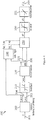
- FIG. 1 shows an embodiment of the invention.
- the Inertia Controller 200 contains the following blocks:
- the block 251 acts as a ramp rate limiter block applied to the saturated signal delta_P_IR, limiting its rate of change according to a parameter setting.
- the additional function looks at different ramp rate limits in the frequency controller and decides what ramp rate setting should be sent to the WTGs.
- the additional function receives a ramp rate value from the IEC that should be set to WTGs during inertia events.
- an additional function is implemented. This function is responsible for deciding which ramp rate the WTG should use for its power reference PrefFreq. The function makes it possible to change the WTGs ramp rate from the power plant controller or even from a remote system operator.
- a “delta_P” power is generated based on the actual frequency profile. This "delta_P” power must be added on top of the actual power produced by the WPP in the moment when the inertia event is triggered.
- a "delta_P" power is generated independent on the actual frequency profile.
- Figure 5 and Figure 6 shows an embodiment of the Power loop.
- Figure 6 shows how the requested power (plant power reference) Ptotal is added together with IRdeltaP, i.e. 260 from Figure 4 .
- the addition forms a Ptotalref, and this signal can be limited in a limit function to PrefFreq.
- a comparator selects based on rules or functions the overboost reference (PrefOB), inputs to the comparator is the available power and the total available power for the WTGs with no OB capability.
- PrefOB overboost reference
- the algorithm of calculating PrefOB starts to compare the total P with the total available power for the WTGs which have OB capability (PtotalavaOB), and the total available power for the WTGs which have NO OB capability (PtotalavaNOOB).
- PtotalavaNOOB the total available power for the WTGs which have NO OB capability
- the reason of considering PtotalavaNOOB is because the group of WTGs without OB capability could still follow wind to generate certain amount of P to contribute Ptotal to some extent, then PrefOB may be mitigated sometimes. Consequently the result of (Ptotal - PtotalavaNOOB) should be compared with PtotalavaOB to calculate PrefOB.
- Another fact regarding the WTGs which execute the OB is that they do not follow wind anymore and their wind-based P production have been locked from the moment they start to execute OB, thus PtotalavaOB is locked from the moment the OB execution starts.
- the locked PtotalavaOB should be used to calculate PrefOB.
- a variable PavaLK is used to represent the locked PtotalavaOB in this design.
- an OB flag is used to signal the OB event to the WTGs and also to enable the overboost reference (PrefOB) to be transmitted to the WTGs in the dispatcher.
- PrefOB overboost reference
- the OB flag is not present and the overboost reference (PrefOB) is always transmitted, and the WTGs act upon receiving the overboost reference (PrefOB).
- the overboost handle of the WTG is used first.
- the overboost capability of the WTG is monitored and when this capability decreases under a certain level (or alternatively, after a certain predetermined period of time) the handle is gradually changed from the overboost handle to the power reference handle. That is done by ramping down the overboost reference and accordingly ramping up the power reference.
- the overboost enabling signal to the WTGs can be disabled as soon as the overboost reference has reached zero, and thus avoiding the WTG to loose kinetic energy (i.e. the rotor speed will not decrease) - only if the overboosting power level is above the available power.
- the overboost enabling signal can be kept high until the end of the inertia sequence request, accepting the risk that in this case, if the overboost power level is above the available power, during the WTG recovery period the power will drop much below the initial level, when the inertia response was initiated.
- Figure 7 and 8 are representing the above discussion where a method of using two handles to operate the WPP during an overboost event is applied.
- Figure 7 shows an embodiment during a situation where available power 301 is higher than the power reference 302, i.e. actual power in case EN_OB 305 is active from t0 to t3, and the overboost capacity is sufficient.
- the flag or input signal enable overboost EN_OB 305 is set at time t0 and an amount of delta power is calculated for the inertial response, deltaP_IR 304.
- the overboost power P_OB_ref 306 is ramped at t0 and has reached maximum at time t+. As the EN_OB flag remains high, the request for boost power is still present, so even though the overboost power P_OB_ref starts to decline at time t1, as the overboost power decreases, the power reference takes over the requested delta power, as the power reference increases, so when adding up overboost power and power equals the requested deltaP_IR. At time t2 the overboost power is zero, and the power reference Pref_PPC 307 follows the deltaP_IR until t3 where enable overboost EN_OB goes low and deltaP_IR is ramped down to zero.
- the power reference Pref_PPC is normally not zero, but will return to a reference reflecting the power requirement at the current situation.
- the curve 302 shows the resulting power output as function of time
- the curve 303 shows a potential power under swing caused by a loss in kinetic energy, in case the available power is under the required power, which is not the case here.
- Figure 8 shows an embodiment during a situation where available power 401 is lower than the power reference, i.e. actual power in case EN_OB 405 is active from t0 to t2, and the overboost capacity is insufficient.
- the flag or input signal enable overboost EN_OB 405 is set at time t0 and an amount of delta power is calculated for the inertial response, deltaP_IR.
- the amount of delta power in Figure 7 and Figure 8 may not be equal.
- the overboost power P_OB_ref 406 is ramped at t0 and has reached maximum at time t+. As the EN_OB flag 405 remains high, the request for boost power is still present, so even though the overboost power P_OB_ref 406 starts to decline at time t1, as the overboost power decreases, the power reference takes over the requested delta power, as the power reference increases, so when adding up overboost power and power equals the requested deltaP_IR.
- the overboost power is zero, at the time the actual power 402 from the wind turbine generator starts to drop as the power available in the wind is less than the requested power, the increased power delivered until time t2 is captured by an decreased rotor speed, where the rotational kinetic energy is used as an inertial reserve.
- the EN_OB flag 405 is set to zero and the WTG starts a recovery routine, where the produced power is less than the power prior to the inertial response event.
- the lower power production helps to the WTG 100 to gain rotational speed of the rotor 102, so the WTG can operate in normal operational mode again after some seconds.
- the power plant controller receives signal from the WTGs, which return information about each of the wind turbines' capability to maintain an increased power production.
- These signals may include an:
- the power plant controller calculates how many of the plurality of WTGs in the wind power plant that has to be used in order to provide the requested inertial support.
- the inertia controller contains a block called Additional Power Calculator, delta_P 230.
- This block is responsible for generating a power increase of the WPP in accordance with the actual frequency conditions in the power system to which the WPP is connected.
- the method mentioned below is one method to derive the required power requested during the inertial response. Other methods may be similar and the invention is not limited to the disclosed embodiments of the method.
- Block 230 calculates the power change that must be produced by the WPP during inertia type frequency events.
- the Delta_P_IR Calculation block 230 is based on two different types of power reference generation. The first type is generating the power reference change when inertia control is triggered, based on the calculated ROCOF.
- the Inertia controller will be used for both directions of frequency deviations (i.e. positive and negative) in order to minimize the impact of load/generation changes in the power system, by reducing its ROCOF and in this way avoiding assets disconnection from the grid.
- Figure 9 shows a situation where the inertia controller handles an over frequency situation with fluctuating wind condition causing the produced power to variate.
- the available power is depictured in trace 702, where the power reference is shown in trace 701. Prior to time t01 the Power reference 701 is in fact higher than the available power 702.
- the inertia event request is enabled by the inertia event request 705, the signal goes high at time t01 and low at time t06.
- the change in power level given by the inertia controller (deltaP_IR) 704 is in fact negative, thus the power reference 701 is reduced by a slope from t01 to t02.
- the power production 703 is at maximum level, i.e. given by the available power 702.
- the over-frequency event occurs generating an inertia event request 705 at time t01.
- the power reference 701 is therefore formed by summing up the frozen value of the actual power production level and the power level given by the inertia controller (deltaP_IR) 704. Given the shape of the available power 702, the resulting power production will be as in 703.
- the overboost enable signal (EN_OB) 706 can be switched on between t03 and t04 such that during the available power decrease 702, the power is maintained at the requested value, by using the overboost handle of the WTG (i.e. by extracting the requested power from the rotor kinetic energy). This is done by activating the WTGs overboost enable flag 706 as mentioned above, and the WTGs provide an overboost power 707 according to a PrefOB reference.
- both handles of the WTG can be used (i.e. the power reference handle and the overboost handle).
- the electrical value of the electrical grid may be a frequency value.
- the electrical value may be a value of the frequency of the electrical grid.
- Embodiments of invention can be implemented by means of electronic hardware, software, firmware or any combination of these.
- Software implemented embodiments or features thereof may be arranged to run on one or more data processors and/or digital signal processors.
- Software is understood as a computer program or computer program product which may be stored/distributed on a suitable computer-readable medium, such as an optical storage medium or a solid-state medium supplied together with or as part of other hardware, but may also be distributed in other forms, such as via the Internet or other wired or wireless telecommunication systems.
- the computer-readable medium may be a non-transitory medium.
- the computer program comprises software code portions for performing the steps according to embodiments of the invention when the computer program product is run/executed by a computer or by a distributed computer system.
Landscapes
- Engineering & Computer Science (AREA)
- General Engineering & Computer Science (AREA)
- Mechanical Engineering (AREA)
- Sustainable Energy (AREA)
- Chemical & Material Sciences (AREA)
- Combustion & Propulsion (AREA)
- Life Sciences & Earth Sciences (AREA)
- Sustainable Development (AREA)
- Power Engineering (AREA)
- Physics & Mathematics (AREA)
- General Physics & Mathematics (AREA)
- Automation & Control Theory (AREA)
- Wind Motors (AREA)
- Control Of Eletrric Generators (AREA)
Claims (13)
- Verfahren zum Steuern eines Windparks, WPP, der eine Vielzahl von Windkraftanlagen, WTGs, umfasst, die mit einem Stromnetz verbunden sind, wobei das Verfahren umfasst:Einstellen einer Werksleistungsreferenz (Ptotal) gemäß einem elektrischen Wert des Stromnetzes;Bestimmen einer Trägheitsdelta-Leistungsreferenz (IRdeltaP), die erforderlich ist, damit das WPP eine Leistungsnachfrage als Reaktion auf eine Änderung des elektrischen Werts erfüllt;Hinzufügen der Trägheitsdelta-Leistungsreferenz (IRdeltaP) und der Werksleistungsreferenz (Ptotal), um eine Leistungsreferenz (Ptotalref) zu bilden;Ableiten einer Overboost-Referenz (PrefOB) als den Unterschied zwischen der Leistungsreferenz (Ptotalref) und einem verfügbaren Leistungswert (Pava);Senden der Leistungsreferenz (Ptotalref) zu jeder Windkraftanlage der Vielzahl von Windkraftanlagen; undSenden der Overboost-Referenz (PrefOB) zu jeder Windkraftanlage der Vielzahl von Windkraftanlagen.
- Verfahren nach Anspruch 1, wobei der elektrische Wert ein Frequenzwert ist.
- Verfahren nach Anspruch 1 oder 2, wobei das Verfahren umfasst:- Senden eines Overboost-Flag (OBFlag) zu jeder Windkraftanlage der Vielzahl von Windkraftanlagen, wodurch die Vielzahl von Windkraftanlagen ein Overboost gemäß der empfangenen Overboost-Referenz (PrefOB) initiiert.
- Verfahren nach einem der Ansprüche 1 bis 3, wobei die Leistungsreferenz (Ptotalref) und/oder die Overboost-Referenz (PrefOB) eine zeitabhängige Rampenratenfunktion mit einer vorbestimmten Rampenrate ist/sind.
- Verfahren nach einem der Ansprüche 1 bis 4, wobei das Verfahren umfasst:
Herunterfahren der Overboost-Referenz (PrefOB) nach einer vorbestimmten Zeitspanne, die von einem Timer bestimmt wird. - Verfahren nach einem der vorstehenden Ansprüche, das umfasst:Reduzieren der Werksleistungsreferenz (Ptotal) gemäß dem elektrischen Wert des Stromnetzes mit einer negativen Trägheitsdelta-Leistungsreferenz (IRdeltaP);Vergleichen der verfügbaren Leistung (Pava) mit der Leistungsreferenz (Ptotalref); undAnfordern der Overboost-Referenz (PrefOB), um eine Steigerung der Leistungserzeugung zu befehlen, wenn die Leistungsreferenz (Ptotalref) größer ist als die verfügbare Leistung.
- Verfahren nach einem der vorstehenden Ansprüche, das umfasst:Anfordern einer Änderung der Leistungsproduktion von der Windkraftanlage durch Verwenden der Leistungsreferenz (Ptotalref) und der Overboost-Referenz (PrefOB);wobei die Windkraftanlage zuerst auf die Overboost-Referenz (PrefOB) und danach auf die Leistungsreferenz (Ptotalref) reagiert; undallmähliches Ändern der Anforderung um Änderung der Leistungsproduktion durch Verringern der Overboost-Referenz (PrefOB) und Steigern der Leistungsreferenz (Ptotalref), um die Änderung der Leistungsproduktion beizubehalten.
- Verfahren nach Anspruch 7, wobei die Overboost-Referenz (PrefOB) der Windkraftanlage ein Overboost-Ereignis in der Windkraftanlage initialisiert, das kinetische Rotationsenergie, die in dem Rotor gespeichert ist, verwendet.
- Verfahren nach Anspruch 8, das weiter umfasst:Vergleichen einer Rotorgeschwindigkeit der Windkraftanlage mit einem Geschwindigkeitsschwellenwert; undDeaktivieren der Overboost-Referenz (PrefOB) als Reaktion auf die Rotorgeschwindigkeit.
- Verfahren nach Anspruch 7, wobei der Schritt des allmählichen Änderns der Anfrage um Änderung der Leistungsproduktion nach einer vorbestimmten Zeitspanne initiiert wird.
- Steuersystem zum Steuern der Ausgangsleistung eines Windparks, WPP, die eine Vielzahl von Windkraftanlagen beinhaltet, die mit einem Stromnetz verbunden sind, wobei das Steuersystem umfasst:einen oder mehrere Computerprozessoren;ein Modul zum Einstellen einer Werksleistungsreferenz (Ptotal) gemäß einem elektrischen Wert des Stromnetzes;ein Modul zum Bestimmen einer Trägheitsdelta-Leistungsreferenz (IRdeltaP), die erforderlich ist, damit das WPP eine Leistungsnachfrage als Reaktion auf eine Änderung des elektrischen Werts erfüllt;ein Modul zum Hinzufügen der Trägheitsdelta-Leistungsreferenz (IRdeltaP) und der Werksleistungsreferenz (Ptotal) um eine Leistungsreferenz (Ptotalref) zu bilden;ein Modul zum Ableiten einer Overboost-Referenz (PrefOB) als den Unterschied zwischen der Leistungsreferenz (Ptotalref) und einer verfügbaren Leistung;einen Verteiler zum Verteilen der Leistungsreferenz (Ptotalref) zu jeder Windkraftanlage der Vielzahl von Windkraftanlagen; undeinen Verteiler zum Verteilen der Overboost-Referenz (PrefOB) zu jeder Windkraftanlage der Vielzahl von Windkraftanlagen.
- Computerprogrammprodukt, das in einen internen Speicher mindestens eines digitalen Computers ladbar ist, wobei das Computerprogrammprodukt Softwarecodeabschnitte umfasst, die dazu konfiguriert sind, die Schritte des Verfahrens nach einem der Ansprüche 1 bis 10 auszuführen, wenn das Computerprogrammprodukt auf mindestens einem digitalen Computer ausgeführt wird.
- Windpark, der eine Vielzahl von Windkraftanlagen und ein Steuersystem nach Anspruch 11 umfasst.
Applications Claiming Priority (2)
| Application Number | Priority Date | Filing Date | Title |
|---|---|---|---|
| DKPA201670005 | 2016-01-06 | ||
| PCT/DK2016/050451 WO2017118460A1 (en) | 2016-01-06 | 2016-12-20 | Control of a wind power plant |
Publications (2)
| Publication Number | Publication Date |
|---|---|
| EP3400384A1 EP3400384A1 (de) | 2018-11-14 |
| EP3400384B1 true EP3400384B1 (de) | 2021-03-31 |
Family
ID=59273297
Family Applications (1)
| Application Number | Title | Priority Date | Filing Date |
|---|---|---|---|
| EP16822893.0A Active EP3400384B1 (de) | 2016-01-06 | 2016-12-20 | Steuerung einer windkraftanlage |
Country Status (4)
| Country | Link |
|---|---|
| US (1) | US11421654B2 (de) |
| EP (1) | EP3400384B1 (de) |
| CN (1) | CN108474346B (de) |
| WO (1) | WO2017118460A1 (de) |
Cited By (1)
| Publication number | Priority date | Publication date | Assignee | Title |
|---|---|---|---|---|
| EP4019768B1 (de) * | 2020-12-23 | 2025-01-29 | Technische Universität Berlin | Verfahren und system zur bestimmung eines sollwertsignals eines windenergieumwandlungssystems |
Families Citing this family (23)
| Publication number | Priority date | Publication date | Assignee | Title |
|---|---|---|---|---|
| EP3314118B1 (de) * | 2015-06-26 | 2019-08-07 | Vestas Wind Systems A/S | Erhöhung der wirkleistung einer windturbine |
| US11421654B2 (en) | 2016-01-06 | 2022-08-23 | Vestas Wind Systems A/S | Control of a wind power plant |
| DE102016101469A1 (de) * | 2016-01-27 | 2017-07-27 | Wobben Properties Gmbh | Verfahren zum Einspeisen elektrischer Leistung in ein elektrisches Versorgungsnetz |
| US10855082B2 (en) * | 2016-05-25 | 2020-12-01 | Vestas Wind Systems A/S | Operating a wind turbine generator during an abnormal grid event |
| ES2817534T3 (es) * | 2016-07-06 | 2021-04-07 | Vestas Wind Sys As | Una instalación de energía eólica que tiene una pluralidad de generadores de turbina eólica y un controlador de instalación de energía |
| CN113039695B (zh) * | 2018-09-19 | 2025-08-26 | 维斯塔斯风力系统集团公司 | 混合动力发电厂及控制混合动力发电厂的方法 |
| CN109193804B (zh) * | 2018-10-17 | 2021-10-29 | 河海大学 | 基于动能存储的风电场风机协同综合控制的功率平滑方法 |
| US11799290B2 (en) | 2019-02-28 | 2023-10-24 | Vestas Wind Systems A/S | Method for controlling a power plant |
| ES2986182T3 (es) | 2019-06-03 | 2024-11-08 | Vestas Wind Sys As | Priorización de puntos de consigna de energía para unidades de generación de energía en una central eléctrica |
| US10975847B1 (en) * | 2019-11-08 | 2021-04-13 | General Electric Company | System and method for farm-level control of transient power boost during frequency events |
| US10989169B1 (en) | 2019-11-15 | 2021-04-27 | General Electric Company | System and method for controlling a wind farm |
| KR102243317B1 (ko) * | 2019-11-29 | 2021-04-21 | 재단법인 녹색에너지연구원 | 가변속 풍력발전기의 주파수 제어시스템 및 제어방법 |
| EP4094340B1 (de) * | 2020-01-22 | 2025-05-14 | Vestas Wind Systems A/S | Steuerung eines kraftwerks für erneuerbare energien als reaktion auf ein null-leistungsbedarfssignal |
| WO2022089702A1 (en) * | 2020-10-27 | 2022-05-05 | Vestas Wind Systems A/S | Methods and systems for controlling a wind turbine generator in response to a frequency deviation |
| ES3037013T3 (en) * | 2020-11-13 | 2025-09-26 | Vestas Wind Sys As | Controlling a power plant comprising wind turbines during grid frequency deviation |
| US11411403B2 (en) | 2020-12-14 | 2022-08-09 | Vestas Wind Systems A/S | Controlling power distribution at deadband states |
| EP4075630A1 (de) * | 2021-04-16 | 2022-10-19 | Siemens Gamesa Renewable Energy Innovation & Technology S.L. | Windturbinensteuerungssystem und -verfahren |
| EP4089277B1 (de) | 2021-05-12 | 2025-07-23 | General Electric Renovables España S.L. | Verfahren zum betrieb einer windturbine und kraftwerk |
| CN113890062B (zh) * | 2021-10-18 | 2023-08-25 | 中国华能集团清洁能源技术研究院有限公司 | 一种用于风力发电机组一次调频功率控制的方法 |
| US20250174997A1 (en) * | 2022-03-02 | 2025-05-29 | Vestas Wind Systems A/S | A method for controlling a power plant |
| US12483031B2 (en) | 2022-04-20 | 2025-11-25 | Vestas Wind Systems A/S | Methods and systems for controlling a power plant during network frequency fluctuations |
| US12556001B2 (en) | 2022-05-06 | 2026-02-17 | Ge Vernova Infrastructure Technology Llc | System and method for controlling a plurality of power generators |
| US12392322B1 (en) * | 2024-07-09 | 2025-08-19 | Vestas Wind Systems A/S | Wind turbine spinning reserve with selectable confidence level |
Family Cites Families (16)
| Publication number | Priority date | Publication date | Assignee | Title |
|---|---|---|---|---|
| US8237301B2 (en) | 2008-01-31 | 2012-08-07 | General Electric Company | Power generation stabilization control systems and methods |
| US8977402B2 (en) | 2008-06-30 | 2015-03-10 | Vestas Wind Systems A/S | Method and system for operating a wind power plant comprising a number of wind turbine generators |
| US20110285130A1 (en) * | 2009-01-30 | 2011-11-24 | Jan Thisted | Power System Frequency Inertia for Wind Turbines |
| DE102010014165A1 (de) | 2010-04-08 | 2011-10-13 | Repower Systems Ag | Dynamische Trägheitsregelung |
| EP2577831B1 (de) * | 2010-06-03 | 2019-03-06 | Vestas Wind Systems A/S | Verfahren und steueranordnung zur steuerung der zentralen kondensatoren bei windenergieanlagen |
| US9222466B2 (en) * | 2010-08-13 | 2015-12-29 | Vestas Wind Systems A/S | Wind-power production with reduced power fluctuations |
| JP5439340B2 (ja) * | 2010-10-29 | 2014-03-12 | 三菱重工業株式会社 | ウインドファームの制御装置、ウインドファーム、及びウインドファームの制御方法 |
| JP2012143079A (ja) * | 2010-12-28 | 2012-07-26 | Mitsubishi Heavy Ind Ltd | ケーブル支持具 |
| US9728969B2 (en) * | 2011-05-31 | 2017-08-08 | Vestas Wind Systems A/S | Systems and methods for generating an inertial response to a change in the voltage of an electricial grid |
| DK2532888T4 (da) * | 2011-06-08 | 2021-09-13 | Siemens Gamesa Renewable Energy As | Anordning til generering af et styresignal til styring af et effektoutput fra et effektgenereringssystem |
| CN103562545B (zh) * | 2011-08-10 | 2015-07-15 | 三菱重工业株式会社 | 风力发电站的控制装置及风力发电站的控制方法 |
| CN104969436B (zh) * | 2013-02-07 | 2018-05-22 | 维斯塔斯风力系统集团公司 | 用于提供电网辅助服务的发电厂和能量存储系统 |
| ES2545674B1 (es) | 2014-03-11 | 2016-06-29 | Gamesa Innovation & Technology, S.L. | Sistema de control de inercia para aerogenerador |
| KR101450147B1 (ko) * | 2014-08-05 | 2014-10-13 | 전북대학교산학협력단 | 풍력발전기의 관성제어 방법 |
| US20160160839A1 (en) * | 2014-12-09 | 2016-06-09 | State Grid Corporation Of China | Method for controlling inertia response of variable-speed wind turbine generator |
| US11421654B2 (en) | 2016-01-06 | 2022-08-23 | Vestas Wind Systems A/S | Control of a wind power plant |
-
2016
- 2016-12-20 US US16/067,786 patent/US11421654B2/en active Active
- 2016-12-20 WO PCT/DK2016/050451 patent/WO2017118460A1/en not_active Ceased
- 2016-12-20 CN CN201680078171.3A patent/CN108474346B/zh active Active
- 2016-12-20 EP EP16822893.0A patent/EP3400384B1/de active Active
Non-Patent Citations (1)
| Title |
|---|
| None * |
Cited By (1)
| Publication number | Priority date | Publication date | Assignee | Title |
|---|---|---|---|---|
| EP4019768B1 (de) * | 2020-12-23 | 2025-01-29 | Technische Universität Berlin | Verfahren und system zur bestimmung eines sollwertsignals eines windenergieumwandlungssystems |
Also Published As
| Publication number | Publication date |
|---|---|
| CN108474346A (zh) | 2018-08-31 |
| EP3400384A1 (de) | 2018-11-14 |
| WO2017118460A1 (en) | 2017-07-13 |
| US20190003456A1 (en) | 2019-01-03 |
| CN108474346B (zh) | 2020-09-11 |
| US11421654B2 (en) | 2022-08-23 |
Similar Documents
| Publication | Publication Date | Title |
|---|---|---|
| EP3400384B1 (de) | Steuerung einer windkraftanlage | |
| US10418925B2 (en) | Wind turbine providing grid support | |
| US10451038B2 (en) | Increasing active power from a wind turbine | |
| US9450416B2 (en) | Wind turbine generator controller responsive to grid frequency change | |
| EP2307715B2 (de) | Leistungsreduzierung von Windturbinen | |
| CN108350862B (zh) | 使用模型预测控制的风力涡轮机的电力增强 | |
| CN104321944B (zh) | 用于协调传统发电厂与风力发电厂之间的频率控制特性的方法 | |
| CN107453410B (zh) | 负荷扰动的双馈风机参与风柴微网调频控制方法 | |
| EP3462559A1 (de) | Fehlerüberbrückung zur lastaufprallminimierung | |
| EP2859638A2 (de) | Steuerung einer windkraftanlage nach niederspannungsnetzdefekten | |
| CN108138746B (zh) | 通过使降额功率输出和降额转子速度斜变而改变功率输出 | |
| KR101141090B1 (ko) | 풍력 발전 장치의 제어 장치, 윈드팜, 및 풍력 발전 장치의 제어 방법 | |
| EP3075052A1 (de) | Windkraftanlage mit verbesserter anstiegszeit | |
| US20130169241A1 (en) | Control method of a wind turbine generator | |
| EP3308016B1 (de) | Steigerung der leistung in einer windturbine je nach geschätzter verfügbarer windkraft | |
| WO2016184470A1 (en) | Method and system for controlling a wind turbine generator | |
| US11525433B2 (en) | Power ramp rate control | |
| EP4116578A1 (de) | Steuereinheit für eine windenergieanlage, windenergieanlage, steuerverfahren und steuerprogramm für eine windenergieanlage und aufzeichnungsmedium | |
| CN115492718A (zh) | 用于一次调频的有功功率控制方法、系统、设备及介质 |
Legal Events
| Date | Code | Title | Description |
|---|---|---|---|
| STAA | Information on the status of an ep patent application or granted ep patent |
Free format text: STATUS: UNKNOWN |
|
| STAA | Information on the status of an ep patent application or granted ep patent |
Free format text: STATUS: THE INTERNATIONAL PUBLICATION HAS BEEN MADE |
|
| PUAI | Public reference made under article 153(3) epc to a published international application that has entered the european phase |
Free format text: ORIGINAL CODE: 0009012 |
|
| STAA | Information on the status of an ep patent application or granted ep patent |
Free format text: STATUS: REQUEST FOR EXAMINATION WAS MADE |
|
| 17P | Request for examination filed |
Effective date: 20180706 |
|
| AK | Designated contracting states |
Kind code of ref document: A1 Designated state(s): AL AT BE BG CH CY CZ DE DK EE ES FI FR GB GR HR HU IE IS IT LI LT LU LV MC MK MT NL NO PL PT RO RS SE SI SK SM TR |
|
| AX | Request for extension of the european patent |
Extension state: BA ME |
|
| DAV | Request for validation of the european patent (deleted) | ||
| DAX | Request for extension of the european patent (deleted) | ||
| GRAP | Despatch of communication of intention to grant a patent |
Free format text: ORIGINAL CODE: EPIDOSNIGR1 |
|
| STAA | Information on the status of an ep patent application or granted ep patent |
Free format text: STATUS: GRANT OF PATENT IS INTENDED |
|
| INTG | Intention to grant announced |
Effective date: 20201118 |
|
| GRAS | Grant fee paid |
Free format text: ORIGINAL CODE: EPIDOSNIGR3 |
|
| GRAA | (expected) grant |
Free format text: ORIGINAL CODE: 0009210 |
|
| STAA | Information on the status of an ep patent application or granted ep patent |
Free format text: STATUS: THE PATENT HAS BEEN GRANTED |
|
| RIN1 | Information on inventor provided before grant (corrected) |
Inventor name: NAYEBI, KOUROUSH Inventor name: WEI, MU Inventor name: VALCAN, DUMITRU-MIHAI Inventor name: GARCIA, JORGE MARTINEZ |
|
| AK | Designated contracting states |
Kind code of ref document: B1 Designated state(s): AL AT BE BG CH CY CZ DE DK EE ES FI FR GB GR HR HU IE IS IT LI LT LU LV MC MK MT NL NO PL PT RO RS SE SI SK SM TR |
|
| REG | Reference to a national code |
Ref country code: GB Ref legal event code: FG4D Ref country code: CH Ref legal event code: EP |
|
| REG | Reference to a national code |
Ref country code: DE Ref legal event code: R096 Ref document number: 602016055351 Country of ref document: DE Ref country code: AT Ref legal event code: REF Ref document number: 1377216 Country of ref document: AT Kind code of ref document: T Effective date: 20210415 |
|
| REG | Reference to a national code |
Ref country code: IE Ref legal event code: FG4D |
|
| REG | Reference to a national code |
Ref country code: LT Ref legal event code: MG9D |
|
| PG25 | Lapsed in a contracting state [announced via postgrant information from national office to epo] |
Ref country code: NO Free format text: LAPSE BECAUSE OF FAILURE TO SUBMIT A TRANSLATION OF THE DESCRIPTION OR TO PAY THE FEE WITHIN THE PRESCRIBED TIME-LIMIT Effective date: 20210630 Ref country code: FI Free format text: LAPSE BECAUSE OF FAILURE TO SUBMIT A TRANSLATION OF THE DESCRIPTION OR TO PAY THE FEE WITHIN THE PRESCRIBED TIME-LIMIT Effective date: 20210331 Ref country code: HR Free format text: LAPSE BECAUSE OF FAILURE TO SUBMIT A TRANSLATION OF THE DESCRIPTION OR TO PAY THE FEE WITHIN THE PRESCRIBED TIME-LIMIT Effective date: 20210331 Ref country code: BG Free format text: LAPSE BECAUSE OF FAILURE TO SUBMIT A TRANSLATION OF THE DESCRIPTION OR TO PAY THE FEE WITHIN THE PRESCRIBED TIME-LIMIT Effective date: 20210630 |
|
| PG25 | Lapsed in a contracting state [announced via postgrant information from national office to epo] |
Ref country code: SE Free format text: LAPSE BECAUSE OF FAILURE TO SUBMIT A TRANSLATION OF THE DESCRIPTION OR TO PAY THE FEE WITHIN THE PRESCRIBED TIME-LIMIT Effective date: 20210331 Ref country code: LV Free format text: LAPSE BECAUSE OF FAILURE TO SUBMIT A TRANSLATION OF THE DESCRIPTION OR TO PAY THE FEE WITHIN THE PRESCRIBED TIME-LIMIT Effective date: 20210331 Ref country code: RS Free format text: LAPSE BECAUSE OF FAILURE TO SUBMIT A TRANSLATION OF THE DESCRIPTION OR TO PAY THE FEE WITHIN THE PRESCRIBED TIME-LIMIT Effective date: 20210331 |
|
| REG | Reference to a national code |
Ref country code: NL Ref legal event code: MP Effective date: 20210331 |
|
| REG | Reference to a national code |
Ref country code: AT Ref legal event code: MK05 Ref document number: 1377216 Country of ref document: AT Kind code of ref document: T Effective date: 20210331 |
|
| PG25 | Lapsed in a contracting state [announced via postgrant information from national office to epo] |
Ref country code: LT Free format text: LAPSE BECAUSE OF FAILURE TO SUBMIT A TRANSLATION OF THE DESCRIPTION OR TO PAY THE FEE WITHIN THE PRESCRIBED TIME-LIMIT Effective date: 20210331 Ref country code: NL Free format text: LAPSE BECAUSE OF FAILURE TO SUBMIT A TRANSLATION OF THE DESCRIPTION OR TO PAY THE FEE WITHIN THE PRESCRIBED TIME-LIMIT Effective date: 20210331 Ref country code: EE Free format text: LAPSE BECAUSE OF FAILURE TO SUBMIT A TRANSLATION OF THE DESCRIPTION OR TO PAY THE FEE WITHIN THE PRESCRIBED TIME-LIMIT Effective date: 20210331 Ref country code: CZ Free format text: LAPSE BECAUSE OF FAILURE TO SUBMIT A TRANSLATION OF THE DESCRIPTION OR TO PAY THE FEE WITHIN THE PRESCRIBED TIME-LIMIT Effective date: 20210331 Ref country code: SM Free format text: LAPSE BECAUSE OF FAILURE TO SUBMIT A TRANSLATION OF THE DESCRIPTION OR TO PAY THE FEE WITHIN THE PRESCRIBED TIME-LIMIT Effective date: 20210331 Ref country code: AT Free format text: LAPSE BECAUSE OF FAILURE TO SUBMIT A TRANSLATION OF THE DESCRIPTION OR TO PAY THE FEE WITHIN THE PRESCRIBED TIME-LIMIT Effective date: 20210331 |
|
| PG25 | Lapsed in a contracting state [announced via postgrant information from national office to epo] |
Ref country code: SK Free format text: LAPSE BECAUSE OF FAILURE TO SUBMIT A TRANSLATION OF THE DESCRIPTION OR TO PAY THE FEE WITHIN THE PRESCRIBED TIME-LIMIT Effective date: 20210331 Ref country code: RO Free format text: LAPSE BECAUSE OF FAILURE TO SUBMIT A TRANSLATION OF THE DESCRIPTION OR TO PAY THE FEE WITHIN THE PRESCRIBED TIME-LIMIT Effective date: 20210331 Ref country code: PT Free format text: LAPSE BECAUSE OF FAILURE TO SUBMIT A TRANSLATION OF THE DESCRIPTION OR TO PAY THE FEE WITHIN THE PRESCRIBED TIME-LIMIT Effective date: 20210802 Ref country code: PL Free format text: LAPSE BECAUSE OF FAILURE TO SUBMIT A TRANSLATION OF THE DESCRIPTION OR TO PAY THE FEE WITHIN THE PRESCRIBED TIME-LIMIT Effective date: 20210331 Ref country code: IS Free format text: LAPSE BECAUSE OF FAILURE TO SUBMIT A TRANSLATION OF THE DESCRIPTION OR TO PAY THE FEE WITHIN THE PRESCRIBED TIME-LIMIT Effective date: 20210731 |
|
| REG | Reference to a national code |
Ref country code: DE Ref legal event code: R097 Ref document number: 602016055351 Country of ref document: DE |
|
| PG25 | Lapsed in a contracting state [announced via postgrant information from national office to epo] |
Ref country code: DK Free format text: LAPSE BECAUSE OF FAILURE TO SUBMIT A TRANSLATION OF THE DESCRIPTION OR TO PAY THE FEE WITHIN THE PRESCRIBED TIME-LIMIT Effective date: 20210331 Ref country code: AL Free format text: LAPSE BECAUSE OF FAILURE TO SUBMIT A TRANSLATION OF THE DESCRIPTION OR TO PAY THE FEE WITHIN THE PRESCRIBED TIME-LIMIT Effective date: 20210331 Ref country code: ES Free format text: LAPSE BECAUSE OF FAILURE TO SUBMIT A TRANSLATION OF THE DESCRIPTION OR TO PAY THE FEE WITHIN THE PRESCRIBED TIME-LIMIT Effective date: 20210331 |
|
| PLBE | No opposition filed within time limit |
Free format text: ORIGINAL CODE: 0009261 |
|
| STAA | Information on the status of an ep patent application or granted ep patent |
Free format text: STATUS: NO OPPOSITION FILED WITHIN TIME LIMIT |
|
| 26N | No opposition filed |
Effective date: 20220104 |
|
| PG25 | Lapsed in a contracting state [announced via postgrant information from national office to epo] |
Ref country code: IS Free format text: LAPSE BECAUSE OF FAILURE TO SUBMIT A TRANSLATION OF THE DESCRIPTION OR TO PAY THE FEE WITHIN THE PRESCRIBED TIME-LIMIT Effective date: 20210731 |
|
| PG25 | Lapsed in a contracting state [announced via postgrant information from national office to epo] |
Ref country code: MC Free format text: LAPSE BECAUSE OF FAILURE TO SUBMIT A TRANSLATION OF THE DESCRIPTION OR TO PAY THE FEE WITHIN THE PRESCRIBED TIME-LIMIT Effective date: 20210331 Ref country code: IT Free format text: LAPSE BECAUSE OF FAILURE TO SUBMIT A TRANSLATION OF THE DESCRIPTION OR TO PAY THE FEE WITHIN THE PRESCRIBED TIME-LIMIT Effective date: 20210331 |
|
| REG | Reference to a national code |
Ref country code: CH Ref legal event code: PL |
|
| REG | Reference to a national code |
Ref country code: BE Ref legal event code: MM Effective date: 20211231 |
|
| PG25 | Lapsed in a contracting state [announced via postgrant information from national office to epo] |
Ref country code: LU Free format text: LAPSE BECAUSE OF NON-PAYMENT OF DUE FEES Effective date: 20211220 Ref country code: IE Free format text: LAPSE BECAUSE OF NON-PAYMENT OF DUE FEES Effective date: 20211220 |
|
| PG25 | Lapsed in a contracting state [announced via postgrant information from national office to epo] |
Ref country code: BE Free format text: LAPSE BECAUSE OF NON-PAYMENT OF DUE FEES Effective date: 20211231 |
|
| PG25 | Lapsed in a contracting state [announced via postgrant information from national office to epo] |
Ref country code: LI Free format text: LAPSE BECAUSE OF NON-PAYMENT OF DUE FEES Effective date: 20211231 Ref country code: CH Free format text: LAPSE BECAUSE OF NON-PAYMENT OF DUE FEES Effective date: 20211231 |
|
| P01 | Opt-out of the competence of the unified patent court (upc) registered |
Effective date: 20230521 |
|
| PG25 | Lapsed in a contracting state [announced via postgrant information from national office to epo] |
Ref country code: CY Free format text: LAPSE BECAUSE OF FAILURE TO SUBMIT A TRANSLATION OF THE DESCRIPTION OR TO PAY THE FEE WITHIN THE PRESCRIBED TIME-LIMIT Effective date: 20210331 |
|
| PG25 | Lapsed in a contracting state [announced via postgrant information from national office to epo] |
Ref country code: HU Free format text: LAPSE BECAUSE OF FAILURE TO SUBMIT A TRANSLATION OF THE DESCRIPTION OR TO PAY THE FEE WITHIN THE PRESCRIBED TIME-LIMIT; INVALID AB INITIO Effective date: 20161220 Ref country code: GR Free format text: LAPSE BECAUSE OF FAILURE TO SUBMIT A TRANSLATION OF THE DESCRIPTION OR TO PAY THE FEE WITHIN THE PRESCRIBED TIME-LIMIT Effective date: 20210331 |
|
| PG25 | Lapsed in a contracting state [announced via postgrant information from national office to epo] |
Ref country code: MK Free format text: LAPSE BECAUSE OF FAILURE TO SUBMIT A TRANSLATION OF THE DESCRIPTION OR TO PAY THE FEE WITHIN THE PRESCRIBED TIME-LIMIT Effective date: 20210331 |
|
| PG25 | Lapsed in a contracting state [announced via postgrant information from national office to epo] |
Ref country code: MT Free format text: LAPSE BECAUSE OF FAILURE TO SUBMIT A TRANSLATION OF THE DESCRIPTION OR TO PAY THE FEE WITHIN THE PRESCRIBED TIME-LIMIT Effective date: 20210331 |
|
| PG25 | Lapsed in a contracting state [announced via postgrant information from national office to epo] |
Ref country code: TR Free format text: LAPSE BECAUSE OF FAILURE TO SUBMIT A TRANSLATION OF THE DESCRIPTION OR TO PAY THE FEE WITHIN THE PRESCRIBED TIME-LIMIT Effective date: 20210331 |
|
| PGFP | Annual fee paid to national office [announced via postgrant information from national office to epo] |
Ref country code: GB Payment date: 20251223 Year of fee payment: 10 |
|
| PGFP | Annual fee paid to national office [announced via postgrant information from national office to epo] |
Ref country code: FR Payment date: 20251223 Year of fee payment: 10 |
|
| PGFP | Annual fee paid to national office [announced via postgrant information from national office to epo] |
Ref country code: DE Payment date: 20251229 Year of fee payment: 10 |