EP4019768B1 - Verfahren und system zur bestimmung eines sollwertsignals eines windenergieumwandlungssystems - Google Patents
Verfahren und system zur bestimmung eines sollwertsignals eines windenergieumwandlungssystems Download PDFInfo
- Publication number
- EP4019768B1 EP4019768B1 EP20216978.5A EP20216978A EP4019768B1 EP 4019768 B1 EP4019768 B1 EP 4019768B1 EP 20216978 A EP20216978 A EP 20216978A EP 4019768 B1 EP4019768 B1 EP 4019768B1
- Authority
- EP
- European Patent Office
- Prior art keywords
- power
- signal
- determining
- frequency
- value
- Prior art date
- Legal status (The legal status is an assumption and is not a legal conclusion. Google has not performed a legal analysis and makes no representation as to the accuracy of the status listed.)
- Active
Links
Images


Classifications
-
- F—MECHANICAL ENGINEERING; LIGHTING; HEATING; WEAPONS; BLASTING
- F03—MACHINES OR ENGINES FOR LIQUIDS; WIND, SPRING, OR WEIGHT MOTORS; PRODUCING MECHANICAL POWER OR A REACTIVE PROPULSIVE THRUST, NOT OTHERWISE PROVIDED FOR
- F03D—WIND MOTORS
- F03D7/00—Controlling wind motors
- F03D7/02—Controlling wind motors the wind motors having rotation axis substantially parallel to the air flow entering the rotor
- F03D7/028—Controlling wind motors the wind motors having rotation axis substantially parallel to the air flow entering the rotor controlling wind motor output power
- F03D7/0284—Controlling wind motors the wind motors having rotation axis substantially parallel to the air flow entering the rotor controlling wind motor output power in relation to the state of the electric grid
-
- F—MECHANICAL ENGINEERING; LIGHTING; HEATING; WEAPONS; BLASTING
- F03—MACHINES OR ENGINES FOR LIQUIDS; WIND, SPRING, OR WEIGHT MOTORS; PRODUCING MECHANICAL POWER OR A REACTIVE PROPULSIVE THRUST, NOT OTHERWISE PROVIDED FOR
- F03D—WIND MOTORS
- F03D7/00—Controlling wind motors
- F03D7/02—Controlling wind motors the wind motors having rotation axis substantially parallel to the air flow entering the rotor
- F03D7/0272—Controlling wind motors the wind motors having rotation axis substantially parallel to the air flow entering the rotor by measures acting on the electrical generator
-
- F—MECHANICAL ENGINEERING; LIGHTING; HEATING; WEAPONS; BLASTING
- F03—MACHINES OR ENGINES FOR LIQUIDS; WIND, SPRING, OR WEIGHT MOTORS; PRODUCING MECHANICAL POWER OR A REACTIVE PROPULSIVE THRUST, NOT OTHERWISE PROVIDED FOR
- F03D—WIND MOTORS
- F03D7/00—Controlling wind motors
- F03D7/02—Controlling wind motors the wind motors having rotation axis substantially parallel to the air flow entering the rotor
- F03D7/0276—Controlling wind motors the wind motors having rotation axis substantially parallel to the air flow entering the rotor controlling rotor speed, e.g. variable speed
-
- F—MECHANICAL ENGINEERING; LIGHTING; HEATING; WEAPONS; BLASTING
- F03—MACHINES OR ENGINES FOR LIQUIDS; WIND, SPRING, OR WEIGHT MOTORS; PRODUCING MECHANICAL POWER OR A REACTIVE PROPULSIVE THRUST, NOT OTHERWISE PROVIDED FOR
- F03D—WIND MOTORS
- F03D7/00—Controlling wind motors
- F03D7/02—Controlling wind motors the wind motors having rotation axis substantially parallel to the air flow entering the rotor
- F03D7/04—Automatic control; Regulation
- F03D7/042—Automatic control; Regulation by means of an electrical or electronic controller
-
- F—MECHANICAL ENGINEERING; LIGHTING; HEATING; WEAPONS; BLASTING
- F05—INDEXING SCHEMES RELATING TO ENGINES OR PUMPS IN VARIOUS SUBCLASSES OF CLASSES F01-F04
- F05B—INDEXING SCHEME RELATING TO WIND, SPRING, WEIGHT, INERTIA OR LIKE MOTORS, TO MACHINES OR ENGINES FOR LIQUIDS COVERED BY SUBCLASSES F03B, F03D AND F03G
- F05B2220/00—Application
- F05B2220/30—Application in turbines
-
- F—MECHANICAL ENGINEERING; LIGHTING; HEATING; WEAPONS; BLASTING
- F05—INDEXING SCHEMES RELATING TO ENGINES OR PUMPS IN VARIOUS SUBCLASSES OF CLASSES F01-F04
- F05D—INDEXING SCHEME FOR ASPECTS RELATING TO NON-POSITIVE-DISPLACEMENT MACHINES OR ENGINES, GAS-TURBINES OR JET-PROPULSION PLANTS
- F05D2270/00—Control
- F05D2270/01—Purpose of the control system
- F05D2270/05—Purpose of the control system to affect the output of the engine
- F05D2270/053—Explicitly mentioned power
-
- Y—GENERAL TAGGING OF NEW TECHNOLOGICAL DEVELOPMENTS; GENERAL TAGGING OF CROSS-SECTIONAL TECHNOLOGIES SPANNING OVER SEVERAL SECTIONS OF THE IPC; TECHNICAL SUBJECTS COVERED BY FORMER USPC CROSS-REFERENCE ART COLLECTIONS [XRACs] AND DIGESTS
- Y02—TECHNOLOGIES OR APPLICATIONS FOR MITIGATION OR ADAPTATION AGAINST CLIMATE CHANGE
- Y02E—REDUCTION OF GREENHOUSE GAS [GHG] EMISSIONS, RELATED TO ENERGY GENERATION, TRANSMISSION OR DISTRIBUTION
- Y02E10/00—Energy generation through renewable energy sources
- Y02E10/70—Wind energy
- Y02E10/72—Wind turbines with rotation axis in wind direction
Definitions
- the present disclosure refers to a method and a system for determining a setpoint signal of a wind energy conversion system.
- WECS Wind energy conversion systems
- the output power of the WECS can be regulated to mitigate the system frequency variations by modifying the control of the WECS.
- modified pitch angle control methods to minimize output power fluctuations of WECS via aerodynamic power curtailment are known.
- these methods result in an average decrease of the output power of the WECS.
- the document US 2016/040653 A1 relates to an inertial control method of a wind turbine including the steps of acquiring frequency information of a power grid, calculating a time variant droop coefficient when the frequency information is reduced below a preset range, and controlling the wind turbine using the calculated time variant droop coefficient.
- the step of calculating a time variant droop coefficient includes the steps of collecting rotor speed information changing according to the inertial control, and calculating the time variant droop coefficient using the collected rotor speed information.
- a method of controlling inertia response of variable-speed wind turbine generator is described.
- a maximum wind power of the wind turbine is gotten through a wind speed and a rotation speed at the hub of the wind turbine based on a maximum wind power tracking control strategy.
- the maximum wind power is set as an active power control reference value of the wind turbine.
- a grid frequency is obtained via a frequency measurement equipment.
- An additional active power control reference value of the wind turbine is generated based on the grid frequency via an additional control block, and the additional active power control reference value is added on the active power control reference value, wherein a total of active power control reference value of the wind turbine is the sum of the active power control reference value and the additional active power control reference value.
- WO 2020/031085 A1 discloses controlling electric power generators provided with rotational inertia. Filtering elements are used for measuring frequency related to rotation velocity of the rotor/turbine of the power generator.
- a method for determining a setpoint signal of a wind energy conversion system according to independent claim 1 is provided. Further, a system for determining a setpoint signal of a wind energy conversion system according to independent claim 11 is provided. Further embodiments are disclosed in dependent claims.
- the technology proposed allows for exploiting cyclical variations of the system frequency associated with cyclical variations of the wind speed so as to mitigate the periodic frequency variations.
- the wind energy conversion system may be connected, in particular electrically connected, to the electric power system.
- the wind energy conversion system can be one of a wind power plant, a wind turbine, a plurality of wind power plants, a plurality wind turbines.
- the wind energy conversion system comprises a rotor.
- setting the output power of the wind energy conversion system may comprise storing or releasing kinetic energy of the rotor.
- the angular speed value refers to the angular speed value of the rotor. Setting the output power may affect the angular speed of the rotor.
- the electric power system can be utilized or applied for transmitting and / or distributing electric power. Electric power can be transferred between the wind energy conversion system and the electric power system.
- the system frequency values of the electric power system may deviate around the target frequency value.
- the target frequency value may be a target value of the electric power system and, for example, be 16.7 Hz, 50 Hz, or 60 Hz.
- the system for determining the setpoint signal of the wind energy conversion system may be coupled with and / or connected to the wind energy conversion system and / or the electric power system, preferably allowing for signal transfer.
- the system may be included in the wind energy conversion system, for example in control units of the wind energy conversion system.
- the system may also be separated from the wind energy conversion system.
- the system may comprise a first, a second, and a third signal processing device.
- Each of the first, the second, and the third signal processing device can be a separate processor.
- the first, the second, and the third signal processing device can be integrated in a single processor.
- the power correction signal may be determined in a first module. Further, the first reference signal may be determined in a second module. The setpoint signal may be determined in a third module. The first, the second, and the third module may be implemented in the first, the second, and the third signal processing device, respectively. At least one of or all of the first, the second, and the third module may also be implemented in a shared signal processing device.
- Determining the intermediate signal and the power correction signal may be performed in the first signal processing device, determining the first reference signal may be performed in the second signal processing device, and determining the setpoint signal may performed in the third signal processing device.
- the first module may be a frequency-dependent power compensator.
- the first module may be configured to mitigate the system frequency variations.
- the second module may be a maximum power point estimator.
- the point of maximum power extraction of the wind energy conversion system may comprise an estimate for a maximally extractable power from wind and / or an optimum angular speed value, preferably for which the maximally extractable power is achieved.
- the third module may be configured to provide an operation within a safe operating region of the wind energy conversion system.
- the first module may comprise a first submodule for mitigating periodic frequency variations, generating a periodic power correction signal, and / or a second submodule for mitigating aperiodic frequency variations, generating an aperiodic power correction signal.
- the power correction signal may be a sum of the periodic power correction signal and the aperiodic power correction signal.
- the first submodule and / or the second submodule may be activated or deactivated.
- the method comprises determining at least one frequency component from the first input signal.
- At least one periodic frequency component may be determined from the first input signal.
- the at least one frequency component, in particular the at least one periodic frequency component may be a value or a value range between 10 -7 Hz and 10 2 Hz, preferably between 10 -5 Hz and 10 Hz, more preferably between 10 -4 Hz and 1 Hz.
- the at least one frequency component, in particular the at least one periodic frequency component may indicate an oscillation or a range of oscillations of the system frequency values. Further, a plurality of frequency components and / or periodic frequency components may be determined.
- the method may comprise determining, from the intermediate signal, a spectrum of the system frequency deviation values, the spectrum comprising the at least one frequency component.
- the spectrum may comprise a magnitude of the at least one frequency component.
- the spectrum may comprise a plurality of frequency components and, preferably, one of a plurality of magnitudes for each of the plurality of frequency components.
- the system frequency deviation values may be determined by subtracting the target frequency value from the system frequency values.
- the spectrum may be determined by applying an integral transform on the system frequency deviation values of a time window.
- the time window may have a window size (corresponding to a difference between a starting time and an ending time of the time window) of one of 5 minutes, 8 minutes, 10 minutes, 12 minutes, 15 minutes.
- the integral transform may be a discrete integral transform, particularly one of a discrete cosine transform (DCT), a discrete sine transform (DST), and a discrete Fourier transform (DFT), preferably a fast Fourier transform (FFT).
- the integral transform may be calculated at the end of the time window.
- a plurality of spectra may be determined from a plurality of time windows. The time windows may overlap. It may be provided that each of the plurality of spectra is determined after a predefined time step.
- the time step may be constant and be, for example, one of 30 seconds, 1 minute, 90 seconds, 2 minutes, and 5 minutes.
- the method may comprise determining a first filtered signal by filtering, preferably band-pass filtering, the intermediate signal, employing a frequency band.
- the band-pass filtering of the intermediate signal may be carried out by a band-pass filtering unit comprising a band-pass.
- the band-pass filtering of the intermediate signal may comprise passing first frequency components of the frequency band and attenuating and / or removing second frequency components outside the frequency band.
- the band-pass may comprise a passband width between 0.1 mHz and 10 mHz, preferably between 1 mHz and 3 mHz, more preferably 2 mHz.
- the band-pass may comprise a center frequency between 10 -7 Hz and 10 2 Hz, preferably between 10 -5 Hz and 10 Hz, more preferably between 10 -4 Hz and 1 Hz.
- the band pass-filtering of the intermediate signal may comprise employing a plurality of frequency bands, preferably by employing a plurality of band-passes, each in one of a plurality of band-pass filter units.
- the plurality of band-pass filter units may be arranged serially or, preferably, in parallel.
- a number of band-pass filter units may be variable. The number of band-pass filter units may be chosen depending on characteristics of the first input signal.
- the method may comprise determining the frequency band from the spectrum.
- the frequency band may comprise a dominating frequency component of the spectrum.
- the dominating frequency component may comprise a largest magnitude of frequency components.
- the dominating frequency component may be a value or a value range between 10 -7 Hz and 10 2 Hz, preferably between 10 -5 Hz and 10 Hz, more preferably between 10 -4 Hz and 1 Hz.
- a plurality of frequency bands each with one of a plurality of dominating frequency components, may be determined from the spectrum, for example 2, 3, 4, 5, or 6.
- the plurality of dominating frequency components may comprise a number of largest magnitudes of frequency components, for example the 2, 3, 4, 5, or 6 largest magnitudes of frequency components. It may also be provided that at least one of the plurality of frequency bands comprises more than one of the plurality of dominating frequency components.
- the frequency band may be identified by a frequency band identifying unit.
- the frequency band identifying unit may transmit frequency band parameters to at least one of the plurality of band-pass filtering units.
- the frequency band parameters may comprise the passband width and / or the center frequency. Alternatively, the frequency band or the plurality of frequency bands may be fixed.
- a first gain may be applied to the first filtered signal, yielding a periodic power signal comprising a filtered periodic power value.
- the first gain may comprise a first gain parameter.
- the filtering may be carried out using an infinite impulse response filter.
- the band-pass filtering unit may be the infinite impulse response filter.
- the filtering may be carried out using a finite impulse response filter.
- the band-pass filter unit may be tuned manually or automatically.
- the method may comprise determining aperiodic frequency deviations from the first input signal.
- the aperiodic frequency deviations may indicate an unscheduled change of electric power.
- the method may comprise determining, from the first input signal, a second filtered signal by filtering the first input signal.
- a high-pass filtering may be applied.
- Determining the second filtered signal may comprise at least one of: differentiating the first input signal, low-pass filtering the first input signal, and applying a deadband on the first input signal.
- a rate of change of the system frequency values may be determined.
- measurement noise can be reduced, preferably from previously differentiating the first input signal.
- the deadband may have a variable dead band width.
- a second gain may be applied to the second filtered signal, yielding an aperiodic power signal comprising a filtered aperiodic power value.
- the second gain may comprise a second gain parameter.
- Determining the power correction signal may comprise adding the filtered periodic power value of the periodic power signal and the filtered aperiodic power value of the aperiodic power signal, yielding the first power value.
- a relative weighting of the periodic power signal and the aperiodic power signal can be adjusted by adjusting the first gain and / or the second gain.
- Determining the first reference signal may comprise determining a change in electrical output power.
- the change in electrical output power may be determined from a power feedback signal comprising a third power value.
- the third power value may be a difference of the output power value and the second power value.
- the third power value may be a value of additional electric power that is demanded when mitigating the system frequency deviation at a particular time. An action on the change of electric output power may be delayed depending on a design of a power control loop.
- the change of electric output power may be added to a change of mechanical turbine power and, preferably subsequently integrated, resulting in an integrated value.
- Determining the second power value may comprise adding the integrated value to the angular speed value.
- the power feedback signal may be determined from the first reference signal and / or the setpoint signal.
- the change in electrical output power may be determined by subtracting the second power value from the output power value.
- the method may comprise determining, from the second input signal, a second reference signal comprising an optimum angular speed value corresponding to the point of maximum power extraction of the wind energy conversion system.
- the second power value may be determined using the optimum angular speed value.
- the second reference signal may be determined in the second module.
- Determining the first reference signal may further comprise determining a change in mechanical turbine power, for example from the angular speed value and the optimal angular speed value, alternatively from subtracting the angular speed value and the optimal angular speed value.
- Determining the change in mechanical turbine power may comprise approximating a mechanical turbine power, for example by locally approximating a function assigned to the mechanical turbine power.
- Determining the setpoint signal may comprise determining an optimal power value from the power correction signal and the first reference signal and changing the optimal power value depending on the angular speed value of the wind energy conversion system.
- the optimal power value may be a sum of the first power value and the second power value.
- the optimal power value may be changed such that stability constraints of the wind energy conversion system are satisfied.
- the optimal power value may be subject to a decrease when the angular speed value of the wind energy conversion system is smaller than the optimum angular speed value.
- the setpoint signal may be smaller than the optimal power value when the angular speed value of the wind energy conversion system is smaller than the optimum angular speed value.
- the decrease may be proportional to a cube root value comprising the angular speed value.
- the setpoint signal may be set to a minimum power value if the angular speed value is smaller than a lower rotor limit.
- the setpoint signal may be equal to the optimal power value when the angular speed value of the wind energy conversion system is greater than the optimum angular speed value.
- the aforementioned embodiments related to the method for determining the setpoint signal of the wind energy conversion system can be provided correspondingly for the system for determining the setpoint signal of the wind energy conversion system.
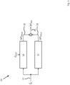
- Fig. 1 shows a graphical representation of a wind energy conversion system 10, an electric power system 11, and a system 12 for determining a setpoint signal.
- the wind energy conversion system 10 is electrically connected to the electric power system 11 and can for example be a wind power plant, a wind turbine, or a plurality of wind power plants or wind turbines.
- the electric power system 11 can transmit and / or distribute electric power. Electric power can be transferred between the wind energy conversion system 10 and the electric power system 11.
- the electric power system 11 comprises a system frequency (power (line) frequency), which has a target frequency value (nominal value) typically at 50 Hz or 60 Hz. Deviations in the system frequency are generally required to be within small limits around the target frequency value.
- the system 12 (wind integration processing element) is connected to the wind energy conversion system 10 and the electric power system 11. Signals can be transferred between each of the wind energy conversion system 10, the electric power system 11, and the system 12.
- the system 12 may be included in the wind energy conversion system 10.
- existing control units of the wind energy conversion system 10 may be slightly modified in order to implement the system 12, preferably without requiring additional hardware.
- the system 12 is separated from the wind energy conversion system 10.
- the system 12 comprises a first, a second, and a third signal processing device (13, 14, 15).
- Each of the first, the second, and the third signal processing device (13, 14, 15) can be a separate processor.
- the first, the second, and the third signal processing device (13, 14, 15) can be integrated in a single processor.
- Fig. 2 shows a graphical representation of a method for determining a setpoint signal 20 of the wind energy conversion system 10.
- Wind speed can comprise a characteristic spectrum.
- an output power fluctuation spectrum of the wind energy conversion system 10 and therefore also a spectrum of system frequency variations are expected to exhibit similar characteristics.
- a frequency spectrum of the wind speed comprises a low-frequency component and a turbulence component.
- the turbulence component corresponds to fast fluctuations around a quasi-steady mean wind speed.
- the method may employ the spectrum of the system frequency variations for mitigating periodic system frequency variations.
- the method can also mitigate aperiodic system frequency variations caused by aperiodic unscheduled changes of electric power. Both methods utilize the kinetic energy stored in the rotating mass of the WECS.
- a frequency spectrum of the system frequency variations of the electric power system is determined. If the electric power system comprises a large share of wind power, the spectrum is expected to be dominated by specific frequency components. As the dominating frequency components may change during operation, the method enables keeping track of the dominating frequency components via online spectral analysis. As a result, the periodic system frequency deviations with dominating magnitudes are mitigated and kept within a narrow band. Moreover, determining points of maximum power extraction of the wind energy conversion system 10 (maximum power point tracking, MPPT) can still be carried out effectively.
- MPPT maximum power point tracking
- the method also addresses aperiodic system frequency variations that are characterized by a large rate of change of frequency.
- the setpoint signal 20 determined by the method serves for setting an output power ue P e,ref of the wind energy conversion system 10.
- the setpoint signal 20 further facilitates mitigating the system frequency variations of the electric power system 11 while simultaneously meeting two requirements: maximization of wind power capture and operation within rotational speed limits and power limits of the wind energy conversion system 10.
- the system 12 is provided with a first and a second input signal (21, 22) from measurements and comprises a first, a second, and a third module (23, 24, 25), which may be implemented in a shared signal processing device or, alternatively, in the first, second, and third signal processing device (13, 14, 15), respectively.
- the first input signal 21 comprises (power) system frequency values f g and the second input signal 22 comprises (at least) one angular speed value ⁇ e of the rotor of the wind energy conversion system 10.
- the first module serving as a frequency-dependent power compensator, is configured to mitigate the system frequency variations by determining a power correction signal 26 comprising a first power value ⁇ P kin in order to either store or release kinetic energy in the rotating mass of the WECS.
- the second module 24 provides a first reference signal 27 comprising a second power ue P e,MPP,ref , representing an estimate for a maximally extractable power from wind, and a second reference signal 28 comprising an optimum angular speed value ⁇ e,MPP,ref , representing an estimate for a corresponding optimum angular speed. Both estimates correspond to a point of maximum power extraction (maximum power point, MPP). Hence, the second module 24 serves as an MPP estimator. The estimate of the maximum extractable power from wind is required in order to mitigate the system frequency variations while operating around the MPP.
- the second module 24 receives the second input signal 22 comprising the angular speed values ⁇ e .
- the second module 24 further receives a power feedback signal 29 comprising a third power value ⁇ P e,ref,add .
- the third power value ⁇ P e,ref,add corresponds to a difference of the output power value P e,ref and the second power value P e,MPP,ref .
- the third power value ⁇ P e,ref,add describes a value of additional electric power that is demanded when mitigating the system frequency deviation at a particular time.
- the first power value ⁇ P kin of the power correction signal 26 and second power ue P e,MPP,ref of the first reference signal 27 are added, resulting in an optimal power ue P opt .
- the optimal power value P opt is optimal in the sense that a maximum of wind power is captured and system frequency variations are mitigated, but operational limits of the wind energy conversion system 10 are yet neglected.
- the third module 25 provides the setpoint signal 20 for setting the output power value P e,ref of the wind energy conversion system 10 and assists in ensuring that the wind energy conversion system 10 operates within a defined safe operating region by requiring that angular speed limits and power limits of the wind energy conversion system 10 are respected.
- a fluctuating feed-in of wind power will cause periodic system frequency variations around the (nominal) target frequency value f nom .
- the periodic system frequency variations / oscillations of the system frequency f g around f nom are due to turbulence components of the wind speed. Beyond the periodic frequency variations, the system frequency f g also exhibits aperiodic variations due to system disturbance..
- the periodic and aperiodic system frequency variations are mitigated by making use of the kinetic energy stored in the rotating mass of the wind energy conversion system 10.
- Fig. 3 shows a graphical representation of the first module 23.
- the first module 23 comprises a first submodule 30 and a second submodule 31, each of which may be implemented in a respective separate or a shared signal processing device.
- the first input signal 21 is fed to both the first and the second submodule 30, 31.
- the first submodule 30 is configured to filter the first input signal 21 so as to mitigate the periodic frequency variations, while the second submodule 31 is configured to filter the first input signal 21 so as to mitigate the aperiodic frequency variations.
- the first submodule 30 generates a periodic power correction signal 32 comprising a filtered periodic power value ⁇ P kin,p .
- the second submodule 31 generates an aperiodic power correction signal 33 comprising a filtered aperiodic power value ⁇ P kin,a .
- the filtered periodic power value ⁇ P kin,p of the periodic power correction signal 32 and the filtered aperiodic power value ⁇ P kin,a of the aperiodic power correction signal 33 are added, yielding the first power value ⁇ P kin of the power correction signal 26.
- the first submodule 30 and / or the second submodule 31 may be activated or deactivated.
- FIG. 4a shows a graphical representation of an exemplary time evolution of system frequency values f g .
- a first curve 40 comprises the system frequency values f g depending on time t.
- the shown system frequency values f g have been measured by a phase locked loop at a point of common coupling of an exemplary grid connected wind energy conversion system 10, employing a power system model based on the Irish power transmission system, which has been adapted according to a future energy scenario in 2040.
- the energy scenario comprises a system penetration level of power electronic (PE) interfaced sources around 90 %, of which 65 % is supplied by wind, thus offering a challenging context in terms of system frequency variations. No method for mitigating the system frequency variations has been employed for obtaining the first curve 40.
- PE power electronic
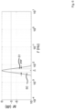
- Fig. 4b shows the spectrum of the system frequency deviation values ⁇ f g for the energy scenario with 90 % PE system penetration level.
- the spectrum as represented by a second curve 41 is obtained employing a fast Fourier transform / FFT for a time interval of 10 minutes.
- the second curve 41 comprises magnitudes
- Distinctive frequency components f with large magnitudes (amplitudes) appear within a wind turbulence frequency range, e.g., at a maximum peak around 4.5 mHz.
- the first submodule 30 is configured to identify frequency bands of dominating frequency components. This is supported by filtering.
- Fig. 5 shows a graphical representation of the first submodule 30. From the first input signal 21 comprising the system frequency values f g an intermediate signal 50 comprising the system frequency deviation values ⁇ f g is determined by subtracting the system frequency values f g from the target frequency value f nom .
- the first submodule comprises a frequency band identifying unit 51 and a plurality of band-pass filter units 52.
- Each of the band-pass filter units is assigned to one of the frequency bands identified by the frequency band identifying unit 51.
- the frequency band identifying unit 51 determines one of a plurality of filter settings 53.
- each of the filter settings 53 is transmitted to one of the band-bass filter units 52.
- the band-pass filter units 52 are tuned according to the respective filter settings 53 comprising the determined frequency bands and correspondingly filter the intermediate signal 50, resulting in partial signals 54.
- Each of the band-pass filter units 52 passes only the assigned determined frequency band of the intermediate signal 50 and attenuates remaining frequency components outside the determined frequency band.
- the number of band-pass filter units 52 is variable and can be chosen, e.g., depending on characteristics of the first input signal 21.
- the spectrum shown in Fig. 4b comprises two dominating frequency components 42, 43 at 2 mHz and 4.5 mHz, respectively.
- two band-pass filter units 52 should be employed.
- alternative selections can be made.
- the frequency band identifying unit 51 is configured to determine the number of dominating frequency components. From the number of dominating frequency components, a number of activated band-pass filter units 52 is determined.
- the partial signals 54 are subsequently summed up, yielding a first filtered signal 55.
- the periodic power signal 32 comprising the filtered periodic power value ⁇ P kin,p is determined.
- the filtered periodic power value ⁇ P kin,p corresponds to a portion of rotor kinetic energy utilized for the periodic mitigating of the system frequency variations.
- performance of the submodule 30 in mitigating the periodic frequency variations is increased.
- Each of the band-pass filter units 52 is characterized by its passband and can be implemented in different ways, for example as a finite impulse response filter (FIR) or an infinite impulse response filter (IIR).
- the IIR filter provides a smaller filter size for a corresponding filter specification in comparison with the FIR filter.
- the filter size being smaller corresponds to fewer required arithmetic operations and a lower signal delay. Minimizing the signal delay is particularly important for counteracting the periodic frequency variations in time. Hence, employing the IIR filter may here be preferable.
- Designing the IIR filter comprises determining the IIR filter coefficients in order to meet desired frequency response specifications. Determining the IIR filter coefficients can be based on an analog filter prototype. For this, a second transfer function G a of an analog filter in the s-domain is transformed into the transfer function G of the corresponding digital IIR filter in the z-domain.
- the passband bandwidth BW is identified by dashed lines 60, 61, where the magnitude M of G a ( s ) is equal to -3 dB.
- the second transfer function G a can be transformed to the transfer function G by for example applying a bilinear transform on the second transfer function G a .
- the band-pass filter units 52 can be tuned manually or automatically. If tuned manually, parameters of the band-pass filter units 52 are set to handle the dominating frequency components that are expected at certain frequency ranges. Continuous online changes of the dominant frequency components may be tracked through automatic tuning. Online tracking of the dominant frequency components is performed using the frequency band identifying unit 51. Automatic online tuning of the band-pass filter units 52 may be performed as follows.
- Fig. 7 shows a graphical representation of the automatic online tuning of each the band-pass filter units 52 by determining the respective center frequency f r .
- three exemplary time windows 70, 71, 72 with window size W are determined for updating of the center frequency f r .
- the window size W determines a first time interval over which the spectrum of the frequency deviations is calculated.
- the step size ⁇ t represents a second time interval between ending times of two successive time windows 70, 71, 72.
- Each of the time windows 70, 71, 72 is specified by its ending time t 3 , t 4 , and t 5 , respectively.
- the spectrum of the system frequency deviation values ⁇ f g appearing in the corresponding time window 70, 71, 72 is determined by applying an FFT on the system frequency deviation values ⁇ f g in the corresponding time window 70, 71, 72. Since the FFT is performed at the respective ending times t 3 , t 4 , and t 5 , a third time interval between two consecutive FFT calculations is also given by ⁇ t.
- the step size ⁇ t may for example be 1 minute and the window size W may be 10 minutes.
- the determined spectrum is analyzed to determine the dominating frequency components, i.e., the frequency components with largest magnitudes.
- an i -th center frequency f r, i of the i -th of the band-pass filter units 52 is updated after every FFT calculation, i.e., after passing in time the step size ⁇ t.
- an i -th magnitude of an i -th spectrum at f dom, i is compared with a predefined spectrum threshold value. If the i-th magnitude of the i-th spectrum exceeds the spectrum threshold value, the i-i -th center frequency f r, i is changed and set equal to the dominant frequency nent f dom, i .
- the i-th center frequency f r, i is left unchanged. This is because a current setting of i-th center frequency f r, i provides sufficient damping of i -th dominant frequency component f dom, i .
- the band-pass filter units 52 operate with the updated i -th center frequencies f r, i until the next FFT calculation is performed.
- Fig. 8 shows a graphical representation of the second submodule 31.
- aperiodic system frequency variations can be addressed.
- the aperiodic signal processor 31 can provide frequency support proportional to the ROCOF in order to mitigate the aperiodic system frequency variations due to system disturbance.
- the first input signal 21 is filtered by a high-pass filter 81 with time constant ⁇ in and subsequently fed into a deadband 82, resulting in a second filtered signal 83.
- the second filtered signal is multiplied with the first input signal 21.
- the high-pass filter 81 can integrate a differentiator and a subsequent low-pass filter on the first input signal 21. Differentiating the first input signal 21 with the system frequency values f g , a rate of change of the system frequency values f g is obtained, which represents the ROCOF.
- the low-pass filtering reduces effects from measurement noise arising from the differentiating of the first input signal 21. With the deadband 82, a given amplitude of the ROCOF is tolerated.
- the deadband 82 generates a zero output for inputs within its selected deadband.
- the deadband 82 may be adjustable. Delay times of the low-pass filter, indicated by ⁇ in , can be between 50 ms and 500 ms.
- the differentiator and the low pass filter can be combined into one transfer function.
- the resulting transfer function is a high pass filter.
- the time constant ⁇ in is associated with the low-pass filter.
- a response of the second submodule 31 can be enhanced by increasing a second gain parameter K aper of a second gain 84.
- the second gain 84 provides the aperiodic power correction signal 33 comprising the filtered aperiodic power value ⁇ P kin,a .
- the second module 24 provides the second power value P e,MPP,ref , representing the estimate for the maximally extractable power from wind, and the optimum angular speed value ⁇ e,MPP,ref , representing the estimate for the corresponding optimum angular speed.
- the second power value P e,MPP,ref and the optimum angular speed value ⁇ e,MPP,ref are determined as follows.
- Fig. 9 shows a typical relation of the power coefficient C P ( ⁇ ) and the tip speed ratio ⁇ , represented by a third curve 90.
- ⁇ CPmax 2 ⁇ e , MPP r pV w
- the wind speed V w is considered as given
- ⁇ e,MPP denotes a corresponding steady-state optimal angular speed of the rotor.
- P tur,max 1 2 ⁇ r 2 V w 3 C P ⁇ CPmax .
- Eq. (6) also models a maximum electric output power P e,MPP
- the optimum angular speed value ⁇ e,MPP,ref may be determined, as done in existing maximum power point trackers, by measuring the angular speed value ⁇ e . This way, however, the effect of a change of electric output power, ⁇ P e,add , and a change of mechanical turbine power, ⁇ P tur,add , on the angular speed value ⁇ e are not accounted for. In contrast, the optimum angular speed value ⁇ e,MPP,ref may also be determined as follows.
- the change of electrical output power ⁇ P e,add in Eq. (13) can readily be estimated from the third power value ⁇ P e,add,ref , which is also a second module input (cf. Fig. 2 ).
- the third power value ⁇ P e,add,ref further being a reference control signal
- an action on the change of electric output power ⁇ P e,add is delayed depending on a design of a power control loop.
- the change of mechanical turbine power ⁇ P tur,add is obtained by a dedicated calculator that uses a present measurement of the angular speed value ⁇ e and the optimum angular speed value ⁇ e,MPP,ref as inputs for the change of mechanical turbine power ⁇ P tur,add .
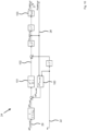
- Fig. 10 shows a graphical representation of the second module 24. Representing Eq. (11) to Eq. (14) in the Laplace domain (s-domain) allows in particular for a transfer function representation of the second module 24. Calculating the change of mechanical turbine er ⁇ P tur,add is optional. Still, as shown by simulations MPP tracking accuracy is improved and, in turn, mitigating of system frequency deviations.
- the second input signal 22 comprising the angular speed value ⁇ e and the power feedback signal 29 comprising the third power value ⁇ P e,ref,add are provided.
- the change of electrical output power ⁇ P e,add is determined from the third power value ⁇ P e,ref,add .
- the change of mechanical turbine power ⁇ P tur,add is determined from the angular speed value ⁇ e by a change of power calculator 100. In case the change of mechanical turbine power ⁇ P tur,add has been determined, the change of electrical output power ⁇ P e,add and the change of mechanical turbine power ⁇ P tur,add are added.
- the change of electrical output power ⁇ P e,add (or a sum of the change of electrical output power ⁇ P e,add and the change of mechanical turbine power ⁇ P tur,add ) are integrated by an integrator 101, yielding an integrated signal 102 comprising an integrated value.
- the integrated value may be represented as p 2 / 2 J ⁇ t 0 t ⁇ P e , add ⁇ + ⁇ P tur , add ⁇ d ⁇ .
- the integrated value is added to a squared value of the angular speed value ⁇ e and subsequently subjected to a square root, yielding the second reference signal 28 comprising the optimal angular speed value ⁇ e,MPP,ref .
- Raising the optimal angular speed value ⁇ e,MPP,ref to the power of 3 and applying a third gain 103 with a third gain parameter K MPP yields the first reference signal 27 comprising the second power value P e,MPP,ref .
- Fig. 11 shows a graphical representation of the mechanical turbine power P tur depending on the angular speed value ⁇ e .
- Eq. (15) is represented by a fourth curve 110 shown in Fig. 11 .
- the mechanical turbine power P tur is modelled by replacing C P ( ⁇ ) with C P2 ( ⁇ ) in Eq. (15) and then replacing the tip speed ratio ⁇ by 2 ⁇ e r / pV w (cf. Eq. (3)):
- P tur 2 1 2 ⁇ r 2 c 0 , p V w 3 + 2 c 1 , p r p V w 2 ⁇ e + 2 c 2 , p r 2 p 2 V w ⁇ e 2 , with the approximated mechanical turbine power P tur2 .
- Eq. (17) with approximating the power coefficient C P ( ⁇ ) around the optimal tip speed ratio ⁇ CPmax (cf. Fig. 9 ) is represented by a fifth curve 111.
- the mechanical turbine power P tur and the approximated mechanical turbine power P tur2 are almost equal for small variations around the steady-state operating point.
- the change of mechanical turbine power ⁇ P tur,add can be determined based on the approximated turbine power P tur2 .
- Eq. (17) is considered as a quadratic function of the angular speed value ⁇ e .
- a vertex 112 of the quadratic function is located at a point ( ⁇ e ( t 0 ), P tur2 ( t 0 )).
- Fig. 12 shows a graphical representation of the change of power calculator 100 for determining the change in mechanical turbine power ⁇ P add,tur .
- the change of power calculator 100 implements Eq. (26).
- the change in mechanical turbine power ⁇ P add,tur is determined from angular speed value ⁇ e of the second input signal 22 and the optimum angular speed value ⁇ e,MPP,ref of the second reference signal 28.
- the method for determining the setpoint signal 20 has to maintain stability of the wind energy conversion system 10 for all times.
- the output power value P e,ref of the setpoint signal 20 must adhere to corresponding stability limits.
- the frequency-dependent first power value ⁇ P kin is positive and the output power value P e,ref is temporarily larger than P e,MPP
- (d ⁇ e / d t) 0 with d ⁇ e / dt ⁇ 0. This entails a deceleration of the rotating mass of the rotor.
- Fig. 13a shows a graphical representation of a torque coefficient C T depending on the tip speed ratio ⁇ .
- a tip speed ratio lower limit ⁇ min is defined with ⁇ min > ⁇ CTmax and constitutes a lower limit for the tip speed ratio ⁇ .
- the angular speed value ⁇ e should not surpass an upper angular speed it ⁇ e,max due to mechanical constraints. Consequently, the angular speed value ⁇ e adheres to stability constraints represented by: ⁇ e , min ⁇ ⁇ e ⁇ ⁇ e , max .
- Providing an optimal power value P opt which is equal to P e,MPP,ref + ⁇ P kin , does not yet account for the stability constraints. If the output power value P e,ref would be set equal to the optimal power value P opt , then a corresponding operating point may lie outside the stability constraints. In order to comply with the stability constraints, the output power value P e,ref may have to be adapted. In case of ⁇ e ⁇ ⁇ e,MPP,ref , the output power value P e,ref is reduced to a specific percentage of the optimal power value P opt , depending on the deviation of the angular speed value ⁇ e from the optimum angular speed value ⁇ e,MPP,rer .
- the optimal power value P opt is retained. Increasing the output power value P e,ref above the optimal power value P opt in this case could result in a desired reduction of rotor speed, but could also result in excess power to the electric power system 11 in times of oversupply indicated by an over-frequency condition. Therefore, limiting increased rotor speeds to the upper angular speed limit ⁇ e,max by means of pitch angle control is preferred if no other energy storage is available.
- Fig. 13b shows a graphical representation for an exemplary embodiment to account for the stability constraints.
- the output power value P e,ref as a function of the angular speed value ⁇ e is represented by a sixth curve 132.
- the third module 25 sets the output power value P e,ref to a certain percentage of the optimal power value P opt . If the angular speed value ⁇ e drops below the optimum angular speed value ⁇ e,MPP,ref , the output power value P e,ref is reduced by a cubic root relation that reflects a cubic relation of angular speed and power.
- the output power value P e,ref is set to a minimum power value P min .
- the minimum power value P min may be 0 W. Other values may be set, for example depending on applicable grid codes.
- the minimum power value P min is only reached temporarily, if at all, as the rotor quickly regains angular speed by the reduction of the output power value P e,ref to a small fraction of the optimal power value P opt . If the angular speed value ⁇ e rises above optimum angular speed value ⁇ e,MPP,ref , the third module 25 retains P opt for output power value P e,ref .
- the effectiveness of the method in mitigating the system frequency variations is validated by means of implementation in the simulation software PowerFactory DIgSILENT.
- a nonlinear dynamic system model based on the transmission system of Ireland that was adjusted to specifications of a future energy scenario for 2040 has been employed.
- the system penetration level from power electronic interfaced sources is around 90 %, of which 65 % is supplied by wind farms.
- the employed wind energy conversion system model represents a nonlinear WECS, modelling a rated power of 3 MW that is reached at a nominal wind speed of 12 m / s.
- Wind turbines are grouped into 35 onshore wind farms and four offshore wind farms of different sizes.
- the performance of the method is assessed by comparing the simulation results of two scenarios.
- a first scenario all wind turbines within a wind farm are assumed to operate in a maximum power point tracking (MPPT) mode. The results are expected to describe a situation with large system frequency variations caused by wind farms since the WECS are not participating in the mitigation of the frequency variations.
- MPPT maximum power point tracking
- the method is implemented in a WECS model. Here, two second order band-pass filters are utilized.
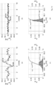
- Fig. 14a shows a graphical representation of a first system frequency time evolution in case of standard MPPT operation
- Fig. 14b shows a graphical representation of a second system frequency time evolution in case of operation according to the proposed method.
- the system frequency variations are substantially reduced.
- Fig. 14c shows a graphical representation of a first system frequency distribution with a first normalized histogram 140 and a first empirical distribution function 141 of the first system frequency time evolution shown in Fig. 14a.
- Fig. 14d shows a graphical representation of a second system frequency distribution with a second normalized histogram 142 and a second empirical distribution function 143 of the second system frequency time evolution shown in Fig. 14b .
- the first system frequency distribution comprises a first standard deviation of 46.2 mHz
- the second system frequency distribution comprises a second standard deviation of only 15.4 mHz. This corresponds to a 66.7% reduction of the first standard deviation.
- Fig. 15a shows a graphical representation of a first spectrum of system frequency deviations of the first system frequency time evolution.
- Fig. 15a shows a graphical representation of a second spectrum of system frequency deviations of the second system frequency time evolution.
- Fig. 15c shows a graphical representation of a third system frequency time evolution in case of standard MPPT operation
Landscapes
- Engineering & Computer Science (AREA)
- Life Sciences & Earth Sciences (AREA)
- Sustainable Development (AREA)
- Sustainable Energy (AREA)
- Chemical & Material Sciences (AREA)
- Combustion & Propulsion (AREA)
- Mechanical Engineering (AREA)
- General Engineering & Computer Science (AREA)
- Control Of Eletrric Generators (AREA)
Claims (11)
- Verfahren zur Bestimmung eines Sollwertsignals (20) eines Windenergieumwandlungssystems (10), wobei das Verfahren in einem mindestens eine Signalverarbeitungsvorrichtung (13, 14, 15) aufweisenden System (12) Folgendes umfasst:- Vorsehen eines ersten Eingangssignals (21), das Systemfrequenzwerte eines elektrischen Leistungssystems (11) umfasst, und eines zweiten Eingangssignals (22), das einen Winkelgeschwindigkeitswert eines Windenergieumwandlungssystems (10) umfasst;- Bestimmen, aus dem ersten Eingangssignal (21), eines Zwischensignals (50), das Abweichungswerte der Systemfrequenz umfasst, wobei die Abweichungswerte der Systemfrequenz Abweichungen zwischen den Systemfrequenzwerten und einem Zielfrequenzwert anzeigen;- Bestimmen, aus dem Zwischensignal (50) und dem ersten Eingangssignal (21), eines Leistungskorrektursignals (26), das einen ersten Leistungswert umfasst;- Bestimmen, aus dem zweiten Eingangssignal (22), eines ersten Referenzsignals (27), das einen zweiten Leistungswert entsprechend einem Punkt von maximaler Leistungsentnahme des Windenergieumwandlungssystems (10) umfasst;- Bestimmen, aus dem Leistungskorrektursignal (26) und dem ersten Referenzsignal (27), eines Sollwertsignals (20) zum Einstellen eines Ausgangsleistungswerts des Windenergieumwandlungssystems (10); und- Speichern oder Freigeben von kinetischer Energie in der drehenden Masse des Windenergieumwandlungssystems (10) auf Basis des ersten Leistungswerts des Leistungskorrektursignals (26);wobei das Bestimmen des Leistungskorrektursignals Folgendes umfasst:- Identifizieren von Frequenzbändern von dominierenden Frequenzkomponenten in dem Zwischensignal (50);- Bestimmen der Anzahl der dominierenden Frequenzkomponenten;- Bestimmen einer Anzahl von aktivierten Bandpass-Filtereinheiten (52) aus der Anzahl der dominierenden Frequenzkomponenten;- Verwenden der aktivierten Bandpass-Filtereinheiten (52) zum Filtern des Zwischensignals (50), was in Teilsignalen (54) resultiert;- Aufsummieren der Teilsignale (50), um den ersten Leistungswert zu ergeben.
- Verfahren nach Anspruch 1, wobei das Filtern unter Verwendung eines Filters mit unendlicher Impulsantwort ausgeführt wird.
- Verfahren nach Anspruch 1 oder 2, weiterhin umfassend das Bestimmen von aperiodischen Systemfrequenzabweichungen aus dem ersten Eingangssignal (21).
- Verfahren nach mindestens einem der vorstehenden Ansprüche, weiterhin umfassend das Bestimmen, aus dem ersten Eingangssignal (21), eines zweiten gefilterten Signals (83) durch Filtern des ersten Eingangssignals (21).
- Verfahren nach Anspruch 4, wobei das Bestimmen des zweiten gefilterten Signals (83) weiterhin mindestens eines von Folgenden umfasst: Differenzieren des ersten Eingangssignals (21), Tiefpassfiltern des ersten Eingangssignals (21) und Anwenden eines Totbands (82) auf das erste Eingangssignal (21).
- Verfahren nach mindestens einem der vorstehenden Ansprüche, wobei das Bestimmen des ersten Referenzsignals (27) weiterhin das Bestimmen einer Änderung der elektrischen Ausgangsleistung umfasst.
- Verfahren nach mindestens einem der vorstehenden Ansprüche, weiterhin umfassend das Bestimmen, aus dem zweiten Eingangssignal (22), eines zweiten Referenzsignals (28), das einen optimalen Winkelgeschwindigkeitswert entsprechend dem Punkt der maximalen Leistungsentnahme des Windenergieumwandlungssystems (10) umfasst.
- Verfahren nach Anspruch 7, wobei das Bestimmen des ersten Referenzsignals (27) weiterhin das Bestimmen einer Änderung der mechanischen Turbinenleistung umfasst.
- Verfahren nach mindestens einem der vorstehenden Ansprüche, wobei das Bestimmen des Sollwertsignals (20) das Bestimmen eines optimalen Leistungswerts aus dem Leistungskorrektursignal (26) und dem ersten Referenzsignal (27) und das Ändern des optimalen Leistungswerts in Abhängigkeit von dem Winkelgeschwindigkeitswert des Windenergieumwandlungssystems (10) umfasst.
- Verfahren nach Anspruch 7 oder 8, wobei der optimale Leistungswert einer Abnahme unterliegt, wenn der Winkelgeschwindigkeitswert des Windenergieumwandlungssystems (10) kleiner als der optimale Winkelgeschwindigkeitswert ist.
- System (12) zur Bestimmung eines Sollwertsignals (20) eines Windenergieumwandlungssystems (10), das mindestens eine Signalverarbeitungsvorrichtung (13, 14, 15) umfasst, wobei die mindestens eine Signalverarbeitungsvorrichtung (13, 14, 15) eingerichtet ist, das Verfahren nach mindestens einem der vorstehenden Ansprüche auszuführen.
Priority Applications (3)
| Application Number | Priority Date | Filing Date | Title |
|---|---|---|---|
| EP20216978.5A EP4019768B1 (de) | 2020-12-23 | 2020-12-23 | Verfahren und system zur bestimmung eines sollwertsignals eines windenergieumwandlungssystems |
| US18/267,879 US12607164B2 (en) | 2020-12-23 | 2021-12-17 | Method and system for determining a setpoint signal of a wind energy conversion system |
| PCT/EP2021/086435 WO2022136156A1 (en) | 2020-12-23 | 2021-12-17 | Method and system for determining a setpoint signal of a wind energy conversion system |
Applications Claiming Priority (1)
| Application Number | Priority Date | Filing Date | Title |
|---|---|---|---|
| EP20216978.5A EP4019768B1 (de) | 2020-12-23 | 2020-12-23 | Verfahren und system zur bestimmung eines sollwertsignals eines windenergieumwandlungssystems |
Publications (2)
| Publication Number | Publication Date |
|---|---|
| EP4019768A1 EP4019768A1 (de) | 2022-06-29 |
| EP4019768B1 true EP4019768B1 (de) | 2025-01-29 |
Family
ID=73857092
Family Applications (1)
| Application Number | Title | Priority Date | Filing Date |
|---|---|---|---|
| EP20216978.5A Active EP4019768B1 (de) | 2020-12-23 | 2020-12-23 | Verfahren und system zur bestimmung eines sollwertsignals eines windenergieumwandlungssystems |
Country Status (3)
| Country | Link |
|---|---|
| US (1) | US12607164B2 (de) |
| EP (1) | EP4019768B1 (de) |
| WO (1) | WO2022136156A1 (de) |
Families Citing this family (3)
| Publication number | Priority date | Publication date | Assignee | Title |
|---|---|---|---|---|
| ES3037013T3 (en) * | 2020-11-13 | 2025-09-26 | Vestas Wind Sys As | Controlling a power plant comprising wind turbines during grid frequency deviation |
| US12586594B2 (en) * | 2022-09-22 | 2026-03-24 | Google Llc | Guiding ambisonic audio compression by deconvolving long window frequency analysis |
| CN120292014B (zh) * | 2025-05-28 | 2025-09-05 | 内蒙古明阳北方智慧能源研发中心有限公司 | 发电风机叶尖速比寻优控制方法与系统 |
Citations (2)
| Publication number | Priority date | Publication date | Assignee | Title |
|---|---|---|---|---|
| WO2020031085A1 (en) * | 2018-08-07 | 2020-02-13 | Universita' Degli Studi Di Genova | Method and system for controlling non-inertial generators, in particular wind generators, by inertia emulation |
| EP3400384B1 (de) * | 2016-01-06 | 2021-03-31 | Vestas Wind Systems A/S | Steuerung einer windkraftanlage |
Family Cites Families (11)
| Publication number | Priority date | Publication date | Assignee | Title |
|---|---|---|---|---|
| JP4106624B2 (ja) * | 2001-06-29 | 2008-06-25 | 株式会社ケンウッド | 信号の周波数成分を補間するための装置および方法 |
| CN101680428B (zh) * | 2007-04-30 | 2012-05-09 | 维斯塔斯风力系统有限公司 | 具有对于变化的转子速度受到补偿的双馈感应发电机的可变速度风力涡轮机 |
| US9478987B2 (en) * | 2009-11-10 | 2016-10-25 | Siemens Aktiengesellschaft | Power oscillation damping employing a full or partial conversion wind turbine |
| US8880357B2 (en) * | 2010-12-15 | 2014-11-04 | Kk-Electronic A/S | Apparatus for estimating a resonant frequency of a wind turbine tower |
| US10359473B2 (en) * | 2012-05-29 | 2019-07-23 | Nutech Ventures | Detecting faults in turbine generators |
| KR101450147B1 (ko) * | 2014-08-05 | 2014-10-13 | 전북대학교산학협력단 | 풍력발전기의 관성제어 방법 |
| US20160160839A1 (en) * | 2014-12-09 | 2016-06-09 | State Grid Corporation Of China | Method for controlling inertia response of variable-speed wind turbine generator |
| US9995307B2 (en) * | 2015-02-10 | 2018-06-12 | Kevin Allan Dooley Inc. | Two-way flow control device, associated systems and methods |
| US10024305B2 (en) * | 2015-11-10 | 2018-07-17 | General Electric Company | System and method for stabilizing a wind farm during one or more contingency events |
| JP6698715B2 (ja) * | 2018-01-23 | 2020-05-27 | 三菱重工業株式会社 | 設備状態監視装置および設備状態監視方法 |
| DE102018116445A1 (de) * | 2018-07-06 | 2020-01-09 | Wobben Properties Gmbh | Verfahren zum Erkennen niederfrequenter Schwingungen und Erfassungseinrichtung dafür |
-
2020
- 2020-12-23 EP EP20216978.5A patent/EP4019768B1/de active Active
-
2021
- 2021-12-17 US US18/267,879 patent/US12607164B2/en active Active
- 2021-12-17 WO PCT/EP2021/086435 patent/WO2022136156A1/en not_active Ceased
Patent Citations (2)
| Publication number | Priority date | Publication date | Assignee | Title |
|---|---|---|---|---|
| EP3400384B1 (de) * | 2016-01-06 | 2021-03-31 | Vestas Wind Systems A/S | Steuerung einer windkraftanlage |
| WO2020031085A1 (en) * | 2018-08-07 | 2020-02-13 | Universita' Degli Studi Di Genova | Method and system for controlling non-inertial generators, in particular wind generators, by inertia emulation |
Also Published As
| Publication number | Publication date |
|---|---|
| EP4019768A1 (de) | 2022-06-29 |
| US20240077059A1 (en) | 2024-03-07 |
| WO2022136156A1 (en) | 2022-06-30 |
| US12607164B2 (en) | 2026-04-21 |
Similar Documents
| Publication | Publication Date | Title |
|---|---|---|
| US12607164B2 (en) | Method and system for determining a setpoint signal of a wind energy conversion system | |
| CN101688518B (zh) | 可变速度风力涡轮机、谐振控制系统、运行可变速度风力涡轮机的方法、可变速度风力涡轮机中方法的使用以及谐振控制系统的使用 | |
| EP2115299B1 (de) | Windturbinendämpfung einer turmresonanzbewegung und symmetrischen schaufelbewegung unter verwendung von schätzungsverfahren | |
| CN114258459B (zh) | 利用叶片载荷信号减少沿边振动 | |
| US8688282B2 (en) | Method and system for controlling a wind power plant comprising a number of wind turbine generators | |
| CN101499766A (zh) | 发电稳定控制系统及方法 | |
| EP3861631B1 (de) | Verfahren und system von subsynchronen schwingungen und interaktionsdämpfung | |
| Kristalny et al. | On using wind speed preview to reduce wind turbine tower oscillations | |
| WO2020239178A1 (en) | Reduction of edgewise vibrations using torsional vibration signal | |
| EP2113659B1 (de) | Verfahren zum Betreiben einer Windturbine zur Minimierung der Schwingungen des Turms | |
| WO2016004950A1 (en) | Active promotion of wind turbine tower oscillations | |
| EP4148509A1 (de) | Modellbasiertes prädiktives steuerungsverfahren zur strukturellen lastreduzierung in windturbinen | |
| CN102334276B (zh) | 用于调节双馈异步电机的装置 | |
| CN111342465B (zh) | 一种主动抑制电力系统频率波动的虚拟滤波器设计方法 | |
| CN107580660A (zh) | 用于运行风能设备的方法 | |
| Thiringer et al. | Control of a variable-speed pitch-regulated wind turbine | |
| Lao et al. | Novel insight on temporary frequency support of variable speed wind energy conversion system | |
| Farmer et al. | Modelling a wind turbine as a low-pass filter for wind to electrical power calculations | |
| US12180937B2 (en) | Wind turbine control for drivetrain load variations | |
| WO2023126043A1 (en) | Torque limiter based on current torque value | |
| Perrone et al. | Offshore wind turbine tower fore-aft fatigue load reduction by coupling control and vibrational analysis | |
| Bourlis et al. | Gain scheduled controller with wind speed estimation via Kalman filtering for a stall regulated variable speed wind turbine | |
| Beloki et al. | Application of Digital State Variable Filters for Resonance Mitigation on a Wind Turbine Torque Control with Finite Precision | |
| Lee et al. | RoCoF Threshold-Based Gain Scheduling for FFR Implementation in High Renewable Power Systems | |
| WO2024120596A1 (en) | Dertermining wind speed at a wind turbine |
Legal Events
| Date | Code | Title | Description |
|---|---|---|---|
| PUAI | Public reference made under article 153(3) epc to a published international application that has entered the european phase |
Free format text: ORIGINAL CODE: 0009012 |
|
| STAA | Information on the status of an ep patent application or granted ep patent |
Free format text: STATUS: THE APPLICATION HAS BEEN PUBLISHED |
|
| AK | Designated contracting states |
Kind code of ref document: A1 Designated state(s): AL AT BE BG CH CY CZ DE DK EE ES FI FR GB GR HR HU IE IS IT LI LT LU LV MC MK MT NL NO PL PT RO RS SE SI SK SM TR |
|
| STAA | Information on the status of an ep patent application or granted ep patent |
Free format text: STATUS: REQUEST FOR EXAMINATION WAS MADE |
|
| 17P | Request for examination filed |
Effective date: 20221229 |
|
| RBV | Designated contracting states (corrected) |
Designated state(s): AL AT BE BG CH CY CZ DE DK EE ES FI FR GB GR HR HU IE IS IT LI LT LU LV MC MK MT NL NO PL PT RO RS SE SI SK SM TR |
|
| STAA | Information on the status of an ep patent application or granted ep patent |
Free format text: STATUS: EXAMINATION IS IN PROGRESS |
|
| 17Q | First examination report despatched |
Effective date: 20230210 |
|
| RIC1 | Information provided on ipc code assigned before grant |
Ipc: F03D 7/02 20060101AFI20240628BHEP |
|
| GRAP | Despatch of communication of intention to grant a patent |
Free format text: ORIGINAL CODE: EPIDOSNIGR1 |
|
| STAA | Information on the status of an ep patent application or granted ep patent |
Free format text: STATUS: GRANT OF PATENT IS INTENDED |
|
| INTG | Intention to grant announced |
Effective date: 20240902 |
|
| GRAS | Grant fee paid |
Free format text: ORIGINAL CODE: EPIDOSNIGR3 |
|
| GRAA | (expected) grant |
Free format text: ORIGINAL CODE: 0009210 |
|
| STAA | Information on the status of an ep patent application or granted ep patent |
Free format text: STATUS: THE PATENT HAS BEEN GRANTED |
|
| AK | Designated contracting states |
Kind code of ref document: B1 Designated state(s): AL AT BE BG CH CY CZ DE DK EE ES FI FR GB GR HR HU IE IS IT LI LT LU LV MC MK MT NL NO PL PT RO RS SE SI SK SM TR |
|
| REG | Reference to a national code |
Ref country code: GB Ref legal event code: FG4D |
|
| REG | Reference to a national code |
Ref country code: CH Ref legal event code: EP |
|
| REG | Reference to a national code |
Ref country code: DE Ref legal event code: R096 Ref document number: 602020045470 Country of ref document: DE |
|
| REG | Reference to a national code |
Ref country code: IE Ref legal event code: FG4D |
|
| REG | Reference to a national code |
Ref country code: NL Ref legal event code: MP Effective date: 20250129 |
|
| PG25 | Lapsed in a contracting state [announced via postgrant information from national office to epo] |
Ref country code: NL Free format text: LAPSE BECAUSE OF FAILURE TO SUBMIT A TRANSLATION OF THE DESCRIPTION OR TO PAY THE FEE WITHIN THE PRESCRIBED TIME-LIMIT Effective date: 20250129 |
|
| PG25 | Lapsed in a contracting state [announced via postgrant information from national office to epo] |
Ref country code: RS Free format text: LAPSE BECAUSE OF FAILURE TO SUBMIT A TRANSLATION OF THE DESCRIPTION OR TO PAY THE FEE WITHIN THE PRESCRIBED TIME-LIMIT Effective date: 20250429 |
|
| PG25 | Lapsed in a contracting state [announced via postgrant information from national office to epo] |
Ref country code: FI Free format text: LAPSE BECAUSE OF FAILURE TO SUBMIT A TRANSLATION OF THE DESCRIPTION OR TO PAY THE FEE WITHIN THE PRESCRIBED TIME-LIMIT Effective date: 20250129 |
|
| PG25 | Lapsed in a contracting state [announced via postgrant information from national office to epo] |
Ref country code: PL Free format text: LAPSE BECAUSE OF FAILURE TO SUBMIT A TRANSLATION OF THE DESCRIPTION OR TO PAY THE FEE WITHIN THE PRESCRIBED TIME-LIMIT Effective date: 20250129 |
|
| PG25 | Lapsed in a contracting state [announced via postgrant information from national office to epo] |
Ref country code: ES Free format text: LAPSE BECAUSE OF FAILURE TO SUBMIT A TRANSLATION OF THE DESCRIPTION OR TO PAY THE FEE WITHIN THE PRESCRIBED TIME-LIMIT Effective date: 20250129 |
|
| REG | Reference to a national code |
Ref country code: LT Ref legal event code: MG9D |
|
| PG25 | Lapsed in a contracting state [announced via postgrant information from national office to epo] |
Ref country code: NO Free format text: LAPSE BECAUSE OF FAILURE TO SUBMIT A TRANSLATION OF THE DESCRIPTION OR TO PAY THE FEE WITHIN THE PRESCRIBED TIME-LIMIT Effective date: 20250429 Ref country code: IS Free format text: LAPSE BECAUSE OF FAILURE TO SUBMIT A TRANSLATION OF THE DESCRIPTION OR TO PAY THE FEE WITHIN THE PRESCRIBED TIME-LIMIT Effective date: 20250529 |
|
| REG | Reference to a national code |
Ref country code: AT Ref legal event code: MK05 Ref document number: 1763662 Country of ref document: AT Kind code of ref document: T Effective date: 20250129 |
|
| PG25 | Lapsed in a contracting state [announced via postgrant information from national office to epo] |
Ref country code: HR Free format text: LAPSE BECAUSE OF FAILURE TO SUBMIT A TRANSLATION OF THE DESCRIPTION OR TO PAY THE FEE WITHIN THE PRESCRIBED TIME-LIMIT Effective date: 20250129 |
|
| PG25 | Lapsed in a contracting state [announced via postgrant information from national office to epo] |
Ref country code: PT Free format text: LAPSE BECAUSE OF FAILURE TO SUBMIT A TRANSLATION OF THE DESCRIPTION OR TO PAY THE FEE WITHIN THE PRESCRIBED TIME-LIMIT Effective date: 20250529 Ref country code: LV Free format text: LAPSE BECAUSE OF FAILURE TO SUBMIT A TRANSLATION OF THE DESCRIPTION OR TO PAY THE FEE WITHIN THE PRESCRIBED TIME-LIMIT Effective date: 20250129 |
|
| PG25 | Lapsed in a contracting state [announced via postgrant information from national office to epo] |
Ref country code: BG Free format text: LAPSE BECAUSE OF FAILURE TO SUBMIT A TRANSLATION OF THE DESCRIPTION OR TO PAY THE FEE WITHIN THE PRESCRIBED TIME-LIMIT Effective date: 20250129 Ref country code: GR Free format text: LAPSE BECAUSE OF FAILURE TO SUBMIT A TRANSLATION OF THE DESCRIPTION OR TO PAY THE FEE WITHIN THE PRESCRIBED TIME-LIMIT Effective date: 20250430 |
|
| PG25 | Lapsed in a contracting state [announced via postgrant information from national office to epo] |
Ref country code: AT Free format text: LAPSE BECAUSE OF FAILURE TO SUBMIT A TRANSLATION OF THE DESCRIPTION OR TO PAY THE FEE WITHIN THE PRESCRIBED TIME-LIMIT Effective date: 20250129 |
|
| PG25 | Lapsed in a contracting state [announced via postgrant information from national office to epo] |
Ref country code: SE Free format text: LAPSE BECAUSE OF FAILURE TO SUBMIT A TRANSLATION OF THE DESCRIPTION OR TO PAY THE FEE WITHIN THE PRESCRIBED TIME-LIMIT Effective date: 20250129 |
|
| PG25 | Lapsed in a contracting state [announced via postgrant information from national office to epo] |
Ref country code: SM Free format text: LAPSE BECAUSE OF FAILURE TO SUBMIT A TRANSLATION OF THE DESCRIPTION OR TO PAY THE FEE WITHIN THE PRESCRIBED TIME-LIMIT Effective date: 20250129 |
|
| PG25 | Lapsed in a contracting state [announced via postgrant information from national office to epo] |
Ref country code: DK Free format text: LAPSE BECAUSE OF FAILURE TO SUBMIT A TRANSLATION OF THE DESCRIPTION OR TO PAY THE FEE WITHIN THE PRESCRIBED TIME-LIMIT Effective date: 20250129 |
|
| PG25 | Lapsed in a contracting state [announced via postgrant information from national office to epo] |
Ref country code: IT Free format text: LAPSE BECAUSE OF FAILURE TO SUBMIT A TRANSLATION OF THE DESCRIPTION OR TO PAY THE FEE WITHIN THE PRESCRIBED TIME-LIMIT Effective date: 20250129 |
|
| PG25 | Lapsed in a contracting state [announced via postgrant information from national office to epo] |
Ref country code: CZ Free format text: LAPSE BECAUSE OF FAILURE TO SUBMIT A TRANSLATION OF THE DESCRIPTION OR TO PAY THE FEE WITHIN THE PRESCRIBED TIME-LIMIT Effective date: 20250129 Ref country code: EE Free format text: LAPSE BECAUSE OF FAILURE TO SUBMIT A TRANSLATION OF THE DESCRIPTION OR TO PAY THE FEE WITHIN THE PRESCRIBED TIME-LIMIT Effective date: 20250129 |
|
| PG25 | Lapsed in a contracting state [announced via postgrant information from national office to epo] |
Ref country code: RO Free format text: LAPSE BECAUSE OF FAILURE TO SUBMIT A TRANSLATION OF THE DESCRIPTION OR TO PAY THE FEE WITHIN THE PRESCRIBED TIME-LIMIT Effective date: 20250129 |
|
| PG25 | Lapsed in a contracting state [announced via postgrant information from national office to epo] |
Ref country code: SK Free format text: LAPSE BECAUSE OF FAILURE TO SUBMIT A TRANSLATION OF THE DESCRIPTION OR TO PAY THE FEE WITHIN THE PRESCRIBED TIME-LIMIT Effective date: 20250129 |
|
| REG | Reference to a national code |
Ref country code: DE Ref legal event code: R097 Ref document number: 602020045470 Country of ref document: DE |
|
| PLBE | No opposition filed within time limit |
Free format text: ORIGINAL CODE: 0009261 |
|
| STAA | Information on the status of an ep patent application or granted ep patent |
Free format text: STATUS: NO OPPOSITION FILED WITHIN TIME LIMIT |
|
| 26N | No opposition filed |
Effective date: 20251030 |
|
| PGFP | Annual fee paid to national office [announced via postgrant information from national office to epo] |
Ref country code: GB Payment date: 20251218 Year of fee payment: 6 |
|
| PGFP | Annual fee paid to national office [announced via postgrant information from national office to epo] |
Ref country code: FR Payment date: 20251218 Year of fee payment: 6 |
|
| PGFP | Annual fee paid to national office [announced via postgrant information from national office to epo] |
Ref country code: DE Payment date: 20251222 Year of fee payment: 6 |