EP3400832B1 - Outil d'assemblage et procédé d'assemblage d'un rail de guidage sur une pièce de mobilier moulé en plaque - Google Patents
Outil d'assemblage et procédé d'assemblage d'un rail de guidage sur une pièce de mobilier moulé en plaque Download PDFInfo
- Publication number
- EP3400832B1 EP3400832B1 EP18171585.5A EP18171585A EP3400832B1 EP 3400832 B1 EP3400832 B1 EP 3400832B1 EP 18171585 A EP18171585 A EP 18171585A EP 3400832 B1 EP3400832 B1 EP 3400832B1
- Authority
- EP
- European Patent Office
- Prior art keywords
- guide rail
- plate
- shaped
- furniture part
- assembly tool
- Prior art date
- Legal status (The legal status is an assumption and is not a legal conclusion. Google has not performed a legal analysis and makes no representation as to the accuracy of the status listed.)
- Active
Links
Images


Classifications
-
- A—HUMAN NECESSITIES
- A47—FURNITURE; DOMESTIC ARTICLES OR APPLIANCES; COFFEE MILLS; SPICE MILLS; SUCTION CLEANERS IN GENERAL
- A47B—TABLES; DESKS; OFFICE FURNITURE; CABINETS; DRAWERS; GENERAL DETAILS OF FURNITURE
- A47B88/00—Drawers for tables, cabinets or like furniture; Guides for drawers
- A47B88/40—Sliding drawers; Slides or guides therefor
- A47B88/423—Fastening devices for slides or guides
Definitions
- the present invention relates to an assembly tool for assembling a guide rail on a plate-shaped furniture part according to the preamble of claim 1 and a method for mounting a guide rail on a plate-shaped furniture part.
- positioning aids for guide rails in order to position them at a predetermined distance from an end edge of a plate-shaped furniture part.
- the guide rail can be placed on a contact surface of the positioning aid.
- the US2005 / 0102816 A1 discloses an assembly tool for assembling a metallic rail, wherein a magnet for holding the rail is provided on the assembly tool.
- the DE 20 2017 100 195 U1 discloses an apparatus for connecting shelves which has an elastic hook.
- the assembly tool comprises a molded body with at least one receptacle for fixing a guide rail and an angular contact section which can be placed against an end edge and a surface of the plate-shaped furniture part.
- At least two spaced-apart receptacles for fixing guide rails with a different profile cross section are preferably provided on the molded body.
- the assembly tool can, for example, fix both an upper guide rail to an upper floor and a lower guide rail to a floor of a piece of cupboard furniture.
- the assembly tool can be used more flexibly for different profile cross-sections.
- the guide rail can in each case be fixed in a clamped manner in or on a receptacle of the shaped body, for example by means of bendable locking webs or elastic elements which are provided on the receptacle.
- a spring element is provided, which is provided for the clamping fixation of the molded body on a plate-shaped furniture part.
- the assembly tool can be positioned together with the guide rail on the plate-shaped furniture part, and the fitter can then let go of the assembly tool and carry out the fastening of the guide rail.
- the spring element can be fixed to the molded body in different connection positions, so that the assembly tool can be used for plate-shaped furniture parts of different thicknesses or, if necessary, additional components, such as strips, can be positioned and held on the plate-shaped furniture part via the assembly tool, in order then to do so fix together with the guide rail on the plate-shaped furniture part.
- the spring element can have a foot section which can be inserted or inserted into different receptacles of the molded body in order to be able to carry out a simple alignment of the spring element.
- the spring element is formed integrally with the shaped body and can be separated from the shaped body by severing a predetermined breaking point, in order then to be mounted on the shaped body again at predetermined connecting positions. This facilitates the manufacture of the assembly tool, which can be produced in one piece with the molded body and the spring element, for example by injection molding or extrusion processes, in particular made of plastic.
- a handle opening or handle recess can be formed in the molded body so that a guide rail can then be securely gripped and handled.
- a guide rail is first fixed in or on a receptacle of a shaped body, and then an angular one To position the contact section on an end edge and a surface of a plate-shaped furniture part in order to then fix the guide rail on the plate-shaped furniture part.
- a spring element is provided on the molded body, which is applied to the plate-shaped furniture part on the side opposite the guide rail, so that the positioning of the guide rail can take place both on an underside and on an upper side of a plate-shaped furniture part in the installation position before then the fitter fixes the guide rail on the plate-shaped furniture part.
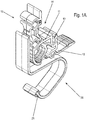
- An assembly tool 10 comprises a molded body 11 made of plastic, which can be produced, for example, by injection molding or extrusion.
- the molded body 11 comprises a first groove-shaped receptacle 12 for fixing a section of a guide rail in order to position it on a plate-shaped furniture part.
- a second groove-shaped receptacle 13 is provided for inserting a web of a guide rail, which is oriented at an angle to the first receptacle 12.
- An elongated wall section 17 is formed on the second receptacle 13, which serves as a latching web and has a groove-shaped receptacle 18, which can be latched on a web of a guide rail.
- the wall section 17 is also designed to be resilient on the molded body 11 in order to facilitate dismantling of the assembly tool 10 after fastening the rail 40 to the furniture body.
- an angular contact section 14 is also formed, which has a first leg 15 and a second leg 16 oriented at right angles thereto, which, in order to position a guide rail, which is held on one of the two receptacles 12 or 13, rest against a plate-shaped furniture part .
- the legs 15 or 16 can optionally rest over the entire surface of the plate-shaped furniture part or only over individual projections, in particular strip-shaped projections.
- the molded body 11 is formed integrally with a spring element 20, which is connected to the remaining molded body 11 via a predetermined breaking point 19.
- the spring element 20 comprises a foot section 21, which is at least section-wide wider than a curved web 22, which extends essentially in an arc or O-shape and has an angled contact section 23 on one leg.
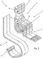
- FIG. 2 the assembly tool 10 is shown in a position in which the spring element 20, which is formed integrally with the molded body 11, has been separated from the latter at the predetermined breaking point 19.
- the fitter can now assemble the spring element 20 and the molded body 11 again, two receptacles 24 and 25 being formed on a rear side of the angular contact section 14, in particular on the leg 16, into which the foot section 21 can be inserted or inserted.
- a first receptacle 24 is located adjacent to the corner region of the angular contact section 14, and a second receptacle 25 in a central region of the leg 16.
- the spring element 20 according to FIG Figure 3 be mounted in the first receptacle 24 so that the contact section 23 is arranged at a short distance from the leg 15.
- the spring element 20 are fixed in the second receptacle 25, so that the curved contact section 23 is now arranged at a greater distance from the leg 15.
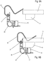
- the assembly tool 10 is shown in order to fix a guide rail 30 to a plate-shaped furniture part 5, for example a floor or top floor of a cupboard furniture.
- the guide rail 30 is angular in cross section, with one leg 31 inserted into the receptacle 12 and fixed there by clamping.
- the other leg of the guide rail 30 has a surface that is essentially flush with the leg 15.
- the assembly tool 10 can now together with the guide rail 30 according to Figure 5B be positioned such that the guide rail 30 is positioned and held on an underside of the plate-shaped furniture part 5 via the assembly tool 10.
- the distance of the guide rail 30 from the front end edge of the plate-shaped furniture part 5 is predetermined via the angular contact section 14.
- the assembly tool 10 is clamped together with the guide rail 30 to the plate-shaped furniture part 5, the curved shape of the spring element 20 being shown in the present application is not shown.
- the curved contact section 23 lies against the top of the plate-shaped furniture part 5, while the guide rail 30 is provided on the opposite underside of the plate-shaped furniture part 5.
- the assembly tool 10 is used to assemble a guide rail 30 which is on an upper side of a plate-shaped Furniture part 5 is to be mounted, which has a base 6 or another element on the underside.
- the spring element 20 cannot be used to encompass the plate-shaped furniture part 5 in a U-shape.
- the angular contact section can be placed against a front end edge of the plate-shaped furniture part 5 in order to position and then fix the guide rail 30, for example using screws, adhesive tapes or other fastening means .
- the guide rail 30 can be held over two assembly tools 10, each having a hollow handle opening 26.
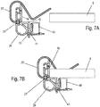
- a modified guide rail 40 is mounted on a plate-shaped furniture part 5.
- the guide rail 40 is U-shaped in cross section and has a section 41 which is inserted into the receptacle 13 on the molded body 11.
- the other leg which is designed as a vertical web, is inserted with an end face in the groove-shaped receptacle 18 on the wall section 17, so that the guide rail 40 is fixed in a clamped manner on the molded body 11.
- the guide rail 40 can now be similar to that in FIG Figure 5 be positioned on an underside of the plate-shaped furniture part 5, the spring element 20 ensuring that the assembly tool 10 is held clamped together with the guide rail 40 on the plate-shaped furniture part 5, so that the fitter now uses other fastening means to guide the guide rail 40 on the underside of the plate-shaped Furniture part 5 can fix.
- the assembly of the U-shaped guide rail 40 is shown, which is fixed to the receptacle 13 of the assembly tool 10.
- the guide rail 40 can also be clamped on the spring element 20 plate-shaped furniture part 5 are fixed with the strip 9, in order then to fix the guide rail 40 to the strip 9 by means of fastening means, the strip 9 optionally also being fixed together with the guide rail 40 on the plate-shaped furniture part 5.
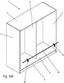
- FIGS Figures 5 and 6 the assembly of the guide rail 30 via two assembly tools 10 is shown, which hold the guide rail 30 at a distance from one another in order to fix it on a floor as a plate-shaped furniture part 5 of a cabinet-shaped furniture 1.
- the furniture 1 comprises a furniture body with an upper floor 2, a floor and a middle partition wall 4 connecting the upper floor 2 and the floor, as well as outer side walls 3 which connect the floor to the upper floor 2.
- the floor is also spaced from an underground and positioned above a base 6.
- the guide rail 30 can be positioned on the floor using the assembly tool 10 and then fixed using fastening means, as shown in FIGS Figures 5 and 6 is shown.
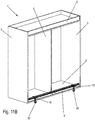
- FIGs 11A and 11B is on the top floor, in contrast to the Figures 10 Furniture 1 'rotated by 180 ° is shown.
- two assembly tools 10 are used, which position the guide rail 40 together with a bar 9 on an underside of the upper floor, in order to then fix the guide rail 40 together with the bar 9 on the upper floor.
- the assembly can therefore as in the Figures 8 or 9 take place, the guide rail 30 or 40 optionally on the underside or the top of the plate-shaped furniture part 5.
- the assembly tool 10 can thus be added when a piece of cupboard furniture is delivered so that the fitter or end user can easily align and fix the guide rail 30 or 40 in a simple manner.
Landscapes
- Furniture Connections (AREA)
Claims (9)
- Outil de montage (10) pour le montage d'un rail de guidage (30, 40) sur une partie de meuble en forme de plaque (5), comportant un corps moulé (11) avec au moins un logement (12, 13) pour la fixation d'un rail de guidage (30, 40) et une section de butée angulaire (14) qui peut être placée contre un bord d'extrémité et une surface de la partie de meuble en forme de plaque (5), dans lequel il est prévu un élément de ressort (20) qui est destiné à fixer par serrage le corps moulé (11) sur la partie de meuble en forme de plaque (5), caractérisé en ce que l'élément de ressort (20) est formé d'un seul tenant avec le corps moulé (11) et peut être monté sur le corps moulé (11) après avoir découpé un point de rupture prédéterminé (19).
- Outil de montage selon la revendication 1, caractérisé en ce que sur le corps moulé (11) sont prévus au moins deux logements espacés (12, 13) pour la fixation de rails de guidage (30, 40) avec des sections transversales de profil différentes.
- Outil de montage selon la revendication 1 ou 2, caractérisé en ce que le rail de guidage (30, 40) peut être fixé par serrage sur ou dans le réceptacle (12, 13).
- Outil d'assemblage selon l'une des revendications précédentes, caractérisé en ce que l'élément de ressort (20) peut être fixé dans différentes positions de raccordement (24, 25) sur les corps moulés (11).
- Outil d'assemblage selon l'une des revendications précédentes, caractérisé en ce qu'une ouverture de préhension (26) est formée sur le corps moulé (11).
- Outil de montage selon l'une des revendications précédentes, caractérisé en ce que l'élément de ressort (20) présente une partie de pied (21) qui peut être insérée ou poussée dans un logement (24, 25) sur le corps moulé (11).
- Outil d'assemblage selon l'une des revendications précédentes, caractérisé en ce que le corps moulé (11) est fabriqué en matière plastique, de préférence par moulage par injection ou par extrusion.
- Méthode de montage d'un rail de guidage (30, 40) sur une partie de meuble en forme de plaque (5), comprenant les étapes suivantes :- Fixation du rail de guidage (30, 40) sur ou dans un réceptacle (12, 13) d'une corps moulé (11) ;- le positionnement d'une section de butée angulaire (14) sur un bord d'extrémité et une surface de la partie de meuble en forme de plaque (5), et- Fixation du rail de guidage (30, 40) à la partie de meuble en forme de plaque, dans laquelle un élément de ressort (20) est prévu sur le corps moulé (11), lequel élément de ressort (20) est appliqué à la partie de meuble en forme de plaque sur le côté opposé au rail de guidage (30, 40),caractérisé en ce que ledit élément de ressort (20) est formé d'un seul tenant avec ledit corps de moule et est séparé dudit corps moulé (11) en coupant un point de rupture prédéterminé, puis réassemblé audit corps de moule (11) à une position de connexion prédéterminée.
- Procédé selon la revendication 8, caractérisé en ce que le rail de guidage (30, 40) est maintenu sur une face inférieure de la partie de meuble en forme de plaque (5) par au moins deux corps moulé (11).
Applications Claiming Priority (1)
| Application Number | Priority Date | Filing Date | Title |
|---|---|---|---|
| DE102017110329.5A DE102017110329A1 (de) | 2017-05-12 | 2017-05-12 | Montagewerkzeug und Verfahren zur Montage einer Führungsschiene an einem plattenförmigen Möbelteil |
Publications (2)
| Publication Number | Publication Date |
|---|---|
| EP3400832A1 EP3400832A1 (fr) | 2018-11-14 |
| EP3400832B1 true EP3400832B1 (fr) | 2020-04-15 |
Family
ID=62148228
Family Applications (1)
| Application Number | Title | Priority Date | Filing Date |
|---|---|---|---|
| EP18171585.5A Active EP3400832B1 (fr) | 2017-05-12 | 2018-05-09 | Outil d'assemblage et procédé d'assemblage d'un rail de guidage sur une pièce de mobilier moulé en plaque |
Country Status (2)
| Country | Link |
|---|---|
| EP (1) | EP3400832B1 (fr) |
| DE (1) | DE102017110329A1 (fr) |
Families Citing this family (1)
| Publication number | Priority date | Publication date | Assignee | Title |
|---|---|---|---|---|
| DE102023117386A1 (de) | 2023-06-30 | 2025-01-02 | Paul Hettich Gmbh & Co. Kg | Verfahren zur Montage eines Funktionsbeschlages und Bausatz |
Citations (1)
| Publication number | Priority date | Publication date | Assignee | Title |
|---|---|---|---|---|
| DE202017100195U1 (de) * | 2016-01-21 | 2017-02-22 | Inter Ikea Systems B.V. | Systeme und Vorrichtungen zur Verbindung von Regalen |
Family Cites Families (8)
| Publication number | Priority date | Publication date | Assignee | Title |
|---|---|---|---|---|
| AT380777B (de) * | 1983-11-11 | 1986-07-10 | Fulterer Gmbh | Anschlagwerkzeug zur winkelgerechten montage von korpusschienen von schubladenfuehrungen |
| AT380778B (de) * | 1984-11-19 | 1986-07-10 | Blum Gmbh Julius | Anschlaglehre |
| AT398516B (de) * | 1992-02-05 | 1994-12-27 | Fulterer Gmbh | Schubkastenauszug |
| AT404220B (de) * | 1994-07-13 | 1998-09-25 | Alfit Ag | Vorrichtung zur befestigung einer auszugsführung |
| US7281338B2 (en) * | 2003-09-30 | 2007-10-16 | Npz Inc. | Slide mounting tools, kits and systems containing same and methods related thereto |
| TW200944157A (en) * | 2008-04-18 | 2009-11-01 | King Slide Works Co Ltd | Positioning device for a drawer with a drawer slide |
| US7979998B2 (en) * | 2009-11-09 | 2011-07-19 | Neil Ziegmann | Slide mounting tool and method of use |
| KR101406781B1 (ko) * | 2012-10-24 | 2014-06-17 | 박윤식 | 서랍용 슬라이드 탈착장치 |
-
2017
- 2017-05-12 DE DE102017110329.5A patent/DE102017110329A1/de not_active Withdrawn
-
2018
- 2018-05-09 EP EP18171585.5A patent/EP3400832B1/fr active Active
Patent Citations (1)
| Publication number | Priority date | Publication date | Assignee | Title |
|---|---|---|---|---|
| DE202017100195U1 (de) * | 2016-01-21 | 2017-02-22 | Inter Ikea Systems B.V. | Systeme und Vorrichtungen zur Verbindung von Regalen |
Also Published As
| Publication number | Publication date |
|---|---|
| EP3400832A1 (fr) | 2018-11-14 |
| DE102017110329A1 (de) | 2018-11-15 |
Similar Documents
| Publication | Publication Date | Title |
|---|---|---|
| EP2814356B1 (fr) | Tiroir | |
| EP2750550B1 (fr) | Tiroir | |
| DE102007035648A1 (de) | Tafelförmiges Paneel mit separatem Rastelement | |
| DE20080141U1 (de) | Bauteile oder Anordnung mit derartigen Bauteilen und Klammer hierfür | |
| WO2013056282A1 (fr) | Dispositif d'assemblage de deux éléments de paroi de tiroir à disposer à angle droit | |
| DE102008019421A1 (de) | Beschlagaufbau und Verfahren zur höhenrichtigen Montage einer Dekorplatte an einer Tür eines Haushaltsgeräts | |
| DE102017102643B4 (de) | Schubkasten und Verfahren zur Montage einer Rückwand an einer Seitenzarge eines Schubkastens | |
| EP3579726B1 (fr) | Tiroir coulissant | |
| DE202007015605U1 (de) | Verbindungsbeschlag und Montageanordnung | |
| DE102016103169B4 (de) | Adapter zur Fixierung eines Bodens an einer Seitenzarge, Schubkasten und Verfahren zur Montage eines Bodens an einem Adapter | |
| EP3400832B1 (fr) | Outil d'assemblage et procédé d'assemblage d'un rail de guidage sur une pièce de mobilier moulé en plaque | |
| DE102017103595A1 (de) | Adapter und Verfahren zur Montage eines Schubkastens | |
| EP2479365A1 (fr) | Rail de guidage pour portes coulissantes ou repliables en accordéon | |
| DE102010060672B4 (de) | Fenster- oder Türrahmen | |
| DE102012104918A1 (de) | Steckverbindung | |
| EP2067906B1 (fr) | Système de connexion pour tiges de profil en forme de cannelure et agencement de connexion | |
| EP2199509A2 (fr) | Bloc d'armature pour un système d'armature de tige motrice | |
| DE202009002713U1 (de) | Gleitbeschlag | |
| DE102016103520B3 (de) | Türzargenanordnung sowie Distanzstück für eine Türzargenanordnung | |
| EP1780345A2 (fr) | Raccord pour profilés de forme d'un U et ensemble de connexion | |
| EP4181734B1 (fr) | Unité adaptateur pour relier une base de tiroir à un cadre latéral d'un tiroir, cadre latéral et tiroir | |
| DE102020123839A1 (de) | Verbindungselement für ein Möbelstück, Stecksystem mit einem solchen Verbindungselement und ein Verfahren zur Montage eines Möbelstücks | |
| WO2021032539A1 (fr) | Tiroir | |
| EP3824760B1 (fr) | Meuble | |
| DE102023113168A1 (de) | Verbinder für eine schraublose Verbindung einer Gittermatte an einen Zaunpfosten |
Legal Events
| Date | Code | Title | Description |
|---|---|---|---|
| PUAI | Public reference made under article 153(3) epc to a published international application that has entered the european phase |
Free format text: ORIGINAL CODE: 0009012 |
|
| STAA | Information on the status of an ep patent application or granted ep patent |
Free format text: STATUS: THE APPLICATION HAS BEEN PUBLISHED |
|
| AK | Designated contracting states |
Kind code of ref document: A1 Designated state(s): AL AT BE BG CH CY CZ DE DK EE ES FI FR GB GR HR HU IE IS IT LI LT LU LV MC MK MT NL NO PL PT RO RS SE SI SK SM TR |
|
| AX | Request for extension of the european patent |
Extension state: BA ME |
|
| STAA | Information on the status of an ep patent application or granted ep patent |
Free format text: STATUS: REQUEST FOR EXAMINATION WAS MADE |
|
| 17P | Request for examination filed |
Effective date: 20190212 |
|
| RBV | Designated contracting states (corrected) |
Designated state(s): AL AT BE BG CH CY CZ DE DK EE ES FI FR GB GR HR HU IE IS IT LI LT LU LV MC MK MT NL NO PL PT RO RS SE SI SK SM TR |
|
| RIC1 | Information provided on ipc code assigned before grant |
Ipc: A47B 88/423 20170101AFI20190409BHEP |
|
| STAA | Information on the status of an ep patent application or granted ep patent |
Free format text: STATUS: EXAMINATION IS IN PROGRESS |
|
| 17Q | First examination report despatched |
Effective date: 20190708 |
|
| GRAP | Despatch of communication of intention to grant a patent |
Free format text: ORIGINAL CODE: EPIDOSNIGR1 |
|
| STAA | Information on the status of an ep patent application or granted ep patent |
Free format text: STATUS: GRANT OF PATENT IS INTENDED |
|
| INTG | Intention to grant announced |
Effective date: 20200109 |
|
| GRAS | Grant fee paid |
Free format text: ORIGINAL CODE: EPIDOSNIGR3 |
|
| GRAA | (expected) grant |
Free format text: ORIGINAL CODE: 0009210 |
|
| STAA | Information on the status of an ep patent application or granted ep patent |
Free format text: STATUS: THE PATENT HAS BEEN GRANTED |
|
| AK | Designated contracting states |
Kind code of ref document: B1 Designated state(s): AL AT BE BG CH CY CZ DE DK EE ES FI FR GB GR HR HU IE IS IT LI LT LU LV MC MK MT NL NO PL PT RO RS SE SI SK SM TR |
|
| REG | Reference to a national code |
Ref country code: CH Ref legal event code: EP |
|
| REG | Reference to a national code |
Ref country code: DE Ref legal event code: R096 Ref document number: 502018001184 Country of ref document: DE |
|
| REG | Reference to a national code |
Ref country code: IE Ref legal event code: FG4D Free format text: LANGUAGE OF EP DOCUMENT: GERMAN |
|
| REG | Reference to a national code |
Ref country code: AT Ref legal event code: REF Ref document number: 1256283 Country of ref document: AT Kind code of ref document: T Effective date: 20200515 |
|
| REG | Reference to a national code |
Ref country code: NL Ref legal event code: MP Effective date: 20200415 |
|
| REG | Reference to a national code |
Ref country code: LT Ref legal event code: MG4D |
|
| PG25 | Lapsed in a contracting state [announced via postgrant information from national office to epo] |
Ref country code: GR Free format text: LAPSE BECAUSE OF FAILURE TO SUBMIT A TRANSLATION OF THE DESCRIPTION OR TO PAY THE FEE WITHIN THE PRESCRIBED TIME-LIMIT Effective date: 20200716 Ref country code: NO Free format text: LAPSE BECAUSE OF FAILURE TO SUBMIT A TRANSLATION OF THE DESCRIPTION OR TO PAY THE FEE WITHIN THE PRESCRIBED TIME-LIMIT Effective date: 20200715 Ref country code: IS Free format text: LAPSE BECAUSE OF FAILURE TO SUBMIT A TRANSLATION OF THE DESCRIPTION OR TO PAY THE FEE WITHIN THE PRESCRIBED TIME-LIMIT Effective date: 20200815 Ref country code: PT Free format text: LAPSE BECAUSE OF FAILURE TO SUBMIT A TRANSLATION OF THE DESCRIPTION OR TO PAY THE FEE WITHIN THE PRESCRIBED TIME-LIMIT Effective date: 20200817 Ref country code: NL Free format text: LAPSE BECAUSE OF FAILURE TO SUBMIT A TRANSLATION OF THE DESCRIPTION OR TO PAY THE FEE WITHIN THE PRESCRIBED TIME-LIMIT Effective date: 20200415 Ref country code: LT Free format text: LAPSE BECAUSE OF FAILURE TO SUBMIT A TRANSLATION OF THE DESCRIPTION OR TO PAY THE FEE WITHIN THE PRESCRIBED TIME-LIMIT Effective date: 20200415 Ref country code: SE Free format text: LAPSE BECAUSE OF FAILURE TO SUBMIT A TRANSLATION OF THE DESCRIPTION OR TO PAY THE FEE WITHIN THE PRESCRIBED TIME-LIMIT Effective date: 20200415 Ref country code: FI Free format text: LAPSE BECAUSE OF FAILURE TO SUBMIT A TRANSLATION OF THE DESCRIPTION OR TO PAY THE FEE WITHIN THE PRESCRIBED TIME-LIMIT Effective date: 20200415 |
|
| PG25 | Lapsed in a contracting state [announced via postgrant information from national office to epo] |
Ref country code: HR Free format text: LAPSE BECAUSE OF FAILURE TO SUBMIT A TRANSLATION OF THE DESCRIPTION OR TO PAY THE FEE WITHIN THE PRESCRIBED TIME-LIMIT Effective date: 20200415 Ref country code: LV Free format text: LAPSE BECAUSE OF FAILURE TO SUBMIT A TRANSLATION OF THE DESCRIPTION OR TO PAY THE FEE WITHIN THE PRESCRIBED TIME-LIMIT Effective date: 20200415 Ref country code: BG Free format text: LAPSE BECAUSE OF FAILURE TO SUBMIT A TRANSLATION OF THE DESCRIPTION OR TO PAY THE FEE WITHIN THE PRESCRIBED TIME-LIMIT Effective date: 20200715 Ref country code: RS Free format text: LAPSE BECAUSE OF FAILURE TO SUBMIT A TRANSLATION OF THE DESCRIPTION OR TO PAY THE FEE WITHIN THE PRESCRIBED TIME-LIMIT Effective date: 20200415 |
|
| PG25 | Lapsed in a contracting state [announced via postgrant information from national office to epo] |
Ref country code: AL Free format text: LAPSE BECAUSE OF FAILURE TO SUBMIT A TRANSLATION OF THE DESCRIPTION OR TO PAY THE FEE WITHIN THE PRESCRIBED TIME-LIMIT Effective date: 20200415 |
|
| REG | Reference to a national code |
Ref country code: DE Ref legal event code: R097 Ref document number: 502018001184 Country of ref document: DE |
|
| PG25 | Lapsed in a contracting state [announced via postgrant information from national office to epo] |
Ref country code: ES Free format text: LAPSE BECAUSE OF FAILURE TO SUBMIT A TRANSLATION OF THE DESCRIPTION OR TO PAY THE FEE WITHIN THE PRESCRIBED TIME-LIMIT Effective date: 20200415 Ref country code: MC Free format text: LAPSE BECAUSE OF FAILURE TO SUBMIT A TRANSLATION OF THE DESCRIPTION OR TO PAY THE FEE WITHIN THE PRESCRIBED TIME-LIMIT Effective date: 20200415 Ref country code: IT Free format text: LAPSE BECAUSE OF FAILURE TO SUBMIT A TRANSLATION OF THE DESCRIPTION OR TO PAY THE FEE WITHIN THE PRESCRIBED TIME-LIMIT Effective date: 20200415 Ref country code: CZ Free format text: LAPSE BECAUSE OF FAILURE TO SUBMIT A TRANSLATION OF THE DESCRIPTION OR TO PAY THE FEE WITHIN THE PRESCRIBED TIME-LIMIT Effective date: 20200415 Ref country code: RO Free format text: LAPSE BECAUSE OF FAILURE TO SUBMIT A TRANSLATION OF THE DESCRIPTION OR TO PAY THE FEE WITHIN THE PRESCRIBED TIME-LIMIT Effective date: 20200415 Ref country code: EE Free format text: LAPSE BECAUSE OF FAILURE TO SUBMIT A TRANSLATION OF THE DESCRIPTION OR TO PAY THE FEE WITHIN THE PRESCRIBED TIME-LIMIT Effective date: 20200415 Ref country code: SM Free format text: LAPSE BECAUSE OF FAILURE TO SUBMIT A TRANSLATION OF THE DESCRIPTION OR TO PAY THE FEE WITHIN THE PRESCRIBED TIME-LIMIT Effective date: 20200415 Ref country code: DK Free format text: LAPSE BECAUSE OF FAILURE TO SUBMIT A TRANSLATION OF THE DESCRIPTION OR TO PAY THE FEE WITHIN THE PRESCRIBED TIME-LIMIT Effective date: 20200415 |
|
| PLBE | No opposition filed within time limit |
Free format text: ORIGINAL CODE: 0009261 |
|
| STAA | Information on the status of an ep patent application or granted ep patent |
Free format text: STATUS: NO OPPOSITION FILED WITHIN TIME LIMIT |
|
| PG25 | Lapsed in a contracting state [announced via postgrant information from national office to epo] |
Ref country code: SK Free format text: LAPSE BECAUSE OF FAILURE TO SUBMIT A TRANSLATION OF THE DESCRIPTION OR TO PAY THE FEE WITHIN THE PRESCRIBED TIME-LIMIT Effective date: 20200415 Ref country code: PL Free format text: LAPSE BECAUSE OF FAILURE TO SUBMIT A TRANSLATION OF THE DESCRIPTION OR TO PAY THE FEE WITHIN THE PRESCRIBED TIME-LIMIT Effective date: 20200415 |
|
| REG | Reference to a national code |
Ref country code: BE Ref legal event code: MM Effective date: 20200531 |
|
| 26N | No opposition filed |
Effective date: 20210118 |
|
| PG25 | Lapsed in a contracting state [announced via postgrant information from national office to epo] |
Ref country code: LU Free format text: LAPSE BECAUSE OF NON-PAYMENT OF DUE FEES Effective date: 20200509 |
|
| PG25 | Lapsed in a contracting state [announced via postgrant information from national office to epo] |
Ref country code: FR Free format text: LAPSE BECAUSE OF NON-PAYMENT OF DUE FEES Effective date: 20200615 Ref country code: IE Free format text: LAPSE BECAUSE OF NON-PAYMENT OF DUE FEES Effective date: 20200509 |
|
| PG25 | Lapsed in a contracting state [announced via postgrant information from national office to epo] |
Ref country code: BE Free format text: LAPSE BECAUSE OF NON-PAYMENT OF DUE FEES Effective date: 20200531 Ref country code: SI Free format text: LAPSE BECAUSE OF FAILURE TO SUBMIT A TRANSLATION OF THE DESCRIPTION OR TO PAY THE FEE WITHIN THE PRESCRIBED TIME-LIMIT Effective date: 20200415 |
|
| REG | Reference to a national code |
Ref country code: CH Ref legal event code: PL |
|
| PG25 | Lapsed in a contracting state [announced via postgrant information from national office to epo] |
Ref country code: LI Free format text: LAPSE BECAUSE OF NON-PAYMENT OF DUE FEES Effective date: 20210531 Ref country code: CH Free format text: LAPSE BECAUSE OF NON-PAYMENT OF DUE FEES Effective date: 20210531 |
|
| PG25 | Lapsed in a contracting state [announced via postgrant information from national office to epo] |
Ref country code: TR Free format text: LAPSE BECAUSE OF FAILURE TO SUBMIT A TRANSLATION OF THE DESCRIPTION OR TO PAY THE FEE WITHIN THE PRESCRIBED TIME-LIMIT Effective date: 20200415 Ref country code: MT Free format text: LAPSE BECAUSE OF FAILURE TO SUBMIT A TRANSLATION OF THE DESCRIPTION OR TO PAY THE FEE WITHIN THE PRESCRIBED TIME-LIMIT Effective date: 20200415 Ref country code: CY Free format text: LAPSE BECAUSE OF FAILURE TO SUBMIT A TRANSLATION OF THE DESCRIPTION OR TO PAY THE FEE WITHIN THE PRESCRIBED TIME-LIMIT Effective date: 20200415 |
|
| PG25 | Lapsed in a contracting state [announced via postgrant information from national office to epo] |
Ref country code: MK Free format text: LAPSE BECAUSE OF FAILURE TO SUBMIT A TRANSLATION OF THE DESCRIPTION OR TO PAY THE FEE WITHIN THE PRESCRIBED TIME-LIMIT Effective date: 20200415 |
|
| GBPC | Gb: european patent ceased through non-payment of renewal fee |
Effective date: 20220509 |
|
| PG25 | Lapsed in a contracting state [announced via postgrant information from national office to epo] |
Ref country code: GB Free format text: LAPSE BECAUSE OF NON-PAYMENT OF DUE FEES Effective date: 20220509 |
|
| P01 | Opt-out of the competence of the unified patent court (upc) registered |
Effective date: 20230416 |
|
| REG | Reference to a national code |
Ref country code: AT Ref legal event code: MM01 Ref document number: 1256283 Country of ref document: AT Kind code of ref document: T Effective date: 20230509 |
|
| PG25 | Lapsed in a contracting state [announced via postgrant information from national office to epo] |
Ref country code: AT Free format text: LAPSE BECAUSE OF NON-PAYMENT OF DUE FEES Effective date: 20230509 |
|
| PG25 | Lapsed in a contracting state [announced via postgrant information from national office to epo] |
Ref country code: AT Free format text: LAPSE BECAUSE OF NON-PAYMENT OF DUE FEES Effective date: 20230509 |
|
| PGFP | Annual fee paid to national office [announced via postgrant information from national office to epo] |
Ref country code: DE Payment date: 20250519 Year of fee payment: 8 |
|
| PGFP | Annual fee paid to national office [announced via postgrant information from national office to epo] |
Ref country code: AT Payment date: 20260410 Year of fee payment: 5 |