EP2199509A2 - Bloc d'armature pour un système d'armature de tige motrice - Google Patents
Bloc d'armature pour un système d'armature de tige motrice Download PDFInfo
- Publication number
- EP2199509A2 EP2199509A2 EP09178447A EP09178447A EP2199509A2 EP 2199509 A2 EP2199509 A2 EP 2199509A2 EP 09178447 A EP09178447 A EP 09178447A EP 09178447 A EP09178447 A EP 09178447A EP 2199509 A2 EP2199509 A2 EP 2199509A2
- Authority
- EP
- European Patent Office
- Prior art keywords
- drive rod
- fitting assembly
- rod section
- guide
- rail
- Prior art date
- Legal status (The legal status is an assumption and is not a legal conclusion. Google has not performed a legal analysis and makes no representation as to the accuracy of the status listed.)
- Granted
Links
Images


Classifications
-
- E—FIXED CONSTRUCTIONS
- E05—LOCKS; KEYS; WINDOW OR DOOR FITTINGS; SAFES
- E05C—BOLTS OR FASTENING DEVICES FOR WINGS, SPECIALLY FOR DOORS OR WINDOWS
- E05C9/00—Arrangements of simultaneously actuated bolts or other securing devices at well-separated positions on the same wing
- E05C9/24—Means for transmitting movements between vertical and horizontal sliding bars, rods or cables for the fastening of wings, e.g. corner guides
Definitions
- the present invention relates to a fitting assembly for a window or door sash fitting system comprising a faceplate and at least one guide member for an espagnolette section fixed to the faceplate, the guide member passing through an associated guide recess in the espagnolette section and guiding the espagnolette section for movement along the faceplate ,
- the guide element has in its remote from the faceplate area a the drive rod portion on its side facing away from the faceplate side holding portion.
- a fitting assembly according to the preamble of claim 1 is known from DE 196 46 988 C2 known.
- a guide element designed as a plastic component is fixed at its two end regions located in the cuff rail longitudinal direction by latching on the faceplate rail. In this state, the guide element passes through a guide recess in a longitudinal direction of the face plate to leading drive rod section. At its end region remote from the faceplate, the guide element engages behind the drive rod section, which faces away from the faceplate, with the contact surfaces formed on it.
- the guide element with its region also serving as a guide to the face-plate is guided through the guide recess in an espagnolette section until the abutment surfaces rest on both sides of the guide recess on the side of the espagnolette section facing away from the face-plate ,
- the drive rod section can then be brought together with the guide element to the faceplate and the guide element are fixed to the faceplate.
- the leading one Espagnolette section then lies between the guide elements provided on the contact surfaces and the faceplate.
- the guide element has on both sides thereof integrally formed elastically on or rebound Klemmfixierabitese.
- the Klemmfixierabitese When inserting a fitting assembly thus constructed for an espagnolette fitting in a groove provided on a window or door wing, the Klemmfixierabitese put under bias against the two a groove laterally delimiting walls and thus ensure a clamping fixation of the fitting assembly in the inserted into the groove Status. Subsequently, then, the fitting assembly can be completely fixed, for example, by this interspersed and engaging in a window or door sash screws.
- a fitting assembly for an espagnolette fitting system for a window or door leaf comprising a faceplate and at least one of the faceplate fixed guide element for a drive rod section, wherein the guide element passes through an associated guide recess in the drive rod section and the drive rod section for movement along the face plate, wherein the guide element has at its remote from the face plate area a the drive rod section on its side facing away from the faceplate side holding portion ,
- the holding portion comprises a plurality of the guide recess passing through and the driving rod portion engages behind, biased into a holding position holder keys.
- the retaining action of the holding region provided on the guide element is achieved by the retaining elements pretensioned in a holding position.
- the guide member can be performed with the holding keys of its holding portion through an associated guide recess in a drive rod section, wherein the holder keys initially spring due to their bias and then when completely through the Guide recess are passed, rebound again and thus engage behind the drive rod section on its side facing away from the faceplate to be positioned side.
- the retaining elements with latching heads are resiliently springing through the guide recess to pass and engage the espagnolette with the locking heads at the exit of the locking heads from the guide recess, wherein the locking connection is particularly easy to achieve when the holder keys are formed with insertion bevels.
- At least one retaining key is provided in association with each longitudinal side of the guide recess.
- At least one Klemmfixierabites is provided on each side - side relative to the Stulpschienenlteilsraum.
- the Klemmfixierabitese extend in their over the drive rod portion laterally projecting portion in the direction of the faceplate and laterally outwardly curved.
- a mutual overlapping of the cuff rails of various fitting assemblies in an espagnolette fitting system can be achieved in that the faceplate in at least one Stulpschienenend Scheme comprises an offset by bending the espagnolette Stulpschienenendabêt, and that in association with at least one Stulpschienenend Scheme a Stulpschienenendabrough in Stulpschienenltellsraum at least partially overlapping guide element is provided.
- the Klemmfixierabitese may be arranged extending between the Stulpschienenendabêt and the drive rod portion so that they are protected in the region in which they extend laterally outwardly through the Stulpschienenabrough or the drive rod section against excessive bending.
- the faceplate is designed as Eckstulpschiene with two mutually angled Stulpschienenschenkeln, and that in association with at least one, preferably both, Stulpschienenschenkeln a driving rod portion leading guide element is provided.
- drive rod sections are coupled together by a displaceable in a guide channel flexible coupling element.
- the guide element can be fixed to the cuff rail before or after the connection thereof with a drive rod section leading to it.
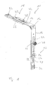
- FIG. 1 and 2 is designed as a corner deflection fitting assembly for a drive rod fitting system generally designated 10.
- This Eckumlenkung or fitting assembly 10 includes a face plate 12 with two at an angle of 90 ° to each other angled extending Stulpschienenschenkeln 14, 16. In their respective end regions 18, 20, the Stulpschienenschenkel 14, 16 with end portions 22, 24 formed in the region of Bent offset offset to the main areas of the cuff rail legs 14, 16.
- a guide element 26 which will be described in more detail below, is provided on the cuff rail limbs 14, 16 or attached to the face-plate rail 12.
- the guide elements 26 extend in the end regions 18, 20 in such a way that they substantially completely complete the end sections 22, 24 in a cuff rail longitudinal direction, which essentially corresponds to the longitudinal extent of the cuff rail legs 16, 16 in the case of a corner drive cover.
- a drive rod section 28, 30 is provided in association with each Stulpschienenschenkel 14, 16. These have, in their end regions, toothing-like coupling formations 32, 34 with which they can be coupled to drive rod sections of subsequently assembled fitting assemblies. In their other end regions, the drive rod sections 28, 30 are connected to a flexible coupling element 36. Rivet elements 38 and 40, which not only realize the fixed connection of the drive rod sections 28, 30 with the flexible coupling element 36, but also with their slot-like recesses 42, 44 in the cuff rail legs 14, 16 passing through or also beyond the locking areas 46 as can be attributed to the cuff leg 16 in the Fig. 1 and 2 is recognizable. Upon movement of the drive rod sections 28, 30 in each case in the longitudinal direction of the cuff rail legs 14, 16, the closing cams 46 also move in this direction.
- the flexible coupling element 36 which may be formed, for example, from spring band material or the like, is guided in a guide channel 48 formed with a C-shaped cross section, which can be fixed along the cuff rail legs 14, 16 to the latter, for example by rivet elements.
- a guide channel 48 formed with a C-shaped cross section, which can be fixed along the cuff rail legs 14, 16 to the latter, for example by rivet elements.
- the guide channel 48 for slot-through of the rivet elements 38, 40 serving slot-like recesses.
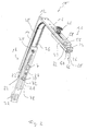
- the Fig. 3 shows an enlarged view of a guide member 26, as it is provided in association with both end portions 18, 20 of the faceplate 12 or can be.
- the guide member 26 has a generally denoted by 50 guide element body, which in adaptation to the staggered by bending end portions 22 and 24 a recess 52, in which a respective end portion 22 and 24 comes to rest.
- a fastening projection 54 can be received in an associated recess 56 of a respective end region 18 or 20 in order to fix the guide element 26 to the face-plate rail 12 by clamping action, possibly also by caulking or riveting thereof, so that it is basically parallel to its longitudinal direction is aligned.
- the guide member 26, as well as the faceplate 12 associated therewith have through holes 58, 60 and 62, 64, respectively, through which fastening screws may be passed to secure the fitting assembly 10 to a wing.
- the guide member 26 has a generally designated 68 holding area. This is formed with a plurality of retaining keys 70, 72 on the two longitudinal sides of the guide element, wherein each such retaining key has a latching head 74 with an insertion bevel 76.
- the holder keys 70, 72 are resilient, for which purpose, for example, the guide element 26 can be constructed of plastic material or correspondingly flexible metal material.
- the drive rod sections 28, 30 (in Fig. 4 the drive rod portion 30 can be seen) on a guide recess 78.
- the guide member 26 is received, and when fixed to the faceplate 12 guide member 26, such a drive rod portion 30 can then move under the guiding action of the guide member 26 in a defined direction along the longitudinal direction of the face-plate 12.
- the guide element 26 lies with its holding region 68, ie the latching heads 74, on a side 80 of the drive rod section 30 facing away from the face-plate rail 12 and engages behind it.
- the drive rod section is between the locking heads 74 and the guide element body 50 provided in the region of the recess 52 Klemmfixierabroughen 82, 84 and guided in its longitudinal direction.
- the two laterally over the drive rod portion 30 protruding Klemmfixierabroughe 82, 84 are in the assembled state, like the Fig. 2 this shows, in principle between a respective drive rod section 28 and 30 and the end portion 22 and 24 and engage laterally beyond these two components.
- protruding end portions extend the Klemmfixierabroughe 84 laterally outward and in the direction of the face-plate 12 to.
- the Klemmfixierabitese 82, 84 When inserting a fitting assembly 10 thus constructed, the Klemmfixierabitese 82, 84 come with their on the espagnolette sections 28, 30 protruding sections to rest against the one fitting assembly 10 receiving groove bounding side walls and braced against them. It is thus achieved a Vorarret mich by clamping action, so that it is ensured that before fitting the mounting screws, the fitting assembly 10 is held in a defined positioning on the window or door leaf. Since the clamp lock portions 82, 84 are held in a groove receiving them between the end portions 22 and 24 and the drive rod portions 28 and 30, respectively, upon insertion of such a fitting assembly 10, excessive flexing thereof can be precluded.
- FIGS. 5 and 6 illustrate the process of assembling a guide member 26 with a drive rod portion, here the drive rod portion 30.
- the guide member 26 is moved with its in the assembled state of the faceplate 12 remote area 66 to the drive rod portion 30 or vice versa, until the retaining keys 70, 72nd with their Abweisschrägen 74 on which the guide recess 78 in the drive rod section 30 surrounding area come to rest.
- the retaining keys 70, 72nd with their Abweisschrägen 74 on which the guide recess 78 in the drive rod section 30 surrounding area come to rest.
- the retaining clips 72, 74 continue to the deflection of the retaining clips 72, 74, so that these pass through the guide recess 78.
- the retaining clips 70, 72 again spring out laterally and with their latching heads 74 engage behind the drive rod section 30 on its side facing away from the face-plate rail 12. In this state, the drive rod section 30 is then guided between the latching heads 74 and the clamping lock sections 82, 84. or held.
- This embodiment of the guide elements 26 makes it possible with the associated drive rod sections 28 or 30 to the in Fig. 6 recognizable preassembled subassembly summarize, in which due to the mounting of the drive rod sections 28 and 30 between the locking heads 74 on the one hand and the Klemmarretierabêten 82, 84 on the other hand, a detachment of the holding elements 26 of the drive rod sections 28, 30 is not possible.
- This subassembly can then be brought to the faceplate and assembled with this, wherein the drive rod sections 28, 30 can be connected, for example, with the flexible coupling element 36.
- the procedure could also be such that first the guide elements 26 are fixed to the face-plate rail 12 and then the drive rod sections 28, 30 are guided and held in the manner previously described on the respective associated guide elements 26.
Landscapes
- Engineering & Computer Science (AREA)
- Mechanical Engineering (AREA)
- Power-Operated Mechanisms For Wings (AREA)
- Window Of Vehicle (AREA)
Priority Applications (1)
| Application Number | Priority Date | Filing Date | Title |
|---|---|---|---|
| PL09178447T PL2199509T3 (pl) | 2008-12-15 | 2009-12-09 | Podzespół okucia dla systemu okucia z prętem nastawczym |
Applications Claiming Priority (1)
| Application Number | Priority Date | Filing Date | Title |
|---|---|---|---|
| DE102008062303A DE102008062303A1 (de) | 2008-12-15 | 2008-12-15 | Beschlagbaugruppe für ein Treibstangenbeschlagsystem |
Publications (3)
| Publication Number | Publication Date |
|---|---|
| EP2199509A2 true EP2199509A2 (fr) | 2010-06-23 |
| EP2199509A3 EP2199509A3 (fr) | 2011-09-14 |
| EP2199509B1 EP2199509B1 (fr) | 2012-11-21 |
Family
ID=41819248
Family Applications (1)
| Application Number | Title | Priority Date | Filing Date |
|---|---|---|---|
| EP09178447A Not-in-force EP2199509B1 (fr) | 2008-12-15 | 2009-12-09 | Bloc d'armature pour un système d'armature de tige motrice |
Country Status (3)
| Country | Link |
|---|---|
| EP (1) | EP2199509B1 (fr) |
| DE (1) | DE102008062303A1 (fr) |
| PL (1) | PL2199509T3 (fr) |
Cited By (3)
| Publication number | Priority date | Publication date | Assignee | Title |
|---|---|---|---|---|
| DE102010042629A1 (de) | 2010-10-19 | 2012-04-19 | Aug. Winkhaus Gmbh & Co. Kg | Halteelement eines Beschlagteils eines Treibstangenbeschlages |
| DE102010042628A1 (de) | 2010-10-19 | 2012-04-19 | Aug. Winkhaus Gmbh & Co. Kg | Halteelement eines Beschlagteils eines Treibstangenbeschlages |
| CN110242159A (zh) * | 2019-07-25 | 2019-09-17 | 深圳好博窗控技术有限公司 | 快装连接头、传动杆、连接组件及门窗结构 |
Family Cites Families (5)
| Publication number | Priority date | Publication date | Assignee | Title |
|---|---|---|---|---|
| DE4138741C2 (de) * | 1991-11-26 | 1995-02-02 | Bilstein August Gmbh Co Kg | Befestigung für eine Beschlags-Eckumlenkung |
| DE19646988C5 (de) | 1996-11-14 | 2014-07-03 | Roto Frank Ag | Beschlag für ein Fenster |
| FR2849091B1 (fr) * | 2002-12-19 | 2005-09-23 | Ferco Int Usine Ferrures | Guide de sortie de tringle pour cremone, cremone-serrure ou similaire |
| EP1559856B1 (fr) * | 2004-01-27 | 2013-08-28 | Roto Frank Ag | Fenêtre, porte ou similaires avec ferrure avec une têtière |
| DE102007053340A1 (de) | 2007-11-08 | 2009-05-14 | Aug. Winkhaus Gmbh & Co. Kg | Eckumlenkung für ein Treibstangenbeschlagsystem für einen Fenster- oder Türflügel |
-
2008
- 2008-12-15 DE DE102008062303A patent/DE102008062303A1/de not_active Withdrawn
-
2009
- 2009-12-09 EP EP09178447A patent/EP2199509B1/fr not_active Not-in-force
- 2009-12-09 PL PL09178447T patent/PL2199509T3/pl unknown
Cited By (8)
| Publication number | Priority date | Publication date | Assignee | Title |
|---|---|---|---|---|
| DE102010042629A1 (de) | 2010-10-19 | 2012-04-19 | Aug. Winkhaus Gmbh & Co. Kg | Halteelement eines Beschlagteils eines Treibstangenbeschlages |
| DE102010042628A1 (de) | 2010-10-19 | 2012-04-19 | Aug. Winkhaus Gmbh & Co. Kg | Halteelement eines Beschlagteils eines Treibstangenbeschlages |
| EP2444573A2 (fr) | 2010-10-19 | 2012-04-25 | Aug. Winkhaus GmbH & Co. KG | Elément de retenue d'une garniture de ferrure à tringle |
| EP2444574A2 (fr) | 2010-10-19 | 2012-04-25 | Aug. Winkhaus GmbH & Co. KG | Elément de retenue d'une garniture de ferrure à tringle |
| EP2444573A3 (fr) * | 2010-10-19 | 2016-12-28 | Aug. Winkhaus GmbH & Co. KG | Elément de retenue d'une garniture de ferrure à tringle |
| EP2444574A3 (fr) * | 2010-10-19 | 2016-12-28 | Aug. Winkhaus GmbH & Co. KG | Elément de retenue d'une garniture de ferrure à tringle |
| CN110242159A (zh) * | 2019-07-25 | 2019-09-17 | 深圳好博窗控技术有限公司 | 快装连接头、传动杆、连接组件及门窗结构 |
| CN110242159B (zh) * | 2019-07-25 | 2024-05-28 | 深圳好博窗控技术股份有限公司 | 快装连接头、传动杆、连接组件及门窗结构 |
Also Published As
| Publication number | Publication date |
|---|---|
| DE102008062303A1 (de) | 2010-06-17 |
| EP2199509A3 (fr) | 2011-09-14 |
| PL2199509T3 (pl) | 2013-04-30 |
| EP2199509B1 (fr) | 2012-11-21 |
Similar Documents
| Publication | Publication Date | Title |
|---|---|---|
| EP2443003A1 (fr) | Ensemble de liaison | |
| EP1441094A1 (fr) | Ferrure pour une fênetre | |
| WO2011079972A1 (fr) | Armature pour portes ou fenêtres | |
| EP2860333A1 (fr) | Agencement de fermeture pour la fermeture de deux battants coulissants | |
| EP2199509B1 (fr) | Bloc d'armature pour un système d'armature de tige motrice | |
| EP2058463B1 (fr) | Renvoi d'angle pour un système d'armature de tige motrice pour un vantail de fenêtre ou de porte | |
| DE102007016667B4 (de) | Befestigungsanordnung | |
| EP2161401B1 (fr) | Agencement de liaison d'un moyen de traction et d'un élément d'entraîneur | |
| EP2295684B1 (fr) | Butée pour une fenêtre, une porte ou analogue, ainsi que fenêtre, porte ou analogue dotée d'une telle butée | |
| EP3173556B1 (fr) | Élément de montage destiné à fixer des pentures de porte | |
| DE602005003380T2 (de) | Verfahren zur Montage eines Verstärkungsteils auf die Frontplatte eines Kühl- oder Gefrierschrankes | |
| EP2754803A2 (fr) | Crémone de fenêtre ou de porte | |
| DE19834038C2 (de) | Treibstangenbeschlag mit Eckumlenkung | |
| EP3400832B1 (fr) | Outil d'assemblage et procédé d'assemblage d'un rail de guidage sur une pièce de mobilier moulé en plaque | |
| DE102014009000B3 (de) | Zweiteiliges Befestigungselement für einen mit einem Ankerkopf versehenen Anker | |
| EP2532816B1 (fr) | Dispositif d'entraînement pour une armature de bielle | |
| EP2620579A2 (fr) | Elément de liaison destiné à la liaison de pièces profilées | |
| EP1862622B1 (fr) | Pièce d'assemblage d'angle pour un ensemble de manoeuvre-têtière, pour fenêtres, portes ou similaires | |
| DE102004043581A1 (de) | Bauteilesatz aus wenigstens einer Sprosse und wenigstens zwei Sprossenendstücken zum Einbauen in eine Isolierglasscheibe | |
| EP1260662B1 (fr) | Dispositif d'accouplement pour tringles d'entraínement de ferrures à tringles | |
| EP3889446A1 (fr) | Procédé de fabrication d'un dispositif de fixation | |
| EP1002919B1 (fr) | Tringlerie de commande pour fenêtres, portes ou similaires | |
| EP1245768A2 (fr) | Têtière d'une crémone pour fenêtres, portes ou similaires et crémone avec une telle têtière | |
| EP2470729B1 (fr) | Pièce de montage et procédé de fabrication d'une pièce de montage | |
| EP2444573B1 (fr) | Elément de retenue d'une garniture de ferrure à tringle |
Legal Events
| Date | Code | Title | Description |
|---|---|---|---|
| PUAI | Public reference made under article 153(3) epc to a published international application that has entered the european phase |
Free format text: ORIGINAL CODE: 0009012 |
|
| AK | Designated contracting states |
Kind code of ref document: A2 Designated state(s): AT BE BG CH CY CZ DE DK EE ES FI FR GB GR HR HU IE IS IT LI LT LU LV MC MK MT NL NO PL PT RO SE SI SK SM TR |
|
| AX | Request for extension of the european patent |
Extension state: AL BA RS |
|
| PUAL | Search report despatched |
Free format text: ORIGINAL CODE: 0009013 |
|
| AK | Designated contracting states |
Kind code of ref document: A3 Designated state(s): AT BE BG CH CY CZ DE DK EE ES FI FR GB GR HR HU IE IS IT LI LT LU LV MC MK MT NL NO PL PT RO SE SI SK SM TR |
|
| AX | Request for extension of the european patent |
Extension state: AL BA RS |
|
| RIC1 | Information provided on ipc code assigned before grant |
Ipc: E05C 9/00 20060101AFI20110805BHEP |
|
| 17P | Request for examination filed |
Effective date: 20111206 |
|
| REG | Reference to a national code |
Ref country code: DE Ref legal event code: R079 Ref document number: 502009005437 Country of ref document: DE Free format text: PREVIOUS MAIN CLASS: E05C0009000000 Ipc: E05F0007080000 |
|
| GRAP | Despatch of communication of intention to grant a patent |
Free format text: ORIGINAL CODE: EPIDOSNIGR1 |
|
| RIC1 | Information provided on ipc code assigned before grant |
Ipc: E05C 9/00 20060101ALI20120626BHEP Ipc: E05F 7/08 20060101AFI20120626BHEP |
|
| GRAS | Grant fee paid |
Free format text: ORIGINAL CODE: EPIDOSNIGR3 |
|
| GRAA | (expected) grant |
Free format text: ORIGINAL CODE: 0009210 |
|
| AK | Designated contracting states |
Kind code of ref document: B1 Designated state(s): AT BE BG CH CY CZ DE DK EE ES FI FR GB GR HR HU IE IS IT LI LT LU LV MC MK MT NL NO PL PT RO SE SI SK SM TR |
|
| REG | Reference to a national code |
Ref country code: GB Ref legal event code: FG4D Free format text: NOT ENGLISH |
|
| REG | Reference to a national code |
Ref country code: CH Ref legal event code: EP |
|
| REG | Reference to a national code |
Ref country code: AT Ref legal event code: REF Ref document number: 585181 Country of ref document: AT Kind code of ref document: T Effective date: 20121215 |
|
| REG | Reference to a national code |
Ref country code: IE Ref legal event code: FG4D Free format text: LANGUAGE OF EP DOCUMENT: GERMAN |
|
| REG | Reference to a national code |
Ref country code: DE Ref legal event code: R096 Ref document number: 502009005437 Country of ref document: DE Effective date: 20130117 |
|
| REG | Reference to a national code |
Ref country code: NL Ref legal event code: VDEP Effective date: 20121121 |
|
| REG | Reference to a national code |
Ref country code: LT Ref legal event code: MG4D |
|
| PG25 | Lapsed in a contracting state [announced via postgrant information from national office to epo] |
Ref country code: LT Free format text: LAPSE BECAUSE OF FAILURE TO SUBMIT A TRANSLATION OF THE DESCRIPTION OR TO PAY THE FEE WITHIN THE PRESCRIBED TIME-LIMIT Effective date: 20121121 Ref country code: SE Free format text: LAPSE BECAUSE OF FAILURE TO SUBMIT A TRANSLATION OF THE DESCRIPTION OR TO PAY THE FEE WITHIN THE PRESCRIBED TIME-LIMIT Effective date: 20121121 Ref country code: FI Free format text: LAPSE BECAUSE OF FAILURE TO SUBMIT A TRANSLATION OF THE DESCRIPTION OR TO PAY THE FEE WITHIN THE PRESCRIBED TIME-LIMIT Effective date: 20121121 Ref country code: ES Free format text: LAPSE BECAUSE OF FAILURE TO SUBMIT A TRANSLATION OF THE DESCRIPTION OR TO PAY THE FEE WITHIN THE PRESCRIBED TIME-LIMIT Effective date: 20130304 Ref country code: NO Free format text: LAPSE BECAUSE OF FAILURE TO SUBMIT A TRANSLATION OF THE DESCRIPTION OR TO PAY THE FEE WITHIN THE PRESCRIBED TIME-LIMIT Effective date: 20130221 |
|
| REG | Reference to a national code |
Ref country code: PL Ref legal event code: T3 |
|
| PG25 | Lapsed in a contracting state [announced via postgrant information from national office to epo] |
Ref country code: LV Free format text: LAPSE BECAUSE OF FAILURE TO SUBMIT A TRANSLATION OF THE DESCRIPTION OR TO PAY THE FEE WITHIN THE PRESCRIBED TIME-LIMIT Effective date: 20121121 Ref country code: SI Free format text: LAPSE BECAUSE OF FAILURE TO SUBMIT A TRANSLATION OF THE DESCRIPTION OR TO PAY THE FEE WITHIN THE PRESCRIBED TIME-LIMIT Effective date: 20121121 Ref country code: GR Free format text: LAPSE BECAUSE OF FAILURE TO SUBMIT A TRANSLATION OF THE DESCRIPTION OR TO PAY THE FEE WITHIN THE PRESCRIBED TIME-LIMIT Effective date: 20130222 Ref country code: PT Free format text: LAPSE BECAUSE OF FAILURE TO SUBMIT A TRANSLATION OF THE DESCRIPTION OR TO PAY THE FEE WITHIN THE PRESCRIBED TIME-LIMIT Effective date: 20130321 |
|
| BERE | Be: lapsed |
Owner name: AUG. WINKHAUS G.M.B.H. & CO. KG Effective date: 20121231 |
|
| PG25 | Lapsed in a contracting state [announced via postgrant information from national office to epo] |
Ref country code: CZ Free format text: LAPSE BECAUSE OF FAILURE TO SUBMIT A TRANSLATION OF THE DESCRIPTION OR TO PAY THE FEE WITHIN THE PRESCRIBED TIME-LIMIT Effective date: 20121121 Ref country code: BG Free format text: LAPSE BECAUSE OF FAILURE TO SUBMIT A TRANSLATION OF THE DESCRIPTION OR TO PAY THE FEE WITHIN THE PRESCRIBED TIME-LIMIT Effective date: 20130221 Ref country code: MC Free format text: LAPSE BECAUSE OF NON-PAYMENT OF DUE FEES Effective date: 20121231 Ref country code: SK Free format text: LAPSE BECAUSE OF FAILURE TO SUBMIT A TRANSLATION OF THE DESCRIPTION OR TO PAY THE FEE WITHIN THE PRESCRIBED TIME-LIMIT Effective date: 20121121 Ref country code: DK Free format text: LAPSE BECAUSE OF FAILURE TO SUBMIT A TRANSLATION OF THE DESCRIPTION OR TO PAY THE FEE WITHIN THE PRESCRIBED TIME-LIMIT Effective date: 20121121 Ref country code: EE Free format text: LAPSE BECAUSE OF FAILURE TO SUBMIT A TRANSLATION OF THE DESCRIPTION OR TO PAY THE FEE WITHIN THE PRESCRIBED TIME-LIMIT Effective date: 20121121 |
|
| PG25 | Lapsed in a contracting state [announced via postgrant information from national office to epo] |
Ref country code: RO Free format text: LAPSE BECAUSE OF FAILURE TO SUBMIT A TRANSLATION OF THE DESCRIPTION OR TO PAY THE FEE WITHIN THE PRESCRIBED TIME-LIMIT Effective date: 20121121 Ref country code: NL Free format text: LAPSE BECAUSE OF FAILURE TO SUBMIT A TRANSLATION OF THE DESCRIPTION OR TO PAY THE FEE WITHIN THE PRESCRIBED TIME-LIMIT Effective date: 20121121 |
|
| REG | Reference to a national code |
Ref country code: IE Ref legal event code: MM4A |
|
| PLBE | No opposition filed within time limit |
Free format text: ORIGINAL CODE: 0009261 |
|
| STAA | Information on the status of an ep patent application or granted ep patent |
Free format text: STATUS: NO OPPOSITION FILED WITHIN TIME LIMIT |
|
| PG25 | Lapsed in a contracting state [announced via postgrant information from national office to epo] |
Ref country code: BE Free format text: LAPSE BECAUSE OF NON-PAYMENT OF DUE FEES Effective date: 20121231 |
|
| 26N | No opposition filed |
Effective date: 20130822 |
|
| PG25 | Lapsed in a contracting state [announced via postgrant information from national office to epo] |
Ref country code: IE Free format text: LAPSE BECAUSE OF NON-PAYMENT OF DUE FEES Effective date: 20121209 |
|
| PG25 | Lapsed in a contracting state [announced via postgrant information from national office to epo] |
Ref country code: MT Free format text: LAPSE BECAUSE OF FAILURE TO SUBMIT A TRANSLATION OF THE DESCRIPTION OR TO PAY THE FEE WITHIN THE PRESCRIBED TIME-LIMIT Effective date: 20121121 Ref country code: HR Free format text: LAPSE BECAUSE OF FAILURE TO SUBMIT A TRANSLATION OF THE DESCRIPTION OR TO PAY THE FEE WITHIN THE PRESCRIBED TIME-LIMIT Effective date: 20121121 |
|
| REG | Reference to a national code |
Ref country code: DE Ref legal event code: R097 Ref document number: 502009005437 Country of ref document: DE Effective date: 20130822 |
|
| PG25 | Lapsed in a contracting state [announced via postgrant information from national office to epo] |
Ref country code: CY Free format text: LAPSE BECAUSE OF FAILURE TO SUBMIT A TRANSLATION OF THE DESCRIPTION OR TO PAY THE FEE WITHIN THE PRESCRIBED TIME-LIMIT Effective date: 20121121 Ref country code: LU Free format text: LAPSE BECAUSE OF NON-PAYMENT OF DUE FEES Effective date: 20121209 Ref country code: SM Free format text: LAPSE BECAUSE OF FAILURE TO SUBMIT A TRANSLATION OF THE DESCRIPTION OR TO PAY THE FEE WITHIN THE PRESCRIBED TIME-LIMIT Effective date: 20121121 |
|
| PG25 | Lapsed in a contracting state [announced via postgrant information from national office to epo] |
Ref country code: HU Free format text: LAPSE BECAUSE OF FAILURE TO SUBMIT A TRANSLATION OF THE DESCRIPTION OR TO PAY THE FEE WITHIN THE PRESCRIBED TIME-LIMIT Effective date: 20091209 |
|
| REG | Reference to a national code |
Ref country code: CH Ref legal event code: PL |
|
| GBPC | Gb: european patent ceased through non-payment of renewal fee |
Effective date: 20131209 |
|
| PG25 | Lapsed in a contracting state [announced via postgrant information from national office to epo] |
Ref country code: CH Free format text: LAPSE BECAUSE OF NON-PAYMENT OF DUE FEES Effective date: 20131231 Ref country code: LI Free format text: LAPSE BECAUSE OF NON-PAYMENT OF DUE FEES Effective date: 20131231 |
|
| PG25 | Lapsed in a contracting state [announced via postgrant information from national office to epo] |
Ref country code: GB Free format text: LAPSE BECAUSE OF NON-PAYMENT OF DUE FEES Effective date: 20131209 |
|
| PGFP | Annual fee paid to national office [announced via postgrant information from national office to epo] |
Ref country code: TR Payment date: 20141112 Year of fee payment: 6 |
|
| PGFP | Annual fee paid to national office [announced via postgrant information from national office to epo] |
Ref country code: IT Payment date: 20141218 Year of fee payment: 6 |
|
| PG25 | Lapsed in a contracting state [announced via postgrant information from national office to epo] |
Ref country code: MK Free format text: LAPSE BECAUSE OF FAILURE TO SUBMIT A TRANSLATION OF THE DESCRIPTION OR TO PAY THE FEE WITHIN THE PRESCRIBED TIME-LIMIT Effective date: 20121121 |
|
| REG | Reference to a national code |
Ref country code: FR Ref legal event code: PLFP Year of fee payment: 7 |
|
| PG25 | Lapsed in a contracting state [announced via postgrant information from national office to epo] |
Ref country code: IS Free format text: LAPSE BECAUSE OF FAILURE TO SUBMIT A TRANSLATION OF THE DESCRIPTION OR TO PAY THE FEE WITHIN THE PRESCRIBED TIME-LIMIT Effective date: 20121121 |
|
| REG | Reference to a national code |
Ref country code: FR Ref legal event code: PLFP Year of fee payment: 8 |
|
| PG25 | Lapsed in a contracting state [announced via postgrant information from national office to epo] |
Ref country code: IT Free format text: LAPSE BECAUSE OF NON-PAYMENT OF DUE FEES Effective date: 20151209 |
|
| REG | Reference to a national code |
Ref country code: FR Ref legal event code: PLFP Year of fee payment: 9 |
|
| PGFP | Annual fee paid to national office [announced via postgrant information from national office to epo] |
Ref country code: FR Payment date: 20171226 Year of fee payment: 9 |
|
| PGFP | Annual fee paid to national office [announced via postgrant information from national office to epo] |
Ref country code: PL Payment date: 20171123 Year of fee payment: 9 |
|
| PG25 | Lapsed in a contracting state [announced via postgrant information from national office to epo] |
Ref country code: FR Free format text: LAPSE BECAUSE OF NON-PAYMENT OF DUE FEES Effective date: 20181231 |
|
| PG25 | Lapsed in a contracting state [announced via postgrant information from national office to epo] |
Ref country code: PL Free format text: LAPSE BECAUSE OF NON-PAYMENT OF DUE FEES Effective date: 20181209 |
|
| PGFP | Annual fee paid to national office [announced via postgrant information from national office to epo] |
Ref country code: AT Payment date: 20201218 Year of fee payment: 12 |
|
| REG | Reference to a national code |
Ref country code: AT Ref legal event code: MM01 Ref document number: 585181 Country of ref document: AT Kind code of ref document: T Effective date: 20211209 |
|
| PG25 | Lapsed in a contracting state [announced via postgrant information from national office to epo] |
Ref country code: AT Free format text: LAPSE BECAUSE OF NON-PAYMENT OF DUE FEES Effective date: 20211209 |
|
| PGFP | Annual fee paid to national office [announced via postgrant information from national office to epo] |
Ref country code: DE Payment date: 20221221 Year of fee payment: 14 |
|
| P01 | Opt-out of the competence of the unified patent court (upc) registered |
Effective date: 20230515 |
|
| REG | Reference to a national code |
Ref country code: DE Ref legal event code: R119 Ref document number: 502009005437 Country of ref document: DE |
|
| PG25 | Lapsed in a contracting state [announced via postgrant information from national office to epo] |
Ref country code: TR Free format text: LAPSE BECAUSE OF NON-PAYMENT OF DUE FEES Effective date: 20151209 |
|
| PG25 | Lapsed in a contracting state [announced via postgrant information from national office to epo] |
Ref country code: DE Free format text: LAPSE BECAUSE OF NON-PAYMENT OF DUE FEES Effective date: 20240702 |
|
| PG25 | Lapsed in a contracting state [announced via postgrant information from national office to epo] |
Ref country code: DE Free format text: LAPSE BECAUSE OF NON-PAYMENT OF DUE FEES Effective date: 20240702 |