EP3400921A1 - Dispositif de blocage d'un dispositif de transport de patients ainsi que dispositif de ceinture pour un dispositif de retenue pour patient et système de transport de patients - Google Patents
Dispositif de blocage d'un dispositif de transport de patients ainsi que dispositif de ceinture pour un dispositif de retenue pour patient et système de transport de patients Download PDFInfo
- Publication number
- EP3400921A1 EP3400921A1 EP18170985.8A EP18170985A EP3400921A1 EP 3400921 A1 EP3400921 A1 EP 3400921A1 EP 18170985 A EP18170985 A EP 18170985A EP 3400921 A1 EP3400921 A1 EP 3400921A1
- Authority
- EP
- European Patent Office
- Prior art keywords
- patient
- belt
- patient transport
- locking device
- base body
- Prior art date
- Legal status (The legal status is an assumption and is not a legal conclusion. Google has not performed a legal analysis and makes no representation as to the accuracy of the status listed.)
- Granted
Links
Images



Classifications
-
- A—HUMAN NECESSITIES
- A61—MEDICAL OR VETERINARY SCIENCE; HYGIENE
- A61G—TRANSPORT, PERSONAL CONVEYANCES, OR ACCOMMODATION SPECIALLY ADAPTED FOR PATIENTS OR DISABLED PERSONS; OPERATING TABLES OR CHAIRS; CHAIRS FOR DENTISTRY; FUNERAL DEVICES
- A61G1/00—Stretchers
- A61G1/04—Parts, details or accessories, e.g. head-, foot-, or like rests specially adapted for stretchers
- A61G1/044—Straps, bands or belts
-
- A—HUMAN NECESSITIES
- A61—MEDICAL OR VETERINARY SCIENCE; HYGIENE
- A61G—TRANSPORT, PERSONAL CONVEYANCES, OR ACCOMMODATION SPECIALLY ADAPTED FOR PATIENTS OR DISABLED PERSONS; OPERATING TABLES OR CHAIRS; CHAIRS FOR DENTISTRY; FUNERAL DEVICES
- A61G1/00—Stretchers
- A61G1/02—Stretchers with wheels
- A61G1/0206—Stretchers with wheels characterised by the number of supporting wheels if stretcher is extended
- A61G1/0212—2 pairs having wheels within a pair on the same position in longitudinal direction, e.g. on the same axis
-
- A—HUMAN NECESSITIES
- A61—MEDICAL OR VETERINARY SCIENCE; HYGIENE
- A61G—TRANSPORT, PERSONAL CONVEYANCES, OR ACCOMMODATION SPECIALLY ADAPTED FOR PATIENTS OR DISABLED PERSONS; OPERATING TABLES OR CHAIRS; CHAIRS FOR DENTISTRY; FUNERAL DEVICES
- A61G1/00—Stretchers
- A61G1/04—Parts, details or accessories, e.g. head-, foot-, or like rests specially adapted for stretchers
- A61G1/052—Struts, spars or legs
- A61G1/056—Swivelling legs
- A61G1/0562—Swivelling legs independently foldable, i.e. at least part of the leg folding movement is not simultaneous
Definitions
- the invention relates to a locking device of a patient transport device according to the preamble of claim 1, a belt device of a patient restraint device according to claim 8 and a patient transport device having the features according to claim 13.
- the aforementioned patient transport devices have a load-bearing basic structure and a patient restraint device.
- the load-bearing basic structure of the patient transport device in this case has a patient support device and a frame structure, wherein at least body parts of a patient to be transported by the patient support device during transport undergo support or support.
- Those of the prior art, such as the DE 90 15 581 U1 or the DE 20 2010 014023 U1 known patient transport devices have a patient restraint device with at least one locking device, with which the patient restraint device is permanently attached to the load-bearing basic structure of the patient transport device.
- the patient restraint device furthermore has at least one belt device by means of which the patient to be transported is secured on the patient transport device during transport.
- the patient restraint device prevents slippage or other undesired changes in the patient's seat or lying position on the patient transport device and in particular the load-bearing basic structure of the same, and moreover ensures that the patient to be transported occupies and retains a defined transport position on the patient support device.
- the patient is fixed to the patient transport device by means of the patient restraint device.
- the patient restraint device has at least one belt device made of woven fibers or textiles, such as, for example, a webbing. This is permanently attached to the patient transport device via a fastening means.
- the aforementioned body fluids or excrement can penetrate into the tissue of the belt devices, so that a cleaning or disinfection of the aforementioned belt devices is very difficult or insufficiently possible and also requires a lot of time , In practice, this is a problem because, due to tight time frame condition in doubt, the abovementioned belt devices of the retainer are insufficiently cleaned or disinfected and thus may possibly result in health risks and in particular an increased risk of infection.
- the additional problem arises that the patient restraint devices, in particular the belt devices in If necessary, the hustle and bustle of everyday life may be incorrectly or insufficiently looped into the provided loop elements of the patient transport device or, alternatively, be looped or fastened outside the defined attachment loops on the other basic structure of the patient transport devices.
- the patient restraining device known from the prior art is only insufficiently or inappropriately connected to the load-bearing basic structure of the patient transport device, so that a slipping or a displacement of the patient to be transported is possible.
- the invention is therefore an object of the invention to improve a patient transport device, and a belt device of a patient restraint device, as well as a locking device of a patient transport device to the effect that the aforementioned elements are easier to clean or disinfect, and at the same time an increase in handling safety is achieved.
- a first aspect of the invention thus relates to a locking device of a patient transport device for locking at least one strap device of a patient restraint device on the patient transport device, wherein the locking device has a base body and at least one fastening means made of a metallic material, wherein the base body by the at least one fastening means permanently attached to the patient transport device is.
- the invention advantageously provides that the locking device and the belt device have at least one first and second adjoining coupling element and the belt device can be locked without tools on the locking device via at least one pair of matched first and second coupling elements.
- the lock between the first and the second coupling element is designed such that the lock at any time can be made without tools and also separated again without tools.
- the separation of the coupling elements can be effected by actuation or displacement of a defined actuating element, whereby an unintentional or even accidental separation of the coupling elements is excluded.
- the invention has the advantage that the belt device can be locked at any time with little time and without tools on the locking device and thus can be connected to the patient transport device without tools load-bearing.
- the belt device for cleaning the patient transport device can be easily separated therefrom and, for example, can be cleaned and disinfected separately from the actual patient transport device.
- unspotted replacement straps can be locked via the coupling elements to the locking device of the patient transport device.
- a quick cleaning or rapid re-provision of a cleaned patient transport device after use is made possible.
- the belt device can be cleaned in a suitable manner separately from the actual patient transport device. Since both are usually made of different materials, cleaning or disinfecting may take a long time.
- the device according to the invention allows the entrainment and replacement of belt devices, the length and type of the belt are aligned with the patient to be fixed.
- the length and type of the belt are aligned with the patient to be fixed.
- the replacement can be done according to the invention quickly, easily and without tools.
- the mating coupling elements have the advantage that the belt device can be attached only to defined points of the locking device, so that a mis-installation of the belt devices is largely excluded.
- the mutually adapted coupling elements have the advantage that they can not be locked at any positions of the basic structure of the patient transport device.
- the remaining on the basic structure locking device may preferably be configured such that it is easy to clean or disinfect and, for example, has no open surfaces or fabric.
- the locking device has an easy-to-clean small surface without undercuts or openings.
- the first and second coupling elements may be, for example, the combination of a carabiner with a correspondingly adapted eyelet or a tongue with a suitably adapted buckle.
- the at least one fastening means can be screwed to the main body of the patient transport device via a screw connection.
- the screw connection allows a permanent but replaceable attachment of the locking device to the patient transport device.
- alternative attachment means for attaching the locking device to the patient transport device such as a bayonet lock, may be provided.
- a corresponding fastener must allow this fixation and may not occur during use, ie under load or vibration, as you for example when using the patient transport device during transport in a motor vehicle, such as an ambulance or ambulance occur.
- the main body of the locking device may preferably be connected to the at least one first coupling element articulated and / or rotatable.
- the articulated and / or rotatable connection between the base body and the at least one first coupling element of the locking device is configured such that tensile forces introduced via the belt device can be transmitted via the rotatable and / or articulated connection of the coupling element to the base body of the locking device. Due to the articulated and / or rotatable connection, transmission of bending moments or compressive forces from the belt device to the base body is prevented or is not possible.
- the at least one first coupling element which is rotatably and / or hingedly connected to the main body of the locking device and locked with the second coupling element, can rotate or pivot in the main load direction due to the articulated and / or rotatable bearing relative to the main body, so that only normal forces be transferred to the body. It is advantageous in the aforementioned embodiment that only defined normal forces can be introduced into the load-bearing structure of the patient transport device and into the base body of the locking device so that only defined loads can be introduced and transferred via the abovementioned elements. A jamming or rotation of the belt device of the patient restraint device with the locking device is advantageously excluded by the articulated or rotatable mounting.
- the aforementioned embodiment has the advantage that the locking device can adapt to the course of the belt device, in such a way that upon pivoting or rotation of the belt device, the locking device aligns accordingly.
- the aforementioned articulated and / or rotatable connection of the locking device, in particular for attachment or attachment to tiltable or displaceable areas of the patient transport devices is particularly suitable.
- the base body is configured substantially cylindrical, wherein the at least one first coupling element has a hollow cylinder adapted to the cylindrical base body, and wherein the hollow cylinder at least partially surrounds the cylindrical base body and is rotatably supported relative thereto.
- the cylindrical base body and the correspondingly adapted hollow cylinder are in each case circular cylinders.
- the aforementioned cylindrical configuration of the base body has the advantage that the base body initially allows a compact design with simultaneous articulated / rotatable connection with the coupling element.
- the cylindrical base body is configured from two half-cylinders with central recess, wherein the recess is adapted to the dimensions of the load-bearing basic structure of the patient transport device.
- the two half-cylinders can be screwed together such that within the recess, an element of the load-bearing basic structure of the patient transport device is clamped, so that the main body is firmly connected to the basic structure of the patient transport device or attached thereto.
- the aforementioned embodiment allows a load-bearing connection of the main body of the locking device to the basic structure of the patient transport device without having to make modifications to the existing basic structure, while at the same time space-saving design of the locking device.
- This embodiment of the locking device further has the advantage that the locking device can be retrofitted to existing patient transport devices, it is only an adaptation of the recess of the body to the dimensions of the structure of the patient transport device required.
- the at least one first coupling element can be at least partially formed as a hollow cylinder which is circumferentially adapted to the cylindrical base body and, for example after installation of the cylindrical base body on the basic structure of the patient transport device on this slidable or rotatable connected to this. It can be provided that the hollow cylinder circumferentially surrounds the base body in full circumference.
- the body of the hollow cylinder can thereby particularly preferably be formed from several individual parts, which in turn are screwed together and / or clamped together.
- the first coupling element may have only a part of a hollow cylinder, for example a C-shaped part, which only partially surrounds the cylindrical base body and is rotatably supported relative thereto. It can be provided in the region of the cylindrical base body and / or the hollow cylinder friction-reducing bearing elements, such as balls or rollers.
- the at least one main body can be formed integrally with the at least one first coupling element.
- the first coupling element is rigidly connected to the base body.
- the one-part embodiment has the advantage that this can be made compact and also allows safe load transfer from the coupling element to the load-bearing basic structure of the patient transport device.
- the aforementioned elements of the locking device can be made of a single part. The component can be produced for example as a casting or milled part.
- the at least one main body and the at least one coupling element are made of a sheet metal material, such as a flat steel and in particular punched out.
- the base body can be formed as a flat profile with two first coupling elements, wherein the two first coupling elements can be arranged on opposite sides of the base body.
- the aforementioned embodiment has the advantage that a patient restraint device, which is formed for example only from two opposing belt devices with a central coupling lock, can be fastened securely to the patient transport device by means of only one arresting device.
- the base body and / or the at least one first coupling element and / or the at least one fastening means of the locking device are made of a metallic material, preferably of a light metal.
- the metallic material can also be reinforced with fibers, for example glass fibers or carbon fibers.
- the embodiment of a metallic material has the advantage that this material can absorb the loads occurring during patient transport and furthermore has a closed surface, so that the abovementioned elements of the locking device can be easily cleaned or disinfected.
- this further has the advantage that the locking device has a low weight, so that the weight of the patient transport device with a corresponding locking device over the prior art, the patient transport device has only a slightly increased or substantially the same weight.
- the metallic material is a metal alloy.
- all elements of the locking device such as the base body and / or the at least one first coupling element and / or the at least one fastening means Made of a material that is easy to disinfect and clean. It is particularly advantageous that the material used has a closed surface, so that no impurities, such as Cincinnatisekrete or the like can penetrate into cavities.
- the elements of the locking device are temporarily exposed to high static and dynamic loads during patient transport in order to withstand these loads, or to forward the loads of the belt device to the load-bearing structure of the patient transport device, the elements of the locking device preferably from a correspondingly adapted made of load bearing metal.
- a light metal such as aluminum or a suitable aluminum alloy can be used.
- the aforementioned plastics can be partially provided with reinforcing elements, such as embedded reinforcing fibers.
- the reinforcing fibers may be, for example, glass fibers and / or carbon fibers.
- a fiber-reinforced plastic or a combination of a fiber-reinforced plastic with metal elements may be provided.
- the abovementioned embodiments have the advantage that in the area of the patient transport device as well as the locking device which is permanently fastened therewith, it is entirely possible to dispense with the use of substances or fabrics with open surfaces. Thus, possible contaminants, such as adhered body secretions, can be easily removed from the patient transport device as well as from the locking device.
- the at least one fastening means comprises a plate-shaped mounting head and a cylindrical extension with at least one connecting device, wherein the extension can be passed through a recess of the patient transport device, whereby the mounting head can be brought into contact with the load-bearing structure of the patient transport device and via the at least one connecting device the main body of the locking device is connectable.
- the embodiment according to the invention has the advantage that the locking device can be attached or attached to existing in the basic structure of the patient transport device recesses.
- the fastening means is passed through the recess, wherein the plate-shaped mounting head is designed to be larger than that provided in the patient transport device recess, such that the plate-shaped mounting head rests on the implementation of the structure of the patient transport device.
- the cylindrical extension has a length such that it protrudes on the opposite side of the structure of the patient transport device, wherein the protruding from the structure of the patient transport device part of the fastener has a connecting device, such as an internal or external thread and with this to a corresponding adapted internal or external thread of the main body of the locking device can be screwed.
- the main body via the aforementioned fastening means on the patient transport device can be fastened, wherein the structure of the patient transport device is clamped or clamped between the plate-shaped mounting head and the main body of the locking device.
- the aforementioned embodiment of the locking device has the advantage that it initially has a compact design and already existing structures of patient transport devices can be retrofitted without changing the actual basic structure of the existing patient transport devices.
- the invention in a second aspect, relates to a strap device of a patient restraint for tool-less locking on at least one locking device of a patient transport device having at least two straps and a buckle, the at least two straps each having a first and a second end, wherein at the first end of the strap a first or second part of the buckle is arranged, and wherein the first and second parts of the buckle adapted to each other are designed lockable.
- the invention advantageously provides that the at least two straps each have at the second end of the belt a second coupling element for connection to a first coupling element of a locking device.
- the straps can thus be locked without tools on the second coupling elements of the locking devices.
- At least one belt may have a Constell noticed for variable length adjustment of the at least one belt.
- the length adjustment allows the belt device to be adapted flexibly to the body size and the body circumference of the patient to be transported.
- the straps can be pulled tight on the length adjustment.
- the length adjustment device may have a blocking element which fixes the adjusting device in the set position and thus the length of the belt at least temporarily.
- At least one belt has different lengths between the first and second ends.
- the different lengths have the advantage that the belt has a different maximum strap length, such that different straps and strap lengths can be adapted to different patients, such as infants or obese patients.
- the straps can also have different widths, so that they are adapted to the occurring different loads.
- the at least two straps are woven from fibers or a textile material.
- the at least two straps can also be made of a plastic, in particular of a plastic flat sheet material with a closed surface, wherein optionally a fiber reinforcement or a fiber fabric can be embedded in the plastic sheet material.
- the closed surface in turn has the advantage that it is easy to clean and / or disinfect, and that in particular no body secretions or other contaminants can penetrate into the structure of the belt.
- the material of the belt such as the fibers of the belt, have a coating with nanoparticles, so that they can be designed, for example, liquid or dirt repellent.
- the at least two straps are designed as a webbing.
- the webbing simultaneously allows high tensile strength while maintaining low flexural stiffness, allowing the webbing to attach to the patient's body can create comfortable, but at the same time allows a secure fixation of the patient.
- a third aspect of the invention relates to a patient transport device having a load-bearing basic structure and a patient restraint, the load-bearing basic structure comprising a patient support device and a frame structure, wherein the patient restraint device comprises at least one locking device and at least one belt device, and wherein the at least one locking device on the basic structure is attached.
- the at least one belt device can be coupled to the at least one locking device via matched first and second coupling elements without tools.
- the patient transport device may be, for example, a stretcher, a stretcher trolley, a carrying chair, as well as a carrying chair and / or an evacuation chair.
- the frame structure may be configured as a closed frame, which is formed for example from individual load-bearing tubes or profiles, which are connected to each other load-bearing.
- the frame structure can also be an open frame, wherein, for example, two load-bearing longitudinal profiles running parallel to one another are formed, which are connected to one another via at least one cross-member.
- the patient support device has at least one back part and a separate lower part.
- the back part serves to support or support the upper body, in particular the back of the patient to be transported.
- the back part runs in the unverschwenktem initial state substantially parallel to the frame structure of the patient transport device, which in turn extends substantially during patient transport horizontally to the transport surface.
- the transport surface is the surface over which the patient transport device is transported.
- the frame structure of the patient transport device is inclined at a certain angle relative to the transport surface during patient transport.
- the lower part serves to support or support or storage for the entire lower body of the patient to be transported or at least to support at least parts of the lower body of the patient to be transported.
- the back part can be articulated on the frame structure, such that the back part is designed pivotable or tiltable relative to the lower part and / or the frame structure.
- the inclination angle of the back part relative to the lower part can be adjusted continuously via an adjusting device.
- the patient transport device as a stretcher or stretcher carrying the back part forms the head end of the patient transport device, and the lower part of the foot end of the patient transport device.
- the tiltable back portion is pivotally connected to the frame structure so that it can tilt so that the upper body relative to the lower body can be brought into an elevated position.
- the transportable The patient looks during transport from the head end in the direction of the foot end, the transport direction runs in the opposite direction of the transported patient.
- the back part has a fixed angle to the lower part, such a construction is known for example in the design of the patient transport device as a carrying chair or evacuation chair.
- the patient is stored in the sitting state on the patient transport device, wherein the upper body of the patient is supported by a back part and supports the buttocks of the patient on the lower part of the patient transport device.
- the back part extends during transport in this configuration substantially perpendicular to the transport surface and the lower part of the transport device as a seat support substantially horizontal to the transport surface.
- the lower part of the patient transport device forms a seat for the patient to be transported.
- the lower part is at least two parts designed as a buttock support and leg support, wherein at least the thigh support is arranged with respect to the frame structure steplessly tilted.
- the thigh support is also configured in two parts as upper and lower thigh supports, wherein both thigh supports are arranged so as to be steplessly tiltable with respect to the frame structure of the patient transport device.
- the butt pad may be fixedly connected to the frame structure such that it is not tiltable with respect to it and is substantially parallel to the frame structure of the patient transport device.
- the two-part embodiment of the thigh support as upper and lower leg support in combination with a buttock support and a back part has the advantage that a patient mounted on the patient transport device patient can be placed in a shock storage position without having to remove it from the patient transport device.
- the upper body is raised by adjusting the back and the knee area increased by opposing hiring the upper and lower leg support stored with simultaneous bent knees.
- a triangular position of the upper and lower thigh support is provided, wherein opposite inclination direction of the upper and lower thigh support are realized, particularly preferably the buttock support of the patient support device is firmly connected to the frame structure, wherein the buttock support the pelvic region of the patient in a substantially horizontal horizontal position to the transport surface during patient transport.
- At least one pair of legs may be arranged on the frame structure, the at least one pair of legs having at least one pair of rollers at the end facing away from the frame structure.
- At least one pair of legs is pivotably connected to the frame structure of the patient transport device, wherein the at least one pair of legs can be brought from a first folded-in locking position into a second unfolded locking position.
- the embodiment of the patient transport device with two pivotable pairs of legs, wherein different pivoting directions of the pairs of legs are provided, has the advantage that the patient transport device is designed to be rollable on mounted transport surfaces.
- the pairs of legs can be folded in the introduction of the patient transport device into existing patient transport means, such as ambulance or ambulance, so that the stretcher with folded legs can be accommodated in corresponding rail systems of ambulance and locked with them.
- the patient transport device has at least one first locking device on the back part and at least one second locking device on the lower part, at least two belt devices can be coupled to the at least one first and second locking device, wherein the belt device coupled to the back part has two shoulder straps and the belt device coupled to the lower part forms a hip belt and wherein the shoulder straps and the hip belt can be locked together by means of a central belt buckle.
- the central buckle is designed in this embodiment as a four-point lock.
- locking devices can preferably be provided on the upper and / or lower leg support which, with corresponding belt devices, form a thigh and / or a lower leg belt.
- the aforementioned embodiment offers the advantage that all limbs of the patient are fixed to the patient transport device.
- the body of the patient can be brought into any position (such as shock) without having to separate the fixation of the patient with the patient transport device.
- the Fig. 1a shows the perspective view, as well as the Fig. 1b a side view of a first exemplary embodiment of a locking device 3 a patient transport device 1.
- the main body 31 of the locking device 3 is formed integrally with two first coupling elements 7, wherein the two first coupling elements 7 are arranged on opposite sides of the main body 31.
- the locking device 3 is designed in the illustrated embodiment as a flat profile 311. This flat profile is easy to manufacture, this can be punched out of a suitable sheet material and then bent or pressed in shape.
- the locking device 3 has in the illustrated embodiment via three attachment means 33, about which the main body 31 of the locking device 3 can be fastened to a patient transport device 1.
- the number of fastening means 33 can be adjusted, for example, depending on the expected loads, as well as the load directions.
- the fastening means 33 each have a plate-shaped mounting head 331, and a cylindrical extension 333.
- the cylindrical extension 333 to existing recesses 12 of a patient transport device 1, such as in FIG. 5 shown, adjusted in size.
- the adaptation ensures that the extension 333 can be passed through an existing recess 12 of the patient transport device 1, whereby the attachment head 331 can be brought into contact with the load-bearing basic structure 14 of the patient transport device 1 and via the at least one connecting means 333a with the base body 31 of the patient transport device 1 connectable or can be attached to this.
- the connecting means 333a may be as in the FIGS. 1a and FIG. 1 b shows an example of a component that is separate from the main body 31 of the locking device 3, such as a screw. Alternatively, however, the connecting means 333a may also be designed in one piece with the main body 31.
- fastening means 33 via a screw 335 directly to the main body 31 are screwed.
- threaded elements adapted to the fastening means 33 can be provided on the base body 31.
- the Fig. 2a shows a perspective view, the Fig. 2b a plan view and the Fig. 2c a sectional view of a second embodiment of a locking device 3 of a patient transport device 1 for locking at least one belt device 51 a patient restraint device 5 on the patient transport device.
- a locking device 3 of a patient transport device 1 for locking at least one belt device 51 a patient restraint device 5 on the patient transport device.
- the locking device 3 is shown in the installed state to a part of the load-bearing basic structure 14 of a patient transport device 1.
- the locking device 3 has a substantially circular cylindrical base body 31, wherein the base body 31 is formed of two partial elements 31a and 31b, wherein the partial elements 31a and 31b are screwed together via fastening means 33.
- the load-bearing basic structure 14 is formed in the example shown via a rectangular tube profile, the tube profile is received in a recess of the sub-elements 31a and 31b.
- the load-bearing base structure 14 After screwing the two sub-elements 31a with 31b via the attachment means 33, the load-bearing base structure 14 is clamped or pressed between the two sub-elements, so that a non-positive and positive connection between the sub-elements 31a, 31b and the basic structure 14 of the patient transport device 1 is present.
- the first coupling element 7 has a hollow cylinder 35, which is adapted to the circular cylindrical base body 31 and completely surrounds the cylindrical base body 31 and is rotatably supported relative thereto is.
- the first coupling element 7 is formed with the hollow cylinder 35 of two sub-elements 35a and 35b, which are screwed together on one side and hooked to each other on the other side.
- Reibminderungs institute such as a ball bearing (not shown) may be provided.
- the main body 31 is rotatably connected to the one coupling element and allows a tensile force transmission from the first coupling element 7 to the base body 31 and the associated basic structure 14 of the patient transport device 1.
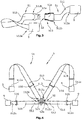
- the Fig. 3 1 shows a first exemplary embodiment of a belt device 51 of a patient restraint device 5 for tool-free locking on at least one locking device 3 of a patient transport device 1.
- the belt device 51 has two straps 512 and a buckle 52, wherein the two belts 512 each have a first end 512b and a second end 512a, wherein at the first end 512b of the belt 512, a first or second part of the buckle 52a, 52b arranged and wherein the two straps 512 each have at the second end 512a a second coupling element 9 for tool-free locking on a first coupling element 7 of a locking device 3 of a patient transport device 3.
- the first and second parts of the buckle 52a, 52b are adapted to each other in such a way that they are also connected and disconnected without tools.
- the illustrated Belt device 51 according to Fig. 3 For example, it can be locked to the first coupling elements 7 of a locking device 3 by means of the second coupling element 9 as a hip belt or as a leg strap in the area of patient transport device 1.
- the illustrated belt device 51 according to Fig. 3 to the locking device 3 according to the Fig. 1a and 1b are locked.
- the belt device 51 according to Fig. 3 has two second coupling elements 9, which are adapted to two first coupling elements 7 of the locking device 3.
- the second coupling elements 9 are configured in the form of a known from the automotive sector buckle.
- the locking between the first and second coupling elements 7, 9 can be separated without tools via a provided on the first or second coupling element 7.9 actuator (not shown).
- the strap 512 has a length 517 (not shown). Due to the different physical stature of the patients to be transported, different belt lengths 517 can be provided.
- the Fig. 4 shows a second embodiment of a belt device 51 of a patient restraint device 5, wherein the belt device 51 has a total of four straps 512, wherein it is the two upper straps 512 shown around shoulder straps 513 and the two lower straps 512 to hip straps 515.
- the shoulder straps 513 and the waist straps 515 each have at their first end 512b a first and / or second part of a buckle 52a, 52b.
- the first and second parts of the buckle 52a, 52b form a 4-point buckle in the illustrated embodiment.
- the shoulder straps 513 and the waist straps 515 each have at their second end 512a a second coupling element 9 for locking on a first Coupling element 7 of a locking device 3 on a patient transport device 1.
- both the waist straps 515 and the shoulder straps 513 each have a length adjustment device 516, via which the length of the hip and shoulder straps 513, 515 is infinitely adjustable.
- the illustrated straps 512 are each configured of a flat webbing 518.
- the Fig. 5 shows a patient transport device 1 in the configuration of a stretcher.
- the patient transport device 1 has a load-bearing basic structure 14 and a patient restraint device 5.
- the load-bearing basic structure 14 has a patient support device 17 and a frame structure 15.
- the patient restraint device 5 has in the illustrated embodiment, five locking devices 3 and three belt devices 51.
- the elements of the patient transport device 1, as well as the locking devices 3 and the belt devices 5 were shown separated from each other.
- the arrows between the aforementioned elements first clarify at which positions or locations of the basic structure 14 the individual locking devices 3 are fastened in the illustrated example.
- arrows illustrate how the belt devices 5 are connected to the locking devices 3 or locked thereto.
- the patient support device 17 has in the illustrated embodiment, a back portion 172, which is arranged opposite the frame structure 15 pivotally or tiltably. Furthermore, the patient support device 17 has a lower part 174. The lower part is in the illustrated embodiment, three-part over a seat support 174a and a two-part leg rest 174b with lower leg rest 175, and thigh support 176 formed. Two pairs of legs 151 are arranged on the frame structure 15, with the pairs of legs 151 each having a pair of rollers 153 at the end 152 facing away from the frame structure 15 at the bottom.
- the pairs of legs 151 are each pivotally connected to the frame structure 15 of the load-bearing base structure 14, wherein the pairs of legs 151 from a first unfolded locking position 154 (not shown) in a second, in the Fig. 5 shown unfolded locking position 155 are pivotable.
- the two locking devices 3 shown on the left of the patient transport device 1 each have a basic body 31 configured in the form of a circular cylinder, which are fastened to a crosspiece of the load-bearing basic structure 14 of the patient transport device 1.
- the remaining three locking devices 3 have in the illustrated embodiment, a base body 31 which is configured as a flat profile 311 and integrally with two first coupling elements 7.
- the left locking device 3 shown above the patient transport device 1 is screwed to the structure of the buttock support 174a or attached thereto.
- the middle locking device 3 is fastened to the base structure 14 in the region of the thigh support 176, as well as the right-most locking device 3 in the region of the lower leg support 175.
- a belt device 51 can be locked in each case via two first coupling elements 7 in conjunction with second coupling elements 9.
- the two belt devices 51 locked in the region of the thigh supports 175, 176 are in each case designed as a two-point belt in the sense of a leg belt.
- the belt device 51 In the area of the seat support 174a and the back part 172 is another belt device 51 locked to the other three locking devices 3.
- the belt device 51 is formed as a four-point belt with two shoulder straps 513 and two waist straps 515.
- the shoulder straps are through recesses 12 am in the FIG. 5 left end (upper end) of the back part 172 can be guided and locked to the first coupling elements 7 of the two locking devices 3 with a cylindrical base body 31.
- the two hip straps 515 are locked via second coupling elements 9 respectively to first coupling elements 7 of the locking device 3, which is fastened in the region of the buttock support 174a.
Landscapes
- Health & Medical Sciences (AREA)
- Life Sciences & Earth Sciences (AREA)
- Animal Behavior & Ethology (AREA)
- General Health & Medical Sciences (AREA)
- Public Health (AREA)
- Veterinary Medicine (AREA)
- Invalid Beds And Related Equipment (AREA)
Applications Claiming Priority (1)
| Application Number | Priority Date | Filing Date | Title |
|---|---|---|---|
| DE102017207909 | 2017-05-10 |
Publications (2)
| Publication Number | Publication Date |
|---|---|
| EP3400921A1 true EP3400921A1 (fr) | 2018-11-14 |
| EP3400921B1 EP3400921B1 (fr) | 2020-09-16 |
Family
ID=62134083
Family Applications (1)
| Application Number | Title | Priority Date | Filing Date |
|---|---|---|---|
| EP18170985.8A Active EP3400921B1 (fr) | 2017-05-10 | 2018-05-07 | Dispositif de blocage d'un dispositif de transport de patients ainsi que dispositif de ceinture pour un dispositif de retenue pour patient et système de transport de patients |
Country Status (2)
| Country | Link |
|---|---|
| EP (1) | EP3400921B1 (fr) |
| DK (1) | DK3400921T3 (fr) |
Cited By (1)
| Publication number | Priority date | Publication date | Assignee | Title |
|---|---|---|---|---|
| EP4124327A1 (fr) * | 2021-07-26 | 2023-02-01 | Hill-Rom Services, Inc. | Ensembles de support comprenant des supports de retenue pour appareils de support de personne et appareils de support de personne les comprenant |
Families Citing this family (1)
| Publication number | Priority date | Publication date | Assignee | Title |
|---|---|---|---|---|
| CA3224161A1 (fr) * | 2021-12-22 | 2023-06-29 | James Robert Tumavich | Systemes de confinement de patient destines a etre utilises avec des appareils de transport de patient |
Citations (7)
| Publication number | Priority date | Publication date | Assignee | Title |
|---|---|---|---|---|
| US2033779A (en) * | 1934-04-14 | 1936-03-10 | Tor Equipment Company Ltd | Ambulance stretcher |
| DE3321693A1 (de) * | 1983-06-15 | 1984-12-20 | Autoflug Gmbh, 2084 Rellingen | Krankenmoebel mit gurtsicherung |
| DE9015581U1 (de) | 1990-11-14 | 1991-01-31 | Stollenwerk Fabrik für Sanitätsausrüstungen Hans Stollenwerk & Cie GmbH & Co, 5000 Köln | Krankentrage |
| DE102005009682A1 (de) * | 2004-12-23 | 2006-07-06 | Detlev Fricke | Vorrichtung zur Aufnahme und Befestigung für rollbare Krankenhausbetten mit Liegendpatienten in Fahrzeugen, insbesondere Kraftfahrzeugen |
| DE202010014023U1 (de) | 2010-10-08 | 2010-12-30 | Kartsana Medical Gmbh | Untergestell für eine Transportvorrichtung und Transportvorrichtung |
| US20110056022A1 (en) * | 2007-01-17 | 2011-03-10 | Ayette Michael W | Restraint with shoulder harness adjuster |
| US20130269711A1 (en) | 2012-04-13 | 2013-10-17 | Ryan J. Porter | Modular support system. |
Family Cites Families (1)
| Publication number | Priority date | Publication date | Assignee | Title |
|---|---|---|---|---|
| CA2938848A1 (fr) * | 2014-02-10 | 2015-08-13 | Ferno-Washington, Inc. | Harnais de securite |
-
2018
- 2018-05-07 DK DK18170985.8T patent/DK3400921T3/da active
- 2018-05-07 EP EP18170985.8A patent/EP3400921B1/fr active Active
Patent Citations (7)
| Publication number | Priority date | Publication date | Assignee | Title |
|---|---|---|---|---|
| US2033779A (en) * | 1934-04-14 | 1936-03-10 | Tor Equipment Company Ltd | Ambulance stretcher |
| DE3321693A1 (de) * | 1983-06-15 | 1984-12-20 | Autoflug Gmbh, 2084 Rellingen | Krankenmoebel mit gurtsicherung |
| DE9015581U1 (de) | 1990-11-14 | 1991-01-31 | Stollenwerk Fabrik für Sanitätsausrüstungen Hans Stollenwerk & Cie GmbH & Co, 5000 Köln | Krankentrage |
| DE102005009682A1 (de) * | 2004-12-23 | 2006-07-06 | Detlev Fricke | Vorrichtung zur Aufnahme und Befestigung für rollbare Krankenhausbetten mit Liegendpatienten in Fahrzeugen, insbesondere Kraftfahrzeugen |
| US20110056022A1 (en) * | 2007-01-17 | 2011-03-10 | Ayette Michael W | Restraint with shoulder harness adjuster |
| DE202010014023U1 (de) | 2010-10-08 | 2010-12-30 | Kartsana Medical Gmbh | Untergestell für eine Transportvorrichtung und Transportvorrichtung |
| US20130269711A1 (en) | 2012-04-13 | 2013-10-17 | Ryan J. Porter | Modular support system. |
Cited By (2)
| Publication number | Priority date | Publication date | Assignee | Title |
|---|---|---|---|---|
| EP4124327A1 (fr) * | 2021-07-26 | 2023-02-01 | Hill-Rom Services, Inc. | Ensembles de support comprenant des supports de retenue pour appareils de support de personne et appareils de support de personne les comprenant |
| US12343279B2 (en) | 2021-07-26 | 2025-07-01 | Hill-Rom Services, Inc. | Bracket assemblies including restraint brackets for person support apparatuses and person support apparatuses comprising the same |
Also Published As
| Publication number | Publication date |
|---|---|
| DK3400921T3 (da) | 2020-12-07 |
| EP3400921B1 (fr) | 2020-09-16 |
Similar Documents
| Publication | Publication Date | Title |
|---|---|---|
| EP0030211A2 (fr) | Mobilier de couchage | |
| DE3643367A1 (de) | Einrichtung zum ausueben einer spinalen streckkraft | |
| DE102015118955B4 (de) | Sitzassistent zur Mobilisation von Patienten | |
| DE2211015A1 (de) | Tragbahre zum Transport von Personen, insbesondere mit'Wirbelsäulenverletzungen oder Brüchen des Oberschenkelhalsknochens | |
| EP3400921B1 (fr) | Dispositif de blocage d'un dispositif de transport de patients ainsi que dispositif de ceinture pour un dispositif de retenue pour patient et système de transport de patients | |
| EP3287112B1 (fr) | Lit thérapeutique | |
| WO2008113522A1 (fr) | Poussette présentant un dispositif de fixation et de réglage de la sangle | |
| WO2018019637A1 (fr) | Orthèse | |
| EP0713692B1 (fr) | Dispositif pour la reéducation de la marche pour personnes handicapées | |
| DE19930103C1 (de) | Dynamische Sitzschale | |
| DE69323405T2 (de) | Vorrichtung zum Transportieren einer behinderten Person | |
| DE102007029572B4 (de) | Haltevorrichtung zum Entlasten der Wirbelsäule in der Sitzposition | |
| DE202012005361U1 (de) | Vorrichtung zum Bewegen eines Fahrzeugs | |
| DE102019107910A1 (de) | Extensions-Ansteckvorrichtung | |
| DE102018111654B4 (de) | Krankentransportvorrichtung, insbesondere für einen Kranken- oder Rettungstransportwagen | |
| DE202018003805U1 (de) | Dynamisches Rückenelement für einen Rollstuhl, einem mit diesem Rückenelement ausgestatteten Rollstuhl und eine Anordnung eines Rückenelementes in einem Rollstuhl | |
| EP1997538A1 (fr) | Harnais | |
| AT405131B (de) | Bergetuch | |
| DE60037591T2 (de) | Steifschalige schiene | |
| DE19942444C1 (de) | Sitzeinrichtung zum hängenden Befördern von Personen | |
| DE102009038838B4 (de) | Crashrettungsvorrichtung zur Anbringung an einer Schleiftrage | |
| DE102007012557B3 (de) | Bauchspanngurt | |
| DE102020132341B4 (de) | Vakuummatratze | |
| DE102023122192A1 (de) | Vorrichtung zur Anbindung einer Last an den Rücken einer Person | |
| DE10049302B4 (de) | Tragesystem |
Legal Events
| Date | Code | Title | Description |
|---|---|---|---|
| PUAI | Public reference made under article 153(3) epc to a published international application that has entered the european phase |
Free format text: ORIGINAL CODE: 0009012 |
|
| STAA | Information on the status of an ep patent application or granted ep patent |
Free format text: STATUS: THE APPLICATION HAS BEEN PUBLISHED |
|
| AK | Designated contracting states |
Kind code of ref document: A1 Designated state(s): AL AT BE BG CH CY CZ DE DK EE ES FI FR GB GR HR HU IE IS IT LI LT LU LV MC MK MT NL NO PL PT RO RS SE SI SK SM TR |
|
| AX | Request for extension of the european patent |
Extension state: BA ME |
|
| STAA | Information on the status of an ep patent application or granted ep patent |
Free format text: STATUS: REQUEST FOR EXAMINATION WAS MADE |
|
| 17P | Request for examination filed |
Effective date: 20190508 |
|
| RBV | Designated contracting states (corrected) |
Designated state(s): AL AT BE BG CH CY CZ DE DK EE ES FI FR GB GR HR HU IE IS IT LI LT LU LV MC MK MT NL NO PL PT RO RS SE SI SK SM TR |
|
| RIC1 | Information provided on ipc code assigned before grant |
Ipc: A61G 1/044 20060101AFI20190726BHEP Ipc: A61G 1/056 20060101ALN20190726BHEP Ipc: A61G 1/02 20060101ALN20190726BHEP |
|
| RIC1 | Information provided on ipc code assigned before grant |
Ipc: A61G 1/02 20060101ALN20190912BHEP Ipc: A61G 1/056 20060101ALN20190912BHEP Ipc: A61G 1/044 20060101AFI20190912BHEP |
|
| STAA | Information on the status of an ep patent application or granted ep patent |
Free format text: STATUS: EXAMINATION IS IN PROGRESS |
|
| 17Q | First examination report despatched |
Effective date: 20200113 |
|
| RIC1 | Information provided on ipc code assigned before grant |
Ipc: A61G 1/02 20060101ALN20200327BHEP Ipc: A61G 1/056 20060101ALN20200327BHEP Ipc: A61G 1/044 20060101AFI20200327BHEP |
|
| GRAP | Despatch of communication of intention to grant a patent |
Free format text: ORIGINAL CODE: EPIDOSNIGR1 |
|
| STAA | Information on the status of an ep patent application or granted ep patent |
Free format text: STATUS: GRANT OF PATENT IS INTENDED |
|
| RIC1 | Information provided on ipc code assigned before grant |
Ipc: A61G 1/02 20060101ALN20200605BHEP Ipc: A61G 1/044 20060101AFI20200605BHEP Ipc: A61G 1/056 20060101ALN20200605BHEP |
|
| INTG | Intention to grant announced |
Effective date: 20200622 |
|
| GRAS | Grant fee paid |
Free format text: ORIGINAL CODE: EPIDOSNIGR3 |
|
| GRAA | (expected) grant |
Free format text: ORIGINAL CODE: 0009210 |
|
| STAA | Information on the status of an ep patent application or granted ep patent |
Free format text: STATUS: THE PATENT HAS BEEN GRANTED |
|
| AK | Designated contracting states |
Kind code of ref document: B1 Designated state(s): AL AT BE BG CH CY CZ DE DK EE ES FI FR GB GR HR HU IE IS IT LI LT LU LV MC MK MT NL NO PL PT RO RS SE SI SK SM TR |
|
| REG | Reference to a national code |
Ref country code: GB Ref legal event code: FG4D Free format text: NOT ENGLISH |
|
| REG | Reference to a national code |
Ref country code: CH Ref legal event code: EP |
|
| REG | Reference to a national code |
Ref country code: DE Ref legal event code: R096 Ref document number: 502018002447 Country of ref document: DE |
|
| REG | Reference to a national code |
Ref country code: IE Ref legal event code: FG4D Free format text: LANGUAGE OF EP DOCUMENT: GERMAN |
|
| REG | Reference to a national code |
Ref country code: AT Ref legal event code: REF Ref document number: 1313471 Country of ref document: AT Kind code of ref document: T Effective date: 20201015 |
|
| REG | Reference to a national code |
Ref country code: CH Ref legal event code: NV Representative=s name: ISLER AND PEDRAZZINI AG, CH |
|
| REG | Reference to a national code |
Ref country code: DK Ref legal event code: T3 Effective date: 20201203 |
|
| REG | Reference to a national code |
Ref country code: NL Ref legal event code: FP |
|
| PG25 | Lapsed in a contracting state [announced via postgrant information from national office to epo] |
Ref country code: HR Free format text: LAPSE BECAUSE OF FAILURE TO SUBMIT A TRANSLATION OF THE DESCRIPTION OR TO PAY THE FEE WITHIN THE PRESCRIBED TIME-LIMIT Effective date: 20200916 Ref country code: SE Free format text: LAPSE BECAUSE OF FAILURE TO SUBMIT A TRANSLATION OF THE DESCRIPTION OR TO PAY THE FEE WITHIN THE PRESCRIBED TIME-LIMIT Effective date: 20200916 Ref country code: BG Free format text: LAPSE BECAUSE OF FAILURE TO SUBMIT A TRANSLATION OF THE DESCRIPTION OR TO PAY THE FEE WITHIN THE PRESCRIBED TIME-LIMIT Effective date: 20201216 Ref country code: FI Free format text: LAPSE BECAUSE OF FAILURE TO SUBMIT A TRANSLATION OF THE DESCRIPTION OR TO PAY THE FEE WITHIN THE PRESCRIBED TIME-LIMIT Effective date: 20200916 Ref country code: NO Free format text: LAPSE BECAUSE OF FAILURE TO SUBMIT A TRANSLATION OF THE DESCRIPTION OR TO PAY THE FEE WITHIN THE PRESCRIBED TIME-LIMIT Effective date: 20201216 Ref country code: GR Free format text: LAPSE BECAUSE OF FAILURE TO SUBMIT A TRANSLATION OF THE DESCRIPTION OR TO PAY THE FEE WITHIN THE PRESCRIBED TIME-LIMIT Effective date: 20201217 |
|
| PG25 | Lapsed in a contracting state [announced via postgrant information from national office to epo] |
Ref country code: LV Free format text: LAPSE BECAUSE OF FAILURE TO SUBMIT A TRANSLATION OF THE DESCRIPTION OR TO PAY THE FEE WITHIN THE PRESCRIBED TIME-LIMIT Effective date: 20200916 Ref country code: RS Free format text: LAPSE BECAUSE OF FAILURE TO SUBMIT A TRANSLATION OF THE DESCRIPTION OR TO PAY THE FEE WITHIN THE PRESCRIBED TIME-LIMIT Effective date: 20200916 |
|
| REG | Reference to a national code |
Ref country code: LT Ref legal event code: MG4D |
|
| PG25 | Lapsed in a contracting state [announced via postgrant information from national office to epo] |
Ref country code: LT Free format text: LAPSE BECAUSE OF FAILURE TO SUBMIT A TRANSLATION OF THE DESCRIPTION OR TO PAY THE FEE WITHIN THE PRESCRIBED TIME-LIMIT Effective date: 20200916 Ref country code: SM Free format text: LAPSE BECAUSE OF FAILURE TO SUBMIT A TRANSLATION OF THE DESCRIPTION OR TO PAY THE FEE WITHIN THE PRESCRIBED TIME-LIMIT Effective date: 20200916 Ref country code: PT Free format text: LAPSE BECAUSE OF FAILURE TO SUBMIT A TRANSLATION OF THE DESCRIPTION OR TO PAY THE FEE WITHIN THE PRESCRIBED TIME-LIMIT Effective date: 20210118 Ref country code: RO Free format text: LAPSE BECAUSE OF FAILURE TO SUBMIT A TRANSLATION OF THE DESCRIPTION OR TO PAY THE FEE WITHIN THE PRESCRIBED TIME-LIMIT Effective date: 20200916 Ref country code: CZ Free format text: LAPSE BECAUSE OF FAILURE TO SUBMIT A TRANSLATION OF THE DESCRIPTION OR TO PAY THE FEE WITHIN THE PRESCRIBED TIME-LIMIT Effective date: 20200916 Ref country code: EE Free format text: LAPSE BECAUSE OF FAILURE TO SUBMIT A TRANSLATION OF THE DESCRIPTION OR TO PAY THE FEE WITHIN THE PRESCRIBED TIME-LIMIT Effective date: 20200916 |
|
| PG25 | Lapsed in a contracting state [announced via postgrant information from national office to epo] |
Ref country code: IS Free format text: LAPSE BECAUSE OF FAILURE TO SUBMIT A TRANSLATION OF THE DESCRIPTION OR TO PAY THE FEE WITHIN THE PRESCRIBED TIME-LIMIT Effective date: 20210116 Ref country code: PL Free format text: LAPSE BECAUSE OF FAILURE TO SUBMIT A TRANSLATION OF THE DESCRIPTION OR TO PAY THE FEE WITHIN THE PRESCRIBED TIME-LIMIT Effective date: 20200916 Ref country code: AL Free format text: LAPSE BECAUSE OF FAILURE TO SUBMIT A TRANSLATION OF THE DESCRIPTION OR TO PAY THE FEE WITHIN THE PRESCRIBED TIME-LIMIT Effective date: 20200916 Ref country code: ES Free format text: LAPSE BECAUSE OF FAILURE TO SUBMIT A TRANSLATION OF THE DESCRIPTION OR TO PAY THE FEE WITHIN THE PRESCRIBED TIME-LIMIT Effective date: 20200916 |
|
| REG | Reference to a national code |
Ref country code: DE Ref legal event code: R097 Ref document number: 502018002447 Country of ref document: DE |
|
| PG25 | Lapsed in a contracting state [announced via postgrant information from national office to epo] |
Ref country code: SK Free format text: LAPSE BECAUSE OF FAILURE TO SUBMIT A TRANSLATION OF THE DESCRIPTION OR TO PAY THE FEE WITHIN THE PRESCRIBED TIME-LIMIT Effective date: 20200916 |
|
| PLBE | No opposition filed within time limit |
Free format text: ORIGINAL CODE: 0009261 |
|
| STAA | Information on the status of an ep patent application or granted ep patent |
Free format text: STATUS: NO OPPOSITION FILED WITHIN TIME LIMIT |
|
| 26N | No opposition filed |
Effective date: 20210617 |
|
| PG25 | Lapsed in a contracting state [announced via postgrant information from national office to epo] |
Ref country code: SI Free format text: LAPSE BECAUSE OF FAILURE TO SUBMIT A TRANSLATION OF THE DESCRIPTION OR TO PAY THE FEE WITHIN THE PRESCRIBED TIME-LIMIT Effective date: 20200916 |
|
| PG25 | Lapsed in a contracting state [announced via postgrant information from national office to epo] |
Ref country code: MC Free format text: LAPSE BECAUSE OF FAILURE TO SUBMIT A TRANSLATION OF THE DESCRIPTION OR TO PAY THE FEE WITHIN THE PRESCRIBED TIME-LIMIT Effective date: 20200916 |
|
| PGFP | Annual fee paid to national office [announced via postgrant information from national office to epo] |
Ref country code: LU Payment date: 20220518 Year of fee payment: 5 Ref country code: IT Payment date: 20220531 Year of fee payment: 5 Ref country code: IE Payment date: 20220517 Year of fee payment: 5 Ref country code: FR Payment date: 20220523 Year of fee payment: 5 |
|
| PGFP | Annual fee paid to national office [announced via postgrant information from national office to epo] |
Ref country code: MT Payment date: 20220520 Year of fee payment: 5 |
|
| P01 | Opt-out of the competence of the unified patent court (upc) registered |
Effective date: 20230303 |
|
| PG25 | Lapsed in a contracting state [announced via postgrant information from national office to epo] |
Ref country code: CY Free format text: LAPSE BECAUSE OF FAILURE TO SUBMIT A TRANSLATION OF THE DESCRIPTION OR TO PAY THE FEE WITHIN THE PRESCRIBED TIME-LIMIT Effective date: 20200916 |
|
| PG25 | Lapsed in a contracting state [announced via postgrant information from national office to epo] |
Ref country code: HU Free format text: LAPSE BECAUSE OF FAILURE TO SUBMIT A TRANSLATION OF THE DESCRIPTION OR TO PAY THE FEE WITHIN THE PRESCRIBED TIME-LIMIT; INVALID AB INITIO Effective date: 20180507 |
|
| PG25 | Lapsed in a contracting state [announced via postgrant information from national office to epo] |
Ref country code: LU Free format text: LAPSE BECAUSE OF NON-PAYMENT OF DUE FEES Effective date: 20230507 |
|
| REG | Reference to a national code |
Ref country code: IE Ref legal event code: MM4A |
|
| PG25 | Lapsed in a contracting state [announced via postgrant information from national office to epo] |
Ref country code: IE Free format text: LAPSE BECAUSE OF NON-PAYMENT OF DUE FEES Effective date: 20230507 |
|
| PG25 | Lapsed in a contracting state [announced via postgrant information from national office to epo] |
Ref country code: MK Free format text: LAPSE BECAUSE OF FAILURE TO SUBMIT A TRANSLATION OF THE DESCRIPTION OR TO PAY THE FEE WITHIN THE PRESCRIBED TIME-LIMIT Effective date: 20200916 Ref country code: IT Free format text: LAPSE BECAUSE OF NON-PAYMENT OF DUE FEES Effective date: 20230507 Ref country code: IE Free format text: LAPSE BECAUSE OF NON-PAYMENT OF DUE FEES Effective date: 20230507 |
|
| PG25 | Lapsed in a contracting state [announced via postgrant information from national office to epo] |
Ref country code: FR Free format text: LAPSE BECAUSE OF NON-PAYMENT OF DUE FEES Effective date: 20230531 |
|
| PG25 | Lapsed in a contracting state [announced via postgrant information from national office to epo] |
Ref country code: TR Free format text: LAPSE BECAUSE OF FAILURE TO SUBMIT A TRANSLATION OF THE DESCRIPTION OR TO PAY THE FEE WITHIN THE PRESCRIBED TIME-LIMIT Effective date: 20200916 |
|
| PGFP | Annual fee paid to national office [announced via postgrant information from national office to epo] |
Ref country code: NL Payment date: 20250522 Year of fee payment: 8 |
|
| PGFP | Annual fee paid to national office [announced via postgrant information from national office to epo] |
Ref country code: DE Payment date: 20250428 Year of fee payment: 8 |
|
| PGFP | Annual fee paid to national office [announced via postgrant information from national office to epo] |
Ref country code: GB Payment date: 20250522 Year of fee payment: 8 Ref country code: DK Payment date: 20250521 Year of fee payment: 8 |
|
| PGFP | Annual fee paid to national office [announced via postgrant information from national office to epo] |
Ref country code: BE Payment date: 20250520 Year of fee payment: 8 |
|
| PGFP | Annual fee paid to national office [announced via postgrant information from national office to epo] |
Ref country code: CH Payment date: 20250601 Year of fee payment: 8 |
|
| PGFP | Annual fee paid to national office [announced via postgrant information from national office to epo] |
Ref country code: AT Payment date: 20250519 Year of fee payment: 8 |