EP3400922B1 - Dispositif absorbant les chocs sur la partie arrière d'un véhicule équipé d'une rampe pliable - Google Patents
Dispositif absorbant les chocs sur la partie arrière d'un véhicule équipé d'une rampe pliable Download PDFInfo
- Publication number
- EP3400922B1 EP3400922B1 EP17000795.9A EP17000795A EP3400922B1 EP 3400922 B1 EP3400922 B1 EP 3400922B1 EP 17000795 A EP17000795 A EP 17000795A EP 3400922 B1 EP3400922 B1 EP 3400922B1
- Authority
- EP
- European Patent Office
- Prior art keywords
- vehicle
- brace
- interlocking
- main
- arm
- Prior art date
- Legal status (The legal status is an assumption and is not a legal conclusion. Google has not performed a legal analysis and makes no representation as to the accuracy of the status listed.)
- Active
Links
Images




Classifications
-
- A—HUMAN NECESSITIES
- A61—MEDICAL OR VETERINARY SCIENCE; HYGIENE
- A61G—TRANSPORT, PERSONAL CONVEYANCES, OR ACCOMMODATION SPECIALLY ADAPTED FOR PATIENTS OR DISABLED PERSONS; OPERATING TABLES OR CHAIRS; CHAIRS FOR DENTISTRY; FUNERAL DEVICES
- A61G3/00—Ambulance aspects of vehicles; Vehicles with special provisions for transporting patients or disabled persons, or their personal conveyances, e.g. for facilitating access of, or for loading, wheelchairs
- A61G3/02—Loading or unloading personal conveyances; Facilitating access of patients or disabled persons to, or exit from, vehicles
- A61G3/06—Transfer using ramps, lifts or the like
- A61G3/061—Transfer using ramps, lifts or the like using ramps
Definitions
- the invention concerns a device absorbing impact on the rear part of a vehicle equipped with a foldable ramp designed particularly to move manual and electric wheelchairs into and out of a vehicle through the rear door.
- the foldable ramp takes up as little space inside the vehicle as possible and that normal operation of the vehicle is possible when the ramp is folded. It is also necessary to make the control of folding of the ramp in and out simple, safe and physically undemanding even for persons who are not physically strong or who may have certain limitations due to their health condition or age.
- the entry platform is attached to the edge of the floor well by means of a pivotal hinge. If the platform is made of one part, after the wheelchair drives into the vehicle, the platform is lifted to a vertical transport position between the wheelchair and the door and it is locked with a safety latch. After the wheelchair moves out of the vehicle, the platform is folded into the vehicle, while the pivotal hinge is moved into another height configuration, and the platform covers the floor well. In this position there is a luggage room created in the rear part of the vehicle corresponding to common vehicles, with no limitation of access. If the platform is made of two parts there is no need to change the height configuration of the pivotal hinge. In the entry position and in the transport position both parts are in an interlocking position. After the wheelchair moves out of the vehicle the lock is released and the second part of the platform is folded on the floor well, while the first part creates the rear face.
- the trajectory of this movement is defined by guiding grooves created in the tiltable side parts and in the carriers and by pins that engage into the guiding grooves.
- the vertical position of the entry platform is called the transport position. The rear door in this position is closed and the wheelchair with the transported person is located and secured in front of the entry platform arrested in the transport position.
- This invention seeks to eliminate the shortcomings described above and to create a device for efficient absorption of impacts on the rear part of vehicles provided with a foldable ramp.
- the device consists of two interlocking modules.
- Each interlocking module is situated between the end of the horizontal brace of the bottom part of the foldable ramp and the adjoining main bearer.
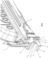
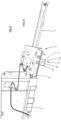
- Each interlocking module consists of a fixed interlocking element connected with the main bearer and a moving interlocking element connected with the brace and moving with it, while in the transport position the bottom parts of the interlocking elements mutually snap in.
- the interlocking module thus forms a firm connection between the main bearers and the brace, horizontally in the driving direction of the vehicle and also in the direction perpendicular to it.
- the force of an impact on the rear side is transferred via the interlocking modules to the main bearers in the driving direction and, at the same time, the interlocking modules prevent deformation of the body in the direction perpendicular to the driving direction, i.e. from the center to the sides.
- the fixed interlocking element is not connected directly to the main bearer but to a bracket connected with the main bearer.
- the bracket may also have an additional function as we will describe below.
- the fixed interlocking element consists of a dowel pin linked with a retainer and the movable interlocking element consists of the side wall of the brace provided with a groove and a stop, while in the transport position the dowel pin engages in the groove and rests on the stop and the retainer falls behind the side wall inside the brace.
- the brace is made out of a hollow steel U-shaped section with its open side towards the bottom part of the foldable ramp.
- the vertical retainer is L-shaped, its one arm forming the retainer and the other arm is attached to the bracket connected to the main bearer.
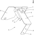
- bracket has the base attachable to the end of the main bearer and its arm is perpendicular to the base in the extended direction of the main bearer towards the end of the brace, while the fixed interlocking element is attached to the arm of the bracket.
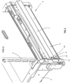
- the vehicle 1 is in its rear part, i.e. in the luggage compartment, provided with a lowered floor well 2 which is embedded in the floor between two main bearers 3, 3' arranged lengthwise under the sides of the vehicle 1 and under the rear wheel houses. Ends of the main bearers 3 , 3' are linked with deformation elements 20 that carry a left segment of the bumper 23 and a right segment of the bumper 23' .
- a platform-like bottom part 6 of the foldable ramp 4 is pivotally attached on hinges to the rear edge of the lowered floor well 2.
- the bottom part 6 has tiltable side parts revolving on hinges and thus the bottom part 6 moves from the transport position A to the entry position B and vice versa.
- the tiltable side parts are provided with moving carriers connected with the entry platform 5.
- the foldable ramp 4 is also provided with a system of pulleys that conduct ropes attached to springs to ensure smooth movement of the foldable ramp 4 between the individual working positions.
- the bottom part 6 of the foldable ramp 4 is provided with a horizontal brace 7.
- the brace 7 is supposed to retain an impact on the rear part of the vehicle 1 and it consists of a steel "U" section with its open side towards the bottom part 6 of the foldable ramp 4 and it stretches all along its length.
- the brace 7 can have a number of other possible embodiments.
- interlocking modules that arrest the brace 7 in relation to the main bearers 3, 3' in the transport position A and create a firm connection between them that prevents displacement of the brace 7 and the whole bottom part 6 inside towards the front part of the vehicle 1 during impact from the back.
- the connection is also firm in the perpendicular direction to the vehicle's driving direction 1 and thus it also prevents transverse deformation in the direction from the center to the sides.
- FIG. 1 through 9 show only one interlocking module, specifically at the left main bearer 3
- the other interlocking module at the right main bearer 3' is designed identically, only as the mirror image.
- the connection of the interlocking element 8 with the main bearers 3 , 3' is implemented with a bracket 15 .
- the bracket 15 is a die stamping with a flat base 16 attached to the end of the main bearer 3 , 3' .
- the base 16 forms the right angle with the flat arm 17 that runs toward the back in the extended direction of the main bearer 3 , 3' .
- the fixed interlocking element 8 made of an L-section with the retainer 11 and the dowel pin 10 is welded to the arm 17.
- the bracket 1 5 is not indispensable but it is advantageous, among other things, also for placement of the deformation element 20 .
- the fixed interlocking element 8 may be attached to the main bearer 3, 3' directly or indirectly via a simple arm or strut.
- the device under this invention is used in vehicles equipped with a rear foldable ramp.
Landscapes
- Health & Medical Sciences (AREA)
- Public Health (AREA)
- Life Sciences & Earth Sciences (AREA)
- Animal Behavior & Ethology (AREA)
- General Health & Medical Sciences (AREA)
- Veterinary Medicine (AREA)
- Vehicle Step Arrangements And Article Storage (AREA)
- Body Structure For Vehicles (AREA)
Claims (7)
- Véhicule (1) comprenant un dispositif absorbant les chocs sur la partie arrière du véhicule (1) pourvu d'un puit à plancher abaissé (2) disposé entre deux supports principaux (3, 3') et d'une rampe pliable (4) constitué d'une plate-forme d'entrée (5) et d'une partie inférieure (6) portant la plate-forme d'entrée (5), où la partie inférieure (6) est fixée de manière pivotante au bord du puits à plancher abaissé (2) et qui peut se déplacer entre un position de transport (A), lorsqu'il est placé verticalement à l'intérieur du véhicule (1) et verrouillé par un mécanisme de verrouillage (10, 11) en position de transport (A), et une position d'entrée (B), lorsqu'il est placé à l'intérieur du véhicule (1), tandis que la partie inférieure (6) est munie d'au moins une entretoise horizontale (7) caractérisé en ce que le dispositif absorbant les chocs est constitué de deux modules de verrouillage, chacun des modules de verrouillage est disposé entre l'extrémité de l'entretoise horizontale (7) et le support principal adjacent (3, 3'), chaque module de verrouillage est constitué d'un élément de verrouillage fixe (8) relié au support principal (3, 3') et d'un élément de verrouillage mobile (9) relié à l'entretoise (7), tandis qu'en position de transport (A), les parties inférieures (6), les éléments de verrouillage (8, 9) s'enclenchent mutuellement et le module de verrouillage forme une liaison solide entre les supports principaux (3, 3') avec l'entretoise (7), horizontalement dans la direction de marche du véhicule (1) et dans la direction perpendiculaire à la direction de marche du véhicule (1).
- Véhicule (1) selon la revendication 1 caractérisé en ce que l'élément de verrouillage fixe (8) est fixé au support (15) relié au support principal (3, 3').
- Véhicule (1) selon la revendication 1 caractérisé en ce que l'élément de verrouillage fixe (8) comporte une goupille (10) avec un dispositif de retenue (11), l'élément de verrouillage mobile (9) comporte une paroi latérale (12) de l'entretoise (7) pourvue d'une rainure (13) et d'une butée (14), tandis qu'en la position de transport (A), la goupille (10) s'engage dans la rainure (13) et repose sur la butée (14) et le dispositif de retenue (11) tombe derrière la paroi latérale (12) à l'intérieur de l'entretoise (7).
- Véhicule (1) selon l'une des revendications 1 à 3 caractérisé en ce que l'entretoise (7) est constituée d'un profilé d'acier creux en forme de U dont le côté ouvert est orienté vers la partie inférieure (6) de la rampe pliable (4).
- Véhicule (1) selon la revendication 3 caractérisé en ce que le dispositif de retenue vertical (11) est en forme de L, son bras forme le dispositif de retenue (11) et l'autre bras est fixé au support (15) relié au support principal (3, 3').
- Le véhicule (1) selon la revendication 2 ou 5 caractérisé en ce que le support (15) comporte une base (16) qui peut être fixée à l'extrémité du support principal (3, 3') et un bras (17) perpendiculaire à la base (16) dans la direction d'extension du support principal (3, 3') vers l'extrémité de l'entretoise (7), tandis que l'élément de verrouillage fixe (8) est fixé au bras (17).
- Véhicule (1) selon la revendication 6 caractérisé en ce que le bras (17) est pourvu d'un attelage avant (18) avec des ouvertures (19) disposé parallèlement à la base (16), d'un attelage supérieur (21) avec des ouvertures (22) disposé perpendiculairement à la base (16), et entre l'attelage avant (18) et la base (16) se trouve un élément de déformation (20) fixé aux attelages (18, 21) avec des vis dans les ouvertures (19, 22).
Priority Applications (3)
| Application Number | Priority Date | Filing Date | Title |
|---|---|---|---|
| ES17000795T ES2986842T3 (es) | 2017-05-09 | 2017-05-09 | Dispositivo de absorción de impactos en la parte trasera de un vehículo equipado con una rampa plegable |
| EP17000795.9A EP3400922B1 (fr) | 2017-05-09 | 2017-05-09 | Dispositif absorbant les chocs sur la partie arrière d'un véhicule équipé d'une rampe pliable |
| PL17000795.9T PL3400922T3 (pl) | 2017-05-09 | 2017-05-09 | Urządzenie pochłaniające uderzenia w tylną część pojazdu wyposażonego w składaną rampę |
Applications Claiming Priority (1)
| Application Number | Priority Date | Filing Date | Title |
|---|---|---|---|
| EP17000795.9A EP3400922B1 (fr) | 2017-05-09 | 2017-05-09 | Dispositif absorbant les chocs sur la partie arrière d'un véhicule équipé d'une rampe pliable |
Publications (3)
| Publication Number | Publication Date |
|---|---|
| EP3400922A1 EP3400922A1 (fr) | 2018-11-14 |
| EP3400922B1 true EP3400922B1 (fr) | 2024-07-03 |
| EP3400922C0 EP3400922C0 (fr) | 2024-07-03 |
Family
ID=58707275
Family Applications (1)
| Application Number | Title | Priority Date | Filing Date |
|---|---|---|---|
| EP17000795.9A Active EP3400922B1 (fr) | 2017-05-09 | 2017-05-09 | Dispositif absorbant les chocs sur la partie arrière d'un véhicule équipé d'une rampe pliable |
Country Status (3)
| Country | Link |
|---|---|
| EP (1) | EP3400922B1 (fr) |
| ES (1) | ES2986842T3 (fr) |
| PL (1) | PL3400922T3 (fr) |
Citations (1)
| Publication number | Priority date | Publication date | Assignee | Title |
|---|---|---|---|---|
| WO2013105313A1 (fr) * | 2012-01-10 | 2013-07-18 | トヨタ車体株式会社 | Équipement de rampe pour véhicule |
Family Cites Families (8)
| Publication number | Priority date | Publication date | Assignee | Title |
|---|---|---|---|---|
| EP0390431A3 (fr) | 1989-03-31 | 1991-05-08 | Rodney John Brotherwood | Véhicule transportant un passager |
| US5137413A (en) | 1990-10-05 | 1992-08-11 | Paul Ressler | Expanded interior space and improved access mini-van |
| GB9303025D0 (en) | 1993-02-16 | 1993-03-31 | Brotherhood Rodney J | Improvements in passenger carrying vehicles |
| GB9513577D0 (en) | 1995-07-04 | 1995-09-06 | Brotherwood Rodney J | Improvements in passenger carrying vehicles |
| DE29814814U1 (de) | 1998-08-11 | 1998-11-12 | Maubach, Martin, 14057 Berlin | Multifunktionale Rampe an Fahrzeugen als Einfahrthilfe für Rollstuhlfahrer |
| WO2003059685A2 (fr) | 2002-01-15 | 2003-07-24 | The Braun Corporation | Systeme d'acces pour fauteuil roulant de vehicule |
| CZ18846U1 (cs) * | 2008-07-08 | 2008-08-28 | Api Cz S.R.O. | Výklopná nájezdová rampa pro nájezd invalidního vozíku s pasažérem do vozidla |
| DE202013002152U1 (de) * | 2013-03-07 | 2014-06-11 | Amf-Bruns Gmbh & Co. Kg | Rampensystem zum Einbau in ein Fahrzeug |
-
2017
- 2017-05-09 ES ES17000795T patent/ES2986842T3/es active Active
- 2017-05-09 PL PL17000795.9T patent/PL3400922T3/pl unknown
- 2017-05-09 EP EP17000795.9A patent/EP3400922B1/fr active Active
Patent Citations (1)
| Publication number | Priority date | Publication date | Assignee | Title |
|---|---|---|---|---|
| WO2013105313A1 (fr) * | 2012-01-10 | 2013-07-18 | トヨタ車体株式会社 | Équipement de rampe pour véhicule |
Also Published As
| Publication number | Publication date |
|---|---|
| EP3400922A1 (fr) | 2018-11-14 |
| EP3400922C0 (fr) | 2024-07-03 |
| PL3400922T3 (pl) | 2024-10-28 |
| ES2986842T3 (es) | 2024-11-12 |
Similar Documents
| Publication | Publication Date | Title |
|---|---|---|
| EP2293755B1 (fr) | Rampe pliable permettant à un passager invalide en chaise roulante d'entrer dans un véhicule | |
| EP3400924B1 (fr) | Rampe pliable pour l'accès d'un fauteuil roulant à la porte arrière d'une voiture de tourisme | |
| KR100218753B1 (ko) | 개선된 수직으로 이동하는 자동차 미닫이문 | |
| US5110252A (en) | Wheelchair lift for transit vehicles having elevated passenger compartment floor | |
| US6461097B1 (en) | Wheelchair lift device | |
| US12239585B2 (en) | Movable baseplate cover and inboard barrier gate of a lift system for a motorized vehicle | |
| EP3606489B1 (fr) | Système de fixation de fauteuil roulant réglable en hauteur | |
| EP3220868B1 (fr) | Système de rampe rétractable pour véhicule motorisé | |
| US20150217612A1 (en) | Environment Adaptive Electric Vehicle with Lock On Security and Control Saddle | |
| US7207765B1 (en) | Electrically-actuated transfer seat | |
| EP1767394B1 (fr) | Aménagement de siège | |
| CA2411958A1 (fr) | Ensemble rampe escamotable | |
| US6612802B2 (en) | Electrically-actuated transfer seat | |
| EP3400922A1 (fr) | Dispositif absorbant les chocs sur la partie arrière d'un véhicule équipé d'une rampe pliable | |
| EP3295912A1 (fr) | Ensemble mobile pour un élévateur à plate-forme pliable pour fauteuil roulant | |
| US1947980A (en) | Collapsible seat for vehicles | |
| EP4072897B1 (fr) | Siège de véhicule | |
| CN105142947A (zh) | 车辆 | |
| EP1561636B1 (fr) | Barre de sécurité | |
| EP4474212B1 (fr) | Unité de structure pour un véhicule terrestre, à siège rabattable | |
| US20050066586A1 (en) | Isolation unit and method of use for securing inmates | |
| WO2007113501A1 (fr) | Soulévateur amélioré | |
| JP3010459U (ja) | 車両用昇降装置におけるプラットホームのロック装置およびプラットホーム乗車者頭高の低減装置 | |
| JP3170718U (ja) | 自動車の座席構造 | |
| CA2964788C (fr) | Systeme de rampe retractable pour vehicule motorise |
Legal Events
| Date | Code | Title | Description |
|---|---|---|---|
| PUAI | Public reference made under article 153(3) epc to a published international application that has entered the european phase |
Free format text: ORIGINAL CODE: 0009012 |
|
| STAA | Information on the status of an ep patent application or granted ep patent |
Free format text: STATUS: REQUEST FOR EXAMINATION WAS MADE |
|
| 17P | Request for examination filed |
Effective date: 20170509 |
|
| AK | Designated contracting states |
Kind code of ref document: A1 Designated state(s): AL AT BE BG CH CY CZ DE DK EE ES FI FR GB GR HR HU IE IS IT LI LT LU LV MC MK MT NL NO PL PT RO RS SE SI SK SM TR |
|
| AX | Request for extension of the european patent |
Extension state: BA ME |
|
| STAA | Information on the status of an ep patent application or granted ep patent |
Free format text: STATUS: EXAMINATION IS IN PROGRESS |
|
| 17Q | First examination report despatched |
Effective date: 20211019 |
|
| P01 | Opt-out of the competence of the unified patent court (upc) registered |
Effective date: 20230526 |
|
| GRAP | Despatch of communication of intention to grant a patent |
Free format text: ORIGINAL CODE: EPIDOSNIGR1 |
|
| STAA | Information on the status of an ep patent application or granted ep patent |
Free format text: STATUS: GRANT OF PATENT IS INTENDED |
|
| GRAS | Grant fee paid |
Free format text: ORIGINAL CODE: EPIDOSNIGR3 |
|
| GRAA | (expected) grant |
Free format text: ORIGINAL CODE: 0009210 |
|
| STAA | Information on the status of an ep patent application or granted ep patent |
Free format text: STATUS: THE PATENT HAS BEEN GRANTED |
|
| INTG | Intention to grant announced |
Effective date: 20240510 |
|
| AK | Designated contracting states |
Kind code of ref document: B1 Designated state(s): AL AT BE BG CH CY CZ DE DK EE ES FI FR GB GR HR HU IE IS IT LI LT LU LV MC MK MT NL NO PL PT RO RS SE SI SK SM TR |
|
| REG | Reference to a national code |
Ref country code: CH Ref legal event code: EP |
|
| REG | Reference to a national code |
Ref country code: DE Ref legal event code: R096 Ref document number: 602017082931 Country of ref document: DE |
|
| U01 | Request for unitary effect filed |
Effective date: 20240723 |
|
| P04 | Withdrawal of opt-out of the competence of the unified patent court (upc) registered |
Free format text: CASE NUMBER: APP_44106/2024 Effective date: 20240729 |
|
| U07 | Unitary effect registered |
Designated state(s): AT BE BG DE DK EE FI FR IT LT LU LV MT NL PT SE SI Effective date: 20240731 |
|
| REG | Reference to a national code |
Ref country code: ES Ref legal event code: FG2A Ref document number: 2986842 Country of ref document: ES Kind code of ref document: T3 Effective date: 20241112 |
|
| P05 | Withdrawal of opt-out of the competence of the unified patent court (upc) changed |
Free format text: CASE NUMBER: APP_44106/2024 Effective date: 20240731 |
|
| PG25 | Lapsed in a contracting state [announced via postgrant information from national office to epo] |
Ref country code: NO Free format text: LAPSE BECAUSE OF FAILURE TO SUBMIT A TRANSLATION OF THE DESCRIPTION OR TO PAY THE FEE WITHIN THE PRESCRIBED TIME-LIMIT Effective date: 20241003 |
|
| PG25 | Lapsed in a contracting state [announced via postgrant information from national office to epo] |
Ref country code: GR Free format text: LAPSE BECAUSE OF FAILURE TO SUBMIT A TRANSLATION OF THE DESCRIPTION OR TO PAY THE FEE WITHIN THE PRESCRIBED TIME-LIMIT Effective date: 20241004 |
|
| PG25 | Lapsed in a contracting state [announced via postgrant information from national office to epo] |
Ref country code: IS Free format text: LAPSE BECAUSE OF FAILURE TO SUBMIT A TRANSLATION OF THE DESCRIPTION OR TO PAY THE FEE WITHIN THE PRESCRIBED TIME-LIMIT Effective date: 20241103 |
|
| PG25 | Lapsed in a contracting state [announced via postgrant information from national office to epo] |
Ref country code: CZ Free format text: LAPSE BECAUSE OF FAILURE TO SUBMIT A TRANSLATION OF THE DESCRIPTION OR TO PAY THE FEE WITHIN THE PRESCRIBED TIME-LIMIT Effective date: 20240703 Ref country code: HR Free format text: LAPSE BECAUSE OF FAILURE TO SUBMIT A TRANSLATION OF THE DESCRIPTION OR TO PAY THE FEE WITHIN THE PRESCRIBED TIME-LIMIT Effective date: 20240703 |
|
| PG25 | Lapsed in a contracting state [announced via postgrant information from national office to epo] |
Ref country code: RS Free format text: LAPSE BECAUSE OF FAILURE TO SUBMIT A TRANSLATION OF THE DESCRIPTION OR TO PAY THE FEE WITHIN THE PRESCRIBED TIME-LIMIT Effective date: 20241003 |
|
| PG25 | Lapsed in a contracting state [announced via postgrant information from national office to epo] |
Ref country code: RS Free format text: LAPSE BECAUSE OF FAILURE TO SUBMIT A TRANSLATION OF THE DESCRIPTION OR TO PAY THE FEE WITHIN THE PRESCRIBED TIME-LIMIT Effective date: 20241003 Ref country code: NO Free format text: LAPSE BECAUSE OF FAILURE TO SUBMIT A TRANSLATION OF THE DESCRIPTION OR TO PAY THE FEE WITHIN THE PRESCRIBED TIME-LIMIT Effective date: 20241003 Ref country code: IS Free format text: LAPSE BECAUSE OF FAILURE TO SUBMIT A TRANSLATION OF THE DESCRIPTION OR TO PAY THE FEE WITHIN THE PRESCRIBED TIME-LIMIT Effective date: 20241103 Ref country code: HR Free format text: LAPSE BECAUSE OF FAILURE TO SUBMIT A TRANSLATION OF THE DESCRIPTION OR TO PAY THE FEE WITHIN THE PRESCRIBED TIME-LIMIT Effective date: 20240703 Ref country code: GR Free format text: LAPSE BECAUSE OF FAILURE TO SUBMIT A TRANSLATION OF THE DESCRIPTION OR TO PAY THE FEE WITHIN THE PRESCRIBED TIME-LIMIT Effective date: 20241004 Ref country code: CZ Free format text: LAPSE BECAUSE OF FAILURE TO SUBMIT A TRANSLATION OF THE DESCRIPTION OR TO PAY THE FEE WITHIN THE PRESCRIBED TIME-LIMIT Effective date: 20240703 |
|
| PG25 | Lapsed in a contracting state [announced via postgrant information from national office to epo] |
Ref country code: SM Free format text: LAPSE BECAUSE OF FAILURE TO SUBMIT A TRANSLATION OF THE DESCRIPTION OR TO PAY THE FEE WITHIN THE PRESCRIBED TIME-LIMIT Effective date: 20240703 |
|
| PG25 | Lapsed in a contracting state [announced via postgrant information from national office to epo] |
Ref country code: SK Free format text: LAPSE BECAUSE OF FAILURE TO SUBMIT A TRANSLATION OF THE DESCRIPTION OR TO PAY THE FEE WITHIN THE PRESCRIBED TIME-LIMIT Effective date: 20240703 |
|
| PLBE | No opposition filed within time limit |
Free format text: ORIGINAL CODE: 0009261 |
|
| STAA | Information on the status of an ep patent application or granted ep patent |
Free format text: STATUS: NO OPPOSITION FILED WITHIN TIME LIMIT |
|
| U20 | Renewal fee for the european patent with unitary effect paid |
Year of fee payment: 9 Effective date: 20250414 |
|
| 26N | No opposition filed |
Effective date: 20250404 |
|
| PGFP | Annual fee paid to national office [announced via postgrant information from national office to epo] |
Ref country code: PL Payment date: 20250612 Year of fee payment: 9 |
|
| PGFP | Annual fee paid to national office [announced via postgrant information from national office to epo] |
Ref country code: ES Payment date: 20250602 Year of fee payment: 9 Ref country code: GB Payment date: 20250424 Year of fee payment: 9 |
|
| REG | Reference to a national code |
Ref country code: CH Ref legal event code: H13 Free format text: ST27 STATUS EVENT CODE: U-0-0-H10-H13 (AS PROVIDED BY THE NATIONAL OFFICE) Effective date: 20251223 |
|
| PG25 | Lapsed in a contracting state [announced via postgrant information from national office to epo] |
Ref country code: CH Free format text: LAPSE BECAUSE OF NON-PAYMENT OF DUE FEES Effective date: 20250531 |
|
| PG25 | Lapsed in a contracting state [announced via postgrant information from national office to epo] |
Ref country code: MC Free format text: LAPSE BECAUSE OF FAILURE TO SUBMIT A TRANSLATION OF THE DESCRIPTION OR TO PAY THE FEE WITHIN THE PRESCRIBED TIME-LIMIT Effective date: 20240703 |
|
| PG25 | Lapsed in a contracting state [announced via postgrant information from national office to epo] |
Ref country code: IE Free format text: LAPSE BECAUSE OF NON-PAYMENT OF DUE FEES Effective date: 20250509 |
|
| PG25 | Lapsed in a contracting state [announced via postgrant information from national office to epo] |
Ref country code: RO Free format text: LAPSE BECAUSE OF FAILURE TO SUBMIT A TRANSLATION OF THE DESCRIPTION OR TO PAY THE FEE WITHIN THE PRESCRIBED TIME-LIMIT Effective date: 20240703 |
|
| U20 | Renewal fee for the european patent with unitary effect paid |
Year of fee payment: 10 Effective date: 20260401 |