EP3401007B1 - Générateur d'écoulement d'eau tourbillonnaire, dispositif de génération de plasma d'eau, dispositif de traitement de décomposition, véhicule comprenant un dispositif de traitement de décomposition, et procédé de traitement de décomposition - Google Patents
Générateur d'écoulement d'eau tourbillonnaire, dispositif de génération de plasma d'eau, dispositif de traitement de décomposition, véhicule comprenant un dispositif de traitement de décomposition, et procédé de traitement de décomposition Download PDFInfo
- Publication number
- EP3401007B1 EP3401007B1 EP16883825.8A EP16883825A EP3401007B1 EP 3401007 B1 EP3401007 B1 EP 3401007B1 EP 16883825 A EP16883825 A EP 16883825A EP 3401007 B1 EP3401007 B1 EP 3401007B1
- Authority
- EP
- European Patent Office
- Prior art keywords
- water
- water flow
- plasma
- decomposition
- vortex
- Prior art date
- Legal status (The legal status is an assumption and is not a legal conclusion. Google has not performed a legal analysis and makes no representation as to the accuracy of the status listed.)
- Active
Links
Images









Classifications
-
- A—HUMAN NECESSITIES
- A62—LIFE-SAVING; FIRE-FIGHTING
- A62D—CHEMICAL MEANS FOR EXTINGUISHING FIRES OR FOR COMBATING OR PROTECTING AGAINST HARMFUL CHEMICAL AGENTS; CHEMICAL MATERIALS FOR USE IN BREATHING APPARATUS
- A62D3/00—Processes for making harmful chemical substances harmless or less harmful, by effecting a chemical change in the substances
- A62D3/30—Processes for making harmful chemical substances harmless or less harmful, by effecting a chemical change in the substances by reacting with chemical agents
-
- B—PERFORMING OPERATIONS; TRANSPORTING
- B01—PHYSICAL OR CHEMICAL PROCESSES OR APPARATUS IN GENERAL
- B01J—CHEMICAL OR PHYSICAL PROCESSES, e.g. CATALYSIS OR COLLOID CHEMISTRY; THEIR RELEVANT APPARATUS
- B01J19/00—Chemical, physical or physico-chemical processes in general; Their relevant apparatus
- B01J19/08—Processes employing the direct application of electric or wave energy, or particle radiation; Apparatus therefor
- B01J19/081—Processes employing the direct application of electric or wave energy, or particle radiation; Apparatus therefor employing particle radiation or gamma-radiation
-
- B—PERFORMING OPERATIONS; TRANSPORTING
- B01—PHYSICAL OR CHEMICAL PROCESSES OR APPARATUS IN GENERAL
- B01J—CHEMICAL OR PHYSICAL PROCESSES, e.g. CATALYSIS OR COLLOID CHEMISTRY; THEIR RELEVANT APPARATUS
- B01J19/00—Chemical, physical or physico-chemical processes in general; Their relevant apparatus
- B01J19/0006—Controlling or regulating processes
- B01J19/0013—Controlling the temperature of the process
-
- B—PERFORMING OPERATIONS; TRANSPORTING
- B01—PHYSICAL OR CHEMICAL PROCESSES OR APPARATUS IN GENERAL
- B01J—CHEMICAL OR PHYSICAL PROCESSES, e.g. CATALYSIS OR COLLOID CHEMISTRY; THEIR RELEVANT APPARATUS
- B01J19/00—Chemical, physical or physico-chemical processes in general; Their relevant apparatus
- B01J19/08—Processes employing the direct application of electric or wave energy, or particle radiation; Apparatus therefor
- B01J19/087—Processes employing the direct application of electric or wave energy, or particle radiation; Apparatus therefor employing electric or magnetic energy
- B01J19/088—Processes employing the direct application of electric or wave energy, or particle radiation; Apparatus therefor employing electric or magnetic energy giving rise to electric discharges
-
- B—PERFORMING OPERATIONS; TRANSPORTING
- B01—PHYSICAL OR CHEMICAL PROCESSES OR APPARATUS IN GENERAL
- B01J—CHEMICAL OR PHYSICAL PROCESSES, e.g. CATALYSIS OR COLLOID CHEMISTRY; THEIR RELEVANT APPARATUS
- B01J19/00—Chemical, physical or physico-chemical processes in general; Their relevant apparatus
- B01J19/24—Stationary reactors without moving elements inside
- B01J19/2405—Stationary reactors without moving elements inside provoking a turbulent flow of the reactants, such as in cyclones, or having a high Reynolds-number
-
- B—PERFORMING OPERATIONS; TRANSPORTING
- B01—PHYSICAL OR CHEMICAL PROCESSES OR APPARATUS IN GENERAL
- B01J—CHEMICAL OR PHYSICAL PROCESSES, e.g. CATALYSIS OR COLLOID CHEMISTRY; THEIR RELEVANT APPARATUS
- B01J19/00—Chemical, physical or physico-chemical processes in general; Their relevant apparatus
- B01J19/26—Nozzle-type reactors, i.e. the distribution of the initial reactants within the reactor is effected by their introduction or injection through nozzles
-
- B—PERFORMING OPERATIONS; TRANSPORTING
- B09—DISPOSAL OF SOLID WASTE; RECLAMATION OF CONTAMINATED SOIL
- B09B—DISPOSAL OF SOLID WASTE NOT OTHERWISE PROVIDED FOR
- B09B3/00—Destroying solid waste or transforming solid waste into something useful or harmless
-
- B—PERFORMING OPERATIONS; TRANSPORTING
- B09—DISPOSAL OF SOLID WASTE; RECLAMATION OF CONTAMINATED SOIL
- B09B—DISPOSAL OF SOLID WASTE NOT OTHERWISE PROVIDED FOR
- B09B5/00—Operations not covered by a single other subclass or by a single other group in this subclass
-
- H—ELECTRICITY
- H01—ELECTRIC ELEMENTS
- H01J—ELECTRIC DISCHARGE TUBES OR DISCHARGE LAMPS
- H01J37/00—Discharge tubes with provision for introducing objects or material to be exposed to the discharge, e.g. for the purpose of examination or processing thereof
- H01J37/32—Gas-filled discharge tubes
- H01J37/32009—Arrangements for generation of plasma specially adapted for examination or treatment of objects, e.g. plasma sources
- H01J37/32055—Arc discharge
-
- H—ELECTRICITY
- H05—ELECTRIC TECHNIQUES NOT OTHERWISE PROVIDED FOR
- H05H—PLASMA TECHNIQUE; PRODUCTION OF ACCELERATED ELECTRICALLY-CHARGED PARTICLES OR OF NEUTRONS; PRODUCTION OR ACCELERATION OF NEUTRAL MOLECULAR OR ATOMIC BEAMS
- H05H1/00—Generating plasma; Handling plasma
- H05H1/24—Generating plasma
- H05H1/26—Plasma torches
- H05H1/32—Plasma torches using an arc
- H05H1/42—Plasma torches using an arc with provisions for introducing materials into the plasma, e.g. powder or liquid
-
- B—PERFORMING OPERATIONS; TRANSPORTING
- B01—PHYSICAL OR CHEMICAL PROCESSES OR APPARATUS IN GENERAL
- B01J—CHEMICAL OR PHYSICAL PROCESSES, e.g. CATALYSIS OR COLLOID CHEMISTRY; THEIR RELEVANT APPARATUS
- B01J2219/00—Chemical, physical or physico-chemical processes in general; Their relevant apparatus
- B01J2219/00049—Controlling or regulating processes
- B01J2219/00051—Controlling the temperature
- B01J2219/00074—Controlling the temperature by indirect heating or cooling employing heat exchange fluids
- B01J2219/00119—Heat exchange inside a feeding nozzle or nozzle reactor
-
- B—PERFORMING OPERATIONS; TRANSPORTING
- B01—PHYSICAL OR CHEMICAL PROCESSES OR APPARATUS IN GENERAL
- B01J—CHEMICAL OR PHYSICAL PROCESSES, e.g. CATALYSIS OR COLLOID CHEMISTRY; THEIR RELEVANT APPARATUS
- B01J2219/00—Chemical, physical or physico-chemical processes in general; Their relevant apparatus
- B01J2219/08—Processes employing the direct application of electric or wave energy, or particle radiation; Apparatus therefor
- B01J2219/0803—Processes employing the direct application of electric or wave energy, or particle radiation; Apparatus therefor employing electric or magnetic energy
- B01J2219/0805—Processes employing the direct application of electric or wave energy, or particle radiation; Apparatus therefor employing electric or magnetic energy giving rise to electric discharges
- B01J2219/0807—Processes employing the direct application of electric or wave energy, or particle radiation; Apparatus therefor employing electric or magnetic energy giving rise to electric discharges involving electrodes
- B01J2219/0809—Processes employing the direct application of electric or wave energy, or particle radiation; Apparatus therefor employing electric or magnetic energy giving rise to electric discharges involving electrodes employing two or more electrodes
-
- B—PERFORMING OPERATIONS; TRANSPORTING
- B01—PHYSICAL OR CHEMICAL PROCESSES OR APPARATUS IN GENERAL
- B01J—CHEMICAL OR PHYSICAL PROCESSES, e.g. CATALYSIS OR COLLOID CHEMISTRY; THEIR RELEVANT APPARATUS
- B01J2219/00—Chemical, physical or physico-chemical processes in general; Their relevant apparatus
- B01J2219/08—Processes employing the direct application of electric or wave energy, or particle radiation; Apparatus therefor
- B01J2219/0803—Processes employing the direct application of electric or wave energy, or particle radiation; Apparatus therefor employing electric or magnetic energy
- B01J2219/0805—Processes employing the direct application of electric or wave energy, or particle radiation; Apparatus therefor employing electric or magnetic energy giving rise to electric discharges
- B01J2219/0807—Processes employing the direct application of electric or wave energy, or particle radiation; Apparatus therefor employing electric or magnetic energy giving rise to electric discharges involving electrodes
- B01J2219/0816—Processes employing the direct application of electric or wave energy, or particle radiation; Apparatus therefor employing electric or magnetic energy giving rise to electric discharges involving electrodes involving moving electrodes
- B01J2219/0818—Rotating electrodes
-
- B—PERFORMING OPERATIONS; TRANSPORTING
- B01—PHYSICAL OR CHEMICAL PROCESSES OR APPARATUS IN GENERAL
- B01J—CHEMICAL OR PHYSICAL PROCESSES, e.g. CATALYSIS OR COLLOID CHEMISTRY; THEIR RELEVANT APPARATUS
- B01J2219/00—Chemical, physical or physico-chemical processes in general; Their relevant apparatus
- B01J2219/08—Processes employing the direct application of electric or wave energy, or particle radiation; Apparatus therefor
- B01J2219/0803—Processes employing the direct application of electric or wave energy, or particle radiation; Apparatus therefor employing electric or magnetic energy
- B01J2219/0805—Processes employing the direct application of electric or wave energy, or particle radiation; Apparatus therefor employing electric or magnetic energy giving rise to electric discharges
- B01J2219/0807—Processes employing the direct application of electric or wave energy, or particle radiation; Apparatus therefor employing electric or magnetic energy giving rise to electric discharges involving electrodes
- B01J2219/0816—Processes employing the direct application of electric or wave energy, or particle radiation; Apparatus therefor employing electric or magnetic energy giving rise to electric discharges involving electrodes involving moving electrodes
- B01J2219/082—Sliding electrodes
-
- B—PERFORMING OPERATIONS; TRANSPORTING
- B01—PHYSICAL OR CHEMICAL PROCESSES OR APPARATUS IN GENERAL
- B01J—CHEMICAL OR PHYSICAL PROCESSES, e.g. CATALYSIS OR COLLOID CHEMISTRY; THEIR RELEVANT APPARATUS
- B01J2219/00—Chemical, physical or physico-chemical processes in general; Their relevant apparatus
- B01J2219/08—Processes employing the direct application of electric or wave energy, or particle radiation; Apparatus therefor
- B01J2219/0803—Processes employing the direct application of electric or wave energy, or particle radiation; Apparatus therefor employing electric or magnetic energy
- B01J2219/0805—Processes employing the direct application of electric or wave energy, or particle radiation; Apparatus therefor employing electric or magnetic energy giving rise to electric discharges
- B01J2219/0807—Processes employing the direct application of electric or wave energy, or particle radiation; Apparatus therefor employing electric or magnetic energy giving rise to electric discharges involving electrodes
- B01J2219/0824—Details relating to the shape of the electrodes
- B01J2219/0826—Details relating to the shape of the electrodes essentially linear
- B01J2219/083—Details relating to the shape of the electrodes essentially linear cylindrical
-
- B—PERFORMING OPERATIONS; TRANSPORTING
- B01—PHYSICAL OR CHEMICAL PROCESSES OR APPARATUS IN GENERAL
- B01J—CHEMICAL OR PHYSICAL PROCESSES, e.g. CATALYSIS OR COLLOID CHEMISTRY; THEIR RELEVANT APPARATUS
- B01J2219/00—Chemical, physical or physico-chemical processes in general; Their relevant apparatus
- B01J2219/08—Processes employing the direct application of electric or wave energy, or particle radiation; Apparatus therefor
- B01J2219/0803—Processes employing the direct application of electric or wave energy, or particle radiation; Apparatus therefor employing electric or magnetic energy
- B01J2219/0805—Processes employing the direct application of electric or wave energy, or particle radiation; Apparatus therefor employing electric or magnetic energy giving rise to electric discharges
- B01J2219/0807—Processes employing the direct application of electric or wave energy, or particle radiation; Apparatus therefor employing electric or magnetic energy giving rise to electric discharges involving electrodes
- B01J2219/0824—Details relating to the shape of the electrodes
- B01J2219/0835—Details relating to the shape of the electrodes substantially flat
-
- B—PERFORMING OPERATIONS; TRANSPORTING
- B01—PHYSICAL OR CHEMICAL PROCESSES OR APPARATUS IN GENERAL
- B01J—CHEMICAL OR PHYSICAL PROCESSES, e.g. CATALYSIS OR COLLOID CHEMISTRY; THEIR RELEVANT APPARATUS
- B01J2219/00—Chemical, physical or physico-chemical processes in general; Their relevant apparatus
- B01J2219/08—Processes employing the direct application of electric or wave energy, or particle radiation; Apparatus therefor
- B01J2219/0803—Processes employing the direct application of electric or wave energy, or particle radiation; Apparatus therefor employing electric or magnetic energy
- B01J2219/0805—Processes employing the direct application of electric or wave energy, or particle radiation; Apparatus therefor employing electric or magnetic energy giving rise to electric discharges
- B01J2219/0807—Processes employing the direct application of electric or wave energy, or particle radiation; Apparatus therefor employing electric or magnetic energy giving rise to electric discharges involving electrodes
- B01J2219/0837—Details relating to the material of the electrodes
- B01J2219/0839—Carbon
-
- B—PERFORMING OPERATIONS; TRANSPORTING
- B01—PHYSICAL OR CHEMICAL PROCESSES OR APPARATUS IN GENERAL
- B01J—CHEMICAL OR PHYSICAL PROCESSES, e.g. CATALYSIS OR COLLOID CHEMISTRY; THEIR RELEVANT APPARATUS
- B01J2219/00—Chemical, physical or physico-chemical processes in general; Their relevant apparatus
- B01J2219/08—Processes employing the direct application of electric or wave energy, or particle radiation; Apparatus therefor
- B01J2219/0803—Processes employing the direct application of electric or wave energy, or particle radiation; Apparatus therefor employing electric or magnetic energy
- B01J2219/0805—Processes employing the direct application of electric or wave energy, or particle radiation; Apparatus therefor employing electric or magnetic energy giving rise to electric discharges
- B01J2219/0807—Processes employing the direct application of electric or wave energy, or particle radiation; Apparatus therefor employing electric or magnetic energy giving rise to electric discharges involving electrodes
- B01J2219/0837—Details relating to the material of the electrodes
- B01J2219/0841—Metal
-
- B—PERFORMING OPERATIONS; TRANSPORTING
- B01—PHYSICAL OR CHEMICAL PROCESSES OR APPARATUS IN GENERAL
- B01J—CHEMICAL OR PHYSICAL PROCESSES, e.g. CATALYSIS OR COLLOID CHEMISTRY; THEIR RELEVANT APPARATUS
- B01J2219/00—Chemical, physical or physico-chemical processes in general; Their relevant apparatus
- B01J2219/08—Processes employing the direct application of electric or wave energy, or particle radiation; Apparatus therefor
- B01J2219/0871—Heating or cooling of the reactor
-
- B—PERFORMING OPERATIONS; TRANSPORTING
- B01—PHYSICAL OR CHEMICAL PROCESSES OR APPARATUS IN GENERAL
- B01J—CHEMICAL OR PHYSICAL PROCESSES, e.g. CATALYSIS OR COLLOID CHEMISTRY; THEIR RELEVANT APPARATUS
- B01J2219/00—Chemical, physical or physico-chemical processes in general; Their relevant apparatus
- B01J2219/08—Processes employing the direct application of electric or wave energy, or particle radiation; Apparatus therefor
- B01J2219/0873—Materials to be treated
- B01J2219/0877—Liquid
-
- B—PERFORMING OPERATIONS; TRANSPORTING
- B01—PHYSICAL OR CHEMICAL PROCESSES OR APPARATUS IN GENERAL
- B01J—CHEMICAL OR PHYSICAL PROCESSES, e.g. CATALYSIS OR COLLOID CHEMISTRY; THEIR RELEVANT APPARATUS
- B01J2219/00—Chemical, physical or physico-chemical processes in general; Their relevant apparatus
- B01J2219/08—Processes employing the direct application of electric or wave energy, or particle radiation; Apparatus therefor
- B01J2219/0894—Processes carried out in the presence of a plasma
- B01J2219/0896—Cold plasma
Definitions
- the present invention relates to a vortex water flow generator, a water plasma generator, a decomposition processor, a decomposition processor mounted vehicle, and a decomposition method, used to inject water plasma using arc discharge generated between negative and positive electrodes.
- Patent Document 1 An apparatus for disposing waste using a water plasma technology is known in the art as discussed in Patent Document 1.
- incinerated ashes are supplied to a water plasma jet stream generated from arc discharge by using water as a plasma stabilizing medium and are dissolved.
- the water plasma jet stream is injected from a water plasma burner, which includes negative and positive electrodes for generating arc discharge and a chamber arranged in an end side of the negative electrode to generate a vortex water flow.
- the chamber of the water plasma burner has a circular cylindrical shape and includes a cylindrical portion configured to receive introduced high-pressure water and partitions provided in both end portions and an inner circumference of the cylindrical portion to generate a vortex water flow by causing the introduced high-pressure water flow to follow an inner circumferential surface of the cylindrical portion.
- Each partition has an opening formed in a center axis line position of the cylindrical portion. The high-pressure water that forms the vortex water flow is partially converted into water plasma, and the remaining parts are discharged to the outside of the cylindrical portion through each opening.
- Patent Document 1 Japanese Patent No. 3408779 JP56-152198 discloses an apparatus for radially stabilising a plasma stream.
- the water plasma burner injects water plasma by generating arc discharge through a cavity in the center of the vortex water flow. Therefore, if the cavity is not provided, arc discharge is not generated even by introducing the high-pressure water to the chamber, and further, it is difficult to inject water plasma.
- the inventors made diligent studies by repeating trial and errors and found that the shapes of the openings of each partition are very important in order to stably provide a cavity in a vortex water flow. That is, the inventors invented an opening structure capable of more stably injecting water plasma, compared to the technique of Patent Document 1 in which each opening has the same shape.
- a vortex water flow generator according to claim 1.
- a water plasma generator according to claim 9.
- a decomposition processor according to claim 10.
- a decomposition processor mounted vehicle according to claim 17.
- a decomposition method according to claim 18.
- shapes of the openings of the middle partition and the-other-end-side partition may gradually increase in size as far from the negative electrode.
- the shapes of the openings gradually increase as close to the injection side of the water plasma to form a conical shaped space inside the cylindrical portion.
- a plurality of middle partitions may be provided. In this configuration, it is possible to form the vortex water flow by dividing the inside of the cylindrical portion into a plurality of rooms.
- the tapered surface may be curved to be recessed along a bowl-shaped surface.
- the cylindrical portion may have a channel for passing water from the outside to the inside thereof, each of the channel and the cylindrical portion may have a cylindrical inner circumferential surface, and the inner circumferential surface of the channel may linearly overlap with a tangential position of the cylindrical portion. In this configuration, it is possible to allow the water flowing from the channel to smoothly follow the cylindrical inner circumferential surface of the cylindrical portion. This contributes to stable formation of the vortex water flow.
- the channel may be formed between the neighboring partitions. In this configuration, it is possible to turn the water flow in the small space interposed between the partitions.
- a plurality of the channels may be formed along a circumferential direction of the cylindrical portion to be in an identical position in an extension direction of the center axis line. In this configuration, it is possible to stably form the vortex water flow by flowing water from a plurality of portions in the circumferential direction of the cylindrical portion corresponding to the positions of the channels.
- each of the partitions may be detachably installed in the cylindrical portion. In this configuration, it is possible to easily replace the partitions and facilitate maintenance, an adjustment work, and the like.
- a water plasma generator including: the vortex water flow generator; a chamber configured to house the vortex water flow generator; and a positive electrode and a negative electrode configured to generate arc discharge.
- the vortex water flow generator is placed between the negative electrode and the positive electrode to form a vortex water flow through which arc discharge generated between the negative and positive electrodes passes.
- a decomposition processor includes: the water plasma generator; and a supply device configured to supply a decomposition target object to the water plasma injected from the water plasma generator.
- the decomposition target object is decomposed by the water plasma.
- the supply device may have a nozzle for providing the decomposition target object from a tip, and the tip of the nozzle may be placed inside of the water plasma jet stream.
- the tip of the nozzle may be placed inside of the water plasma jet stream.
- the tip of the nozzle may be placed in a space formed by extending the opening of the injection port along the center axis line.
- the tip of the nozzle may be placed in a space formed by extending the negative electrode along the center axis line.
- the tip of the nozzle may be placed to match or overlap with a center axis line position of the injection port.
- the nozzle may have a cooling structure that flows a coolant to the inside of the tip, and the cooling structure may include: a first channel through which the decomposition target object passes; a second channel provided in an outer side of the first channel to pass the coolant from a basal end side of the nozzle to the tip side; and a third channel provided in an outer side of the second channel to communicate with the second channel in the tip side and pass the coolant from the tip side to the basal end side.
- the cooling structure may include: a first channel through which the decomposition target object passes; a second channel provided in an outer side of the first channel to pass the coolant from a basal end side of the nozzle to the tip side; and a third channel provided in an outer side of the second channel to communicate with the second channel in the tip side and pass the coolant from the tip side to the basal end side.
- the decomposition processor may further include: an exhaust gas disposer having a treatment space for disposing a gas generated by decomposing the decomposition target object; a wall body that partitions the inside and the outside of the treatment space; and a cylindrical container configured to house the positive electrode and the injection port to discharge the gas to the treatment space.
- the nozzle may be supported by the container, and the container may have a thickness within which a space for flowing the coolant is formed. In this configuration, it is possible to dispose wastes gasified through the cylindrical body. In addition, it is possible to cool the container heated by the water plasma without exposing the coolant. Furthermore, it is possible to use the container as a jig of the nozzle and simplify the structure.
- a decomposition processor mounted vehicle including the decomposition processor.
- the decomposition processor is mounted on a cargo box of a truck.
- a decomposition method including: supplying the decomposition target object to the water plasma injected from the water plasma generator described above; and decomposing the decomposition target object.
- the present invention it is possible to stably provide a cavity in a vortex water flow by forming different sizes of opening shapes in a plurality of openings. In addition, it is possible to stabilize injection of the water plasma.
- FIG. 1 is a side view illustrating a decomposition processor mounted vehicle according to an embodiment of the invention.
- “left”, “right”, “front”, and “rear” refer to directions with respect to a vehicle, and directions indicated by arrows in each drawing are used as reference directions. Note that directions of each component in the following embodiments are merely for exemplary purposes and may be changed without a limitation.
- a decomposition processor mounted vehicle (hereinafter, referred to as a "vehicle") 10 has a truck-based structure.
- a cabin 11 is provided in a front side of the vehicle, and a cargo box 12 extending in the front-rear direction is provided in rear of the cabin 11.
- An engine 13 for driving front and rear wheels 14 and 15 is provided under the cabin 11.
- the cargo box 12 is partitioned into three areas along the front-rear direction. That is, an electric generation area 12A, a plasma treatment area 12B, and a work area 12C are provided sequentially from the front to the rear.
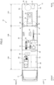
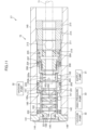
- FIG. 2 is an inside plan-view illustrating the inside of a cargo box of the vehicle.
- the vehicle 10 has a DC generator 17 and an AC generator 18 arranged side by side in the left and right sides of the electric generation area 12A.
- the DC generator 17 and the AC generator 18 are enclosed by surrounding walls 20 in the front-rear and left-right directions.
- an exhaust portion 21 (refer to FIG. 3 ) described below is provided over the DC generator 17 and the AC generator 18, so that the exhaust portion 21 and the surrounding walls 20 form a space for enclosing the electric generation area 12A during a vehicle travel or the like.
- the surrounding walls 20 provided in the left and right sides are opened or closed as a wing body type to allow the inside of the electric generation area 12A to be opened to the outside and expose the generators 17 and 18 to the outside.
- the AC generator 18 is mounted with an engine separate from the engine 13 of FIG. 1 to generate AC power using the power of the engine.
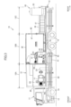
- FIG. 3 is a left side inside-view illustrating the inside of the cargo box of the vehicle in the center position of the left-right direction.
- the DC generator 17 generates electricity using the power of the engine 13. Specifically, as illustrated in FIG. 3 , a propeller shaft 22 is rotated by driving the engine 13, and this rotation allows an input shaft of the DC generator 17 to rotate through a gear box 23 to generate DC power.
- a propeller shaft 22 is rotated by driving the engine 13, and this rotation allows an input shaft of the DC generator 17 to rotate through a gear box 23 to generate DC power.
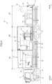
- FIG. 4 is a left side inside-view illustrating the inside of the cargo box of the vehicle, seen from the left side of the vehicle.
- the vehicle 10 has a treatment room 25 which is an enclosed space in the plasma treatment area 12B.
- the vehicle 10 further has a water plasma generator 27 and an exhaust gas disposer 28 arranged side by side in the front and rear sides of the treatment room 25.
- the water plasma generator 27 is supplied with DC power from the DC generator 17 (not shown in FIG. 4 ) to generate DC arcs (arc discharge). By virtue of the DC arcs, the water supplied to the water plasma generator 27 is dissociated or ionized to inject a water plasma jet stream having high energy.
- the water plasma generator 27 will be described below in more details.
- Hazardous wastes are provided to the water plasma jet stream injected from the water plasma generator 27 through a supply device described below.
- the water plasma jet stream is converted into a high-speed fluid having a significantly high temperature, so that hazardous substances of the hazardous wastes provided to this fluid are instantly decomposed to plasma and are then gasified.
- the exhaust gas disposer 28 is provided in a downstream side of the water plasma injection from the water plasma generator 27, that is, in front of the water plasma generator 27.
- the exhaust gas disposer 28 performs treatment for molecules gasified by the water plasma, so that the oxidized gas is neutralized using strong alkaline water, and unharmful gases are discharged to the overlying exhaust portion 21 (not shown in FIG. 2 ).
- the exhaust portion 21 has a plurality of fans to discharge gases from the front side of the electric generation area 12A by using the upper part of the electric generation area 12A as an exhaust channel.
- the exhaust gas disposer 28 will be described below in more details.
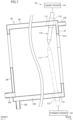
- FIG. 5 is an inside plan-view illustrating the inside of a treatment room of the vehicle in the center position of the up-down direction.
- a supply pump 31 (not shown in FIG. 5 ) and a vacuum pump 32 (not shown in FIG. 2 ) are provided vertically in parallel in positions close to the front side of the treatment room 25.
- the supply pump 31 of the upper stage supplies a coolant and plasma water to the water plasma generator 27, and the plasma water is further fed by the high-pressure pump 33 (not shown in FIG. 5 ) as high-pressure water.
- the vacuum pump 32 sucks the coolant and the plasma water from the water plasma generator 27 to discharge the coolant and the plasma water.
- the vacuum pump 32 Since the vacuum pump 32 sucks a mixture of water and air, the mixture of water and air is fed to a gas-liquid separator 35 and is separated.
- Each of the pumps 31 to 33 and the gas-liquid separator 35 are driven by AC power supplied from the AC generator 18.
- a passage of a pipe (not shown) for coupling each of the pumps 31 to 33 and the water plasma generator 27 is provided with a surge tank 37 as illustrated in FIGS. 2 and 4 .
- a change of the water pressure (fluctuation) caused by each of the pumps 31 to 33 is suppressed by such a surge tank 37, so that the coolant and the plasma water can be supplied to and discharged from the water plasma generator 27 at a stable water pressure.
- the coolant and the plasma water of the water plasma generator 27 are stored in the reservoir 40 illustrated in FIGS. 3 and 5 and are circulated and used by each of the pumps 31 to 33. Note that the same water is used as the coolant and the plasma water except that the water pressure is different when it is supplied to the water plasma generator 27.
- a double flooring structure is provided on a floor of a rear half of the treatment room 25, and the reservoir 40 is installed in the space formed by such a double flooring structure.
- the reservoir 40 has a total of eight cells including two cells in the front-rear direction by four cells in the left-right direction, and the water flows through each cell of the reservoir 40 in a meandering manner as indicated by the arrow of FIG. 5 .
- Each cell of the reservoir 40 is coupled using a pipe or the like.
- the water flowing through all of cells of the reservoir 40 flows to a tank 42 through a radiator 41 placed below the cargo box 12 and in front of the rear wheels 15. In such a flow of the water, the water heated by the water plasma generator 27 is cooled, and is supplied to the water plasma generator 27 again through the supply pump 31.
- each of left and right entrance gates 47 is provided in a rear wall body of the treatment room 25, and doors 48 are provided to open or close the entrance gates 47. Therefore, an operator can access the treatment room 25 and the space of the cargo box 12 in the rear side of the treatment room 25 through the entrance gates 47.
- the vehicle 10 further has a supply device 50 provided on the cargo box 12 in an opened space of the work area 12C.
- the supply device 50 includes a compressor 51, an air tank 52 that stores the air compressed by the compressor 51, a powder feeder 53 that feeds hazardous wastes powdered by the compressed air of the air tank 52, and a liquid feeder 54 that feeds liquid hazardous wastes using the compressed air of the air tank 52.
- the supply device 50 further has nozzles 110 and 111 (refer to FIG. 7 ) described below in the treatment room 25. The nozzles 110 and 111 are used to provide hazardous wastes fed from the powder feeder 53 and the liquid feeder 54 into the water plasma injected from the water plasma generator 27 through a pipe (not shown).
- left and right side gate boards 56 are provided on the left and right sides, respectively, of the cargo box 12.
- the side gate board 56 is hinged to the cargo box 12 in the lower end portion to rotate between an upright position and a horizontal position. In the horizontal position, the side gate board 56 is coplanar with the cargo box 12 and forms a work space as a floor surface along with the cargo box 12 in the work area 12C.
- a ladder portion 57 (not shown in FIG. 4 ) is provided on the inner surface of each side gate board 56, and a front end of each ladder portion 57 is rotatably connected to a front end of the side gate board 56. Therefore, by rotating the side gate board 56 to the ground from the horizontal position such that the rear end of the ladder portion 57 is placed in the front side, an operator is allowed to easily move between the cargo box 12 and the ground by stepping on the ladder portion 57.
- FIG. 6 is a partially cut-away view illustrating the decomposition processor according to an embodiment of the invention.
- the water plasma generator 27 is supported by a stand 70 at a predetermined height position.
- the water plasma generator 27 includes a negative electrode 71 extending in the front-rear direction, a chamber 72 into which a front end side of the negative electrode 71 is inserted, a disk-shaped positive electrode 73 formed of iron and placed obliquely downward in front of the chamber 72, and a positive electrode support 75 that supports the positive electrode 73.
- the negative electrode 71 is a round bar formed of carbon and is displaced by a feed screw shaft mechanism 76 in the front-rear direction to adjust an insertion length to the chamber 72.
- the chamber 72 is supported by a support plate 78 overlying the positive electrode support 75.
- An extension cylinder 79 extending in the front-rear direction is coupled to the rear end of the positive electrode support 75, and a motor 80 is provided in the rear end of the extension cylinder 79. A driving force of the motor 80 is transmitted to the positive electrode 73 through the extension cylinder 79 and the positive electrode support 75 to rotate the positive electrode 73.
- the chamber 72 is supplied with the coolant through the supply pump 31 and is supplied with the plasma water through the high-pressure pump 33. A part of the plasma water is injected from the front end side of the chamber 72 as water plasma. The coolant supplied to the chamber 72 and the plasma water not injected are sucked by the vacuum pump 32. Similarly, the positive electrode support 75 is supplied with the coolant flowing through the inside of the positive electrode 73 by the supply pump 31, and the coolant absorbing the heat of the positive electrode 73 is sucked by the vacuum pump 32.
- the exhaust gas disposer 28 includes a box-shaped casing 83 and a reservoir 84 provided under the casing 83 to store strong alkaline water by opening its upper part.
- the exhaust gas disposer 28 has a treatment space 85 for disposing gasified wastes over the reservoir 84 inside the casing 83.
- the exhaust gas disposer 28 further includes a shower device 87 and a panel body 88 provided inside the treatment space 85.
- the reservoir 84 internally has a water intake 90, and the strong alkaline water of the reservoir 84 is supplied from the water intake 90 to the shower device 87 by operating the pump 91 (not shown) (refer to FIG. 2 ).
- the shower device 87 neutralizes the gasified acidic gas by injecting the supplied strong alkaline water to the treatment space 85.
- the neutralized molecules are discharged to the outside through the exhaust portion 21.
- the strong alkaline water of the reservoir 84 is also pumped up from the water intake 90 to the supply port 92 over the panel body 88, and the pumped strong alkaline water flows down to the reservoir 84 along the entire rear surface of the panel body 88.
- Such a flow of the strong alkaline water neutralizes the acidic gas as described above and absorbs the heat generated from the water plasma. Therefore, it is possible to obtain a cooling effect on the entire exhaust gas disposer 28.
- the exhaust gas disposer 28 and the water plasma generator 27 are placed far from the wall body 93.
- the wall body 93 blocks the treatment space 85 of the exhaust gas disposer 28 from the rear side and partitions the inside of the treatment space 85 from the other space where the water plasma generator 27 is provided, so that air-tightness is maintained between both spaces.
- a cylindrical container 95 is penetratingly installed in the wall body 93, and the container 95 houses a front end side serving as an injection port side of the chamber 72 described below and the positive electrode 73.
- the water plasma jet stream injected from the water plasma generator 27 is covered by the container 95.
- a portion of the container 95 penetrating through the wall body 93 is entirely welded, and the container 95 is held by the wall body 93, so that the air-tightness is maintained between the container 95 and the wall body 93.
- the container 95 includes a cylinder body 96 formed in a cylindrical shape, a rear opening formation portion 97 provided in one end side (water plasma generator 27 side) of the cylinder body 96, and a front opening formation portion 98 provided in the other end side (exhaust gas disposer 28 side) of the cylinder body 96.
- An axial direction of the cylinder body 96 is slanted such that the exhaust gas disposer 28 side becomes lower than the water plasma generator 27 side.
- FIG. 7 is a cross-sectional side view illustrating the container.
- the cylinder body 96, the rear opening formation portion 97, and the front opening formation portion 98 of the container 95 have a doubled structure to form a single space 100 having a thickness within which the coolant flows.
- This space 100 communicates with a coolant supply passage 102 and a coolant discharge passage 103.
- the supply passage 102 is provided in a front lower end side of the cylinder body 96, and the discharge passage 103 is formed in an upper end side of the rear opening formation portion 97.
- the container 95 is supplied with the coolant from the supply passage 102 through a pump (not shown), and the coolant is introduced to the space 100.
- the coolant flowing through the space 100 from the supply passage 102 to the discharge passage 103 absorbs the heat generated from the water plasma. Therefore, it is possible to obtain a cooling effect of the container 95.
- FIG. 8A is a rear view illustrating the container
- FIG. 8B is a front view illustrating the container.
- an opening 97a of the rear opening formation portion 97 is formed in an opening shape matching the positive electrode 73 and the front end side of the chamber 72 to house the positive electrode 73 and the front end side of the chamber 72.
- an opening 98a of the front opening formation portion 98 is formed in an upper half of the front opening formation portion 98 and has a lower end portion extending in a horizontal direction. Therefore, as illustrated in FIG. 6 , a storage space 105 is formed in a lower corner between the front opening formation portion 98 and cylinder body 96 inside the container 95.
- the storage space 105 stores hazardous wastes not decomposed by the water plasma, and the hazardous wastes are discharged through a channel 106 penetrating through a lower part of the front opening formation portion 98.
- the first nozzle 110 of the supply device 50 (refer to FIG. 4 ) is penetratingly supported by the container 95.
- the first nozzle 110 is installed in the upper part of the container 95, and has a tip directed downward.
- the first nozzle 110 is coupled to the liquid feeder 54, and liquid-phase hazardous wastes are fed from the liquid feeder 54 to the first nozzle 110 through a pipe or the like (not shown), so that the hazardous wastes can be provided from the tip of the first nozzle 110.
- the container 95 may penetratingly support the second nozzle 111. That is, the supply device 50 may have the second nozzle 111 in addition to the first nozzle 110 to allow the first and second nozzles 110 and 111 to be selectively used.
- the second nozzle 111 is installed in the lower part of the container 95 and has a tip directed upward.
- the second nozzle 111 is coupled to the powder feeder 53, and powdered hazardous wastes are fed from the powder feeder 53 to the second nozzle 111 through a pipe or the like (not shown), so that the hazardous wastes can be provided from the tip of the second nozzle 111.
- the hazardous wastes discharged from the channel 106 through a circulation means are also provided from the first and second nozzles 110 and 111 again.
- a portion of the container 95 where each of the nozzles 110 and 111 penetrates is provided with a female thread 112, and an outer circumference of each of the nozzles 110 and 111 is provided with a male thread 113 fastenable to the female thread 112. Therefore, by fastening the male thread 113 to the female thread 112, each of the nozzles 110 and 111 is held by the container 95, and a position in the extension direction of each of the nozzles 110 and 111 can be adjusted by changing the fastening amount.
- a pair of first nozzles 110 may be provided in two places of the left and right sides of the upper part of the container 95, and a pair of second nozzles 111 may be provided in two places of the left and right sides of the lower part of the container 95.
- female threads 112 are provided in two places of the upper and lower parts of the container 95, so that each tip position of the left and right nozzles 110 and 111 is aligned and adjusted by fastening the male threads 113 to the female threads 112.
- FIG. 9 is an explanatory diagram illustrating tip positions of the first and second nozzles.
- a water plasma jet stream J is injected from an injection port 145 corresponding to a cylindrical inner circumferential surface as described below.
- the water plasma jet stream J is injected from the injection port 145 in a conical shape widened to the front side, and the center axis line position C1 of the water plasma jet stream J is aligned with the center axis line position C1 of the injection port 145 to extend in the front-rear direction.
- tip of each of the nozzles 110 and 111 is placed inside the water plasma jet stream J.
- the water plasma jet stream J becomes an area that emits light by the injection.
- the opening of the injection port 145 are arranged such that the tip of each of the nozzles 110 and 111 is positioned in a space A1 extending along the center axis line position C1 of the injection port 145.
- the tip of each of the nozzles 110 and 111 is separated from the center axis line position C1.
- the tips of the nozzles 110 and 111 may be arranged to match or overlap with the center axis line position C1.
- the tip of each of the nozzles 110 and 111 may be arranged in a space A2 extending along the center axis line position C1 of the negative electrode 71.
- hazardous wastes can be provided to a portion of the water plasma jet stream J having a higher temperature.
- FIG. 10 is a cross-sectional view illustrating internal structures of the first and second nozzles.
- the first nozzle 110 has a cooling structure 120 having a triple tube structure having first, second, and third channels 121, 122, and 123 formed sequentially from the inside to the outside.
- a basal end portion of the first nozzle 110 (upper end in FIG. 9 ) serves as a coupling portion 110a coupled to a pipe (not shown) communicating with the liquid feeder 54 (refer to FIG. 6 ).
- the coupling portion 110a communicates with the first channel 121. Therefore, the hazardous wastes fed from the liquid feeder 54 can be provided from the tip of the first nozzle 110 through the first channel 121.
- the second channel 122 and the third channel 123 communicate with each other in the tip side of the first nozzle 110 to form a single space for flowing the coolant.
- This space communicates with the coolant supply passage 125 and the discharge passage 126.
- the supply passage 125 communicates with the second channel 122
- the discharge passage 126 communicates with the third channel 123.
- the first nozzle 110 is supplied with the coolant from the supply passage 125 through a pump (not shown), and the coolant is introduced to the second channel 122.
- the coolant flowing from the basal end side of the first nozzle 110 to the tip side turns back at the tip and is introduced to the third channel 123.
- the coolant flows from the tip side of the first nozzle 110 to the basal end side and is discharged from the discharge passage 126. Using such a flow of the coolant, the heat generated from the water plasma is absorbed, and a cooling effect can be obtained across the entire length direction of the first nozzle 110.
- first and second nozzles 110 and 111 are substantially vertically opposite to each other, but have the same structure.
- the first and second nozzles 110 and 111 are coupled to different parts, that is, the liquid feeder 54 and the powder feeder 53, respectively. Therefore, the structure of the second nozzle 111 will not be described.
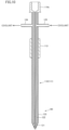
- FIG. 11 is a side view illustrating the chamber.
- FIG. 12 is a plan cross-sectional view illustrating the chamber.
- FIG. 13 is a longitudinal cross-sectional view illustrating the chamber.
- the chamber 72 of the water plasma generator 27 has a chamber body 140 that forms a cylindrical inner circumferential surface extending in the front-rear direction and a front wall portion 141 installed in the front side of the chamber body 140, so that an inner space 142 for generating water plasma is formed in the chamber 72.
- the front wall portion 141 has an opening communicating with the inner space 142, and an injection port formation plate 144 is installed to block this opening from the front side.
- the injection port formation plate 144 has an injection port 145 for injecting water plasma.
- a rib 140a extending in a circumferential direction in the vicinity of the front side is provided in the chamber body 140, and a plasma water supply passage 147 is provided in front of the rib 140a.
- a plasma water discharge passage 148 for discharging plasma water flowing to the opening is provided in the front wall portion 141. High-pressure plasma water is supplied from the high-pressure pump 33 to the plasma water supply passage 147, and the plasma water is sucked from the plasma water discharge passage 148 by virtue of the negative pressure of the vacuum pump 32.
- a coolant supply passage 150 and a coolant discharge passage 151 are provided in rear of the rib 140a of the chamber body 140.
- the coolant is supplied from the supply pump 31 to the coolant supply passage 150, and is sucked from the coolant discharge passage 151 by virtue of a negative pressure of the vacuum pump 32.
- the plasma water supply passage 147, the coolant supply passage 150, and the coolant discharge passage 151 are formed in a round hole shape corresponding to the cylindrical inner circumferential surface.
- the plasma water supply passage 147 communicates with the lower part of the inner space 142 having a circular shape as seen in a longitudinal cross-sectional view, and extends in the left-right direction. Specifically, the plasma water supply passage 147 extends in the lower tangential direction of the inner space 142. More specifically, the lower end of the plasma water supply passage 147 is positioned on a tangential line extending from the lower end of the inner space 142. As a result, the plasma water flowing from the plasma water supply passage 147 smoothly flows along a circumferential direction of the inner space 142.
- the plasma water supply passage 147 has an inner diameter d1 set to be substantially or nearly equal to a width h1 between the inner circumferential surface of the chamber body 140 that forms the inner space 142 and a cylindrical portion 162 described below.
- the longitudinal cross-sectional shape of the coolant supply passage 150 is similar to the longitudinal cross-sectional shape of the plasma water supply passage 147, so that the coolant as well as the plasma water can flow to the inner space 142.
- the coolant discharge passage 151 communicates with the upper part of the inner space 142 and extends in the left-right direction as seen in a longitudinal cross-sectional view.
- the water plasma generator 27 has a substantially cylindrical vortex water flow generator 160 housed in the chamber 72.
- the vortex water flow generator 160 is arranged such that the inner space 142 is aligned with the center axis line position C1. Note that this center axis line position C 1 is aligned with the center axis line position C1 of the injection port 145 described above (refer to FIG. 9 ). Therefore, as seen in a longitudinal cross-sectional view, the inner space 142 forms a circular space between the inner circumferential surface of the inner space 142 and the outer circumferential surface of the vortex water flow generator 160, and the plasma water flowing to the inner space 142 flows to turn in a circular space as described above.
- FIG. 14 is an exploded longitudinal cross-sectional view illustrating a part of the chamber and the vortex water flow generator.
- the vortex water flow generator 160 includes a cylindrical portion 162 that forms a cylindrical shape, first and second middle partitions 163 and 164 protruding from the inner circumference of the cylindrical portion 162, a rear partition (one-end-side partition) 165 provided in one end side (rear end side) of the cylindrical portion 162, and a front partition (the-other-end-side partition) 166 formed in the other end side (front end side) of the cylindrical portion 162.
- the first middle partition 163 is placed in rear of the second middle partition 164.
- the rear partition 165 is arranged to face the negative electrode 71 (refer to FIG. 11 ) placed in the rear side.
- a front end portion of the vortex water flow generator 160 is fitted to the opening of the front wall portion 141.
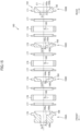
- FIG. 15 is an exploded longitudinal cross-sectional view illustrating the vortex water flow generator.
- the cylindrical portion 162 is dividable into a plurality of pieces along an axial direction (front-rear direction).
- the cylindrical portion 162 includes a front end portion 170 positioned in the injection port 145 side (front side), a rear end portion 171 positioned in the side opposite to the front end portion 170 (rear side), first and second middle portions 173 and 174, three water flow generation rings 176, and six spacer rings 177 positioned between the front and rear end portions 170 and 171.
- the spacer rings 177 are provided on both front and rear sides of each of the three water flow generation rings 176, and the inner circumference of the spacer ring 177 protrudes forward or backward and is fitted to the inner circumference of the water flow generation ring 176.
- the first and second middle portions 173 and 174 are interposed between the water flow generation rings 176 from both the front and rear sides while nipping the spacer rings 177.
- the front end portion 170 is provided in front of the frontmost water flow generation ring 176 while nipping the spacer ring 177
- the rear end portion 171 is provided in rear of the rearmost water flow generation ring 176 while nipping the spacer ring 177.
- FIG. 16 is a partially exploded perspective view illustrating the vortex water flow generator.
- the front end portion 170 is formed integrally with the outer circumference of the front partition 166 in a flange shape
- the rear end portion 171 is formed integrally with the outer circumference of the rear partition 165 in a flange shape. Therefore, the front end portion 170 and the front partition 166 constitute a head portion 160A as one component, and the rear end portion 171 and the rear partition 165 constitute a terminated portion 160B as one component.
- first middle portion 173 is formed integrally with an outer side of the first middle partition 163 in a flange shape
- second middle portion 174 is formed integrally with an outer side of the second middle partition 164 in a flange shape. Therefore, the first middle portion 173 and the first middle partition 163 constitute an annulus disk portion 160C as one component, and the second middle portion 174 and the second middle partition 164 constitute an annulus disk portion 160D as one component.
- Partitions 163 to 166 have circular openings 163a to 166a, respectively, to include the center axis line position C1 of the cylindrical portion 162. According to an embodiment of the invention, center positions of the openings 163a to 166a are aligned with the center axis line position C1. Each of the openings 163a to 166a has a different opening shape in size. Specifically, the opening 165a of the rear partition 165 has the largest diameter D1, and the opening 163a of the first middle partition 163 has the smallest diameter D2.
- the diameters have a relationship D4>D3>D2, where "D3" denotes a diameter of the opening 164a of the second middle partition 164, and “D4" denotes a diameter of the opening 166a of the front partition 166.
- D3 denotes a diameter of the opening 164a of the second middle partition 164
- D4 denotes a diameter of the opening 166a of the front partition 166.
- the rear surfaces of the partitions 163 to 166 are formed as tapered surfaces 163b to 166b, respectively, narrowed forward as close to the center positions of the openings 163a to 166a, respectively (as far from the negative electrode 71 (refer to FIG. 11 )).
- the tapered surfaces 163b, 164b, and 166b of the first middle partition 163, the second middle partition 164, and the front partition 166 are curved to form a bowl-shaped surface.
- the tapered surfaces 163b, 164b, and 166b are curved surfaces formed such that regions close to the openings 163a, 164a, and 166a are placed on a plane perpendicular to the center axis line position C1, and slopes become steep as going to the outside from the regions.
- the front surface of each of the partitions 163 to 166 is placed on a plane perpendicular to the center axis line position C1.
- arc-shaped beveled portions 163c, 164c, and 166c are formed between the openings 163a, 164a, and 166a and the tapered surfaces 163b, 164b, and 166b, respectively.
- the beveled portions 163c, 164c, and 166c have curvatures larger than curvatures of the tapered surfaces 163b, 164b, and 166b, respectively.
- each of the three water flow generation rings 176 includes a plurality of channels 180.
- three channels 180 are formed in a single water flow generation ring 176, and two channels 180 are not illustrated in FIG. 13 .
- three channels 180 are formed in three positions of the water flow generation ring 176 along the extending direction of the center axis line position C1, and front and rear positions of the three channels 180 are aligned with each other.
- three channels 180 are formed in each gap between the partitions 163 and 166 neighboring in the front and rear sides.
- Each channel 180 is formed in a round hole shape having a cylindrical inner circumferential surface.
- the channels 180 are formed at equal angular intervals along a circumferential direction of the water flow generation ring 176 (at an interval of 120° in this embodiment).
- Each channel 180 penetrates through the water flow generation ring 176 to allow the inside and the outside to communicate with each other and extends in a direction sloped from a thickness direction.
- each channel 180 extends in a tangential direction to the inner circumference of the water flow generation ring 176 in the communicating position. More specifically, each channel 180 is formed in a tangential position to the inner circumference of the water flow generation ring 176 to allow the inner circumferential surface of the channel 180 to linearly overlap.
- an angle ⁇ between a flow direction of the plasma water from the outside to the inside of the channel 180 and a flow direction of the plasma water turning at the outside of the water flow generation ring 176 becomes an acute angle.
- the channel 180 By forming the channel 180 in this manner, the plasma water flowing along the inner circumferential surface of the chamber body 140 in the outside of the cylindrical portion 162 flows to the inside of the cylindrical portion 162 through the channel 180. In addition, the plasma water flows smoothly along the inner circumferential surface of the cylindrical portion 162, so that a vortex water flow turning a circular shape is formed to provide a cavity in the center axis line position C1 as seen in a longitudinal cross-sectional view.
- the water plasma generator 27 further has various components in rear of the vortex water flow generator 160 in the chamber 72. These components will now be described sequentially from the front side to the rear side.
- a cylindrical stopper 201 makes contact with a rear surface of the rib 140a of the chamber body 140.
- the rear partition 165 and the rear end portion 171 of the vortex water flow generator 160 are fitted to the opening of the stopper 201 to hold the position of the vortex water flow generator 160 not to move backward.
- a stepped cylindrical casing 202 makes contact with the rear surface of the stopper 201, and a cylindrical water flow forming cylinder 203 is fitted to the rear surface of the casing 202.
- the water flow forming cylinder 203 has a plurality of channels 203a shaped to match the channels 180 described above.
- the coolant supplied from the coolant supply passage 150 to the inner space 142 flows to the inside of the water flow forming cylinder 203 and makes contact with the negative electrode 71 to cool the negative electrode 71.
- the coolant subjected to the cooling is discharged from the coolant discharge passage 151 (not shown in FIG. 12 ).
- the coolant supplied from the coolant supply passage 150 flows to the vortex water flow generator 160 placed in front through the stopper 201 and the like and is also used as plasma water.
- the plasma water does not hinder cooling of the negative electrode 71 through the stopper 201 and the like.
- the plasma water and the coolant mean main use purposes depending on differences in supply position and supply pressure, so that the common water is shared between the plasma water and the coolant available for both the use purposes.
- a sensor hole 203b is formed in the left side of the water flow forming cylinder 203, and a sensor 204 (not shown in FIG. 11 ) is provided to face the sensor hole 203b.
- the sensor 204 is installed in a sensor installation hole 140b (not shown in FIG. 11 ) formed in the chamber body 140.
- the sensor 204 detects presence of the negative electrode 71 placed in the front or rear side of the sensor hole 203b through the sensor hole 203b. If the sensor 204 detects that there is no negative electrode 71, the detection data is output to a controller (not shown), and the feed screw shaft mechanism 76 (refer to FIG. 6 ) is driven to move the negative electrode 71 forward by a predetermined length. As a result, a front end position of the negative electrode 71 can be maintained within a predetermined range in front of the sensor hole 203b.
- a stepped cylindrical casing 206 internally having a step is provided in rear of the water flow forming cylinder 203.
- a front end portion of the casing 206 is fitted to the rear end side of the water flow forming cylinder 203.
- a contactor 207 that makes contact with and holds the negative electrode 71 is provided inside the casing 206.
- the contactor 207 is divided into several pieces on a predetermined angle basis in a circumferential direction although not shown in the drawing.
- the inner diameter of the contactor 207 is variable.
- a ring-shaped elastic body 208 is provided on the outer circumference of the contactor 207 such that a contact state between the negative electrode 71 and the contactor 207 is maintained by tightly fastening the negative electrode 71 while interposing the contactor 207 by virtue of an elastic force of the elastic body 208.
- the ring-shaped seal holder 209 makes contact with the rear end surface of the contactor 207, and a seal 210 is provided in a seal holder 209.
- the seal 210 maintains liquid tightness with the negative electrode 71 to restrict leaking of the coolant to the rear side of the seal 210.
- the ring-shaped connector 211 makes contact with the rear end surface of the seal holder 209, and a wire 213 is connected to the connector 211 through an adapter and the like (not shown).
- the wire 213 is supplied with DC power from the DC generator 17 (refer to FIG. 2 ) through a switch board and the like.
- the connector 211, the seal holder 209, and the contactor 207 are formed of a conductive material, and the negative electrode 71 and the wire 213 are electrically connected through the connector 211, the seal holder 209, and the contactor 207. As a result, DC power for generating arc discharge is supplied to the negative electrode 71.
- the ring-shaped spacer 214 makes contact with a rear end surface of the connector 211, and a stop screw 215 penetrating through the negative electrode 71 makes contact with a rear end surface of the spacer 214.
- a female thread (not shown) fastenable to the stop screw 215 is formed on the inner circumferential surface in rear of the chamber body 140.
- the components 221 to 225 of the chamber 72 are seal members such as an O-ring for maintaining liquid tightness on such a contact surface.
- the plasma water flows to turn in a cylindrical space provided between the inner circumferential surface of the chamber body 140 that forms the inner space 142 and the outer circumferential surface of the vortex water flow generator 160.
- the plasma water flows to the inside of the cylindrical portion 162 through the channel 180.
- the inner circumferential surface of the channel 180 linearly overlaps with a tangential position on the inner circumference of the water flow generation ring 176. Therefore, the plasma water flows smoothly along the inner circumferential surface of the cylindrical portion 162.
- FIG. 17 is a diagram for describing a vortex water flow by enlarging some parts of FIG. 11 .
- the plasma water flowing from the channels 180 to the inside of the cylindrical portion 162 flows to turn between the partitions 163 to 165 neighboring in the front-rear direction.
- the turning plasma water is sucked from the plasma water discharge passage 148 provided in the front wall portion 141.
- the plasma water flows to the front side through the openings 163a, 164a, and 166a, passes through a gap between the front end of the front partition 166 and the injection port formation plate 144, and is discharged from the plasma water discharge passage 148.
- the turning vortex water flow W is formed to provide a cavity H in the center axis line position C1.
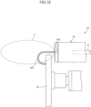
- the cavity H is not provided in the vortex water flow W, no arc discharge AR (refer to FIG. 18 ) is generated between the positive electrode 73 and the negative electrode 71. Therefore, it is important to form the vortex water flow W to stably generate the cavity H.
- the inventors made experiments over and over under various conditions and found a fact that the cavity H of the vortex water flow W is most stably provided when a relationship D4>D3>D2 is established between the diameters D2 to D4 of the openings 163a, 164a, and 166a as illustrated in FIGS. 14 and 16 . It is conceived that, since the opening diameters D2 to D4 increase toward the front side in a conical shaped space, the plasma water easily flows from the rear side to the front side as close to the downstream side (close to the front side). Note that, besides the aforementioned relationship, the cavity H is stably provided by forming the opening diameters D1 to D4 in different sizes.
- At least one of the openings 163a to 166a may have a different size of the diameter from the other opening diameters.
- the openings 163a, 164a, and 166a in different sizes, it is possible to improve freedom of adjustment for the amount of plasma water flowing through each of the opening 163a, 164a, and 166a.
- the tapered surfaces 163b, 164b, and 166b By curving the tapered surfaces 163b, 164b, and 166b to form a bowl-shaped surface or forming the arc-shaped beveled portions 163c, 164c, and 166c, it is possible to suppress a turbulence that hinders formation of the vortex water flow W. This contributes to stable formation of the cavity H. Note that the plasma water also has an effect of cooling the vortex water flow generator 160 or the chamber body 140 by virtue of the turning flow.
- arc discharge AR is generated between the positive electrode 73 and the negative electrode 71.
- the arc discharge AR is generated through the cavity H of the vortex water flow W.
- the plasma water of the vortex water flow W is dissociated or ionized, and a water plasma jet stream J having high energy is injected from the injection port 145.
- the water plasma jet stream J is converted into a high-speed fluid having a significantly high temperature, and the hazardous wastes provided from the tip of each of the nozzles 110 and 111 are decomposed as illustrated in FIG. 9 . Since the tip of each of the nozzles 110 and 111 is arranged in the positions described in conjunction with FIG. 9 according to an embodiment of the invention, the decomposition can be performed under the better condition in a part having a higher temperature in the water plasma jet stream J. Therefore, it is possible to efficiently decompose the provided hazardous wastes into gasified wastes.
- the hazardous wastes may include PCB, sulfuric acid pitches, asbestos, freon, halon, tires, various types of garbage, and the like. As illustrated in FIG.
- liquid wastes are provided through the liquid feeder 54, and granulated or powdered wastes are provided through the powder feeder 53. Even when such hazardous wastes are provided, it is possible to decompose the hazardous wastes into unharmful wastes.
- the container 95 is heated during the decomposition of hazardous wastes.
- the container 95 can be cooled and used by passing the coolant within a thickness of the container 95.
- the nozzles 110 and 111 since each of the nozzles 110 and 111, especially their tips are positioned in the middle of the water plasma jet stream J, the nozzles 110 and 111 are heated with high energy.
- using the cooling structure 120 described above in conjunction with FIG. 10 it is possible to suppress damage that may be caused by the heating.
- the acidic gas gasified by the water plasma jet stream J is neutralized by the exhaust gas disposer 28 described above in conjunction with FIG. 6 . Therefore, it is possible to convert the gas treated by the water plasma into the safer exhaust gas. In addition, the unharmful gas can be discharged from the exhaust portion 21 placed in the upper part.
- the hazardous wastes described above can be disposed on the vehicle 10. Therefore, it is possible to operate the water plasma generator 27 in a mobile manner and dispose hazardous wastes unsuitable for delivery in a field where the wastes are stored. As a result, it is possible to reduce cost for moving and disposing hazardous wastes and to dispose a large amount of hazardous wastes to reduce cost for disposal.
- the water plasma jet stream is discharged from the water plasma burner, and the water plasma jet stream is discharged in a shape widening from the injection port of the water plasma burner as far from the injection port within a predetermined range.
- a supply means for supplying incinerated ashes from the upper side of the water plasma jet stream is provided far from the injection port of the water plasma burner by a predetermined distance.
- a tip (lower end) of the supply means serving as a supply port is arranged over the water plasma jet stream.
- a temperature of the water plasma jet stream decreases as far from the injection port, and decomposition performance for incinerated ashes also decreases. Therefore, there is a demand for improvement of the decomposition performance.
- the supply device 50 has the nozzles 110 and 111 for providing hazardous wastes (decomposition target object) from the tip, and the tips of the nozzles 110 and 111 are placed inside of the water plasma jet stream.
- the middle partition includes a pair of the first and second middle partitions 163 and 164 in the aforementioned embodiments
- the number of middle partitions may be three or more, or singular as long as the vortex water flow W can be formed as described above.
- the vortex water flow generator 160 can be divided into a plurality of members as illustrated in FIG. 15 , the members neighboring in the front-rear direction may be integrated without a limitation.
- the spacer ring 177 and the water flow generation ring 176 placed in the rear may be integrated with each other.
- various structures may also be employed as long as they can be formed.
- the shapes of the openings 163a to 166a are not limited to a circular shape.
- the shape of the opening may be changed to an oval shape, a polygonal shape, and the like as long as the vortex water flow W can be generated as described above.
- the position of the channel 180 in the circumferential direction of the water flow generation ring 176 is not particularly limited. Although the positions of the channels 180 are aligned across all of the water flow generation rings 176 in FIG. 15 , the position of the channel 180 may be changed in each water flow generation ring 176.
- each nozzle 110 or 111 may also be changed as long as the nozzles 110 and 111 are placed in the tip positions described in the aforementioned embodiments.
- the target object decomposed and disposed by the water plasma generator 27 is not limited to the aforementioned hazardous wastes.
- An unharmful object may also be used as a decomposition target object.
- the water plasma generator 27 may be used in any process based on water plasma such as a thermal spray without limiting to the waste disposal.
Landscapes
- Chemical & Material Sciences (AREA)
- Chemical Kinetics & Catalysis (AREA)
- Organic Chemistry (AREA)
- Engineering & Computer Science (AREA)
- Plasma & Fusion (AREA)
- Physics & Mathematics (AREA)
- Health & Medical Sciences (AREA)
- General Health & Medical Sciences (AREA)
- Toxicology (AREA)
- Spectroscopy & Molecular Physics (AREA)
- Environmental & Geological Engineering (AREA)
- Emergency Management (AREA)
- Business, Economics & Management (AREA)
- General Chemical & Material Sciences (AREA)
- Analytical Chemistry (AREA)
- Plasma Technology (AREA)
- Physical Or Chemical Processes And Apparatus (AREA)
Claims (18)
- Générateur de flux d'eau tourbillonnaire (160) placé entre une électrode négative (71) et une électrode positive (73) d'un générateur de plasma d'eau (27) qui injecte un plasma d'eau, le plasma d'eau devenant un courant-jet par dissociation ou ionisation d'eau pour former un flux d'eau tourbillonnaire ayant une cavité pour faire passer une décharge d'arc générée entre les électrodes négative et positive, le générateur de flux d'eau tourbillonnaire (160) comprenant :une portion cylindrique (162) configurée pour former le flux d'eau tourbillonnaire le long d'une circonférence intérieure ;au moins une cloison médiane (163, 164) faisant saillie à partir de la circonférence intérieure de la portion cylindrique (162) ;une cloison de côté une extrémité (165) disposée dans le côté une extrémité de la portion cylindrique (162) pour faire face à l'électrode négative (71) ; etune cloison de côté autre extrémité (166) disposée dans le côté autre extrémité de la portion cylindrique (162),dans lequel chacune des cloisons (163, 164, 165, 166) présente une ouverture (163a, 164a, 165a, 166a) dans une position incluant une ligne d'axe central de la portion cylindrique (162), les ouvertures ayant des formes d'ouverture différentes en termes de taille,l'au moins une cloison médiane (163, 164) et la cloison de côté autre extrémité (166) présentent des surfaces au niveau du côté électrode négative, les surfaces étant formées par des surfaces coniques (163b, 164b, 166b) s'éloignant progressivement de l'électrode négative (71) en se rapprochant de la ligne d'axe central,une portion biseautée en forme d'arc (163c, 164c, 166c) est formée entre la surface conique (163b, 164b, 166b) et une surface circonférentielle intérieure de l'ouverture (163a, 164a, 166a), respectivement, etla portion cylindrique (162) présente un canal (180) pour le passage de l'eau de l'extérieur vers l'intérieur de celle-ci.
- Générateur de flux d'eau tourbillonnaire (160) selon la revendication 1, dans lequel des formes des ouvertures de l'au moins une cloison médiane (163, 164) et de la cloison de côté autre extrémité (166) augmentent progressivement en taille dans un ordre en éloignement de l'électrode négative (71).
- Générateur de flux d'eau tourbillonnaire (160) selon la revendication 1 ou 2, dans lequel une pluralité de cloisons médianes (163, 164) sont prévues.
- Générateur de flux d'eau tourbillonnaire (160) selon la revendication 1 ou 2, dans lequel la surface conique (163b, 164b, 166b) est courbée pour être évidée le long d'une surface en forme de bol.
- Générateur de flux d'eau tourbillonnaire (160) selon la revendication 1 ou 2, dans lequel chacun du canal (180) et de la portion cylindrique (162) présente une surface circonférentielle intérieure cylindrique, et
la surface circonférentielle intérieure du canal (180) chevauche linéairement une position tangentielle de la portion cylindrique (162). - Générateur de flux d'eau tourbillonnaire (160) selon la revendication 5, dans lequel le canal (180) est formé entre les cloisons (163, 166) voisines.
- Générateur de flux d'eau tourbillonnaire (160) selon la revendication 5, dans lequel une pluralité de canaux (180) sont formés le long d'une direction circonférentielle de la portion cylindrique (162) pour être dans une position identique dans une direction d'extension de la ligne d'axe central.
- Générateur de flux d'eau tourbillonnaire (160) selon la revendication 1 ou 2, dans lequel chacune des cloisons est installée de manière détachable dans la portion cylindrique (162).
- Générateur de plasma d'eau (27) comprenant :le générateur de flux d'eau tourbillonnaire (160) selon la revendication 1 ou 2 ;une chambre (72) configurée pour loger le générateur de flux d'eau tourbillonnaire (160) ; etune électrode positive (73) et une électrode négative (71) configurées pour générer une décharge d'arc,dans lequel le générateur de flux d'eau tourbillonnaire (160) est placé entre l'électrode négative (71) et l'électrode positive (73) pour former un flux d'eau tourbillonnaire à travers lequel passe une décharge d'arc générée entre les électrodes négative et positive.
- Processeur de décomposition (60) comprenant :le générateur de plasma d'eau (27) selon la revendication 9 ; etun dispositif d'alimentation (50) configuré pour alimenter en objet cible de décomposition un plasma d'eau injecté à partir du générateur de plasma d'eau (27),dans lequel l'objet cible de décomposition est décomposé par le plasma d'eau.
- Processeur de décomposition (60) selon la revendication 10, dans lequel le dispositif d'alimentation (50) présente une buse (110, 111) pour fournir l'objet cible de décomposition à partir d'une pointe, et
la pointe de la buse (110, 111) est placée à l'intérieur du courant-jet de plasma d'eau. - Processeur de décomposition (60) selon la revendication 11, dans lequel la pointe de la buse (110, 111) est placée dans un espace (A1) formé par l'extension de l'ouverture de l'orifice d'injection le long de la ligne d'axe central.
- Processeur de décomposition selon la revendication 11, dans lequel la pointe de la buse (110, 111) est placée dans un espace (A2) formé par l'extension de l'électrode négative (71) le long de la ligne d'axe central.
- Processeur de décomposition (60) selon la revendication 11, dans lequel la pointe de la buse (110, 111) est placée pour correspondre avec ou chevaucher une position de ligne d'axe central de l'orifice d'injection (145).
- Processeur de décomposition (60) selon la revendication 11, dans lequel la buse (110, 111) présente une structure de refroidissement (120) qui fait circuler un liquide de refroidissement à l'intérieur de la pointe, et
la structure de refroidissement (120) inclut :un premier canal (121) à travers lequel passe l'objet cible de décomposition ;un deuxième canal (122) prévu dans un côté extérieur du premier canal (121) pour faire passer le liquide de refroidissement d'un côté extrémité de base de la buse au côté pointe ; etun troisième canal (123) prévu sur un côté extérieur du deuxième canal (122) pour communiquer avec le deuxième canal (122) dans le côté pointe et faire passer le liquide de refroidissement du côté pointe au côté extrémité de base. - Processeur de décomposition (60) selon la revendication 11, comprenant en outre :un éliminateur de gaz d'échappement (28) présentant un espace de traitement (85) pour éliminer un gaz généré par la décomposition de l'objet cible de décomposition ;un corps de paroi (93) qui cloisonne l'intérieur et l'extérieur de l'espace de traitement (85) ; etun récipient cylindrique (95) configuré pour loger l'électrode positive (73) et l'orifice d'injection pour décharger le gaz dans l'espace de traitement (85),dans lequel la buse (110, 111) est supportée par le récipient (95), etle récipient (95) présente une épaisseur au sein de laquelle est formé un espace pour la circulation du liquide de refroidissement.
- Véhicule doté d'un processeur de décomposition comprenant le processeur de décomposition (60) selon la revendication 10, dans lequel le processeur de décomposition (60) est monté sur une boîte de chargement d'un camion.
- Procédé de décomposition comprenant :l'alimentation en objet cible de décomposition du plasma d'eau injecté à partir du générateur de plasma d'eau (27) selon la revendication 9 ; etla décomposition de l'objet cible de décomposition.
Applications Claiming Priority (3)
| Application Number | Priority Date | Filing Date | Title |
|---|---|---|---|
| JP2016000527 | 2016-01-05 | ||
| JP2016000519A JP6035438B1 (ja) | 2016-01-05 | 2016-01-05 | 渦水流発生器、水プラズマ発生装置、分解処理装置、分解処理装置搭載車両及び分解処理方法 |
| PCT/JP2016/088498 WO2017119326A1 (fr) | 2016-01-05 | 2016-12-22 | Générateur d'écoulement d'eau tourbillonnaire, dispositif de génération de plasma d'eau, dispositif de traitement de décomposition, véhicule comprenant un dispositif de traitement de décomposition, et procédé de traitement de décomposition |
Publications (4)
| Publication Number | Publication Date |
|---|---|
| EP3401007A1 EP3401007A1 (fr) | 2018-11-14 |
| EP3401007A4 EP3401007A4 (fr) | 2019-09-04 |
| EP3401007B1 true EP3401007B1 (fr) | 2025-02-05 |
| EP3401007C0 EP3401007C0 (fr) | 2025-02-05 |
Family
ID=59273612
Family Applications (1)
| Application Number | Title | Priority Date | Filing Date |
|---|---|---|---|
| EP16883825.8A Active EP3401007B1 (fr) | 2016-01-05 | 2016-12-22 | Générateur d'écoulement d'eau tourbillonnaire, dispositif de génération de plasma d'eau, dispositif de traitement de décomposition, véhicule comprenant un dispositif de traitement de décomposition, et procédé de traitement de décomposition |
Country Status (6)
| Country | Link |
|---|---|
| US (3) | US11065491B2 (fr) |
| EP (1) | EP3401007B1 (fr) |
| CN (3) | CN111921472A (fr) |
| AU (3) | AU2016384478B2 (fr) |
| ES (1) | ES3013872T3 (fr) |
| WO (1) | WO2017119326A1 (fr) |
Families Citing this family (6)
| Publication number | Priority date | Publication date | Assignee | Title |
|---|---|---|---|---|
| AU2016384478B2 (en) * | 2016-01-05 | 2020-10-01 | Helix Co., Ltd. | Vortex water flow generator, water plasma generating device, decomposition treatment device, vehicle equipped with decomposition treatment device, and decomposition treatment method |
| CN107949139A (zh) * | 2017-11-29 | 2018-04-20 | 中国航天空气动力技术研究院 | 一种串连式电弧等离子体发生器 |
| JP7171082B2 (ja) * | 2018-11-08 | 2022-11-15 | 株式会社Helix | 分解処理装置 |
| CN112841546B (zh) * | 2021-03-08 | 2023-05-09 | 河南禾胜合食品有限公司 | 一种利用湍流等离子体活化水泡发毛肚、黄喉的方法 |
| JP7606249B1 (ja) | 2023-11-08 | 2024-12-25 | 株式会社Helix | 分解処理装置 |
| JP2025176362A (ja) * | 2024-05-21 | 2025-12-04 | 株式会社Helix | 加熱装置 |
Family Cites Families (53)
| Publication number | Priority date | Publication date | Assignee | Title |
|---|---|---|---|---|
| DE1571153A1 (de) * | 1962-08-25 | 1970-08-13 | Siemens Ag | Plasmaspritzpistole |
| CH525705A (de) * | 1968-12-24 | 1972-07-31 | Lonza Ag | Verwendung von vortex-stabilisierten Plasmabrennern zur Durchführung von chemischen Reaktionen |
| JPS56152198A (en) | 1980-04-21 | 1981-11-25 | Vysoka Skola Chem Tech | Method and device for radially stabilizing and equalizing plasma stream |
| SE448509B (sv) | 1982-02-15 | 1987-02-23 | Ceskoslovenska Akademie Ved | Forfarande for stabilisering av lagtemperaturplasma i en ljusbagsbrennare samt vetskestabiliserad plasmabrennare |
| CS232677B1 (cs) | 1982-02-15 | 1985-02-14 | Karel Zverina | Způsob výroby nízkoteplotního plasmatu |
| JPH0763033B2 (ja) | 1984-06-27 | 1995-07-05 | 吉明 荒田 | 大出力プラズマジェット発生装置 |
| JPS6358799A (ja) | 1986-08-28 | 1988-03-14 | 日本高周波株式会社 | 反応試料噴出部をプラズマ・フレ−ム中に挿入した高周波プラズマ反応装置 |
| JPH0693396B2 (ja) * | 1987-11-27 | 1994-11-16 | 日本高周波株式会社 | 高周波プラズマ反応装置の点火方法 |
| JP2510091B2 (ja) * | 1987-12-04 | 1996-06-26 | 日鐵溶接工業 株式会社 | プラズマジェットト―チ |
| IN180745B (fr) * | 1990-01-17 | 1998-03-14 | Univ Sydney | |
| US5013883A (en) * | 1990-05-18 | 1991-05-07 | The Perkin-Elmer Corporation | Plasma spray device with external powder feed |
| US5319176A (en) * | 1991-01-24 | 1994-06-07 | Ritchie G. Studer | Plasma arc decomposition of hazardous wastes into vitrified solids and non-hazardous gasses |
| NO174180C (no) * | 1991-12-12 | 1994-03-23 | Kvaerner Eng | Innföringsrör for brenner for kjemiske prosesser |
| US5346133A (en) * | 1993-03-25 | 1994-09-13 | The M. W. Kellogg Company | High temperature liquid injection apparatus |
| JP3253175B2 (ja) * | 1993-06-02 | 2002-02-04 | 月島機械株式会社 | 球状銀微粒子の製造方法 |
| JP3028709B2 (ja) * | 1993-07-21 | 2000-04-04 | 富士電機株式会社 | プラズマ溶射装置 |
| KR100370184B1 (ko) * | 1993-10-14 | 2003-10-17 | 아토믹 에너지 코퍼레이션 오브 사우스 아프리카 리미티드 | 플루오르카본화합물제조방법 |
| US5747767A (en) * | 1995-09-13 | 1998-05-05 | The Esab Group, Inc. | Extended water-injection nozzle assembly with improved centering |
| JP3333699B2 (ja) * | 1996-11-22 | 2002-10-15 | 仲道 山崎 | 連続水熱反応における原料粒子噴霧方法および装置 |
| IL136431A (en) * | 2000-05-29 | 2005-09-25 | E E R Env Energy Resrc Israel | Apparatus for processing waste |
| JP3408779B2 (ja) | 2000-05-31 | 2003-05-19 | 三菱重工業株式会社 | 焼却灰減容と成形化方法及び焼却灰減容と成形化システム |
| JP2003024902A (ja) | 2001-07-18 | 2003-01-28 | Mitsubishi Heavy Ind Ltd | 廃棄物処理装置 |
| JP3714924B2 (ja) * | 2002-07-11 | 2005-11-09 | 東京エレクトロン株式会社 | プラズマ処理装置 |
| SG111177A1 (en) * | 2004-02-28 | 2005-05-30 | Wira Kurnia | Fine particle powder production |
| JP2006002242A (ja) * | 2004-06-21 | 2006-01-05 | Ofic Co | プラズマ溶射装置 |
| KR101380793B1 (ko) * | 2005-12-21 | 2014-04-04 | 슐저메트코(유에스)아이엔씨 | 하이브리드 플라즈마-콜드 스프레이 방법 및 장치 |
| JP4432086B2 (ja) * | 2006-11-28 | 2010-03-17 | 勇吉 矢口 | 車載式水プラズマ有害廃棄物処理装置 |
| CN101983087B (zh) * | 2008-02-08 | 2013-04-17 | Peat国际公司 | 处理废物的方法和设备 |
| CN101468788B (zh) * | 2008-04-25 | 2010-10-27 | 周开根 | 垃圾、生物质原料生产合成气的系统及设备 |
| JP2009272565A (ja) * | 2008-05-09 | 2009-11-19 | Toshiba Corp | 半導体記憶装置、及びその製造方法 |
| CN201454523U (zh) * | 2009-03-20 | 2010-05-12 | 清华大学 | 一种应用于等离子体煤裂解制乙炔反应器的煤粉喷射装置 |
| EP2236211B1 (fr) * | 2009-03-31 | 2015-09-09 | Ford-Werke GmbH | Système pour la déposition thermique de revêtements par pulvérisation à arc électrique |
| WO2010127344A2 (fr) * | 2009-05-01 | 2010-11-04 | The Regents Of The University Of Michigan | Système hybride plasma/laser in situ |
| CN201596843U (zh) * | 2010-02-04 | 2010-10-06 | 牛世安 | 水压缩等离子弧切割枪 |
| WO2012031338A1 (fr) * | 2010-09-08 | 2012-03-15 | Ecoplasma B.V.B.A. | Procédé et appareil de production d'un combustible |
| CN102478242A (zh) * | 2010-11-25 | 2012-05-30 | 王守国 | 三喷头等离子体医疗垃圾焚烧系统 |
| WO2012115533A1 (fr) * | 2011-02-25 | 2012-08-30 | Nippon Steel Corporation, | Torche à plasma |
| CA2753043A1 (fr) * | 2011-03-18 | 2012-09-18 | Pyrogenesis Canada Inc. | Hydrolyse par arc de plasma de vapeur de substances appauvrissant l'ozone |
| US20130162136A1 (en) * | 2011-10-18 | 2013-06-27 | David A. Baldwin | Arc devices and moving arc couples |
| US9150949B2 (en) | 2012-03-08 | 2015-10-06 | Vladmir E. BELASHCHENKO | Plasma systems and methods including high enthalpy and high stability plasmas |
| FR2998440B1 (fr) * | 2012-11-19 | 2022-03-11 | Abenz 81 40 | Procede et dispositif de traitement de matiere fragmentee par flux de plasma reactif a pression atmospherique |
| DE102013200062A1 (de) * | 2013-01-04 | 2014-07-10 | Ford-Werke Gmbh | Vorrichtung zum thermischen Beschichten einer Oberfläche |
| CN103104575A (zh) * | 2013-01-21 | 2013-05-15 | 南京航空航天大学 | 电弧式放电等离子体涡流发生器 |
| CN103896361B (zh) * | 2014-03-22 | 2015-07-01 | 中国科学院等离子体物理研究所 | 水等离子体炬处理有机废水装置与方法 |
| JP5799153B1 (ja) * | 2014-10-23 | 2015-10-21 | 株式会社金星 | プラズマトーチ、プラズマ溶射装置、およびプラズマトーチの制御方法 |
| CN204509225U (zh) * | 2015-01-19 | 2015-07-29 | 清华大学 | 水煤浆雾化喷嘴和具有水煤浆雾化喷嘴的气化炉 |
| CN205258204U (zh) * | 2015-09-21 | 2016-05-25 | 深圳市同盛绿色科技有限公司 | 水处理装置 |
| AU2016384478B2 (en) * | 2016-01-05 | 2020-10-01 | Helix Co., Ltd. | Vortex water flow generator, water plasma generating device, decomposition treatment device, vehicle equipped with decomposition treatment device, and decomposition treatment method |
| DE102016014362A1 (de) * | 2016-12-02 | 2018-06-07 | CCP Technology GmbH | Plasmareaktor und Verfahren zum Betrieb eines Plasmareaktors |
| CN107525071B (zh) * | 2017-08-03 | 2019-07-05 | 华中科技大学 | 一种加水等离子体燃烧系统 |
| CN107949139A (zh) * | 2017-11-29 | 2018-04-20 | 中国航天空气动力技术研究院 | 一种串连式电弧等离子体发生器 |
| CN108770172B (zh) * | 2018-08-06 | 2023-09-26 | 重庆新离子环境科技有限公司 | 一种用于危险废弃物处理的直流电弧等离子体炬 |
| JP7171082B2 (ja) * | 2018-11-08 | 2022-11-15 | 株式会社Helix | 分解処理装置 |
-
2016
- 2016-12-22 AU AU2016384478A patent/AU2016384478B2/en active Active
- 2016-12-22 EP EP16883825.8A patent/EP3401007B1/fr active Active
- 2016-12-22 CN CN202010772435.3A patent/CN111921472A/zh active Pending
- 2016-12-22 CN CN201680077902.2A patent/CN108883388B/zh active Active
- 2016-12-22 CN CN202010772919.8A patent/CN111790334B/zh active Active
- 2016-12-22 US US16/067,670 patent/US11065491B2/en active Active
- 2016-12-22 WO PCT/JP2016/088498 patent/WO2017119326A1/fr not_active Ceased
- 2016-12-22 ES ES16883825T patent/ES3013872T3/es active Active
-
2020
- 2020-12-24 AU AU2020294289A patent/AU2020294289A1/en not_active Abandoned
- 2020-12-24 AU AU2020294290A patent/AU2020294290A1/en not_active Abandoned
-
2021
- 2021-06-18 US US17/351,552 patent/US12011629B2/en active Active
- 2021-06-18 US US17/351,582 patent/US12011630B2/en active Active
Also Published As
| Publication number | Publication date |
|---|---|
| CN108883388B (zh) | 2020-09-01 |
| AU2020294290A1 (en) | 2021-01-28 |
| US11065491B2 (en) | 2021-07-20 |
| US12011629B2 (en) | 2024-06-18 |
| US20190001171A1 (en) | 2019-01-03 |
| US20210308512A1 (en) | 2021-10-07 |
| EP3401007A1 (fr) | 2018-11-14 |
| CN108883388A (zh) | 2018-11-23 |
| ES3013872T3 (en) | 2025-04-15 |
| EP3401007A4 (fr) | 2019-09-04 |
| WO2017119326A1 (fr) | 2017-07-13 |
| AU2020294289A1 (en) | 2021-01-28 |
| CN111921472A (zh) | 2020-11-13 |
| US20210308513A1 (en) | 2021-10-07 |
| US12011630B2 (en) | 2024-06-18 |
| CN111790334B (zh) | 2021-12-03 |
| AU2016384478B2 (en) | 2020-10-01 |
| CN111790334A (zh) | 2020-10-20 |
| AU2016384478A1 (en) | 2018-08-23 |
| EP3401007C0 (fr) | 2025-02-05 |
Similar Documents
| Publication | Publication Date | Title |
|---|---|---|
| US12011630B2 (en) | Vortex water flow generator, water plasma generator, decomposition processor, decomposition processor mounted vehicle, and decomposition method | |
| JP7171082B2 (ja) | 分解処理装置 | |
| KR101610457B1 (ko) | 이젝터 기능을 가지는 연료전지 스택 매니폴드 | |
| JP6035438B1 (ja) | 渦水流発生器、水プラズマ発生装置、分解処理装置、分解処理装置搭載車両及び分解処理方法 | |
| EP3130775B1 (fr) | Buse à plasma et système de réduction catalytique sélective (scr) à plasma comprenant celle-ci | |
| JP7677676B2 (ja) | 分解処理装置及びこれに用いられる冷却装置 | |
| JP6629705B2 (ja) | 分解処理装置、分解処理装置搭載車両及び分解処理方法 | |
| JP6668219B2 (ja) | 渦水流発生器、水プラズマ発生装置、分解処理装置、分解処理装置搭載車両及び分解処理方法 | |
| US20240027065A1 (en) | Plastic-powered power generator | |
| JP2021157931A (ja) | 水プラズマ発生装置及びこれに用いられる陰極保持ユニット | |
| JP6820598B2 (ja) | 溶射装置搭載車両 | |
| JP7583473B1 (ja) | 分解処理装置 | |
| JP7606248B1 (ja) | 分解処理装置 | |
| JP7606249B1 (ja) | 分解処理装置 |
Legal Events
| Date | Code | Title | Description |
|---|---|---|---|
| STAA | Information on the status of an ep patent application or granted ep patent |
Free format text: STATUS: THE INTERNATIONAL PUBLICATION HAS BEEN MADE |
|
| PUAI | Public reference made under article 153(3) epc to a published international application that has entered the european phase |
Free format text: ORIGINAL CODE: 0009012 |
|
| STAA | Information on the status of an ep patent application or granted ep patent |
Free format text: STATUS: REQUEST FOR EXAMINATION WAS MADE |
|
| 17P | Request for examination filed |
Effective date: 20180803 |
|
| AK | Designated contracting states |
Kind code of ref document: A1 Designated state(s): AL AT BE BG CH CY CZ DE DK EE ES FI FR GB GR HR HU IE IS IT LI LT LU LV MC MK MT NL NO PL PT RO RS SE SI SK SM TR |
|
| AX | Request for extension of the european patent |
Extension state: BA ME |
|
| DAV | Request for validation of the european patent (deleted) | ||
| DAX | Request for extension of the european patent (deleted) | ||
| A4 | Supplementary search report drawn up and despatched |
Effective date: 20190802 |
|
| RIC1 | Information provided on ipc code assigned before grant |
Ipc: B01J 19/08 20060101AFI20190729BHEP Ipc: H05H 1/42 20060101ALI20190729BHEP |
|
| STAA | Information on the status of an ep patent application or granted ep patent |
Free format text: STATUS: EXAMINATION IS IN PROGRESS |
|
| 17Q | First examination report despatched |
Effective date: 20201005 |
|
| GRAP | Despatch of communication of intention to grant a patent |
Free format text: ORIGINAL CODE: EPIDOSNIGR1 |
|
| STAA | Information on the status of an ep patent application or granted ep patent |
Free format text: STATUS: GRANT OF PATENT IS INTENDED |
|
| INTG | Intention to grant announced |
Effective date: 20240807 |
|
| GRAS | Grant fee paid |
Free format text: ORIGINAL CODE: EPIDOSNIGR3 |
|
| GRAA | (expected) grant |
Free format text: ORIGINAL CODE: 0009210 |
|
| STAA | Information on the status of an ep patent application or granted ep patent |
Free format text: STATUS: THE PATENT HAS BEEN GRANTED |
|
| AK | Designated contracting states |
Kind code of ref document: B1 Designated state(s): AL AT BE BG CH CY CZ DE DK EE ES FI FR GB GR HR HU IE IS IT LI LT LU LV MC MK MT NL NO PL PT RO RS SE SI SK SM TR |
|
| REG | Reference to a national code |
Ref country code: GB Ref legal event code: FG4D |
|
| REG | Reference to a national code |
Ref country code: CH Ref legal event code: EP |
|
| REG | Reference to a national code |
Ref country code: IE Ref legal event code: FG4D |
|
| REG | Reference to a national code |
Ref country code: DE Ref legal event code: R096 Ref document number: 602016091151 Country of ref document: DE |
|
| U01 | Request for unitary effect filed |
Effective date: 20250205 |
|
| U07 | Unitary effect registered |
Designated state(s): AT BE BG DE DK EE FI FR IT LT LU LV MT NL PT RO SE SI Effective date: 20250211 |
|
| REG | Reference to a national code |
Ref country code: ES Ref legal event code: FG2A Ref document number: 3013872 Country of ref document: ES Kind code of ref document: T3 Effective date: 20250415 |
|
| PG25 | Lapsed in a contracting state [announced via postgrant information from national office to epo] |
Ref country code: RS Free format text: LAPSE BECAUSE OF FAILURE TO SUBMIT A TRANSLATION OF THE DESCRIPTION OR TO PAY THE FEE WITHIN THE PRESCRIBED TIME-LIMIT Effective date: 20250505 |
|
| PG25 | Lapsed in a contracting state [announced via postgrant information from national office to epo] |
Ref country code: PL Free format text: LAPSE BECAUSE OF FAILURE TO SUBMIT A TRANSLATION OF THE DESCRIPTION OR TO PAY THE FEE WITHIN THE PRESCRIBED TIME-LIMIT Effective date: 20250205 |
|
| PG25 | Lapsed in a contracting state [announced via postgrant information from national office to epo] |
Ref country code: NO Free format text: LAPSE BECAUSE OF FAILURE TO SUBMIT A TRANSLATION OF THE DESCRIPTION OR TO PAY THE FEE WITHIN THE PRESCRIBED TIME-LIMIT Effective date: 20250505 Ref country code: IS Free format text: LAPSE BECAUSE OF FAILURE TO SUBMIT A TRANSLATION OF THE DESCRIPTION OR TO PAY THE FEE WITHIN THE PRESCRIBED TIME-LIMIT Effective date: 20250605 |
|
| PG25 | Lapsed in a contracting state [announced via postgrant information from national office to epo] |
Ref country code: HR Free format text: LAPSE BECAUSE OF FAILURE TO SUBMIT A TRANSLATION OF THE DESCRIPTION OR TO PAY THE FEE WITHIN THE PRESCRIBED TIME-LIMIT Effective date: 20250205 |
|
| PG25 | Lapsed in a contracting state [announced via postgrant information from national office to epo] |
Ref country code: GR Free format text: LAPSE BECAUSE OF FAILURE TO SUBMIT A TRANSLATION OF THE DESCRIPTION OR TO PAY THE FEE WITHIN THE PRESCRIBED TIME-LIMIT Effective date: 20250506 |
|
| PG25 | Lapsed in a contracting state [announced via postgrant information from national office to epo] |
Ref country code: SM Free format text: LAPSE BECAUSE OF FAILURE TO SUBMIT A TRANSLATION OF THE DESCRIPTION OR TO PAY THE FEE WITHIN THE PRESCRIBED TIME-LIMIT Effective date: 20250205 |
|
| PG25 | Lapsed in a contracting state [announced via postgrant information from national office to epo] |
Ref country code: CZ Free format text: LAPSE BECAUSE OF FAILURE TO SUBMIT A TRANSLATION OF THE DESCRIPTION OR TO PAY THE FEE WITHIN THE PRESCRIBED TIME-LIMIT Effective date: 20250205 |
|
| PG25 | Lapsed in a contracting state [announced via postgrant information from national office to epo] |
Ref country code: SK Free format text: LAPSE BECAUSE OF FAILURE TO SUBMIT A TRANSLATION OF THE DESCRIPTION OR TO PAY THE FEE WITHIN THE PRESCRIBED TIME-LIMIT Effective date: 20250205 |
|
| PLBE | No opposition filed within time limit |
Free format text: ORIGINAL CODE: 0009261 |
|
| STAA | Information on the status of an ep patent application or granted ep patent |
Free format text: STATUS: NO OPPOSITION FILED WITHIN TIME LIMIT |
|
| 26N | No opposition filed |
Effective date: 20251106 |
|
| U21 | Renewal fee for the european patent with unitary effect paid with additional fee |
Year of fee payment: 10 Effective date: 20260225 |
|
| PGFP | Annual fee paid to national office [announced via postgrant information from national office to epo] |
Ref country code: GB Payment date: 20260219 Year of fee payment: 10 |
|
| PGFP | Annual fee paid to national office [announced via postgrant information from national office to epo] |
Ref country code: ES Payment date: 20260227 Year of fee payment: 10 |