EP3401028B1 - Unité de lavage pour traiter des articles vides - Google Patents
Unité de lavage pour traiter des articles vides Download PDFInfo
- Publication number
- EP3401028B1 EP3401028B1 EP17170863.9A EP17170863A EP3401028B1 EP 3401028 B1 EP3401028 B1 EP 3401028B1 EP 17170863 A EP17170863 A EP 17170863A EP 3401028 B1 EP3401028 B1 EP 3401028B1
- Authority
- EP
- European Patent Office
- Prior art keywords
- articles
- empty
- chain conveyor
- channels
- seats
- Prior art date
- Legal status (The legal status is an assumption and is not a legal conclusion. Google has not performed a legal analysis and makes no representation as to the accuracy of the status listed.)
- Active
Links
Images


Classifications
-
- B—PERFORMING OPERATIONS; TRANSPORTING
- B08—CLEANING
- B08B—CLEANING IN GENERAL; PREVENTION OF FOULING IN GENERAL
- B08B9/00—Cleaning hollow articles by methods or apparatus specially adapted thereto
- B08B9/08—Cleaning containers, e.g. tanks
- B08B9/20—Cleaning containers, e.g. tanks by using apparatus into or on to which containers, e.g. bottles, jars, cans are brought
- B08B9/42—Cleaning containers, e.g. tanks by using apparatus into or on to which containers, e.g. bottles, jars, cans are brought the apparatus being characterised by means for conveying or carrying containers therethrough
- B08B9/44—Cleaning containers, e.g. tanks by using apparatus into or on to which containers, e.g. bottles, jars, cans are brought the apparatus being characterised by means for conveying or carrying containers therethrough the means being for loading or unloading the apparatus
-
- B—PERFORMING OPERATIONS; TRANSPORTING
- B08—CLEANING
- B08B—CLEANING IN GENERAL; PREVENTION OF FOULING IN GENERAL
- B08B9/00—Cleaning hollow articles by methods or apparatus specially adapted thereto
- B08B9/08—Cleaning containers, e.g. tanks
- B08B9/20—Cleaning containers, e.g. tanks by using apparatus into or on to which containers, e.g. bottles, jars, cans are brought
- B08B9/205—Conveying containers to or from the cleaning machines
-
- B—PERFORMING OPERATIONS; TRANSPORTING
- B08—CLEANING
- B08B—CLEANING IN GENERAL; PREVENTION OF FOULING IN GENERAL
- B08B9/00—Cleaning hollow articles by methods or apparatus specially adapted thereto
- B08B9/08—Cleaning containers, e.g. tanks
- B08B9/20—Cleaning containers, e.g. tanks by using apparatus into or on to which containers, e.g. bottles, jars, cans are brought
- B08B9/22—Cleaning containers, e.g. tanks by using apparatus into or on to which containers, e.g. bottles, jars, cans are brought the apparatus cleaning by soaking alone
- B08B9/24—Cleaning containers, e.g. tanks by using apparatus into or on to which containers, e.g. bottles, jars, cans are brought the apparatus cleaning by soaking alone and having conveyors
-
- B—PERFORMING OPERATIONS; TRANSPORTING
- B65—CONVEYING; PACKING; STORING; HANDLING THIN OR FILAMENTARY MATERIAL
- B65G—TRANSPORT OR STORAGE DEVICES, e.g. CONVEYORS FOR LOADING OR TIPPING, SHOP CONVEYOR SYSTEMS OR PNEUMATIC TUBE CONVEYORS
- B65G17/00—Conveyors having an endless traction element, e.g. a chain, transmitting movement to a continuous or substantially-continuous load-carrying surface or to a series of individual load-carriers; Endless-chain conveyors in which the chains form the load-carrying surface
- B65G17/30—Details; Auxiliary devices
- B65G17/32—Individual load-carriers
-
- B—PERFORMING OPERATIONS; TRANSPORTING
- B65—CONVEYING; PACKING; STORING; HANDLING THIN OR FILAMENTARY MATERIAL
- B65G—TRANSPORT OR STORAGE DEVICES, e.g. CONVEYORS FOR LOADING OR TIPPING, SHOP CONVEYOR SYSTEMS OR PNEUMATIC TUBE CONVEYORS
- B65G2201/00—Indexing codes relating to handling devices, e.g. conveyors, characterised by the type of product or load being conveyed or handled
- B65G2201/02—Articles
- B65G2201/0235—Containers
- B65G2201/0244—Bottles
-
- B—PERFORMING OPERATIONS; TRANSPORTING
- B65—CONVEYING; PACKING; STORING; HANDLING THIN OR FILAMENTARY MATERIAL
- B65G—TRANSPORT OR STORAGE DEVICES, e.g. CONVEYORS FOR LOADING OR TIPPING, SHOP CONVEYOR SYSTEMS OR PNEUMATIC TUBE CONVEYORS
- B65G47/00—Article or material-handling devices associated with conveyors; Methods employing such devices
- B65G47/52—Devices for transferring articles or materials between conveyors i.e. discharging or feeding devices
- B65G47/56—Devices for transferring articles or materials between conveyors i.e. discharging or feeding devices to or from inclined or vertical conveyor sections
- B65G47/57—Devices for transferring articles or materials between conveyors i.e. discharging or feeding devices to or from inclined or vertical conveyor sections for articles
Definitions
- the present invention relates to a washing unit for treating empty articles.
- the present invention also relates to a method of washing empty articles to be treated.
- Washing machines are known with the purpose of cleaning the empty articles upstream of a filling and a labelling station, in which the articles are respectively filled with the pourable product and labelled with respective labels.
- washing unit is known, e.g. from EP 2 727 660 as well as from JP H09 323796 .
- the known washing unit comprises:
- the feeding system comprises a plurality of endless conveyors and a sequencing device interposed between the endless conveyors and the inlet station of the chain conveyor.
- the endless conveyor defines respective channels along which respective rows of empty articles are advanced towards the inlet station of the chain conveyor.
- the sequencing device withdraws, one after the other, the forward most empty articles from respective rows of the endless conveyors and convey them to the chain conveyor with a given rate to the inlet station.
- the chain conveyor comprises a plurality of beams, which comprise, each, a plurality of seats aligned orthogonally to the channels.
- each beam of the chain conveyor is fed with the forward most articles of respective rows to be washed at the inlet station of the washing tunnel by the feeding system and outputs washed articles to the outlet station.
- the treatment zones are arranged between the inlet station and the outlet station.
- the treatment zones comprise: a prewash zone, a first cleaning zone, a second cleaning zone and a final rinsing zone.
- the prewash zone, the first cleaning zone, and the second cleaning zone comprise respective baths filled with a chemical agent and through which the articles are advanced.
- the final rinsing zone comprises spraying means for spraying liquid chemical agents on the advancing articles.
- the aforementioned object is achieved by the present invention as it relates to a washing unit for treating empty articles, as claimed in claim 1.
- the invention also relates to a method of washing empty articles, as claimed in claim 9.
- numeral 1 indicates a washing unit for washing articles 2, in particular empty containers intended to be filled with a pourable product.
- each article 2 extends along an axis A and comprises ( Figures 3 to 7 ):
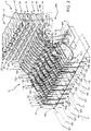
- Washing unit 1 substantially comprises ( Figure 1 ):
- Washing unit 1 also comprises:
- axes A are vertical and direction F is horizontal and orthogonal to axes A of articles 2.
- Feeding system 8 comprises, with special reference to Figures 3 to 7 :
- each sequence 21 is formed by only forward most article 2, with reference to the advancing direction of articles 2 parallel to direction F.
- rows 101 are aligned parallel to direction F.
- Sequencing device 105 comprises a frame 109.
- sequencing device 105 comprises, for each channel 104,:
- Axes B, C are, in the embodiment shown, parallel to one another.
- Axes B, C are, in the embodiment shown, orthogonal to axis A and direction F.
- Sequencing device 105 also comprises a pair of not shown actuators for causing the rotation of lever 107 with respect to frame 109 about axis B and the rotation of lever 108 with respect to lever 107 about axis C.
- each sequencing device 105 can transfer, one after the other, forwardmost article 2 of respective row 101 towards inlet station I of washing tunnel 3 with the right position, horizontal in the embodiment shown.
- sequencing device 105 can transfer article 2 of respective channel 104 along a not circular arch.
- Path P comprises a work branch Q and a return branch R.
- Work branch Q extends from inlet station I to outlet station 0 while return branch R extends from outlet station 0 to return station I.
- path P lies on a vertical plane, and conveyors 8, 14 advance articles 2 along a horizontal direction.
- path P lies in a plane parallel to direction F and orthogonal to axes A, B, C.
- treatment zones 5 comprise a prewash zone, a first cleaning zone, a second cleaning zone.
- the prewash zone, the first cleaning zone, the second cleaning zone comprise respective baths 11, 12, 13 filled with a cleaning agent.
- Treatment zones 5 also comprises a rinsing zone 9, which is aimed to remove the chemical agents out of articles 2 and to cool them down.
- Rinsing zone 9 comprises a plurality of sprinkling devices acting one after the other on articles 2.
- Chain conveyor 4 advances articles 2 along work branch Q and returns without articles 2 along return branch R.
- Bath 11, 12, 13 and rinsing zone 9 are arranged, in this succession, along work branch Q of path P.
- chain conveyor 4 comprises, along work branch Q:
- Return branch R of path P comprises, proceeding from station 0 to station I:
- chain conveyor 4 comprises:
- Chain conveyor 4 further comprises a stationary guide 80 for supporting chains 15.
- Guide 80 is shaped in the same way as path P.
- Each beam 16 comprises a plurality of seats 17 for holding relative articles 2.
- Each beam 16 is adapted to receive forwardmost articles 2 of respective rows 101 from sequencing device 105.
- articles 2 of each row 101 are transferred by sequencing device 105 to respective seats 17 of beam 16 travelling at inlet station I.
- washing unit 1 comprises:
- sensing group 30 is adapted to detect a number N of feeding channels 104 prevented at inlet station I from feeding chain conveyor 4 with the forward most article 2.
- sensing group 30 may comprise ( Figures 3 to 7 ) :
- each sensor 110 is operatively connected to a respective stopping device 120.
- each sensor 110 is configured to detect the correct position of articles 2 on a respective channel 104 of relative conveyor 103 and to generate respective signals in case of absence of articles 2 and/or wrong positioning of articles 2 on respective channel 104.
- Each stopping device 120 can be displaced:
- Each stopping device 120 is arranged downstream of relative sensor 110, proceeding along direction F parallel to the advancing sense of relative conveyor 103, i.e. towards sequencing device 105.
- Each stopping device 120 is arranged at an end 130 of respective channel 104 adjacent to sequencing device 105.
- each stopping device 120 prevents, when set in relative stop position, article 2 from reaching sequencing device 105 and, therefore, from reaching inlet station I of chain conveyor 4.
- control unit 114 is operatively connected with sensors 110 and stopping devices 120.
- control unit 114 is configured to displace each stopping device 120 in the stop position if corresponding sensor 110 generates respective signal, i.e. if corresponding sensor 110 detects the absence or the incorrect position of one article 2 on respective channel 104 of respective conveyor 103.
- stopper devices 120 stop articles 2 at end 130 adjacent to sequencing device 105, articles 2 are substantially prevented from falling on channels 104 without being removed upstream of sequencing device 105.
- Control unit 114 is also configured to displace each stopping device 120 in the rest position if corresponding sensor 110 does not generate respective signal, i.e. if corresponding sensor 110 detects the correct position of article 2 on respective channel 104 of relative conveyor 103.
- Control unit 114 is configured to generate a warning signal, preferably an acoustic signal, when one of sensors 110 has detected the absence of at least one article 2 and/or wrong positioning of at least one article 2 on respective channel 104 ( Figure 5 ).
- respective stopping device 120 is set in the relative stop position, and an operator may remove article 2 from respective channel 104.
- control unit 114 moves back respective stopping device 120 in the relative rest position.
- Control unit 114 is also programmed to arrest one or more conveyors 103 in cases relative sensors 110 have detected the absence of at least one articles 2 and/or wrong positioning of article 2 on a number N of channels 104 greater than a threshold value N 0 .
- sensor 110 is a contact sensor, which contacts articles 2 when the latter are arranged in the correct positions on relative conveyor 103 and remains detached from articles 2 when the latter are arranged in the wrong positions and/or are missing on conveyor 103.
- sensor 110 may be a presence detector, for example an inductive sensor.
- Each sensor 110 may comprise, in particular, ( Figures 3 to 7 ):
- Axis D is, in the embodiment shown, parallel to axis A, B.
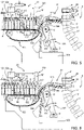
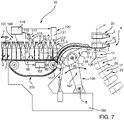
- sensor 110 When articles 2 are arranged in the correct position on conveyor 103, sensor 110 is normally set in a first position ( Figure 3 , 6 and 7 ) in which finger 116 is sloped with respect to axis A and extends on the side of sequencing device 105.
- finger 116 cooperates, on the opposite side thereof with respect to sequencing device 105, with neck portions 91 of articles 2 travelling on conveyor 103.
- sensor 110 When articles 2 are arranged in the wrong position or are missing on conveyor 103, sensor 110 is set in a second position ( Figures 4 and 5 ) in which finger 116 is parallel to axis A. Thus, on the basis of the position of finger 116 it is possible to detect whether or not articles 2 are correctly positioned on conveyor 103.
- Stopping device 120 comprises a housing 121 fitted to a fixed structure and piston 122 which protrudes from housing 121 and can be extended or retracted vertically towards and away from conveyor 103.
- piston 122 When stopping device 120 is in the rest position, piston 122 is retracted and remains detached from articles 2 travelling on conveyor 103 ( Figures 3 , 6 and 7 ).
- piston 122 When stopping device 120 in the stop position, piston 122 is extended and contacts body 92 of articles 2 travelling on conveyor 103 ( Figures 4 and 5 ). Preferably, piston 122 contacts a lateral side of the downstreamest article 2.
- Control unit 114 is also operatively connected with a not-shown driving unit of chain conveyor 4 to adjust the speed of chain conveyor 4, on the basis of number N of channels 104 along which articles 2 are prevented from advancing by respective stopping devices 120 set in respective stop positions ( Figure 1 ).
- control unit 114 is programmed to adjust the speed of chain conveyor 4 in such a way that the throughput of washed articles 2 remains constant even if articles 2 are prevented from advancing along one or more channels 104, and one or more seats 17 can therefore neither receive nor deliver relative articles 2.
- control unit 114 increases the speed of chain conveyor 4.
- control unit 114 decreases the speed of chain conveyor 4.
- Control unit 114 is also operatively connected to motor 102 and to chain conveyor 4.
- control unit 114 is programmed to adjust the speed of chain conveyor 4, as soon as empty seats 17, corresponding to number of channels 104 which are not feeding articles 2, reach outlet station 0.
- washing unit 1 is described in detail in the following, with reference to only one sensor 110 and stopping device 120 arranged in only one channel 104 of relative only one conveyor 103.
- Feeding system 8 advances a plurality of rows 101 of articles 2 to be cleaned inside channel 104 defined by conveyor 103 and parallel to direction F.
- stopping device 120 is set in the rest position, in which it allows articles 2 to advance on channel 104.
- piston 122 is retracted and is detached from necks 91 of articles 2 travelling on conveyor 103.
- Articles 2 properly positioned are arranged with respective axes A vertical, orthogonal to direction F, and with respective bottoms 90 lying on conveyor 103.
- Articles 2 not properly positioned are, for example, arranged with respective axes A parallel to direction F.
- Sensor 110 detects the correct/incorrect position of articles 2 on channel 104 as well as the presence/absence of articles 2.
- sensor 110 is set in the first position shown in Figure 3 .
- articles 2 keep finger 116 sloped with respect to vertical axis.
- sensor 110 is set in the second position shown in Figures 2 , 4 and 5 and generates the signal.
- control unit 114 sets stopping device 120 in the stop position ( Figure 4 ), in which piston 122 is extended and contacts body 92 of articles 2.
- control unit 114 sets stopping device 120 again in the rest position.
- the flow of articles 2 along conveyor 103 can thus start again ( Figure 6 ).
- stopper 120 stops articles 2 at end 130.
- Control unit 114 is also programmed to arrest conveyor 103, in case number of sensors 110 generating respective signals is greater than a threshold value N 0 .
- Sequencing device 105 receives again articles 2 from channels 104 and feeds them to inlet station I of washing tunnel 3 ( Figure 7 ).
- Beams 16 of chain conveyor 4 withdraw respective columns 20 of articles 2 at inlet station I from sequencing device 105, advance articles 2 inside washing tunnel 3 along work branch Q, discharge column 20 of cleaned articles 2 at outlet station O onto outfeed conveyor 14 and return along return branch R without articles 2.
- Control unit 114 adjusts the speed of chain conveyor 4 on the basis of number of empty seats 17, namely number N, to control the actual throughput, for example in order to keep constant the throughput of washing unit 5.
- control unit 114 evaluates number N of channels 104 along which articles 2 are prevented from advancing and calculates the time necessary to empty seats 17 to reach outlet station 0.
- control unit 114 increases (or decreases) the speed of chain conveyor 4. As a matter of fact, if number N is increasing the number of articles 2 actually conveyed by chain conveyor 4 decreases and vice versa.
- control unit 114 also adjusts the speed of chain conveyor 4 when empty seats 17 reach outlet station 0.
- washing unit 1 From an analysis of the features of washing unit 1 and of method according to the present invention, the advantages it allows to obtain are apparent.
- washing unit 1 comprises:
- the speed of chain conveyor 4 can be adjusted on the basis of the correct number of missing articles 2, thus leading to a more controlled value of the final throughout of washing unit 1.
- Sensing group 30 may also comprise stopping devices 120, which stop respective forwardmost articles 2 at ends 130 of relative channels 104 immediately adjacent to sequencing device 105, whenever necessary.
- washing unit 1 and method as described and illustrated herein without, however, departing from the scope of protection as defined in the accompanying claims.
Landscapes
- Engineering & Computer Science (AREA)
- Mechanical Engineering (AREA)
- Control Of Conveyors (AREA)
- Intermediate Stations On Conveyors (AREA)
Claims (16)
- Unité de lavage (1) pour traiter des articles vides (2), comprenant :- une pluralité de canaux d'alimentation (104) pour faire avancer des rangées respectives (101) formées chacune d'une pluralité respective desdits articles vides (2) ; et- un convoyeur à chaîne (4) avec des sièges (17) et mobile cycliquement entre une station d'entrée (I) au niveau de laquelle lesdits sièges (17) sont alimentés, lors de l'utilisation, par lesdits canaux d'alimentation (104) avec des séquences respectives (21) d'un ou de plusieurs desdits articles vides (2) à laver et une station de sortie (O) au niveau de laquelle il décharge, lors de l'utilisation, lesdits articles vides lavés (2) ;- un groupe de capteurs (30) pour capter le nombre de sièges (17) qui ne reçoivent pas lesdits articles (2) ; caractérisée en ce qu'elle comprend :- une unité de commande (114) connectée fonctionnellement audit groupe de capteurs (30) et audit convoyeur à chaîne (4) et programmée pour ajuster la vitesse dudit convoyeur à chaîne (4) sur la base dudit nombre de sièges (17) qui ne reçoivent pas lesdits articles (2), préférablement de façon à maintenir constant le volume traité de ladite unité de lavage (1).
- Unité de lavage selon la revendication 1, caractérisée en ce que ledit groupe de capteurs (30) est conçu pour détecter une quantité associée au nombre (N) de canaux d'alimentation (104) empêchés, lors de l'utilisation, au niveau de ladite station d'entrée (I), d'alimenter ledit convoyeur à chaîne (4) avec ladite séquence respective (21).
- Unité de lavage selon la revendication 1 ou la revendication 2, caractérisée en ce que ladite unité de commande (114) est configurée pour générer un signal d'avertissement, au cas où la vitesse dudit convoyeur à chaîne (4) nécessaire pour maintenir constant ledit volume traité est supérieure à une valeur seuil.
- Unité de lavage selon l'une quelconque des revendications précédentes, caractérisée en ce que ladite unité de commande (114) est configurée pour ajuster de façon continue la vitesse dudit convoyeur à chaîne (14).
- Unité de lavage selon l'une quelconque des revendications précédentes, caractérisée en ce que ledit groupe de capteurs (30) comprend :- une pluralité de capteurs (110), qui sont configurés pour détecter la présence et/ou la position correcte desdits articles vides (2) sur lesdits canaux (104) et sont configurés pour générer lesdits signaux respectifs en cas d'absence desdits articles vides (2) et/ou de mauvaise position desdits articles vides (2) ; et- une pluralité de dispositifs d'arrêt (120), qui sont connectés fonctionnellement auxdits capteurs respectifs (110) et peuvent être déplacés dans des positions d'arrêt respectives, dans lesquelles ils empêchent lesdits articles vides (2) d'avancer sur lesdits canaux respectifs (104) si lesdits capteurs respectifs (110) génèrent lesdits signaux respectifs ;lesdits capteurs (110) et lesdits dispositifs d'arrêt (120) étant connectés fonctionnellement à ladite unité de commande (114).
- Unité de lavage selon l'une quelconque des revendications précédentes, caractérisée en ce qu'elle comprend un dispositif de séquençage (105) qui est conçu pour séparer lesdites séquences (21) desdites rangées (101) et pour convoyer lesdites séquences (21) vers ladite station d'entrée (I).
- Unité de lavage selon la revendication 6, lorsqu'elle dépend de la revendication 5, caractérisée en ce que chaque dit dispositif d'arrêt (120) est configuré pour stopper lesdits articles vides (2) de ladite rangée respective (101) au niveau d'une extrémité (130) dudit canal respectif (104) adjacent audit dispositif de séquençage (105).
- Unité de lavage selon la revendication 7, caractérisée en ce que chaque dite séquence (21) est formée uniquement par un article vide le plus en avant (2) de ladite rangée relative (101), par rapport au sens d'avancée desdits articles (2) sur ledit canal relatif (104) ;ledit convoyeur à chaîne (4) comprenant une pluralité de sièges (17) qui peuvent être alimentés avec des articles vides les plus en avant respectifs (2) de canaux respectifs (104), par rapport au sens d'avancée desdits articles vides (2) sur lesdits canaux respectifs (104) ; etau moins l'un desdits sièges (17) se déplaçant, lors de l'utilisation, vide au cas où il n'est pas alimenté avec ledit article vide respectif (2) ;ladite unité de commande (114) étant programmée pour ajuster ladite vitesse dudit convoyeur à chaîne (4) dès que ledit au moins un siège vide (17), correspondant au canal (104) qui n'alimente en articles (2), atteint ladite station de sortie (O).
- Procédé de lavage d'une pluralité d'articles vides (2), comprenant les étapes consistant à :i) faire avancer une pluralité de rangées (101) d'articles vides (2) le long de canaux d'alimentation respectifs (104) ;ii) convoyer cycliquement lesdits articles vides (2) à laver entre une station d'entrée (I) et une station de sortie (O) au moyen d'un convoyeur à chaîne (4) avec des sièges (17) ; etiii) alimenter lesdits sièges (17) dudit convoyeur à chaîne (4) au niveau de ladite station d'entrée (I) avec des séquences respectives (21) d'un ou de plusieurs desdits articles vides (2) ;iv) détecter le nombre desdits sièges (17) qui ne reçoivent pas lesdits articles (2) ;
caractérisé en ce qu'il comprend les étapes consistant à :
v) ajuster la vitesse dudit convoyeur à chaîne (4) sur la base dudit nombre de sièges (17) qui ne reçoivent pas lesdits articles (2), préférablement de façon à maintenir constant le volume traité de ladite unité de lavage (1). - Procédé selon la revendication 9, caractérisé en ce qu'il comprend l'étape vi) consistant à détecter une quantité associée au nombre (N) de canaux d'alimentation (104) empêchés, au niveau de ladite station d'entrée (I), d'alimenter ledit convoyeur à chaîne (4) avec des séquences respectives (21) d'un ou de plusieurs desdits articles vides (2).
- Procédé selon la revendication 9 ou la revendication 10, caractérisé en ce qu'il comprend une étape vii) consistant à générer un signal d'avertissement au cas où la vitesse dudit convoyeur à chaîne (4) est supérieure à une valeur seuil.
- Procédé selon l'une quelconque des revendications 9 à 11, caractérisé en ce qu'il comprend une étape viii) consistant à ajuster de façon continue ladite vitesse.
- Procédé selon l'une quelconque des revendications 9 à 12, caractérisé en ce que ladite étape iv) comprend les étapes consistant à :ix) détecter la présence et/ou la position correcte desdits articles vides (2) sur lesdits canaux (104) et générer des signaux relatifs en cas d'absence desdits articles vides (2) et/ou de mauvaise position desdits articles vides (2) ; etx) empêcher lesdits articles vides (2) d'avancer sur lesdits canaux respectifs (104) si lesdits signaux sont générés.
- Procédé selon l'une quelconque des revendications 9 à 13, caractérisé en ce qu'il comprend l'étape xi) consistant à séparer lesdites séquences (21) desdites rangées (101) et à convoyer lesdites séquences vers ladite station d'entrée (I).
- Procédé selon la revendication 14, lorsqu'elle dépend de la revendication 13, caractérisé en ce que ladite étape xi) est réalisée au niveau d'une extrémité (130) dudit canal respectif (104) adjacent audit dispositif de séquençage (105).
- Procédé selon la revendication 15, caractérisé en ce que ladite étape iii) comprend une étape xii) consistant à alimenter ledit convoyeur à chaîne (4) au niveau de ladite station d'entrée (I) avec lesdites séquences (21) formées desdits articles vides les plus en avant (2) desdites rangées (101), en procédant selon le sens d'avancée desdits articles vides (2) le long desdits canaux (104) ;
ledit procédé comprenant en outre les étapes consistant à :xiii) alimenter des sièges respectifs (17) dudit convoyeur à chaîne (104) avec lesdits articles les plus en avant (2) réglés dans ladite position correcte ;xiv) convoyer comme vide au moins un dit siège (17) si au moins un article vide le plus en avant correspondant (2) est empêché d'avancer sur ledit convoyeur (103) ;
etxv) ajuster ladite vitesse dès que ledit siège vide (17), correspondant aux canaux (104) qui n'alimentent pas en articles (2), atteint ladite station de sortie (O).
Priority Applications (4)
| Application Number | Priority Date | Filing Date | Title |
|---|---|---|---|
| EP17170863.9A EP3401028B1 (fr) | 2017-05-12 | 2017-05-12 | Unité de lavage pour traiter des articles vides |
| PCT/EP2018/061294 WO2018206381A1 (fr) | 2017-05-12 | 2018-05-03 | Unité de lavage destinée à traiter des articles vides |
| MX2019013459A MX2019013459A (es) | 2017-05-12 | 2018-05-03 | Una unidad de lavado para tratar articulos vacios. |
| ARP180101238A AR111860A1 (es) | 2017-05-12 | 2018-05-10 | Unidad de lavado para tratar artículos vacíos |
Applications Claiming Priority (1)
| Application Number | Priority Date | Filing Date | Title |
|---|---|---|---|
| EP17170863.9A EP3401028B1 (fr) | 2017-05-12 | 2017-05-12 | Unité de lavage pour traiter des articles vides |
Publications (2)
| Publication Number | Publication Date |
|---|---|
| EP3401028A1 EP3401028A1 (fr) | 2018-11-14 |
| EP3401028B1 true EP3401028B1 (fr) | 2022-10-19 |
Family
ID=58709306
Family Applications (1)
| Application Number | Title | Priority Date | Filing Date |
|---|---|---|---|
| EP17170863.9A Active EP3401028B1 (fr) | 2017-05-12 | 2017-05-12 | Unité de lavage pour traiter des articles vides |
Country Status (4)
| Country | Link |
|---|---|
| EP (1) | EP3401028B1 (fr) |
| AR (1) | AR111860A1 (fr) |
| MX (1) | MX2019013459A (fr) |
| WO (1) | WO2018206381A1 (fr) |
Families Citing this family (6)
| Publication number | Priority date | Publication date | Assignee | Title |
|---|---|---|---|---|
| DE102019130414A1 (de) * | 2019-11-12 | 2021-05-12 | Krones Ag | Synchronisation der Behälter Zu- und Abgabevorrichtung |
| DE102020111345A1 (de) * | 2020-04-27 | 2021-10-28 | Khs Gmbh | Steuerung einer Behälterreinigungsmaschine in Abhängigkeit vom Behälterdurchsatz einer nachgelagerten Behälterbehandlungsanlage/-maschine |
| DE102021128817A1 (de) | 2021-11-05 | 2023-05-11 | Khs Gmbh | Zuführeinrichtung und Zuführverfahren für die Zuführung und die Übergabe von Behältern in eine Behälterreinigungsmaschine |
| DE102022117465A1 (de) * | 2022-07-13 | 2024-01-18 | Khs Gmbh | Auf- und/oder Abgabevorrichtung sowie Verfahren zur parallelen Auf- und/oder Abgabe von Behältern |
| DE102022117996A1 (de) * | 2022-07-19 | 2024-01-25 | Khs Gmbh | Scheibenwelle für eine Auf- und/oder Abgabevorrichtung zur Behälterbehandlung |
| EP4331737A1 (fr) * | 2022-08-30 | 2024-03-06 | Sidel Participations | Machine à laver de récipients vides conçue pour être remplie d'un produit versable et procédé associé |
Family Cites Families (6)
| Publication number | Priority date | Publication date | Assignee | Title |
|---|---|---|---|---|
| DE1913730C3 (de) * | 1968-03-22 | 1975-10-02 | Barry-Wehmiller Co., Saint Louis, Mo. (V.St.A.) | Flaschenförderer |
| DE3136510A1 (de) * | 1981-09-15 | 1983-09-22 | Seitz Enzinger Noll Maschinenbau Ag, 6800 Mannheim | Verfahren und vorrichtung zum steuern der flaschenzufoerderung zu einer flaschenreingigungsmaschine |
| JPH09323796A (ja) * | 1996-05-30 | 1997-12-16 | Mitsubishi Heavy Ind Ltd | 容器検出装置 |
| JP2000072232A (ja) * | 1998-08-31 | 2000-03-07 | Shibuya Kogyo Co Ltd | 給びん装置 |
| EP2727760B1 (fr) | 2012-10-31 | 2016-05-25 | Yamaha Hatsudoki Kabushiki Kaisha | Appareil d'entraînement destiné à être utilisé dans un véhicule électrique et ledit véhicule |
| EP2727660B1 (fr) | 2012-11-05 | 2015-08-26 | Gebo Packaging Solutions Italy SRL | Unité de traitement de récipients et procédé pour la reconfiguration d'une unité de traitement de récipients |
-
2017
- 2017-05-12 EP EP17170863.9A patent/EP3401028B1/fr active Active
-
2018
- 2018-05-03 MX MX2019013459A patent/MX2019013459A/es unknown
- 2018-05-03 WO PCT/EP2018/061294 patent/WO2018206381A1/fr not_active Ceased
- 2018-05-10 AR ARP180101238A patent/AR111860A1/es active IP Right Grant
Also Published As
| Publication number | Publication date |
|---|---|
| EP3401028A1 (fr) | 2018-11-14 |
| MX2019013459A (es) | 2020-01-15 |
| AR111860A1 (es) | 2019-08-28 |
| WO2018206381A1 (fr) | 2018-11-15 |
Similar Documents
| Publication | Publication Date | Title |
|---|---|---|
| EP3401028B1 (fr) | Unité de lavage pour traiter des articles vides | |
| EP3401027B1 (fr) | Système et procédé d'alimentation permettant d'alimenter une unité de lavage en articles vides | |
| US6772872B2 (en) | Apparatus for diverting successive articles in a single lane to plural lanes | |
| CN110723515B (zh) | 用于缓冲成件物品的装置和方法 | |
| US9833940B2 (en) | System for feeding preforms | |
| US9815632B2 (en) | Low-energy roller-belt accumulator | |
| EP3747562B1 (fr) | Système d'alimentation et procédé associé pour alimenter un dispositif de transport d'une unité de lavage de contenants vides | |
| US20210403250A1 (en) | Device for grouping containers | |
| WO2002028720A1 (fr) | Dispositif de remplissage aseptique | |
| GB2234727A (en) | Process and apparatus for feeding articles such as bottles. | |
| EP3696119A1 (fr) | Dispositif pour inverser des conteneurs en forme de boîte et procédé correspondant | |
| US3244267A (en) | Convergence apparatus | |
| CN114787821A (zh) | 用于输送产品的装置和方法 | |
| EP2740495A1 (fr) | Unité et procédé de stérilisation de capuchons devant être appliqués sur des récipients | |
| EP3572360B1 (fr) | Unité de traitement pour laver des articles vides et procédé associé | |
| EP3342734B1 (fr) | Convoyeur à chaîne servant à transporter une pluralité d'articles et procédé de détection de l'état d'usure du convoyeur à chaîne | |
| EP3656479B1 (fr) | Machine à laver et procédé relatif de lavage de récipients vides | |
| US5862651A (en) | Flight bar grouper for packer | |
| EP3546079B1 (fr) | Partie d'extrémité pour une poche de réception d'articles vides devant être lavés et avancés le long d'un trajet de traitement de lavage | |
| CN217595445U (zh) | 具有阻挡元件的容器清洁机 | |
| CN101959775A (zh) | 具有可移动的封盖推动器的封盖传送单元 | |
| EP3546078A1 (fr) | Unité de lavage pour laver des articles vides et procédé associé | |
| JP2008296939A (ja) | 容器整列装置 | |
| EP4331737A1 (fr) | Machine à laver de récipients vides conçue pour être remplie d'un produit versable et procédé associé | |
| EP1144280A2 (fr) | Dispositif permettant d'espacer a un intervalle predefini des recipients generalement en plastique, comprenant un element de separation et de freinage des recipients |
Legal Events
| Date | Code | Title | Description |
|---|---|---|---|
| PUAI | Public reference made under article 153(3) epc to a published international application that has entered the european phase |
Free format text: ORIGINAL CODE: 0009012 |
|
| STAA | Information on the status of an ep patent application or granted ep patent |
Free format text: STATUS: THE APPLICATION HAS BEEN PUBLISHED |
|
| AK | Designated contracting states |
Kind code of ref document: A1 Designated state(s): AL AT BE BG CH CY CZ DE DK EE ES FI FR GB GR HR HU IE IS IT LI LT LU LV MC MK MT NL NO PL PT RO RS SE SI SK SM TR |
|
| AX | Request for extension of the european patent |
Extension state: BA ME |
|
| STAA | Information on the status of an ep patent application or granted ep patent |
Free format text: STATUS: REQUEST FOR EXAMINATION WAS MADE |
|
| 17P | Request for examination filed |
Effective date: 20190416 |
|
| RBV | Designated contracting states (corrected) |
Designated state(s): AL AT BE BG CH CY CZ DE DK EE ES FI FR GB GR HR HU IE IS IT LI LT LU LV MC MK MT NL NO PL PT RO RS SE SI SK SM TR |
|
| GRAP | Despatch of communication of intention to grant a patent |
Free format text: ORIGINAL CODE: EPIDOSNIGR1 |
|
| STAA | Information on the status of an ep patent application or granted ep patent |
Free format text: STATUS: GRANT OF PATENT IS INTENDED |
|
| INTG | Intention to grant announced |
Effective date: 20220304 |
|
| GRAS | Grant fee paid |
Free format text: ORIGINAL CODE: EPIDOSNIGR3 |
|
| GRAA | (expected) grant |
Free format text: ORIGINAL CODE: 0009210 |
|
| STAA | Information on the status of an ep patent application or granted ep patent |
Free format text: STATUS: THE PATENT HAS BEEN GRANTED |
|
| AK | Designated contracting states |
Kind code of ref document: B1 Designated state(s): AL AT BE BG CH CY CZ DE DK EE ES FI FR GB GR HR HU IE IS IT LI LT LU LV MC MK MT NL NO PL PT RO RS SE SI SK SM TR |
|
| REG | Reference to a national code |
Ref country code: GB Ref legal event code: FG4D |
|
| REG | Reference to a national code |
Ref country code: CH Ref legal event code: EP |
|
| REG | Reference to a national code |
Ref country code: DE Ref legal event code: R096 Ref document number: 602017062725 Country of ref document: DE |
|
| REG | Reference to a national code |
Ref country code: IE Ref legal event code: FG4D |
|
| REG | Reference to a national code |
Ref country code: AT Ref legal event code: REF Ref document number: 1525239 Country of ref document: AT Kind code of ref document: T Effective date: 20221115 |
|
| REG | Reference to a national code |
Ref country code: LT Ref legal event code: MG9D |
|
| REG | Reference to a national code |
Ref country code: NL Ref legal event code: MP Effective date: 20221019 |
|
| REG | Reference to a national code |
Ref country code: AT Ref legal event code: MK05 Ref document number: 1525239 Country of ref document: AT Kind code of ref document: T Effective date: 20221019 |
|
| PG25 | Lapsed in a contracting state [announced via postgrant information from national office to epo] |
Ref country code: NL Free format text: LAPSE BECAUSE OF FAILURE TO SUBMIT A TRANSLATION OF THE DESCRIPTION OR TO PAY THE FEE WITHIN THE PRESCRIBED TIME-LIMIT Effective date: 20221019 |
|
| PG25 | Lapsed in a contracting state [announced via postgrant information from national office to epo] |
Ref country code: SE Free format text: LAPSE BECAUSE OF FAILURE TO SUBMIT A TRANSLATION OF THE DESCRIPTION OR TO PAY THE FEE WITHIN THE PRESCRIBED TIME-LIMIT Effective date: 20221019 Ref country code: PT Free format text: LAPSE BECAUSE OF FAILURE TO SUBMIT A TRANSLATION OF THE DESCRIPTION OR TO PAY THE FEE WITHIN THE PRESCRIBED TIME-LIMIT Effective date: 20230220 Ref country code: NO Free format text: LAPSE BECAUSE OF FAILURE TO SUBMIT A TRANSLATION OF THE DESCRIPTION OR TO PAY THE FEE WITHIN THE PRESCRIBED TIME-LIMIT Effective date: 20230119 Ref country code: LT Free format text: LAPSE BECAUSE OF FAILURE TO SUBMIT A TRANSLATION OF THE DESCRIPTION OR TO PAY THE FEE WITHIN THE PRESCRIBED TIME-LIMIT Effective date: 20221019 Ref country code: FI Free format text: LAPSE BECAUSE OF FAILURE TO SUBMIT A TRANSLATION OF THE DESCRIPTION OR TO PAY THE FEE WITHIN THE PRESCRIBED TIME-LIMIT Effective date: 20221019 Ref country code: ES Free format text: LAPSE BECAUSE OF FAILURE TO SUBMIT A TRANSLATION OF THE DESCRIPTION OR TO PAY THE FEE WITHIN THE PRESCRIBED TIME-LIMIT Effective date: 20221019 Ref country code: AT Free format text: LAPSE BECAUSE OF FAILURE TO SUBMIT A TRANSLATION OF THE DESCRIPTION OR TO PAY THE FEE WITHIN THE PRESCRIBED TIME-LIMIT Effective date: 20221019 |
|
| PG25 | Lapsed in a contracting state [announced via postgrant information from national office to epo] |
Ref country code: RS Free format text: LAPSE BECAUSE OF FAILURE TO SUBMIT A TRANSLATION OF THE DESCRIPTION OR TO PAY THE FEE WITHIN THE PRESCRIBED TIME-LIMIT Effective date: 20221019 Ref country code: PL Free format text: LAPSE BECAUSE OF FAILURE TO SUBMIT A TRANSLATION OF THE DESCRIPTION OR TO PAY THE FEE WITHIN THE PRESCRIBED TIME-LIMIT Effective date: 20221019 Ref country code: LV Free format text: LAPSE BECAUSE OF FAILURE TO SUBMIT A TRANSLATION OF THE DESCRIPTION OR TO PAY THE FEE WITHIN THE PRESCRIBED TIME-LIMIT Effective date: 20221019 Ref country code: IS Free format text: LAPSE BECAUSE OF FAILURE TO SUBMIT A TRANSLATION OF THE DESCRIPTION OR TO PAY THE FEE WITHIN THE PRESCRIBED TIME-LIMIT Effective date: 20230219 Ref country code: HR Free format text: LAPSE BECAUSE OF FAILURE TO SUBMIT A TRANSLATION OF THE DESCRIPTION OR TO PAY THE FEE WITHIN THE PRESCRIBED TIME-LIMIT Effective date: 20221019 Ref country code: GR Free format text: LAPSE BECAUSE OF FAILURE TO SUBMIT A TRANSLATION OF THE DESCRIPTION OR TO PAY THE FEE WITHIN THE PRESCRIBED TIME-LIMIT Effective date: 20230120 |
|
| P01 | Opt-out of the competence of the unified patent court (upc) registered |
Effective date: 20230418 |
|
| REG | Reference to a national code |
Ref country code: DE Ref legal event code: R097 Ref document number: 602017062725 Country of ref document: DE |
|
| PG25 | Lapsed in a contracting state [announced via postgrant information from national office to epo] |
Ref country code: SM Free format text: LAPSE BECAUSE OF FAILURE TO SUBMIT A TRANSLATION OF THE DESCRIPTION OR TO PAY THE FEE WITHIN THE PRESCRIBED TIME-LIMIT Effective date: 20221019 Ref country code: RO Free format text: LAPSE BECAUSE OF FAILURE TO SUBMIT A TRANSLATION OF THE DESCRIPTION OR TO PAY THE FEE WITHIN THE PRESCRIBED TIME-LIMIT Effective date: 20221019 Ref country code: EE Free format text: LAPSE BECAUSE OF FAILURE TO SUBMIT A TRANSLATION OF THE DESCRIPTION OR TO PAY THE FEE WITHIN THE PRESCRIBED TIME-LIMIT Effective date: 20221019 Ref country code: DK Free format text: LAPSE BECAUSE OF FAILURE TO SUBMIT A TRANSLATION OF THE DESCRIPTION OR TO PAY THE FEE WITHIN THE PRESCRIBED TIME-LIMIT Effective date: 20221019 Ref country code: CZ Free format text: LAPSE BECAUSE OF FAILURE TO SUBMIT A TRANSLATION OF THE DESCRIPTION OR TO PAY THE FEE WITHIN THE PRESCRIBED TIME-LIMIT Effective date: 20221019 |
|
| PLBE | No opposition filed within time limit |
Free format text: ORIGINAL CODE: 0009261 |
|
| STAA | Information on the status of an ep patent application or granted ep patent |
Free format text: STATUS: NO OPPOSITION FILED WITHIN TIME LIMIT |
|
| PG25 | Lapsed in a contracting state [announced via postgrant information from national office to epo] |
Ref country code: SK Free format text: LAPSE BECAUSE OF FAILURE TO SUBMIT A TRANSLATION OF THE DESCRIPTION OR TO PAY THE FEE WITHIN THE PRESCRIBED TIME-LIMIT Effective date: 20221019 Ref country code: AL Free format text: LAPSE BECAUSE OF FAILURE TO SUBMIT A TRANSLATION OF THE DESCRIPTION OR TO PAY THE FEE WITHIN THE PRESCRIBED TIME-LIMIT Effective date: 20221019 |
|
| 26N | No opposition filed |
Effective date: 20230720 |
|
| PG25 | Lapsed in a contracting state [announced via postgrant information from national office to epo] |
Ref country code: SI Free format text: LAPSE BECAUSE OF FAILURE TO SUBMIT A TRANSLATION OF THE DESCRIPTION OR TO PAY THE FEE WITHIN THE PRESCRIBED TIME-LIMIT Effective date: 20221019 |
|
| REG | Reference to a national code |
Ref country code: CH Ref legal event code: PL |
|
| PG25 | Lapsed in a contracting state [announced via postgrant information from national office to epo] |
Ref country code: MC Free format text: LAPSE BECAUSE OF FAILURE TO SUBMIT A TRANSLATION OF THE DESCRIPTION OR TO PAY THE FEE WITHIN THE PRESCRIBED TIME-LIMIT Effective date: 20221019 |
|
| GBPC | Gb: european patent ceased through non-payment of renewal fee |
Effective date: 20230512 |
|
| REG | Reference to a national code |
Ref country code: BE Ref legal event code: MM Effective date: 20230531 |
|
| PG25 | Lapsed in a contracting state [announced via postgrant information from national office to epo] |
Ref country code: MC Free format text: LAPSE BECAUSE OF FAILURE TO SUBMIT A TRANSLATION OF THE DESCRIPTION OR TO PAY THE FEE WITHIN THE PRESCRIBED TIME-LIMIT Effective date: 20221019 Ref country code: LU Free format text: LAPSE BECAUSE OF NON-PAYMENT OF DUE FEES Effective date: 20230512 Ref country code: LI Free format text: LAPSE BECAUSE OF NON-PAYMENT OF DUE FEES Effective date: 20230531 Ref country code: CH Free format text: LAPSE BECAUSE OF NON-PAYMENT OF DUE FEES Effective date: 20230531 |
|
| REG | Reference to a national code |
Ref country code: IE Ref legal event code: MM4A |
|
| PG25 | Lapsed in a contracting state [announced via postgrant information from national office to epo] |
Ref country code: IE Free format text: LAPSE BECAUSE OF NON-PAYMENT OF DUE FEES Effective date: 20230512 |
|
| PG25 | Lapsed in a contracting state [announced via postgrant information from national office to epo] |
Ref country code: IE Free format text: LAPSE BECAUSE OF NON-PAYMENT OF DUE FEES Effective date: 20230512 Ref country code: GB Free format text: LAPSE BECAUSE OF NON-PAYMENT OF DUE FEES Effective date: 20230512 |
|
| PG25 | Lapsed in a contracting state [announced via postgrant information from national office to epo] |
Ref country code: BE Free format text: LAPSE BECAUSE OF NON-PAYMENT OF DUE FEES Effective date: 20230531 |
|
| PG25 | Lapsed in a contracting state [announced via postgrant information from national office to epo] |
Ref country code: BG Free format text: LAPSE BECAUSE OF FAILURE TO SUBMIT A TRANSLATION OF THE DESCRIPTION OR TO PAY THE FEE WITHIN THE PRESCRIBED TIME-LIMIT Effective date: 20221019 |
|
| PG25 | Lapsed in a contracting state [announced via postgrant information from national office to epo] |
Ref country code: BG Free format text: LAPSE BECAUSE OF FAILURE TO SUBMIT A TRANSLATION OF THE DESCRIPTION OR TO PAY THE FEE WITHIN THE PRESCRIBED TIME-LIMIT Effective date: 20221019 |
|
| PGFP | Annual fee paid to national office [announced via postgrant information from national office to epo] |
Ref country code: DE Payment date: 20250423 Year of fee payment: 9 |
|
| PGFP | Annual fee paid to national office [announced via postgrant information from national office to epo] |
Ref country code: IT Payment date: 20250423 Year of fee payment: 9 |
|
| PGFP | Annual fee paid to national office [announced via postgrant information from national office to epo] |
Ref country code: FR Payment date: 20250423 Year of fee payment: 9 |
|
| PG25 | Lapsed in a contracting state [announced via postgrant information from national office to epo] |
Ref country code: CY Free format text: LAPSE BECAUSE OF FAILURE TO SUBMIT A TRANSLATION OF THE DESCRIPTION OR TO PAY THE FEE WITHIN THE PRESCRIBED TIME-LIMIT; INVALID AB INITIO Effective date: 20170512 |
|
| PG25 | Lapsed in a contracting state [announced via postgrant information from national office to epo] |
Ref country code: HU Free format text: LAPSE BECAUSE OF FAILURE TO SUBMIT A TRANSLATION OF THE DESCRIPTION OR TO PAY THE FEE WITHIN THE PRESCRIBED TIME-LIMIT; INVALID AB INITIO Effective date: 20170512 |
|
| PG25 | Lapsed in a contracting state [announced via postgrant information from national office to epo] |
Ref country code: TR Free format text: LAPSE BECAUSE OF FAILURE TO SUBMIT A TRANSLATION OF THE DESCRIPTION OR TO PAY THE FEE WITHIN THE PRESCRIBED TIME-LIMIT Effective date: 20221019 |