EP3401202A1 - Appareil de transmission à pédalier de bicyclette - Google Patents
Appareil de transmission à pédalier de bicyclette Download PDFInfo
- Publication number
- EP3401202A1 EP3401202A1 EP16889549.8A EP16889549A EP3401202A1 EP 3401202 A1 EP3401202 A1 EP 3401202A1 EP 16889549 A EP16889549 A EP 16889549A EP 3401202 A1 EP3401202 A1 EP 3401202A1
- Authority
- EP
- European Patent Office
- Prior art keywords
- aforementioned
- coupled
- gear
- directly
- ratchet
- Prior art date
- Legal status (The legal status is an assumption and is not a legal conclusion. Google has not performed a legal analysis and makes no representation as to the accuracy of the status listed.)
- Granted
Links
Images


Classifications
-
- B—PERFORMING OPERATIONS; TRANSPORTING
- B62—LAND VEHICLES FOR TRAVELLING OTHERWISE THAN ON RAILS
- B62M—RIDER PROPULSION OF WHEELED VEHICLES OR SLEDGES; POWERED PROPULSION OF SLEDGES OR SINGLE-TRACK CYCLES; TRANSMISSIONS SPECIALLY ADAPTED FOR SUCH VEHICLES
- B62M9/00—Transmissions characterised by use of an endless chain, belt, or the like
- B62M9/04—Transmissions characterised by use of an endless chain, belt, or the like of changeable ratio
- B62M9/06—Transmissions characterised by use of an endless chain, belt, or the like of changeable ratio using a single chain, belt, or the like
- B62M9/08—Transmissions characterised by use of an endless chain, belt, or the like of changeable ratio using a single chain, belt, or the like involving eccentrically- mounted or elliptically-shaped driving or driven wheel; with expansible driving or driven wheel
-
- B—PERFORMING OPERATIONS; TRANSPORTING
- B62—LAND VEHICLES FOR TRAVELLING OTHERWISE THAN ON RAILS
- B62M—RIDER PROPULSION OF WHEELED VEHICLES OR SLEDGES; POWERED PROPULSION OF SLEDGES OR SINGLE-TRACK CYCLES; TRANSMISSIONS SPECIALLY ADAPTED FOR SUCH VEHICLES
- B62M21/00—Transmissions characterised by use of resilient elements therein
-
- B—PERFORMING OPERATIONS; TRANSPORTING
- B62—LAND VEHICLES FOR TRAVELLING OTHERWISE THAN ON RAILS
- B62M—RIDER PROPULSION OF WHEELED VEHICLES OR SLEDGES; POWERED PROPULSION OF SLEDGES OR SINGLE-TRACK CYCLES; TRANSMISSIONS SPECIALLY ADAPTED FOR SUCH VEHICLES
- B62M11/00—Transmissions characterised by the use of interengaging toothed wheels or frictionally-engaging wheels
- B62M11/02—Transmissions characterised by the use of interengaging toothed wheels or frictionally-engaging wheels of unchangeable ratio
-
- B—PERFORMING OPERATIONS; TRANSPORTING
- B62—LAND VEHICLES FOR TRAVELLING OTHERWISE THAN ON RAILS
- B62M—RIDER PROPULSION OF WHEELED VEHICLES OR SLEDGES; POWERED PROPULSION OF SLEDGES OR SINGLE-TRACK CYCLES; TRANSMISSIONS SPECIALLY ADAPTED FOR SUCH VEHICLES
- B62M11/00—Transmissions characterised by the use of interengaging toothed wheels or frictionally-engaging wheels
- B62M11/04—Transmissions characterised by the use of interengaging toothed wheels or frictionally-engaging wheels of changeable ratio
- B62M11/14—Transmissions characterised by the use of interengaging toothed wheels or frictionally-engaging wheels of changeable ratio with planetary gears
- B62M11/145—Transmissions characterised by the use of interengaging toothed wheels or frictionally-engaging wheels of changeable ratio with planetary gears built in, or adjacent to, the bottom bracket
-
- B—PERFORMING OPERATIONS; TRANSPORTING
- B62—LAND VEHICLES FOR TRAVELLING OTHERWISE THAN ON RAILS
- B62M—RIDER PROPULSION OF WHEELED VEHICLES OR SLEDGES; POWERED PROPULSION OF SLEDGES OR SINGLE-TRACK CYCLES; TRANSMISSIONS SPECIALLY ADAPTED FOR SUCH VEHICLES
- B62M9/00—Transmissions characterised by use of an endless chain, belt, or the like
- B62M9/04—Transmissions characterised by use of an endless chain, belt, or the like of changeable ratio
- B62M9/06—Transmissions characterised by use of an endless chain, belt, or the like of changeable ratio using a single chain, belt, or the like
-
- F—MECHANICAL ENGINEERING; LIGHTING; HEATING; WEAPONS; BLASTING
- F16—ENGINEERING ELEMENTS AND UNITS; GENERAL MEASURES FOR PRODUCING AND MAINTAINING EFFECTIVE FUNCTIONING OF MACHINES OR INSTALLATIONS; THERMAL INSULATION IN GENERAL
- F16D—COUPLINGS FOR TRANSMITTING ROTATION; CLUTCHES; BRAKES
- F16D41/00—Freewheels or freewheel clutches
- F16D41/06—Freewheels or freewheel clutches with intermediate wedging coupling members between an inner and an outer surface
- F16D41/063—Freewheels or freewheel clutches with intermediate wedging coupling members between an inner and an outer surface the intermediate members wedging by moving along the inner and the outer surface without pivoting or rolling, e.g. sliding wedges
-
- F—MECHANICAL ENGINEERING; LIGHTING; HEATING; WEAPONS; BLASTING
- F16—ENGINEERING ELEMENTS AND UNITS; GENERAL MEASURES FOR PRODUCING AND MAINTAINING EFFECTIVE FUNCTIONING OF MACHINES OR INSTALLATIONS; THERMAL INSULATION IN GENERAL
- F16D—COUPLINGS FOR TRANSMITTING ROTATION; CLUTCHES; BRAKES
- F16D41/00—Freewheels or freewheel clutches
- F16D41/24—Freewheels or freewheel clutches specially adapted for cycles
- F16D41/30—Freewheels or freewheel clutches specially adapted for cycles with hinged pawl co-operating with teeth, cogs, or the like
-
- F—MECHANICAL ENGINEERING; LIGHTING; HEATING; WEAPONS; BLASTING
- F16—ENGINEERING ELEMENTS AND UNITS; GENERAL MEASURES FOR PRODUCING AND MAINTAINING EFFECTIVE FUNCTIONING OF MACHINES OR INSTALLATIONS; THERMAL INSULATION IN GENERAL
- F16H—GEARING
- F16H21/00—Gearings comprising primarily only links or levers, with or without slides
- F16H21/10—Gearings comprising primarily only links or levers, with or without slides all movement being in, or parallel to, a single plane
- F16H21/16—Gearings comprising primarily only links or levers, with or without slides all movement being in, or parallel to, a single plane for interconverting rotary motion and reciprocating motion
- F16H21/18—Crank gearings; Eccentric gearings
-
- B—PERFORMING OPERATIONS; TRANSPORTING
- B62—LAND VEHICLES FOR TRAVELLING OTHERWISE THAN ON RAILS
- B62K—CYCLES; CYCLE FRAMES; CYCLE STEERING DEVICES; RIDER-OPERATED TERMINAL CONTROLS SPECIALLY ADAPTED FOR CYCLES; CYCLE AXLE SUSPENSIONS; CYCLE SIDE-CARS, FORECARS, OR THE LIKE
- B62K19/00—Cycle frames
- B62K19/30—Frame parts shaped to receive other cycle parts or accessories
- B62K19/34—Bottom brackets
-
- B—PERFORMING OPERATIONS; TRANSPORTING
- B62—LAND VEHICLES FOR TRAVELLING OTHERWISE THAN ON RAILS
- B62M—RIDER PROPULSION OF WHEELED VEHICLES OR SLEDGES; POWERED PROPULSION OF SLEDGES OR SINGLE-TRACK CYCLES; TRANSMISSIONS SPECIALLY ADAPTED FOR SUCH VEHICLES
- B62M1/00—Rider propulsion of wheeled vehicles
- B62M1/36—Rider propulsion of wheeled vehicles with rotary cranks, e.g. with pedal cranks
-
- F—MECHANICAL ENGINEERING; LIGHTING; HEATING; WEAPONS; BLASTING
- F16—ENGINEERING ELEMENTS AND UNITS; GENERAL MEASURES FOR PRODUCING AND MAINTAINING EFFECTIVE FUNCTIONING OF MACHINES OR INSTALLATIONS; THERMAL INSULATION IN GENERAL
- F16D—COUPLINGS FOR TRANSMITTING ROTATION; CLUTCHES; BRAKES
- F16D41/00—Freewheels or freewheel clutches
- F16D41/06—Freewheels or freewheel clutches with intermediate wedging coupling members between an inner and an outer surface
- F16D2041/0606—Freewheels or freewheel clutches with intermediate wedging coupling members between an inner and an outer surface the intermediate coupling members having parts wedging by movement other than pivoting or rolling but combined with pivoting or rolling parts, e.g. shoes on pivot bars or on rollers
-
- F—MECHANICAL ENGINEERING; LIGHTING; HEATING; WEAPONS; BLASTING
- F16—ENGINEERING ELEMENTS AND UNITS; GENERAL MEASURES FOR PRODUCING AND MAINTAINING EFFECTIVE FUNCTIONING OF MACHINES OR INSTALLATIONS; THERMAL INSULATION IN GENERAL
- F16H—GEARING
- F16H1/00—Toothed gearings for conveying rotary motion
- F16H1/28—Toothed gearings for conveying rotary motion with gears having orbital motion
- F16H1/32—Toothed gearings for conveying rotary motion with gears having orbital motion in which the central axis of the gearing lies inside the periphery of an orbital gear
- F16H2001/323—Toothed gearings for conveying rotary motion with gears having orbital motion in which the central axis of the gearing lies inside the periphery of an orbital gear comprising eccentric crankshafts driving or driven by a gearing
-
- F—MECHANICAL ENGINEERING; LIGHTING; HEATING; WEAPONS; BLASTING
- F16—ENGINEERING ELEMENTS AND UNITS; GENERAL MEASURES FOR PRODUCING AND MAINTAINING EFFECTIVE FUNCTIONING OF MACHINES OR INSTALLATIONS; THERMAL INSULATION IN GENERAL
- F16H—GEARING
- F16H55/00—Elements with teeth or friction surfaces for conveying motion; Worms, pulleys or sheaves for gearing mechanisms
- F16H55/02—Toothed members; Worms
- F16H55/30—Chain-wheels
Definitions
- the present invention relates to a bicycle transmission apparatus. More specifically, it relates to a hub-gear transmission apparatus that is installed on the crankset of a bicycle.
- a bicycle is provided with a transmission apparatus installed on the crankset and rear wheel axle to ensure efficient cycling.
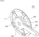
- FIG. 1 illustrates a conventional bicycle crank transmission apparatus.
- the conventional bicycle crank transmission apparatus (100) includes multiple chainrings (110) of different sizes to be installed on the bottom bracket of the bicycle; a front derailleur (120) which, when coupled to the frame (F), moves the chain placed on a certain chainring (110) to another chainring (110); and a shift lever (140) which, coupled to the front derailleur (120) by wire (130) and mounted on the handlebar of the bicycle and which serves to manipulate the front derailleur (120).
- Another limitation of the conventional bicycle crank transmission apparatus (100) is that it is difficult to be made smaller and lighter in weight because it has multiple chainrings (110) stacked in layers and is provided with the shift lever (140) separately as it is coupled to the front derailleur (120) by the wire (130).
- the invention provides a bicycle crank transmission apparatus comprising a hollow shaft member; a base plate which is coupled to the aforementioned shaft member on one side and installed securely on a bottom bracket featuring a spindle on the other side; a chainring housing which is coupled to the aforementioned shaft member in a way that allows its rotation and has a ring gear installed securely inside; a reduction gear unit arranged in the middle of the aforementioned ring gear; a directly-coupled ratchet unit installed on the aforementioned ring gear; a crank cover where a coupling shaft coupled to the aforementioned spindle is perpendicularly provided in the center and where clutch ratchet teeth, which are engaged with the aforementioned directly-coupled ratchet unit, and directly-coupled ratchet teeth are vertically stacked on the internal wall surface; and a sun gear installed on the aforementioned coupling shaft in such a way that it only rotates in clockwise direction and partially engaged with
- the invention is characterized by providing the aforementioned base plate with a BB holder and also by conveniently coupling said BB holder to the aforementioned bottom bracket.
- the aforementioned anti-reverse rotation unit is made up of an internal ratchet gear formed on the aforementioned base plate, an external ratchet gear formed on the aforementioned chainring housing, and an anti-reverse rotation ring which has multiple elastic hooks both on the external and internal circumferences and is arranged between the aforementioned internal ratchet gear and the aforementioned external ratchet gear.
- the aforementioned reduction gear unit consists of an eccentric guide installed securely on the aforementioned shaft member and arranged in the center of the aforementioned ring gear, and an eccentric gear which is provided in a way that allows it to rotate along the external circumference of the aforementioned eccentric guide, and a part of which is engaged with the aforementioned ring gear while another part of which is engaged with the aforementioned sun gear.
- the aforementioned directly-coupled ratchet unit consists of multiple directly-coupled ratchets, which are installed at intervals on the external circumference of the aforementioned ring gear, extend in radial direction, and each have operating protrusions on one side; and a directly-coupled ratchet clutch which is stacked on one side of the aforementioned ring gear, and features indentations where the aforementioned operating protrusions are received in circumferential direction, and supports that support the aforementioned operating protrusions, which are alternately formed at intervals on the internal circumference, with multiple elastic ratchets provided at intervals on the external circumference.
- An advantage of the present invention comprising the above-described components is to eliminate the need for multiple chainrings and an extra shift lever by realizing a shifting mechanism through the reduction gear unit and the directly-coupled ratchet unit provided inside, and to ultimately make the product smaller and lighter.
- Another advantage of the invention is to prevent the chain from falling off from the chainring during a gear shift.
- Yet another advantage of the invention is to allow fast and intuitive gear shifting by rotating the crank arm in anti-clockwise direction.
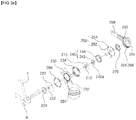
- the bicycle crank transmission apparatus (200) comprises a shaft member (210), a base plate (220), a chainring housing (230), a reduction gear unit (240), a directly-coupled ratchet unit (250), a crank cover (260), and a sun gear (270).
- the shaft member (210) is a disk shape with a predetermined thickness having a hollow (212).
- the shaft member (210) is securely coupled to the base plate (220) described below on one side and, on the other side, the eccentric guide (242) described below is securely installed.
- chainring housing (230) described below is coupled to the shaft member (210) in a way that allows rotation of said housing.
- the base plate (220) is coupled to the shaft member (210) on one side and features in the center a hole (222) with the same diameter as that of the hollow (212) in the shaft member (210).
- the center of said hole (222) preferably has the same axis as that of the hollow (212) formed in the shaft member (210).
- the base plate (220) is securely coupled to the bottom bracket (B) mounted on the bicycle frame (F).
- the base plate (220) preferably has a removable BB holder (224) on the other side.
- the BB holder (224) has a shape that corresponds to the end of the bottom bracket (B) in order to install the present invention on various bottom brackets (B) with different sizes depending on the manufacturer.
- the chainring housing (230) is coupled to the shaft member (210) in a way that allows rotation of the housing.
- an internal ring gear (234) is securely installed on the chainring housing (230), and multiple chainring coupling portions (232) coupled to the chainring (C) are formed at intervals in circumferential direction on the external circumference.
- the chainring housing (230) is made separable from the chainring (C) but the chainring housing (230) may be integrated with the chainring (C) according to the intent of a user.
- An anti-reverse rotation unit (280) is provided between the base plate (220) and the chainring housing (230).
- Such an anti-reverse rotation unit (280) allows the chainring housing (230) to freely rotate in clockwise direction with the shaft member (210) as a reference axis while preventing it from rotating in anti-clockwise direction within limits of a predetermined rotational force.
- the anti-reverse rotation unit (280) consists of an internal ratchet gear (282), an external ratchet gear (284), and an anti-reverse rotation ring (286).
- the internal ratchet gear (282) is stacked on the edge of the base plate (220) while the external ratchet gear (284) is stacked on the center of the chainring housing (230).
- the teeth formed on the internal ratchet gear (282) and the external ratchet gear (284) consist of primary sliding portions (282a, 284a) and secondary sliding portions (282b, 284b). Unlike conventional ratchets, those primary sliding portions (282a, 284a) that constitute pitch surfaces form an acute angle with a pitch circle.
- the anti-reverse rotation ring (286) is arranged between the internal ratchet gear (282) and the external ratchet gear (284) and multiple elastic hooks (286a) are provided at intervals in circumferential direction on the external and internal circumferences.
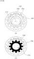
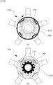
- FIG.4 was prepared based on the rear view of the invention
- the working principle of the anti-reverse rotation unit (280) will be briefly described.
- crank cover (260) When the user rotates the crank cover (260) in anti-clockwise direction to shift gears, the crank cover (260) and the chainring housing (230) will not directly engage, but since they are close enough, a weak force will be transmitted to the chainring housing (230) during rotation.
- the anti-reverse rotation unit (280) ensures the shifting mechanism is smoothly implemented by preventing the chainring housing (230) from rotating in anti-clockwise direction from the shaft member (210) during a gear shift, but causes the chainring housing (230) to rotate in anti-clockwise direction when the bicycle reverses, preventing damage to the bicycle.
- the reduction gear unit (240) consists of the eccentric guide (242) and the eccentric gear (244).
- the eccentric guide (242) has a cylindrical shape and features an eccentric hole (242a) with a certain distance from the center.
- the eccentric guide (242) is securely installed on the other side of the shaft member (210) and then arranged in the center of the ring gear (234).
- the hollow (212) shares the same center as the eccentric hole (242a).
- the eccentric gear (244) is provided in a way that allows it to rotate along the external circumference of the eccentric guide (242). A certain portion of the eccentric gear (244) is engaged with the ring gear (234) and another portion opposite said portion is engaged with the sun gear (270) described below.
- FIG. 5 is a view illustrating the coupling relationship between the reduction gear unit (240) and the ring gear (234).
- the reduction gear unit (240) receives the force of rotation of the crank cover (260) from the sun gear (270) and then rotates the ring gear (234) with the reduced number of revolutions per minute.
- the reduction gear unit (240) rotates in the same direction as the sun gear (270), transmitting the reduced force of rotation to the ring gear (234). It significantly lowers the risk of wear or damage to the reduction gear unit (240) relative to planetary gears (not shown). Furthermore, it increases the durability of the apparatus since it does not cause any force of rotation in reverse direction that may unnecessarily apply to the chainring housing (230), etc.
- the directly-coupled ratchet unit (250) consists of multiple directly-coupled ratchets (252) and a directly-coupled ratchet clutch (254).
- the directly-coupled ratchets (252) are installed on the external circumference of the ring gear (234) and extend in radial direction by means of mechanical elements with elasticity such as springs (252b).
- the extending directly-coupled ratchets (252) are engaged with the directly-ratchet teeth (266) as the crank cover (260) rotates in clockwise direction.
- the directly-coupled ratchets (252) have operating protrusions (252a) on one side.
- the directly-coupled ratchet clutch (254) is installed on one side of the ring gear (234).
- On the internal circumference of the directly-coupled ratchet clutch (254) are provided alternately the indentations (254a), where aforementioned operating protrusions (252a) are received in circumferential direction, and supports (254b), which support the aforementioned operating protrusions (252a).
- On the outer circumference multiple elastic ratchets (254c) are provided at intervals in circumferential direction. The multiple elastic ratchets (254c) are engaged with the clutch ratchet teeth (264) as the crank cover (260) rotates in anti-clockwise direction.
- the crank cover (260) is made in the shape of a drinking cup lid.
- a coupling shaft (262) is provided perpendicularly, which is coupled to the spindle (BS) of the bottom bracket (B).
- the clutch ratchet teeth (264) engaged with the directly-coupled ratchet unit (250) and the directly-coupled ratchet teeth (266) are stacked vertically.
- crank arm (268) In a pre-determined location on the outer circumference of the crank cover (260) is formed a crank arm (268).
- the crank cover (260) is mounted on one side of the chainring housing (230). At the same time, the coupling shaft (262) is coupled to the spindle (BS) after passing through the hollow (212) of the shaft member (210).
- the sun gear (270) is installed in such a way that it only rotates in clockwise direction on the coupling shaft (262) of the crank cover (260). To that end, preferably, a ratchet unit is provided in one direction inside the sun gear (270). As described earlier, the sun gear (270) is partially engaged with the reduction gear unit (240).
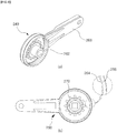
- FIG. 7 a view showing the working principle of the directly-coupled ratchet unit (250), when the crank cover (260) rotates in anti-clockwise direction, the clutch ratchet teeth (264) get engaged with the elastic ratchet (254c), and then the crank cover causes the directly-coupled ratchet clutch (254) to rotate in anti-clockwise direction.
- Reverse rotation of the chainring housing (230) gets blocked by the anti-reverse rotation unit (280). This causes the directly-coupled ratchet clutch (254) to slide against and rotate around the fixed ring gear (234).
- the directly-coupled ratchet clutch (254) rotates at a predetermined angle, the operating protrusions (252a) abutting the internal circumference of the directly-coupled ratchet clutch (254) become received in the indentations (254a) or supported by the supports (254b), causing the directly-coupled ratchet to extend or fold.
- the directly-coupled ratchets (252) extend outside the ring gear (234) by means of elastic mechanical elements, and the extending directly-coupled ratchets (252) get engaged with the directly-coupled ratchet teeth (266).
- the ring gear (234) may get directly coupled to the crank cover (26) and start rotating at the same revolutions per minute.
- the directly-coupled ratchets (252) fold up under pressure, getting disengaged from the directly-coupled ratchet teeth (266). Then, the ring gear (234) may rotate at a lower RPM than the crank cover (260) as it becomes coupled to the sun gear (270) through the reduction gear unit (240).
- the sun gear (270) receives the force of rotation of the ring gear (234) through the reduction gear unit (240) and idles at a higher RPM than the crank cover (260).
- the present invention can directly cause the ring gear (234) to rotate at the same RPM as the crank cover (260), or cause the ring gear (234) to rotate at a reduced RPM through the sun gear (270) and reduction gear unit (240) by rotating the crank cover (260) in anti-clockwise direction and then manipulating the directly-coupled ratchet unit (250).
- the present invention eliminates the need for multiple chainrings and a separate shift level and can thus make products smaller and lighter by realizing the shifting mechanism using the reduction gear unit and directly coupled unit. That is why it has an advantage that it can make products smaller and lighter.
- Another advantage of the invention is to prevent the chain from falling off from the chainring during a gear shift.
- an advantage of the invention is to allow fast and intuitive gear shifting.
Landscapes
- Engineering & Computer Science (AREA)
- General Engineering & Computer Science (AREA)
- Mechanical Engineering (AREA)
- Chemical & Material Sciences (AREA)
- Combustion & Propulsion (AREA)
- Transportation (AREA)
- Transmission Devices (AREA)
- Structure Of Transmissions (AREA)
Applications Claiming Priority (2)
| Application Number | Priority Date | Filing Date | Title |
|---|---|---|---|
| KR1020160014885A KR101701289B1 (ko) | 2016-02-05 | 2016-02-05 | 자전거 크랭크 변속장치 |
| PCT/KR2016/015275 WO2017135572A1 (fr) | 2016-02-05 | 2016-12-26 | Appareil de transmission à pédalier de bicyclette |
Publications (3)
| Publication Number | Publication Date |
|---|---|
| EP3401202A1 true EP3401202A1 (fr) | 2018-11-14 |
| EP3401202A4 EP3401202A4 (fr) | 2019-07-03 |
| EP3401202B1 EP3401202B1 (fr) | 2021-03-31 |
Family
ID=58109406
Family Applications (1)
| Application Number | Title | Priority Date | Filing Date |
|---|---|---|---|
| EP16889549.8A Active EP3401202B1 (fr) | 2016-02-05 | 2016-12-26 | Appareil de transmission à pédalier de bicyclette |
Country Status (6)
| Country | Link |
|---|---|
| US (1) | US10703438B2 (fr) |
| EP (1) | EP3401202B1 (fr) |
| JP (1) | JP6598043B2 (fr) |
| KR (1) | KR101701289B1 (fr) |
| CN (1) | CN108602546B (fr) |
| WO (1) | WO2017135572A1 (fr) |
Cited By (1)
| Publication number | Priority date | Publication date | Assignee | Title |
|---|---|---|---|---|
| IT202300009573A1 (it) * | 2023-05-12 | 2024-11-12 | Magneticdays S R L | Dispositivo per la variazione del rapporto di trasmissione in un veicolo a pedali |
Families Citing this family (10)
| Publication number | Priority date | Publication date | Assignee | Title |
|---|---|---|---|---|
| KR102186944B1 (ko) | 2018-11-23 | 2020-12-04 | 주식회사 콘타벨로 | 변속기 내장형 크랭크 조립체 |
| CN110077518B (zh) * | 2019-04-15 | 2024-04-12 | 湖南速奥科技有限公司 | 一种牙盘、牙盘组件和自行车 |
| TWI721517B (zh) * | 2019-08-01 | 2021-03-11 | 劉文桂 | 自行車變速裝置 |
| CN110576448B (zh) * | 2019-09-10 | 2023-04-07 | 饭团机器人有限公司 | 一种智能服务机器人 |
| US12358593B2 (en) * | 2021-01-15 | 2025-07-15 | Sram, Llc | Bash guard device and system for bicycle components |
| US12522318B2 (en) * | 2021-12-31 | 2026-01-13 | Zwift, Inc. | Single-sprocket system for a bicycle trainer |
| WO2023224713A1 (fr) | 2022-05-18 | 2023-11-23 | Innovative Engineering LLC | Système de transmission automatique pour bicyclette |
| WO2024117716A1 (fr) * | 2022-11-28 | 2024-06-06 | 주식회사 콘타벨로 | Transmission à manivelle de bicyclette |
| KR20240128248A (ko) | 2023-02-17 | 2024-08-26 | 경남정보대학교 산학협력단 | 자전거 크랭크 조립체 |
| KR102784665B1 (ko) | 2024-11-27 | 2025-03-21 | 주식회사 콘타벨로 | 자전거 크랭크 변속장치 |
Family Cites Families (21)
| Publication number | Priority date | Publication date | Assignee | Title |
|---|---|---|---|---|
| US2600586A (en) * | 1949-04-16 | 1952-06-17 | William G Spencer | Automatic bicycle transmission |
| US2972908A (en) * | 1959-05-29 | 1961-02-28 | Bendix Corp | Semi-automatic two-speed hub and coaster brake for velocipedes and the like |
| JPS61115791A (ja) * | 1984-11-12 | 1986-06-03 | ブリヂストンサイクル株式会社 | 無段変速装置の脈動緩衝装置 |
| JPS61115792A (ja) * | 1984-11-12 | 1986-06-03 | ブリヂストンサイクル株式会社 | 無段変速装置の逆入力許容装置 |
| JPS61115791U (fr) * | 1984-12-28 | 1986-07-22 | ||
| US4712450A (en) * | 1985-02-09 | 1987-12-15 | Bridgestone Cycle Co., Ltd. | Stepless speed change device |
| JPS6229485A (ja) * | 1985-07-31 | 1987-02-07 | ブリヂストンサイクル株式会社 | 無段変速装置の逆入力許容装置 |
| JP2599596B2 (ja) * | 1987-07-13 | 1997-04-09 | 株式会社シマノ | 自転車用変速装置 |
| JPS6436594A (en) * | 1987-07-31 | 1989-02-07 | Japan Engine Valve Mfg | Nonstage transmission for bicycle |
| CN87214967U (zh) * | 1987-11-01 | 1988-09-28 | 殷永江 | 自行车变速装置 |
| JPH06239285A (ja) * | 1993-02-15 | 1994-08-30 | Bridgestone Cycle Co | 自転車用変速装置 |
| NZ269778A (en) * | 1993-08-30 | 1997-04-24 | Aimbridge Pty Ltd | Variable ratio rotary transmission: motion transmitted by ratchet and pawl mechanism mounted with variable eccentricity on input shaft |
| KR100195515B1 (ko) * | 1996-12-30 | 1999-06-15 | 마재열 | 자전거의 변환 전진구동 주행의 제어장치 |
| IL133376A0 (en) * | 1997-06-09 | 2001-04-30 | World Ind Co Ltd | Apparatus for changing rotation of pedal shaft for bicycle |
| KR20000046381A (ko) * | 1998-12-31 | 2000-07-25 | 강병호 | 개인 휴대 통신 교환기에서의 신규 가입자에 대한 해피콜 서비스 방법 |
| JP2002079984A (ja) * | 2000-09-08 | 2002-03-19 | Mutsumi Giken Kk | 自転車 |
| JP4398737B2 (ja) * | 2004-01-05 | 2010-01-13 | 隆次 中野 | 自動変速機構及び自動変速機構を有する自転車用ハブ |
| JP2005280591A (ja) * | 2004-03-30 | 2005-10-13 | Fujiwara Wheel:Kk | 自転車用変速装置 |
| KR101195422B1 (ko) * | 2010-05-10 | 2012-10-30 | (주) 에프엑스기어 | 주행속도 향상을 위한 자전거용 가속장치 |
| CN102602503B (zh) * | 2012-04-21 | 2013-07-17 | 叶雪峰 | 反转变速控制机构 |
| KR101587712B1 (ko) * | 2014-05-16 | 2016-01-21 | 현경열 | 동력전달장치 |
-
2016
- 2016-02-05 KR KR1020160014885A patent/KR101701289B1/ko not_active Expired - Fee Related
- 2016-12-26 US US16/072,258 patent/US10703438B2/en active Active
- 2016-12-26 JP JP2018560415A patent/JP6598043B2/ja active Active
- 2016-12-26 CN CN201680080449.0A patent/CN108602546B/zh active Active
- 2016-12-26 EP EP16889549.8A patent/EP3401202B1/fr active Active
- 2016-12-26 WO PCT/KR2016/015275 patent/WO2017135572A1/fr not_active Ceased
Cited By (1)
| Publication number | Priority date | Publication date | Assignee | Title |
|---|---|---|---|---|
| IT202300009573A1 (it) * | 2023-05-12 | 2024-11-12 | Magneticdays S R L | Dispositivo per la variazione del rapporto di trasmissione in un veicolo a pedali |
Also Published As
| Publication number | Publication date |
|---|---|
| US10703438B2 (en) | 2020-07-07 |
| EP3401202B1 (fr) | 2021-03-31 |
| CN108602546A (zh) | 2018-09-28 |
| JP2019506336A (ja) | 2019-03-07 |
| KR101701289B1 (ko) | 2017-02-01 |
| EP3401202A4 (fr) | 2019-07-03 |
| JP6598043B2 (ja) | 2019-10-30 |
| US20190031285A1 (en) | 2019-01-31 |
| WO2017135572A1 (fr) | 2017-08-10 |
| CN108602546B (zh) | 2020-04-14 |
Similar Documents
| Publication | Publication Date | Title |
|---|---|---|
| EP3401202B1 (fr) | Appareil de transmission à pédalier de bicyclette | |
| JP4633719B2 (ja) | 自動変速装置 | |
| TWI336672B (en) | Bicycle hub assembly | |
| TWI400177B (zh) | Bicycle forced transmission | |
| JP3850808B2 (ja) | 自転車用シフト制御装置 | |
| US9103392B2 (en) | Hub with mechanism to permit backwards movement without pedal movement | |
| JP2914909B2 (ja) | 自転車用変速装置内装ハブ | |
| TW200902378A (en) | Mounting system for an internal bicycle transmission | |
| RU2002118712A (ru) | Устройство для переключения передач велосипедов | |
| EP2641820A2 (fr) | Moyeu de roue interne | |
| JP2003513214A (ja) | 歯車装置 | |
| WO2004042252A1 (fr) | Transmission d'arbre d'entrainement de bicyclette | |
| CN107922034B (zh) | 用于自行车的智能传动系统 | |
| JP2009161168A (ja) | 自転車用内装変速ハブ | |
| CN113895558A (zh) | 一种自行车内变速器及轮毂组件 | |
| WO2006033541A1 (fr) | Appareil de sortie automatique permettant de convertir un entrainement bidirectionnel en un entrainement unidirectionnel et velo comprenant celui-ci | |
| CN107250605A (zh) | 加速减速齿轮装置 | |
| JP6400856B2 (ja) | 変速機 | |
| KR102186944B1 (ko) | 변속기 내장형 크랭크 조립체 | |
| KR101260050B1 (ko) | 변속기 | |
| US8900087B2 (en) | Multi-speed inline automatic bicycle transmission | |
| JP7002813B2 (ja) | 自転車駆動装置 | |
| JPS6196252A (ja) | 可変ピツチ径チエ−ン歯車 | |
| KR100944972B1 (ko) | 자동 속도변환장치의 브레이크장치 | |
| CN205124788U (zh) | 可变速的钓鱼用纺车式卷线器 |
Legal Events
| Date | Code | Title | Description |
|---|---|---|---|
| STAA | Information on the status of an ep patent application or granted ep patent |
Free format text: STATUS: THE INTERNATIONAL PUBLICATION HAS BEEN MADE |
|
| PUAI | Public reference made under article 153(3) epc to a published international application that has entered the european phase |
Free format text: ORIGINAL CODE: 0009012 |
|
| STAA | Information on the status of an ep patent application or granted ep patent |
Free format text: STATUS: REQUEST FOR EXAMINATION WAS MADE |
|
| 17P | Request for examination filed |
Effective date: 20180809 |
|
| AK | Designated contracting states |
Kind code of ref document: A1 Designated state(s): AL AT BE BG CH CY CZ DE DK EE ES FI FR GB GR HR HU IE IS IT LI LT LU LV MC MK MT NL NO PL PT RO RS SE SI SK SM TR |
|
| AX | Request for extension of the european patent |
Extension state: BA ME |
|
| RIN1 | Information on inventor provided before grant (corrected) |
Inventor name: JANG, SA SEOK |
|
| DAV | Request for validation of the european patent (deleted) | ||
| DAX | Request for extension of the european patent (deleted) | ||
| RAP1 | Party data changed (applicant data changed or rights of an application transferred) |
Owner name: CONTAVELO CO., LTD. |
|
| A4 | Supplementary search report drawn up and despatched |
Effective date: 20190603 |
|
| RIC1 | Information provided on ipc code assigned before grant |
Ipc: F16H 21/18 20060101ALI20190527BHEP Ipc: F16D 41/06 20060101ALI20190527BHEP Ipc: F16H 1/32 20060101ALI20190527BHEP Ipc: B62M 11/14 20060101ALI20190527BHEP Ipc: B62M 9/06 20060101AFI20190527BHEP Ipc: F16D 41/063 20060101ALI20190527BHEP Ipc: F16H 55/30 20060101ALI20190527BHEP |
|
| STAA | Information on the status of an ep patent application or granted ep patent |
Free format text: STATUS: EXAMINATION IS IN PROGRESS |
|
| 17Q | First examination report despatched |
Effective date: 20200506 |
|
| GRAP | Despatch of communication of intention to grant a patent |
Free format text: ORIGINAL CODE: EPIDOSNIGR1 |
|
| STAA | Information on the status of an ep patent application or granted ep patent |
Free format text: STATUS: GRANT OF PATENT IS INTENDED |
|
| INTG | Intention to grant announced |
Effective date: 20201021 |
|
| RIN1 | Information on inventor provided before grant (corrected) |
Inventor name: JANG, SA SEOK |
|
| GRAS | Grant fee paid |
Free format text: ORIGINAL CODE: EPIDOSNIGR3 |
|
| GRAA | (expected) grant |
Free format text: ORIGINAL CODE: 0009210 |
|
| STAA | Information on the status of an ep patent application or granted ep patent |
Free format text: STATUS: THE PATENT HAS BEEN GRANTED |
|
| AK | Designated contracting states |
Kind code of ref document: B1 Designated state(s): AL AT BE BG CH CY CZ DE DK EE ES FI FR GB GR HR HU IE IS IT LI LT LU LV MC MK MT NL NO PL PT RO RS SE SI SK SM TR |
|
| REG | Reference to a national code |
Ref country code: GB Ref legal event code: FG4D Ref country code: CH Ref legal event code: EP |
|
| REG | Reference to a national code |
Ref country code: AT Ref legal event code: REF Ref document number: 1376649 Country of ref document: AT Kind code of ref document: T Effective date: 20210415 |
|
| REG | Reference to a national code |
Ref country code: DE Ref legal event code: R096 Ref document number: 602016055455 Country of ref document: DE |
|
| REG | Reference to a national code |
Ref country code: IE Ref legal event code: FG4D |
|
| REG | Reference to a national code |
Ref country code: DE Ref legal event code: R082 Ref document number: 602016055455 Country of ref document: DE Representative=s name: BCKIP CHOI KO PATENTANWAELTE UND EUROPEAN PATE, DE Ref country code: DE Ref legal event code: R082 Ref document number: 602016055455 Country of ref document: DE Representative=s name: BCKIP KO & PARTNER PATENTANWAELTE PARTNERSCHAF, DE Ref country code: DE Ref legal event code: R082 Ref document number: 602016055455 Country of ref document: DE Representative=s name: BCKIP BRAUN KO PATENTANWAELTE PARTNERSCHAFT MB, DE |
|
| REG | Reference to a national code |
Ref country code: LT Ref legal event code: MG9D |
|
| PG25 | Lapsed in a contracting state [announced via postgrant information from national office to epo] |
Ref country code: BG Free format text: LAPSE BECAUSE OF FAILURE TO SUBMIT A TRANSLATION OF THE DESCRIPTION OR TO PAY THE FEE WITHIN THE PRESCRIBED TIME-LIMIT Effective date: 20210630 Ref country code: HR Free format text: LAPSE BECAUSE OF FAILURE TO SUBMIT A TRANSLATION OF THE DESCRIPTION OR TO PAY THE FEE WITHIN THE PRESCRIBED TIME-LIMIT Effective date: 20210331 Ref country code: FI Free format text: LAPSE BECAUSE OF FAILURE TO SUBMIT A TRANSLATION OF THE DESCRIPTION OR TO PAY THE FEE WITHIN THE PRESCRIBED TIME-LIMIT Effective date: 20210331 Ref country code: NO Free format text: LAPSE BECAUSE OF FAILURE TO SUBMIT A TRANSLATION OF THE DESCRIPTION OR TO PAY THE FEE WITHIN THE PRESCRIBED TIME-LIMIT Effective date: 20210630 |
|
| PG25 | Lapsed in a contracting state [announced via postgrant information from national office to epo] |
Ref country code: SE Free format text: LAPSE BECAUSE OF FAILURE TO SUBMIT A TRANSLATION OF THE DESCRIPTION OR TO PAY THE FEE WITHIN THE PRESCRIBED TIME-LIMIT Effective date: 20210331 Ref country code: RS Free format text: LAPSE BECAUSE OF FAILURE TO SUBMIT A TRANSLATION OF THE DESCRIPTION OR TO PAY THE FEE WITHIN THE PRESCRIBED TIME-LIMIT Effective date: 20210331 Ref country code: LV Free format text: LAPSE BECAUSE OF FAILURE TO SUBMIT A TRANSLATION OF THE DESCRIPTION OR TO PAY THE FEE WITHIN THE PRESCRIBED TIME-LIMIT Effective date: 20210331 |
|
| REG | Reference to a national code |
Ref country code: NL Ref legal event code: MP Effective date: 20210331 |
|
| REG | Reference to a national code |
Ref country code: AT Ref legal event code: MK05 Ref document number: 1376649 Country of ref document: AT Kind code of ref document: T Effective date: 20210331 |
|
| PG25 | Lapsed in a contracting state [announced via postgrant information from national office to epo] |
Ref country code: LT Free format text: LAPSE BECAUSE OF FAILURE TO SUBMIT A TRANSLATION OF THE DESCRIPTION OR TO PAY THE FEE WITHIN THE PRESCRIBED TIME-LIMIT Effective date: 20210331 Ref country code: EE Free format text: LAPSE BECAUSE OF FAILURE TO SUBMIT A TRANSLATION OF THE DESCRIPTION OR TO PAY THE FEE WITHIN THE PRESCRIBED TIME-LIMIT Effective date: 20210331 Ref country code: CZ Free format text: LAPSE BECAUSE OF FAILURE TO SUBMIT A TRANSLATION OF THE DESCRIPTION OR TO PAY THE FEE WITHIN THE PRESCRIBED TIME-LIMIT Effective date: 20210331 Ref country code: NL Free format text: LAPSE BECAUSE OF FAILURE TO SUBMIT A TRANSLATION OF THE DESCRIPTION OR TO PAY THE FEE WITHIN THE PRESCRIBED TIME-LIMIT Effective date: 20210331 Ref country code: SM Free format text: LAPSE BECAUSE OF FAILURE TO SUBMIT A TRANSLATION OF THE DESCRIPTION OR TO PAY THE FEE WITHIN THE PRESCRIBED TIME-LIMIT Effective date: 20210331 Ref country code: AT Free format text: LAPSE BECAUSE OF FAILURE TO SUBMIT A TRANSLATION OF THE DESCRIPTION OR TO PAY THE FEE WITHIN THE PRESCRIBED TIME-LIMIT Effective date: 20210331 |
|
| PG25 | Lapsed in a contracting state [announced via postgrant information from national office to epo] |
Ref country code: SK Free format text: LAPSE BECAUSE OF FAILURE TO SUBMIT A TRANSLATION OF THE DESCRIPTION OR TO PAY THE FEE WITHIN THE PRESCRIBED TIME-LIMIT Effective date: 20210331 Ref country code: RO Free format text: LAPSE BECAUSE OF FAILURE TO SUBMIT A TRANSLATION OF THE DESCRIPTION OR TO PAY THE FEE WITHIN THE PRESCRIBED TIME-LIMIT Effective date: 20210331 Ref country code: PL Free format text: LAPSE BECAUSE OF FAILURE TO SUBMIT A TRANSLATION OF THE DESCRIPTION OR TO PAY THE FEE WITHIN THE PRESCRIBED TIME-LIMIT Effective date: 20210331 Ref country code: PT Free format text: LAPSE BECAUSE OF FAILURE TO SUBMIT A TRANSLATION OF THE DESCRIPTION OR TO PAY THE FEE WITHIN THE PRESCRIBED TIME-LIMIT Effective date: 20210802 Ref country code: IS Free format text: LAPSE BECAUSE OF FAILURE TO SUBMIT A TRANSLATION OF THE DESCRIPTION OR TO PAY THE FEE WITHIN THE PRESCRIBED TIME-LIMIT Effective date: 20210731 |
|
| REG | Reference to a national code |
Ref country code: DE Ref legal event code: R097 Ref document number: 602016055455 Country of ref document: DE |
|
| PG25 | Lapsed in a contracting state [announced via postgrant information from national office to epo] |
Ref country code: ES Free format text: LAPSE BECAUSE OF FAILURE TO SUBMIT A TRANSLATION OF THE DESCRIPTION OR TO PAY THE FEE WITHIN THE PRESCRIBED TIME-LIMIT Effective date: 20210331 Ref country code: DK Free format text: LAPSE BECAUSE OF FAILURE TO SUBMIT A TRANSLATION OF THE DESCRIPTION OR TO PAY THE FEE WITHIN THE PRESCRIBED TIME-LIMIT Effective date: 20210331 Ref country code: AL Free format text: LAPSE BECAUSE OF FAILURE TO SUBMIT A TRANSLATION OF THE DESCRIPTION OR TO PAY THE FEE WITHIN THE PRESCRIBED TIME-LIMIT Effective date: 20210331 |
|
| PLBE | No opposition filed within time limit |
Free format text: ORIGINAL CODE: 0009261 |
|
| STAA | Information on the status of an ep patent application or granted ep patent |
Free format text: STATUS: NO OPPOSITION FILED WITHIN TIME LIMIT |
|
| 26N | No opposition filed |
Effective date: 20220104 |
|
| PG25 | Lapsed in a contracting state [announced via postgrant information from national office to epo] |
Ref country code: IS Free format text: LAPSE BECAUSE OF FAILURE TO SUBMIT A TRANSLATION OF THE DESCRIPTION OR TO PAY THE FEE WITHIN THE PRESCRIBED TIME-LIMIT Effective date: 20210731 |
|
| PG25 | Lapsed in a contracting state [announced via postgrant information from national office to epo] |
Ref country code: MC Free format text: LAPSE BECAUSE OF FAILURE TO SUBMIT A TRANSLATION OF THE DESCRIPTION OR TO PAY THE FEE WITHIN THE PRESCRIBED TIME-LIMIT Effective date: 20210331 Ref country code: IT Free format text: LAPSE BECAUSE OF FAILURE TO SUBMIT A TRANSLATION OF THE DESCRIPTION OR TO PAY THE FEE WITHIN THE PRESCRIBED TIME-LIMIT Effective date: 20210331 |
|
| REG | Reference to a national code |
Ref country code: CH Ref legal event code: PL |
|
| REG | Reference to a national code |
Ref country code: BE Ref legal event code: MM Effective date: 20211231 |
|
| PG25 | Lapsed in a contracting state [announced via postgrant information from national office to epo] |
Ref country code: LU Free format text: LAPSE BECAUSE OF NON-PAYMENT OF DUE FEES Effective date: 20211226 Ref country code: IE Free format text: LAPSE BECAUSE OF NON-PAYMENT OF DUE FEES Effective date: 20211226 |
|
| PG25 | Lapsed in a contracting state [announced via postgrant information from national office to epo] |
Ref country code: BE Free format text: LAPSE BECAUSE OF NON-PAYMENT OF DUE FEES Effective date: 20211231 |
|
| PG25 | Lapsed in a contracting state [announced via postgrant information from national office to epo] |
Ref country code: LI Free format text: LAPSE BECAUSE OF NON-PAYMENT OF DUE FEES Effective date: 20211231 Ref country code: CH Free format text: LAPSE BECAUSE OF NON-PAYMENT OF DUE FEES Effective date: 20211231 |
|
| PG25 | Lapsed in a contracting state [announced via postgrant information from national office to epo] |
Ref country code: CY Free format text: LAPSE BECAUSE OF FAILURE TO SUBMIT A TRANSLATION OF THE DESCRIPTION OR TO PAY THE FEE WITHIN THE PRESCRIBED TIME-LIMIT Effective date: 20210331 |
|
| PG25 | Lapsed in a contracting state [announced via postgrant information from national office to epo] |
Ref country code: HU Free format text: LAPSE BECAUSE OF FAILURE TO SUBMIT A TRANSLATION OF THE DESCRIPTION OR TO PAY THE FEE WITHIN THE PRESCRIBED TIME-LIMIT; INVALID AB INITIO Effective date: 20161226 Ref country code: GR Free format text: LAPSE BECAUSE OF FAILURE TO SUBMIT A TRANSLATION OF THE DESCRIPTION OR TO PAY THE FEE WITHIN THE PRESCRIBED TIME-LIMIT Effective date: 20210331 |
|
| PG25 | Lapsed in a contracting state [announced via postgrant information from national office to epo] |
Ref country code: MK Free format text: LAPSE BECAUSE OF FAILURE TO SUBMIT A TRANSLATION OF THE DESCRIPTION OR TO PAY THE FEE WITHIN THE PRESCRIBED TIME-LIMIT Effective date: 20210331 |
|
| PG25 | Lapsed in a contracting state [announced via postgrant information from national office to epo] |
Ref country code: MT Free format text: LAPSE BECAUSE OF FAILURE TO SUBMIT A TRANSLATION OF THE DESCRIPTION OR TO PAY THE FEE WITHIN THE PRESCRIBED TIME-LIMIT Effective date: 20210331 |
|
| PGFP | Annual fee paid to national office [announced via postgrant information from national office to epo] |
Ref country code: DE Payment date: 20241212 Year of fee payment: 9 |
|
| PG25 | Lapsed in a contracting state [announced via postgrant information from national office to epo] |
Ref country code: TR Free format text: LAPSE BECAUSE OF FAILURE TO SUBMIT A TRANSLATION OF THE DESCRIPTION OR TO PAY THE FEE WITHIN THE PRESCRIBED TIME-LIMIT Effective date: 20210331 |
|
| PGFP | Annual fee paid to national office [announced via postgrant information from national office to epo] |
Ref country code: GB Payment date: 20251219 Year of fee payment: 10 |
|
| PGFP | Annual fee paid to national office [announced via postgrant information from national office to epo] |
Ref country code: FR Payment date: 20251229 Year of fee payment: 10 |