EP3401295A1 - Verbundene struktur, brennkammer und verbrennungsvorrichtung - Google Patents
Verbundene struktur, brennkammer und verbrennungsvorrichtung Download PDFInfo
- Publication number
- EP3401295A1 EP3401295A1 EP16890647.7A EP16890647A EP3401295A1 EP 3401295 A1 EP3401295 A1 EP 3401295A1 EP 16890647 A EP16890647 A EP 16890647A EP 3401295 A1 EP3401295 A1 EP 3401295A1
- Authority
- EP
- European Patent Office
- Prior art keywords
- tubular body
- joined
- joint section
- tubular
- end surface
- Prior art date
- Legal status (The legal status is an assumption and is not a legal conclusion. Google has not performed a legal analysis and makes no representation as to the accuracy of the status listed.)
- Withdrawn
Links
- 238000002485 combustion reaction Methods 0.000 title claims description 12
- 239000000463 material Substances 0.000 claims abstract description 55
- 239000000919 ceramic Substances 0.000 claims abstract description 20
- 239000002131 composite material Substances 0.000 claims abstract description 16
- 239000002737 fuel gas Substances 0.000 claims description 8
- 230000007423 decrease Effects 0.000 claims description 3
- 238000005304 joining Methods 0.000 abstract description 30
- 239000000446 fuel Substances 0.000 description 34
- 238000002407 reforming Methods 0.000 description 18
- 238000005192 partition Methods 0.000 description 16
- 230000004048 modification Effects 0.000 description 8
- 238000012986 modification Methods 0.000 description 8
- 239000007789 gas Substances 0.000 description 7
- HBMJWWWQQXIZIP-UHFFFAOYSA-N silicon carbide Chemical compound [Si+]#[C-] HBMJWWWQQXIZIP-UHFFFAOYSA-N 0.000 description 6
- 229910010271 silicon carbide Inorganic materials 0.000 description 6
- 239000007788 liquid Substances 0.000 description 5
- 238000010586 diagram Methods 0.000 description 4
- 238000004519 manufacturing process Methods 0.000 description 4
- 239000000835 fiber Substances 0.000 description 3
- PXHVJJICTQNCMI-UHFFFAOYSA-N Nickel Chemical compound [Ni] PXHVJJICTQNCMI-UHFFFAOYSA-N 0.000 description 2
- 239000011153 ceramic matrix composite Substances 0.000 description 2
- 239000000567 combustion gas Substances 0.000 description 2
- 238000005516 engineering process Methods 0.000 description 2
- 239000002184 metal Substances 0.000 description 2
- 229910052751 metal Inorganic materials 0.000 description 2
- PNEYBMLMFCGWSK-UHFFFAOYSA-N aluminium oxide Inorganic materials [O-2].[O-2].[O-2].[Al+3].[Al+3] PNEYBMLMFCGWSK-UHFFFAOYSA-N 0.000 description 1
- 238000005219 brazing Methods 0.000 description 1
- 239000012700 ceramic precursor Substances 0.000 description 1
- 238000005260 corrosion Methods 0.000 description 1
- 230000007797 corrosion Effects 0.000 description 1
- 229910052593 corundum Inorganic materials 0.000 description 1
- 230000000694 effects Effects 0.000 description 1
- 239000012530 fluid Substances 0.000 description 1
- 239000011521 glass Substances 0.000 description 1
- 230000005484 gravity Effects 0.000 description 1
- 238000010438 heat treatment Methods 0.000 description 1
- 239000010954 inorganic particle Substances 0.000 description 1
- 239000007769 metal material Substances 0.000 description 1
- 239000002923 metal particle Substances 0.000 description 1
- 238000000034 method Methods 0.000 description 1
- 229910052759 nickel Inorganic materials 0.000 description 1
- TWNQGVIAIRXVLR-UHFFFAOYSA-N oxo(oxoalumanyloxy)alumane Chemical compound O=[Al]O[Al]=O TWNQGVIAIRXVLR-UHFFFAOYSA-N 0.000 description 1
- 230000001141 propulsive effect Effects 0.000 description 1
- 229910052710 silicon Inorganic materials 0.000 description 1
- 239000010703 silicon Substances 0.000 description 1
- 238000006467 substitution reaction Methods 0.000 description 1
- 229910000601 superalloy Inorganic materials 0.000 description 1
- -1 that is Substances 0.000 description 1
- 238000003466 welding Methods 0.000 description 1
- 229910001845 yogo sapphire Inorganic materials 0.000 description 1
Images





Classifications
-
- F—MECHANICAL ENGINEERING; LIGHTING; HEATING; WEAPONS; BLASTING
- F23—COMBUSTION APPARATUS; COMBUSTION PROCESSES
- F23R—GENERATING COMBUSTION PRODUCTS OF HIGH PRESSURE OR HIGH VELOCITY, e.g. GAS-TURBINE COMBUSTION CHAMBERS
- F23R3/00—Continuous combustion chambers using liquid or gaseous fuel
- F23R3/28—Continuous combustion chambers using liquid or gaseous fuel characterised by the fuel supply
- F23R3/286—Continuous combustion chambers using liquid or gaseous fuel characterised by the fuel supply having fuel-air premixing devices
-
- C—CHEMISTRY; METALLURGY
- C04—CEMENTS; CONCRETE; ARTIFICIAL STONE; CERAMICS; REFRACTORIES
- C04B—LIME, MAGNESIA; SLAG; CEMENTS; COMPOSITIONS THEREOF, e.g. MORTARS, CONCRETE OR LIKE BUILDING MATERIALS; ARTIFICIAL STONE; CERAMICS; REFRACTORIES; TREATMENT OF NATURAL STONE
- C04B37/00—Joining burned ceramic articles with other burned ceramic articles or other articles by heating
- C04B37/003—Joining burned ceramic articles with other burned ceramic articles or other articles by heating by means of an interlayer consisting of a combination of materials selected from glass, or ceramic material with metals, metal oxides or metal salts
-
- F—MECHANICAL ENGINEERING; LIGHTING; HEATING; WEAPONS; BLASTING
- F16—ENGINEERING ELEMENTS AND UNITS; GENERAL MEASURES FOR PRODUCING AND MAINTAINING EFFECTIVE FUNCTIONING OF MACHINES OR INSTALLATIONS; THERMAL INSULATION IN GENERAL
- F16B—DEVICES FOR FASTENING OR SECURING CONSTRUCTIONAL ELEMENTS OR MACHINE PARTS TOGETHER, e.g. NAILS, BOLTS, CIRCLIPS, CLAMPS, CLIPS OR WEDGES; JOINTS OR JOINTING
- F16B11/00—Connecting constructional elements or machine parts by sticking or pressing them together, e.g. cold pressure welding
-
- F—MECHANICAL ENGINEERING; LIGHTING; HEATING; WEAPONS; BLASTING
- F16—ENGINEERING ELEMENTS AND UNITS; GENERAL MEASURES FOR PRODUCING AND MAINTAINING EFFECTIVE FUNCTIONING OF MACHINES OR INSTALLATIONS; THERMAL INSULATION IN GENERAL
- F16B—DEVICES FOR FASTENING OR SECURING CONSTRUCTIONAL ELEMENTS OR MACHINE PARTS TOGETHER, e.g. NAILS, BOLTS, CIRCLIPS, CLAMPS, CLIPS OR WEDGES; JOINTS OR JOINTING
- F16B3/00—Key-type connections; Keys
- F16B3/005—Key-type connections; Keys the key being formed by solidification of injected material
-
- F—MECHANICAL ENGINEERING; LIGHTING; HEATING; WEAPONS; BLASTING
- F16—ENGINEERING ELEMENTS AND UNITS; GENERAL MEASURES FOR PRODUCING AND MAINTAINING EFFECTIVE FUNCTIONING OF MACHINES OR INSTALLATIONS; THERMAL INSULATION IN GENERAL
- F16B—DEVICES FOR FASTENING OR SECURING CONSTRUCTIONAL ELEMENTS OR MACHINE PARTS TOGETHER, e.g. NAILS, BOLTS, CIRCLIPS, CLAMPS, CLIPS OR WEDGES; JOINTS OR JOINTING
- F16B7/00—Connections of rods or tubes, e.g. of non-circular section, mutually, including resilient connections
-
- F—MECHANICAL ENGINEERING; LIGHTING; HEATING; WEAPONS; BLASTING
- F23—COMBUSTION APPARATUS; COMBUSTION PROCESSES
- F23M—CASINGS, LININGS, WALLS OR DOORS SPECIALLY ADAPTED FOR COMBUSTION CHAMBERS, e.g. FIREBRIDGES; DEVICES FOR DEFLECTING AIR, FLAMES OR COMBUSTION PRODUCTS IN COMBUSTION CHAMBERS; SAFETY ARRANGEMENTS SPECIALLY ADAPTED FOR COMBUSTION APPARATUS; DETAILS OF COMBUSTION CHAMBERS, NOT OTHERWISE PROVIDED FOR
- F23M5/00—Casings; Linings; Walls
-
- F—MECHANICAL ENGINEERING; LIGHTING; HEATING; WEAPONS; BLASTING
- F23—COMBUSTION APPARATUS; COMBUSTION PROCESSES
- F23R—GENERATING COMBUSTION PRODUCTS OF HIGH PRESSURE OR HIGH VELOCITY, e.g. GAS-TURBINE COMBUSTION CHAMBERS
- F23R3/00—Continuous combustion chambers using liquid or gaseous fuel
- F23R3/007—Continuous combustion chambers using liquid or gaseous fuel constructed mainly of ceramic components
-
- F—MECHANICAL ENGINEERING; LIGHTING; HEATING; WEAPONS; BLASTING
- F23—COMBUSTION APPARATUS; COMBUSTION PROCESSES
- F23R—GENERATING COMBUSTION PRODUCTS OF HIGH PRESSURE OR HIGH VELOCITY, e.g. GAS-TURBINE COMBUSTION CHAMBERS
- F23R3/00—Continuous combustion chambers using liquid or gaseous fuel
- F23R3/28—Continuous combustion chambers using liquid or gaseous fuel characterised by the fuel supply
- F23R3/30—Continuous combustion chambers using liquid or gaseous fuel characterised by the fuel supply comprising fuel prevapourising devices
-
- F—MECHANICAL ENGINEERING; LIGHTING; HEATING; WEAPONS; BLASTING
- F23—COMBUSTION APPARATUS; COMBUSTION PROCESSES
- F23R—GENERATING COMBUSTION PRODUCTS OF HIGH PRESSURE OR HIGH VELOCITY, e.g. GAS-TURBINE COMBUSTION CHAMBERS
- F23R3/00—Continuous combustion chambers using liquid or gaseous fuel
- F23R3/42—Continuous combustion chambers using liquid or gaseous fuel characterised by the arrangement or form of the flame tubes or combustion chambers
-
- F—MECHANICAL ENGINEERING; LIGHTING; HEATING; WEAPONS; BLASTING
- F23—COMBUSTION APPARATUS; COMBUSTION PROCESSES
- F23R—GENERATING COMBUSTION PRODUCTS OF HIGH PRESSURE OR HIGH VELOCITY, e.g. GAS-TURBINE COMBUSTION CHAMBERS
- F23R3/00—Continuous combustion chambers using liquid or gaseous fuel
- F23R3/42—Continuous combustion chambers using liquid or gaseous fuel characterised by the arrangement or form of the flame tubes or combustion chambers
- F23R3/60—Support structures; Attaching or mounting means
-
- C—CHEMISTRY; METALLURGY
- C04—CEMENTS; CONCRETE; ARTIFICIAL STONE; CERAMICS; REFRACTORIES
- C04B—LIME, MAGNESIA; SLAG; CEMENTS; COMPOSITIONS THEREOF, e.g. MORTARS, CONCRETE OR LIKE BUILDING MATERIALS; ARTIFICIAL STONE; CERAMICS; REFRACTORIES; TREATMENT OF NATURAL STONE
- C04B2237/00—Aspects relating to ceramic laminates or to joining of ceramic articles with other articles by heating
- C04B2237/30—Composition of layers of ceramic laminates or of ceramic or metallic articles to be joined by heating, e.g. Si substrates
- C04B2237/32—Ceramic
- C04B2237/38—Fiber or whisker reinforced
-
- C—CHEMISTRY; METALLURGY
- C04—CEMENTS; CONCRETE; ARTIFICIAL STONE; CERAMICS; REFRACTORIES
- C04B—LIME, MAGNESIA; SLAG; CEMENTS; COMPOSITIONS THEREOF, e.g. MORTARS, CONCRETE OR LIKE BUILDING MATERIALS; ARTIFICIAL STONE; CERAMICS; REFRACTORIES; TREATMENT OF NATURAL STONE
- C04B2237/00—Aspects relating to ceramic laminates or to joining of ceramic articles with other articles by heating
- C04B2237/50—Processing aspects relating to ceramic laminates or to the joining of ceramic articles with other articles by heating
- C04B2237/76—Forming laminates or joined articles comprising at least one member in the form other than a sheet or disc, e.g. two tubes or a tube and a sheet or disc
- C04B2237/765—Forming laminates or joined articles comprising at least one member in the form other than a sheet or disc, e.g. two tubes or a tube and a sheet or disc at least one member being a tube
-
- C—CHEMISTRY; METALLURGY
- C04—CEMENTS; CONCRETE; ARTIFICIAL STONE; CERAMICS; REFRACTORIES
- C04B—LIME, MAGNESIA; SLAG; CEMENTS; COMPOSITIONS THEREOF, e.g. MORTARS, CONCRETE OR LIKE BUILDING MATERIALS; ARTIFICIAL STONE; CERAMICS; REFRACTORIES; TREATMENT OF NATURAL STONE
- C04B2237/00—Aspects relating to ceramic laminates or to joining of ceramic articles with other articles by heating
- C04B2237/50—Processing aspects relating to ceramic laminates or to the joining of ceramic articles with other articles by heating
- C04B2237/80—Joining the largest surface of one substrate with a smaller surface of the other substrate, e.g. butt joining or forming a T-joint
-
- F—MECHANICAL ENGINEERING; LIGHTING; HEATING; WEAPONS; BLASTING
- F05—INDEXING SCHEMES RELATING TO ENGINES OR PUMPS IN VARIOUS SUBCLASSES OF CLASSES F01-F04
- F05D—INDEXING SCHEME FOR ASPECTS RELATING TO NON-POSITIVE-DISPLACEMENT MACHINES OR ENGINES, GAS-TURBINES OR JET-PROPULSION PLANTS
- F05D2300/00—Materials; Properties thereof
- F05D2300/60—Properties or characteristics given to material by treatment or manufacturing
- F05D2300/603—Composites; e.g. fibre-reinforced
- F05D2300/6033—Ceramic matrix composites [CMC]
-
- F—MECHANICAL ENGINEERING; LIGHTING; HEATING; WEAPONS; BLASTING
- F16—ENGINEERING ELEMENTS AND UNITS; GENERAL MEASURES FOR PRODUCING AND MAINTAINING EFFECTIVE FUNCTIONING OF MACHINES OR INSTALLATIONS; THERMAL INSULATION IN GENERAL
- F16B—DEVICES FOR FASTENING OR SECURING CONSTRUCTIONAL ELEMENTS OR MACHINE PARTS TOGETHER, e.g. NAILS, BOLTS, CIRCLIPS, CLAMPS, CLIPS OR WEDGES; JOINTS OR JOINTING
- F16B11/00—Connecting constructional elements or machine parts by sticking or pressing them together, e.g. cold pressure welding
- F16B11/006—Connecting constructional elements or machine parts by sticking or pressing them together, e.g. cold pressure welding by gluing
-
- F—MECHANICAL ENGINEERING; LIGHTING; HEATING; WEAPONS; BLASTING
- F23—COMBUSTION APPARATUS; COMBUSTION PROCESSES
- F23R—GENERATING COMBUSTION PRODUCTS OF HIGH PRESSURE OR HIGH VELOCITY, e.g. GAS-TURBINE COMBUSTION CHAMBERS
- F23R2900/00—Special features of, or arrangements for continuous combustion chambers; Combustion processes therefor
- F23R2900/00017—Assembling combustion chamber liners or subparts
-
- F—MECHANICAL ENGINEERING; LIGHTING; HEATING; WEAPONS; BLASTING
- F23—COMBUSTION APPARATUS; COMBUSTION PROCESSES
- F23R—GENERATING COMBUSTION PRODUCTS OF HIGH PRESSURE OR HIGH VELOCITY, e.g. GAS-TURBINE COMBUSTION CHAMBERS
- F23R2900/00—Special features of, or arrangements for continuous combustion chambers; Combustion processes therefor
- F23R2900/00018—Manufacturing combustion chamber liners or subparts
Definitions
- the present invention relates to a joined structure in which end surfaces of a plurality of tubular bodies formed of a ceramic-based composite material are joined to each other, and a combustor and a combustion device including the joined structure.
- a ceramic-based composite material (Ceramic Matrix Composite: CMC) has properties which are excellent in corrosion resistance, heat resistance, or the like, and thus, is applied to a wide variety of fields.
- technologies for forming an apparatus for example, aircraft engine, industrial gas turbine, or the like
- dimensions (sizes) of parts which are formed of the ceramic-based composite material and to be manufactured may be limited by a scale of manufacturing facilities or a manufacturing method, and thus, in order to form a large-sized apparatus, it is necessary to join the parts to each other.
- a technology for joining the parts formed of the ceramic-based composite material to each other is known (for example, refer to PTL 1) .
- each end surface of a container body (first ceramic member) and a cover (second ceramic member) is formed as a flat surface or a stepped flat surface, and the end surfaces abut each other and are joined to each other via an intermediate material.
- the joined structure of the related art is applied to a structure such as a combustor configured by joining a plurality of parts (tubular bodies) formed in a tubular shape to each other, there is a concern that load resistance cannot be sufficiently secured in the joint section.
- a method to joint structures such as welding or bolt fastening cannot be used, and a minute protrusion structure may not easily be provided.
- the present invention is made in consideration of the above-described circumstances, and an object thereof is to provide a joined structure, a combustor, and a combustion device capable of improving load resistance in a joint section by a simple structure.
- a joined structure which has a joint section in which a plurality of tubular bodies formed of a ceramic-based composite material are joined to each other such that end surfaces of the tubular bodies abut each other via an intermediate material, in which the joint section is configured such that each of the end surfaces of the joined tubular bodies is inclined from one of an inner surface and an outer surface of the tubular body toward the other.
- each of the end surfaces of the joined tubular bodies is inclined from one of an inner surface and an outer surface of the tubular body toward the other. Therefore, the inclined end surfaces abut each other, and thus, it is possible to increase a joint area and to prevent shifting of the tubular body in a radial direction. Accordingly, it is possible to improve load resistance in the joint section by a simple structure.
- the joint section may include a step section in which a portion of each of the end surfaces of the tubular bodies protrudes and interlocks with each other.
- the plurality of tubular bodies may include a first tubular body whose opening area decreases in a state where the joint section is interposed and a second tubular body whose opening area increases in the state where the joint section is interposed, an end surface of the first tubular body may be inclined to protrude from an inner surface of the first tubular body toward an outer surface of the first tubular body, and an end surface of the second tubular body may be inclined to protrude from an outer surface of the second tubular body toward an inner surface of the second tubular body.
- a joined structure which has a joint section in which a plurality of tubular bodies formed of a ceramic-based composite material are joined to each other such that end surfaces of the tubular bodies abut each other via an intermediate material, in which the joint section includes a groove section which extends in a circumferential direction on an end surface of one tubular body and a fitting piece which is fitted to the groove section and protrudes from an end surface of the other tubular body.
- the joint section includes a groove section which extends in a circumferential direction on an end surface of one tubular body and a fitting piece which is fitted to the groove section and protrudes from an end surface of the other tubular body. Therefore, the fitting piece is fitted to the groove section, and thus, it is possible to improve toughness of the joint section of the tubular bodies. Accordingly, it is possible to improve load resistance in the joint section by a simple structure.
- a joined structure which has a joint section in which a plurality of tubular bodies formed of a ceramic-based composite material are joined to each other such that end surfaces of the tubular bodies abut each other via an intermediate material, in which the joint section includes groove sections which extend in a circumferential direction on each of end surfaces of both tubular bodies facing each other and a fitting piece which is fitted to both groove sections.
- the joint section includes the groove sections which extend in a circumferential direction on each of end surfaces of both tubular bodies facing each other and a fitting piece which is fitted to both groove sections. Therefore, the fitting piece is fitted to both groove sections, and thus, it is possible to improve toughness of the joint section of the tubular bodies. Accordingly, it is possible to improve load resistance in the joint section by a simple structure.
- a plate surface of one plate material formed of the ceramic-based composite material may be joined to an end surface of the other plate material, and a recessed section to which the end surface of the other plate material is fitted may be provided on the plate surface of the one plate material.
- a combustor including: the above-described joined structure, in which a fuel gas which is mixed with air is combusted in the tubular body.
- a combustion device including: the above-described combustor.
- Fig. 1 is a diagram showing a functional configuration of a jet engine including a combustor according to a first embodiment.
- a jet engine (combustion device) 1 is mounted on an aircraft or the like and expands a high-temperature and high-pressure gas in a turbine so as to rotate a main shaft. Accordingly, kinetic energy of a high-speed jet (high-speed exhaust) injected from a turbine outlet is used as a propulsive force of the aircraft.
- the jet engine 1 includes a compressed air supply portion 3, a fuel supply portion 5, a combustor 7, and a turbine 9.
- the compressed air supply portion 3 introduces and compresses a gas serving as a working fluid, that is, air, and supplies an air flow to the combustor 7 through an air supply path 4.
- the fuel supply portion 5 supplies a liquid jet fuel to the combustor 7 through a fuel supply path 6.
- a liquid fuel passes through the fuel supply path 6, the liquid fuel is reformed by being heated by heat of the combustor 7, is mixed with air, and is supplied into the combustor 7.
- the combustor 7 combusts the supplied air and fuel gas and supplies a generated high-temperature and high-pressure gas to the turbine 9 through a combustion gas channel 8.
- the main shaft is rotated by the high-temperature and high-pressure gas, and a high-speed jet air flow is injected from the turbine outflow.
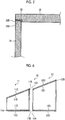
- Fig. 2 is a perspective diagram showing an appearance of the combustor.
- the combustor 7 includes a combustor body 10 and a fuel reforming mechanism 20 which is disposed to be adjacent to the combustor body 10. Both the combustor body 10 and the fuel reforming mechanism 20 are formed in a tubular shape with a ceramic-based composite material (Ceramic Matrix Composites: hereinafter referred to as CMC).
- CMC is a material improved in strength by combining inorganic particles, metal particles, whiskers, short fibers, long fibers, or the like with ceramics.
- CMC has a smaller specific gravity and higher heat resistance than a nickel base superalloy, and thus, is suitable for a material of the combustor 7.
- CMC is roughly divided into an oxide based CMC (for example, Al 2 O 3 (aluminum oxide)) and a non-oxide based CMC (for example, SiC (silicon carbide)), and in the present embodiment, CMC in which SiC fibers are compounded into non-oxide based SiC ceramics is used.
- oxide based CMC for example, Al 2 O 3 (aluminum oxide)
- non-oxide based CMC for example, SiC (silicon carbide)
- the combustor 7 is long (has several meters) in flow directions of a fuel gas and air, and thus, it is necessary to join the manufactured parts to each other in order to form a large-sized apparatus such as the combustor 7.
- the combustor body 10 is formed by joining a plurality of (three in the present embodiment) tubular bodies 11, 12, and 13 formed in a tubular shape in a longitudinal direction (the flow direction of each of the fuel gas and the air).
- the fuel reforming mechanism 20 is formed by joining a plurality (three in the present embodiment) of tubular bodies 21, 22, and 23 whose openings are arranged side by side in the longitudinal direction.
- the present embodiment the case where each of the combustor body 10 and the fuel reforming mechanism 20 is formed by joining three tubular bodies to each other is described.
- the present invention is not limited to this.
- a combustion chamber 14 in which the fuel gas is combusted is formed in inner spaces of the tubular bodies 11, 12, and 13, and an opening area (a length in a vertical direction in Fig. 2 ) of the combustion chamber 14 increases from an inlet end 10A of the combustor body 10 toward an outlet end 10B. Accordingly, the high-temperature and high-pressure gas combusted in the combustion chamber 14 is expanded toward the outlet end 10B and is supplied to the turbine 9.
- the tubular bodies 11, 12, and 13 of the combustor body 10 are joined to each other by joint sections 15 and 15.
- the fuel reforming mechanism 20 includes a plurality of (five in the present embodiment) fuel channels 24 which are formed side by side in the tubular bodies 21, 22, and 23.
- the fuel channels 24 configure a portion of the fuel supply path 6, and when the liquid fuel passes through the fuel channel 24, the liquid fuel is heated by the combustor body 10 so as to be reformed.
- the fuel reforming mechanism 20 is disposed below the combustor body 10.
- the fuel reforming mechanism 20 may be disposed in an internal space of the combustor body 10.
- the tubular bodies 21, 22, and 23 are joined to each other by joint sections 25 and 25.
- Fig. 3 is a sectional view showing a state before plate materials configuring a tubular body are joined to each other.
- Fig. 4 is a sectional view showing a joined state of the plate materials configuring the tubular body.
- Fig. 5 is a partially enlarged sectional view of the joined state.
- the tubular body 11 is described as an example. However, each of the tubular bodies 12 and 13 has the same configuration.
- the tubular body 11 is formed by joining four plate materials such as a bottom plate 31, a top plate 32, a right plate 33, and a left plate 34 to each other.
- Each plate material of the bottom plate 31, the top plate 32, the right plate 33, and the left plate 34 is formed of a non-oxide based (SiC based) CMC.
- the bottom plate (one plate material) 31 includes recessed sections 31B and 31B recessed from an inner surface 31A on both end portions of the inner surface (plate surface) 31A facing the top plate 32.
- the recessed sections 31B and 31B extend in a depth direction of the bottom plate 31, and lower end surfaces 33A and 34A of the right plate (other plate materials) 33 and the left plate (other plate materials) 34 are fitted to the recessed sections 31B and 31B.
- the top plate (one plate material) 32 includes recessed sections 32B and 32B recessed from an inner surface 32A on both end portions of the inner surface (plate surface) 32A facing the bottom plate 31.
- the recessed sections 31B and 31B extend in a depth direction of the top plate 32, and upper end surfaces 33B and 34B of the right plate (other plate materials) 33 and the left plate (other plate materials) 34 are fitted to the recessed sections 32B and 32B.
- the recessed section 32B provided on the inner surface 32A of the top plate 32 and the upper end surface 34B of the left plate 34 are joined to each other via an intermediate material 35.
- This intermediate material 35 is used for joining in CMC, and molten Si, a brazing material (glass, silicon, metal base), and ceramic precursor can be used.
- the intermediate material 35 is provided not only on the upper left side but also at all four locations shown in Fig. 5 . According to this configuration, four plate materials are joined to each other, and thus, it is possible to form the tubular bodies 11 to 13 having high load resistance (joining strength).
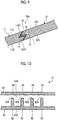
- Fig. 6 is a sectional view showing a state before the tubular bodies are joined to each other.
- Fig. 7 is a sectional view showing a joined state of the tubular bodies.
- Fig. 8 is a partially enlarged sectional view of a joint section.
- the joint section 15 between the tubular body 11 and the tubular body 12 is described as an example.
- the joint section 15 between the tubular body 12 and the tubular body 13 has a similar configuration. As shown in Figs.
- end surfaces 11B of the tubular body 11 and end surfaces 12A of the tubular body 12 abut each other, and thus, the tubular body 11 and the tubular body 12 are joined to each other.
- the end surface 11B of the tubular body 11 and the end surface 12A of the tubular body 12 are joined to each other via an intermediate material 16.
- the intermediate material 16 has a configuration similar to that of the above-described intermediate material 35.
- the combustor body 10 is formed such that the opening area (the length in the vertical direction) increases from the inlet end 10A toward the outlet end 10B. Accordingly, similarly to the combustor body 10, in each of the tubular bodies 11 and 12, an opening area of each tubular body increases from an inlet end thereof toward an outlet end thereof. That is, the opening area in the joint section 15 is the same for both the tubular bodies 11 and 12, and in a state where the joint section 15 is interposed between the tubular bodies 11 and 12, in the tubular body (first tubular body) 11, the opening area decreases toward the inlet end side to be smaller than the opening area in the joint section 15 (outlet end).
- the opening area increases toward the outlet end side to be larger than the opening area in the joint section 15.
- the outlet end surface 11B of the tubular body 11 is inclined to protrude from an inner surface 11D of the tubular body 11 toward an outer surface 11C thereof, and the inlet end surface 12A of the tubular body 12 is inclined to protrude from an outer surface 12C of the tubular body 12 toward an inner surface 12D thereof.
- each of the end surfaces 11B and 12A of the tubular bodies 11 and 12 are formed to be inclined, and thus, a joint distance (area) between the end surfaces 11B and 12A can be largely secured, and it is possible to prevent the tubular bodies 11 and 12 from being shifted in a radial direction (a direction orthogonal to flow directions of the fuel gas and the air). Accordingly, it is possible to increase the load resistance (joining strength) in the joint section 15 by a simple structure.
- the end surface 12A of the tubular body 12 having a large opening area enters the tubular body 11 having a small opening area, and thus, the end surface 12A is joined to the end surface 11B of the tubular body 11.
- each of the end surfaces 11B and 12A of the tubular bodies 11 and 12 is inclined at a predetermined inclination angle ⁇ with respect to a normal line on each of the inner surfaces 11D and 12D of the tubular bodies 11 and 12.
- the inclination angle ⁇ influences the load resistance (joining strength) in the joint section 15, and in the present embodiment, it is preferable that the inclination angle ⁇ is set to 10° to 60°.
- the inclination angle ⁇ is set to 10° to 60°.
- an outlet end surface 12B of the tubular body 12 is inclined to protrude from the inner surface 12D of the tubular body 12 toward the outer surface 12C and is joined to an inlet end surface (not shown) of the tubular body 13 which is similarly formed to the inlet end surface 12A of the tubular body 12.
- the inlet end surface 11A of the tubular body 11 is not joined to the tubular body and thus, is a flat surface.
- Fig. 9 is a partially enlarged sectional view of a joint section according to a modification example.
- the above-described joint section 15 is configured such that each of the end surfaces 11B and 12A of the tubular bodies 11 and 12 is uniformly inclined.
- a joint section 15A according to the modification example includes step sections 17 and 18 in which inclined end surfaces 11B1 and 12A1 of the tubular bodies 11 and 12 partially protrude and are interlocked with each other.
- the tubular body 11 includes a step section 17 in which the inner surface 11D side of the end surface 11B1 protrudes
- the tubular body 12 includes a step section 18 in which the outer surface 12C side of the end surface 12A1 protrudes.
- the step sections 17 and 18 are formed to have shapes and sizes to be interlocked with each other, and the end surfaces 11B1 and 12A1 are joined to each other via the intermediate material 16.
- each of the end surfaces 11B1 and 12A1 of the tubular bodies 11 and 12 is inclined at a predetermined inclination angle ⁇ with respect to a normal line on each of the inner surfaces 11D and 12D of the tubular bodies 11 and 12, and it is preferable that the inclination angle ⁇ is set to 10° to 60°.
- the joint section 15A includes the step sections 17 and 18 in which inclined end surfaces 11B1 and 12A1 of the tubular bodies 11 and 12 partially protrude and are interlocked with each other, the step sections 17 and 18 are firmly interlocked with each other, and thus, it is possible to further increase the load resistance (joining strength) in the joint section 15A.
- the fuel reforming mechanism 20 is formed by joining the tubular bodies 21, 22, and 23 having the plurality of fuel channels 24 formed side by side by the joint sections 25 and 25 ( Fig. 2 ).
- Fig. 10 is a sectional view showing a state before plate materials configuring the tubular bodies of the fuel reforming mechanism are joined to each other.
- Fig. 11 is a sectional view showing a joined state of the tubular bodies of the fuel reforming mechanism.
- the tubular body 21 is described as an example.
- each of the tubular bodies 22 and 23 has the same configuration. As shown in Fig.
- the tubular body 21 includes a bottom plate 41, a plurality of (four in the drawing) partition plates 42 which uprightly stands on an inner surface 41A of the bottom plate 41, and a top plate 43 which are joined to upper end surfaces 42A of the partition plates 42.
- the bottom plate 41, the partition plates 42, and the top plate 43 are formed of a non-oxide based (SiC based) CMC.
- Each of the partition plates 42 is a member which partitions a space in the tubular body 21, and extends in the depth direction of the bottom plate 41 by the same length as the bottom plate 41. As shown in Fig. 11 , the spaces portioned by the partition plates 42 configure the fuel channels 24.
- the partition plates 42 are integrally formed with the bottom plate 41. However, the partition plates 42 may be joined to the inner surface 41A of the bottom plate 41.
- the top plate (one plate material) 43 includes recessed sections 44 which are flatly recessed from an inner surface 43A at positions corresponding to the partition plates 42 of the inner surface (plate surface) 43A facing the bottom plate 41.
- Each of the recessed sections 44 is formed in a groove shape which extends in the depth direction of the top plate 43, and the upper flat end surface 42A of each partition plate 42 is fitted to the recessed section 44.
- the recessed sections 44 provided on the inner surface 43A of the top plate 43 and the upper end surfaces 42A of the partition plates 42 are joined to each other via intermediate materials. According to this configuration, the partition plates 42 provided on the bottom plate 41 and the top plate 43 are joined to each other, and thus, it is possible to form the tubular bodies 21 to 23 having high load resistance (joining strength).
- Fig. 12 is a sectional view showing a state before plate materials configuring tubular bodies of a fuel reforming mechanism according to a modification example are joined to each other
- Fig. 13 is a sectional view showing a joined state of the plate materials configuring the tubular bodies.
- the end surface 42A of each of the partition plate 42 is formed as a flat surface and the shape of the recessed section 44 is flatly recessed from the inner surface 43A of the top plate 43 in accordance with the end surface 42A.
- the present invention is not limited to this. For example, as shown in Figs.
- an end surface 42A1 of each partition plate 42 may be formed in an inclined surface and a shape of a recessed section 44A is formed in an inclined groove shape to be inclined from the inner surface 43A of the top plate 43 in accordance with the end surface 42A1.
- the tubular body 21A may be configured to include step sections in which the inclined end surface 42A1 of each partition plate 42 and a bottom surface of the inclined recessed section 44A partially protrude and are interlocked with each other. According to the configurations, the inclined end surfaces and the step sections are firmly interlocked with each other, and thus, it is possible to form the tubular body 21A having higher load resistance (joining strength).
- the end surface of the tubular body 21 is inclined to protrude from the inner surface of the tubular body 21 toward the outer surface thereof
- the end surface of the tubular body 22 is inclined to protrude from the outer surface of the tubular body 22 toward the inner surface thereof, and thus, it is possible to prevent the tubular bodies 21 and 22 from being shifted in the radial direction (a direction orthogonal to flow directions of the fuel gas and the air). Accordingly, it is possible to increase the load resistance (joining strength) in the joint section 25 by a simple structure.
- the joint section 25 by which the tubular body 22 and the tubular body 23 are joined to each other is similar to the joint section 25 by which the tubular body 21 and the tubular body 22 are joined to each other.
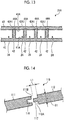
- Fig. 14 is a partially enlarged sectional view showing a state of a joint section according to the second embodiment before joining is performed
- Fig. 15 is a partially enlarged sectional view of the joined joint section.
- Figs. 14 and 15 correspond to Fig. 8 , and show a configuration of a joint section 115 in which an end surface 111B of a tubular body 111 and an end surface 112A of a tubular body 112 configuring the combustor body 10 abut each other, and thus, the tubular body 111 and the tubular body 112 are joined to each other.
- the joint section 115 in order to increase the load resistance (joining strength) in the joint section 115, includes a groove section 116 which extends in a circumferential direction on the end surface 111B of the tubular body (one tubular body) 111 and a fitting piece 117 which is fitted to the groove section 116 and protrudes from an end surface 112A of the tubular body (the other tubular body) 112.
- the intermediate material 16 is disposed between the end surface 111B and the end surface 112A, and the end surface 111B and the end surface 112A are joined to each other via the intermediate material 16.
- a length L1 of the fitting piece 117 protruding from the end surface 112A of the tubular body 112 and a thickness D1 of the plate material of the tubular body 112 influence the load resistance (joining strength) in the joint section 115, and in the present embodiment, it is preferable that a ratio of L1/D1 is set to 0.3 to 2.
- the joint section 115 in order to increase the load resistance (joining strength) in the joint section 115, includes the groove section 116 which extends in the circumferential direction on the end surface 111B of the tubular body 111 and the fitting piece 117 which is fitted to the groove section 116 and protrudes from the end surface 112A of the tubular body 112. Accordingly, it is possible to largely secure a joint distance (area) between the end surfaces 111B and 112A and it is possible to improve toughness of the joint section 115. Accordingly, it is possible to increase the load resistance (joining strength) in the joint section 115 by a simple structure.
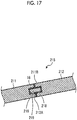
- Fig. 16 is a partially enlarged sectional view showing a state of a joint section according to the third embodiment before joining is performed
- Fig. 17 is a partially enlarged sectional view of the joined joint section.
- Figs. 16 and 17 correspond to Fig. 8 , and show a configuration of a joint section 215 in which an end surface 211B of a tubular body 211 and an end surface 212A of a tubular body 212 configuring the combustor body 10 abut each other, and thus, the tubular body 211 and the tubular body 212 are joined to each other.
- the joint section 215 in order to increase the load resistance (joining strength) in the joint section 215, includes a groove section 216 which extends in a circumferential direction on the end surface 211B of the tubular body (one tubular body) 211, a groove section 218 which faces the groove section 216 and extends in the circumferential direction on the end surface 212A of the tubular body (the other tubular body) 212, and a fitting piece 219 which is fitted to both groove sections 216 and 218.
- the intermediate material 16 is disposed between the end surface 211B and the end surface 212A, and the end surface 211B and the end surface 212A are joined to each other via the intermediate material 16.
- a length L2 of the fitting piece 219 which is fitted to both groove sections 216 and 218 and a thickness D2 of each of the plate materials of the tubular bodies 211 and 212 influence the load resistance (joining strength) in the joint section 215, and in the present embodiment, it is preferable that a ratio of L2/D2 is set to 0.3 to 2.
- the joint section 215 in order to increase the load resistance (joining strength) in the joint section 215, includes the groove section 216 which extends in the circumferential direction on the end surface 211B of the tubular body 211, the groove section 218 which faces the groove section 216 and extends in the circumferential direction on the end surface 212A of the tubular body (the other tubular body) 212, and the fitting piece 219 which is fitted to both groove sections 216 and 218. Accordingly, it is possible to largely secure a joint distance (area) between the end surfaces 211B and 212A and it is possible to improve toughness of the joint section 215. Accordingly, it is possible to increase the load resistance (joining strength) in the joint section 215 by a simple structure.
- the jet engine 1 is described as an example of a combustion apparatus having the combustor 7.
- the present invention is not limited to this, and the present invention can be used in an industrial gas turbine which rotates a turbine and drives an axis center using a high-temperature combustion gas supplied from the combustor 7.
- each of the joint sections 115 and 215 is applied to the joint section 25 of the fuel reforming mechanism 20.
- the joint sections 115 and 215 are respectively configured to include the fitting pieces 117 and 219 each having one stage.
- the fitting pieces 117 and 219 each having a plurality of stages may be configured.
Landscapes
- Engineering & Computer Science (AREA)
- General Engineering & Computer Science (AREA)
- Chemical & Material Sciences (AREA)
- Mechanical Engineering (AREA)
- Combustion & Propulsion (AREA)
- Ceramic Engineering (AREA)
- Materials Engineering (AREA)
- Structural Engineering (AREA)
- Organic Chemistry (AREA)
- Ceramic Products (AREA)
- Standing Axle, Rod, Or Tube Structures Coupled By Welding, Adhesion, Or Deposition (AREA)
- Mutual Connection Of Rods And Tubes (AREA)
Applications Claiming Priority (2)
| Application Number | Priority Date | Filing Date | Title |
|---|---|---|---|
| JP2016026815A JP6700836B2 (ja) | 2016-02-16 | 2016-02-16 | 接合構造、燃焼器、及び、燃焼装置 |
| PCT/JP2016/084068 WO2017141510A1 (ja) | 2016-02-16 | 2016-11-17 | 接合構造、燃焼器、及び、燃焼装置 |
Publications (2)
| Publication Number | Publication Date |
|---|---|
| EP3401295A1 true EP3401295A1 (de) | 2018-11-14 |
| EP3401295A4 EP3401295A4 (de) | 2018-12-26 |
Family
ID=59625756
Family Applications (1)
| Application Number | Title | Priority Date | Filing Date |
|---|---|---|---|
| EP16890647.7A Withdrawn EP3401295A4 (de) | 2016-02-16 | 2016-11-17 | Verbundene struktur, brennkammer und verbrennungsvorrichtung |
Country Status (5)
| Country | Link |
|---|---|
| US (1) | US20190041061A1 (de) |
| EP (1) | EP3401295A4 (de) |
| JP (1) | JP6700836B2 (de) |
| AU (1) | AU2016393065A1 (de) |
| WO (1) | WO2017141510A1 (de) |
Families Citing this family (2)
| Publication number | Priority date | Publication date | Assignee | Title |
|---|---|---|---|---|
| US11359505B2 (en) * | 2019-05-04 | 2022-06-14 | Raytheon Technologies Corporation | Nesting CMC components |
| JP7543168B2 (ja) * | 2021-02-24 | 2024-09-02 | 株式会社Subaru | 接着継手の製造方法 |
Family Cites Families (19)
| Publication number | Priority date | Publication date | Assignee | Title |
|---|---|---|---|---|
| JPS5233728B2 (de) * | 1973-12-25 | 1977-08-30 | ||
| JPS6065960A (ja) * | 1983-09-21 | 1985-04-15 | Shin Meiwa Ind Co Ltd | メカニカルシ−ル |
| DE3436831A1 (de) * | 1984-10-06 | 1986-09-04 | Didier-Werke Ag, 6200 Wiesbaden | Verfahren und verbindungselement zur verbindung keramischer teile |
| JPS6369769A (ja) * | 1986-09-10 | 1988-03-29 | 株式会社東芝 | セラミツクス接合体 |
| US4783229A (en) * | 1987-04-06 | 1988-11-08 | Gte Products Corporation | Ceramic tube |
| JP3064113B2 (ja) * | 1992-08-14 | 2000-07-12 | 三菱重工業株式会社 | ZrO2 セラミックスの接合方法 |
| JP4666791B2 (ja) * | 2001-02-27 | 2011-04-06 | 京セラ株式会社 | 接合体及びその製造方法 |
| JP2002263422A (ja) * | 2001-03-05 | 2002-09-17 | Mitsui Eng & Shipbuild Co Ltd | セラミックフィルタの接続方法 |
| JP5498191B2 (ja) * | 2009-02-16 | 2014-05-21 | 株式会社東芝 | 水素電力貯蔵システムおよび水素電力貯蔵方法 |
| JP5768101B2 (ja) * | 2009-02-16 | 2015-08-26 | 株式会社東芝 | セラミックス接合用材料とセラミックス複合部材の製造方法 |
| JP5260402B2 (ja) * | 2009-04-30 | 2013-08-14 | 三菱重工業株式会社 | 板状体の製造方法、板状体、ガスタービン燃焼器およびガスタービン |
| JP5959170B2 (ja) * | 2011-09-05 | 2016-08-02 | 三井金属鉱業株式会社 | セラミックス接合体及びその製造方法 |
| TWI445852B (zh) * | 2012-01-20 | 2014-07-21 | Sun Power Silicon Co Ltd | A graphite nozzle for refining polysilicon cycle vacuum equipment |
| JP2013213427A (ja) * | 2012-04-02 | 2013-10-17 | Toshiba Corp | 中空ノズルおよびその製造方法 |
| US9702490B2 (en) * | 2013-04-30 | 2017-07-11 | Corning Incorporated | Sealing method for silicon carbide parts used at high temperatures |
| US10137537B2 (en) * | 2014-03-13 | 2018-11-27 | Frederick M. Mako | System and method for producing chemicals at high temperature |
| US10683870B2 (en) * | 2015-03-24 | 2020-06-16 | Mitsubishi Heavy Industries Engine & Turbocharger, Ltd. | Impeller cover, rotary machine, and impeller cover manufacturing method |
| CA2925588A1 (en) * | 2015-04-29 | 2016-10-29 | Rolls-Royce Corporation | Brazed blade track for a gas turbine engine |
| DE102015215207A1 (de) * | 2015-08-10 | 2017-02-16 | Siemens Aktiengesellschaft | Brennkammer für eine Gasturbine und Hitzeschildelement zum Auskleiden einer derartigen Brennkammer |
-
2016
- 2016-02-16 JP JP2016026815A patent/JP6700836B2/ja active Active
- 2016-11-17 WO PCT/JP2016/084068 patent/WO2017141510A1/ja not_active Ceased
- 2016-11-17 EP EP16890647.7A patent/EP3401295A4/de not_active Withdrawn
- 2016-11-17 AU AU2016393065A patent/AU2016393065A1/en not_active Abandoned
- 2016-11-17 US US16/076,531 patent/US20190041061A1/en not_active Abandoned
Also Published As
| Publication number | Publication date |
|---|---|
| US20190041061A1 (en) | 2019-02-07 |
| JP6700836B2 (ja) | 2020-05-27 |
| EP3401295A4 (de) | 2018-12-26 |
| AU2016393065A1 (en) | 2018-08-30 |
| JP2017145159A (ja) | 2017-08-24 |
| WO2017141510A1 (ja) | 2017-08-24 |
Similar Documents
| Publication | Publication Date | Title |
|---|---|---|
| US11702948B2 (en) | CMC shroud segment with interlocking mechanical joints and fabrication | |
| EP2538141B1 (de) | Umkehrbrennkammer | |
| US10612402B2 (en) | Method of assembly of bi-cast turbine vane | |
| US11466580B2 (en) | CMC nozzle with interlocking mechanical joint and fabrication | |
| US7785076B2 (en) | Refractory component with ceramic matrix composite skeleton | |
| US20100150703A1 (en) | Stacked laminate bolted ring segment | |
| US20120308843A1 (en) | Method of manufacturing a hot-gas component with a cooling channel and a hot-gas component thereof | |
| US9909430B2 (en) | Turbine disk assembly including seperable platforms for blade attachment | |
| CN107917439B (zh) | 燃烧器后框架冷却 | |
| CN105697193A (zh) | Cmc氧化物-氧化物混合器设计 | |
| US20190145270A1 (en) | Cmc component and fabrication using mechanical joints | |
| EP3401295A1 (de) | Verbundene struktur, brennkammer und verbrennungsvorrichtung | |
| US10662786B2 (en) | CMC articles having small complex features for advanced film cooling | |
| CN103032104A (zh) | 用于涡轮系统的翼型件 | |
| CN107143382A (zh) | 用于先进膜冷却的具有小复杂特征的cmc制品 | |
| EP2673475B1 (de) | Modulares turbinenprofil mit einem verbindungsmechanismus und verfahren zur verzahnung | |
| EP3572625A1 (de) | Verbindung für ein deckband aus keramik | |
| US20200025018A1 (en) | Module for a turbomachine | |
| US11261741B2 (en) | Ceramic airfoil trailing end configuration | |
| US9915428B2 (en) | Cylinder of combustor, method of manufacturing of cylinder of combustor, and pressure vessel | |
| US11506383B2 (en) | Combustor liner and method of operating same | |
| US20210332705A1 (en) | Airfoil with cmc liner and multi-piece monolithic ceramic shell | |
| Singh | Integration Science and Technology of Silicon-Based Ceramics and Composites: Technical Challenges and Opportunities | |
| Halbig et al. | Joining and Integration of Silicon Carbide for Turbine Engine Applications |
Legal Events
| Date | Code | Title | Description |
|---|---|---|---|
| STAA | Information on the status of an ep patent application or granted ep patent |
Free format text: STATUS: THE INTERNATIONAL PUBLICATION HAS BEEN MADE |
|
| PUAI | Public reference made under article 153(3) epc to a published international application that has entered the european phase |
Free format text: ORIGINAL CODE: 0009012 |
|
| STAA | Information on the status of an ep patent application or granted ep patent |
Free format text: STATUS: REQUEST FOR EXAMINATION WAS MADE |
|
| 17P | Request for examination filed |
Effective date: 20180806 |
|
| AK | Designated contracting states |
Kind code of ref document: A1 Designated state(s): AL AT BE BG CH CY CZ DE DK EE ES FI FR GB GR HR HU IE IS IT LI LT LU LV MC MK MT NL NO PL PT RO RS SE SI SK SM TR |
|
| AX | Request for extension of the european patent |
Extension state: BA ME |
|
| A4 | Supplementary search report drawn up and despatched |
Effective date: 20181128 |
|
| RIC1 | Information provided on ipc code assigned before grant |
Ipc: F23R 3/42 20060101ALI20181123BHEP Ipc: F16L 49/00 20060101ALI20181123BHEP Ipc: F16B 7/00 20060101ALI20181123BHEP Ipc: F01D 25/00 20060101ALI20181123BHEP Ipc: C04B 37/00 20060101AFI20181123BHEP Ipc: F16L 23/16 20060101ALI20181123BHEP Ipc: F23M 5/00 20060101ALI20181123BHEP Ipc: F16B 11/00 20060101ALI20181123BHEP Ipc: F16L 13/10 20060101ALI20181123BHEP Ipc: F16L 13/08 20060101ALI20181123BHEP Ipc: F02C 7/00 20060101ALI20181123BHEP |
|
| DAV | Request for validation of the european patent (deleted) | ||
| DAX | Request for extension of the european patent (deleted) | ||
| STAA | Information on the status of an ep patent application or granted ep patent |
Free format text: STATUS: THE APPLICATION HAS BEEN WITHDRAWN |
|
| 18W | Application withdrawn |
Effective date: 20190924 |