EP3401476B1 - Vorrichtung zur bewegung eines an einem möbelkorpus eines möbels aufgenommenen möbelteils - Google Patents
Vorrichtung zur bewegung eines an einem möbelkorpus eines möbels aufgenommenen möbelteils Download PDFInfo
- Publication number
- EP3401476B1 EP3401476B1 EP18171001.3A EP18171001A EP3401476B1 EP 3401476 B1 EP3401476 B1 EP 3401476B1 EP 18171001 A EP18171001 A EP 18171001A EP 3401476 B1 EP3401476 B1 EP 3401476B1
- Authority
- EP
- European Patent Office
- Prior art keywords
- furniture
- lever
- articulated lever
- articulated
- held
- Prior art date
- Legal status (The legal status is an assumption and is not a legal conclusion. Google has not performed a legal analysis and makes no representation as to the accuracy of the status listed.)
- Active
Links
Images



Classifications
-
- E—FIXED CONSTRUCTIONS
- E05—LOCKS; KEYS; WINDOW OR DOOR FITTINGS; SAFES
- E05D—HINGES OR SUSPENSION DEVICES FOR DOORS, WINDOWS OR WINGS
- E05D3/00—Hinges with pins
- E05D3/06—Hinges with pins with two or more pins
- E05D3/16—Hinges with pins with two or more pins with seven parallel pins and four arms
-
- E—FIXED CONSTRUCTIONS
- E05—LOCKS; KEYS; WINDOW OR DOOR FITTINGS; SAFES
- E05D—HINGES OR SUSPENSION DEVICES FOR DOORS, WINDOWS OR WINGS
- E05D15/00—Suspension arrangements for wings
- E05D15/40—Suspension arrangements for wings supported on arms movable in vertical planes
- E05D15/401—Suspension arrangements for wings supported on arms movable in vertical planes specially adapted for overhead wings
-
- E—FIXED CONSTRUCTIONS
- E05—LOCKS; KEYS; WINDOW OR DOOR FITTINGS; SAFES
- E05D—HINGES OR SUSPENSION DEVICES FOR DOORS, WINDOWS OR WINGS
- E05D7/00—Hinges or pivots of special construction
- E05D7/04—Hinges adjustable relative to the wing or the frame
- E05D7/0415—Hinges adjustable relative to the wing or the frame with adjusting drive means
-
- E—FIXED CONSTRUCTIONS
- E05—LOCKS; KEYS; WINDOW OR DOOR FITTINGS; SAFES
- E05D—HINGES OR SUSPENSION DEVICES FOR DOORS, WINDOWS OR WINGS
- E05D7/00—Hinges or pivots of special construction
- E05D7/04—Hinges adjustable relative to the wing or the frame
- E05D7/0415—Hinges adjustable relative to the wing or the frame with adjusting drive means
- E05D7/0423—Screw-and-nut mechanisms
-
- E—FIXED CONSTRUCTIONS
- E05—LOCKS; KEYS; WINDOW OR DOOR FITTINGS; SAFES
- E05F—DEVICES FOR MOVING WINGS INTO OPEN OR CLOSED POSITION; CHECKS FOR WINGS; WING FITTINGS NOT OTHERWISE PROVIDED FOR, CONCERNED WITH THE FUNCTIONING OF THE WING
- E05F1/00—Closers or openers for wings, not otherwise provided for in this subclass
- E05F1/08—Closers or openers for wings, not otherwise provided for in this subclass spring-actuated, e.g. for horizontally sliding wings
- E05F1/10—Closers or openers for wings, not otherwise provided for in this subclass spring-actuated, e.g. for horizontally sliding wings for swinging wings, e.g. counterbalance
- E05F1/1041—Closers or openers for wings, not otherwise provided for in this subclass spring-actuated, e.g. for horizontally sliding wings for swinging wings, e.g. counterbalance with a coil spring perpendicular to the pivot axis
- E05F1/1066—Closers or openers for wings, not otherwise provided for in this subclass spring-actuated, e.g. for horizontally sliding wings for swinging wings, e.g. counterbalance with a coil spring perpendicular to the pivot axis with a traction spring
- E05F1/1075—Closers or openers for wings, not otherwise provided for in this subclass spring-actuated, e.g. for horizontally sliding wings for swinging wings, e.g. counterbalance with a coil spring perpendicular to the pivot axis with a traction spring for counterbalancing
-
- E—FIXED CONSTRUCTIONS
- E05—LOCKS; KEYS; WINDOW OR DOOR FITTINGS; SAFES
- E05D—HINGES OR SUSPENSION DEVICES FOR DOORS, WINDOWS OR WINGS
- E05D3/00—Hinges with pins
- E05D3/06—Hinges with pins with two or more pins
- E05D3/16—Hinges with pins with two or more pins with seven parallel pins and four arms
- E05D2003/163—Horizontal pivot-axis
-
- E—FIXED CONSTRUCTIONS
- E05—LOCKS; KEYS; WINDOW OR DOOR FITTINGS; SAFES
- E05D—HINGES OR SUSPENSION DEVICES FOR DOORS, WINDOWS OR WINGS
- E05D7/00—Hinges or pivots of special construction
- E05D7/12—Hinges or pivots of special construction to allow easy detachment of the hinge from the wing or the frame
- E05D7/123—Hinges or pivots of special construction to allow easy detachment of the hinge from the wing or the frame specially adapted for cabinets or furniture
-
- E—FIXED CONSTRUCTIONS
- E05—LOCKS; KEYS; WINDOW OR DOOR FITTINGS; SAFES
- E05Y—INDEXING SCHEME ASSOCIATED WITH SUBCLASSES E05D AND E05F, RELATING TO CONSTRUCTION ELEMENTS, ELECTRIC CONTROL, POWER SUPPLY, POWER SIGNAL OR TRANSMISSION, USER INTERFACES, MOUNTING OR COUPLING, DETAILS, ACCESSORIES, AUXILIARY OPERATIONS NOT OTHERWISE PROVIDED FOR, APPLICATION THEREOF
- E05Y2201/00—Constructional elements; Accessories therefor
- E05Y2201/10—Covers; Housings
-
- E—FIXED CONSTRUCTIONS
- E05—LOCKS; KEYS; WINDOW OR DOOR FITTINGS; SAFES
- E05Y—INDEXING SCHEME ASSOCIATED WITH SUBCLASSES E05D AND E05F, RELATING TO CONSTRUCTION ELEMENTS, ELECTRIC CONTROL, POWER SUPPLY, POWER SIGNAL OR TRANSMISSION, USER INTERFACES, MOUNTING OR COUPLING, DETAILS, ACCESSORIES, AUXILIARY OPERATIONS NOT OTHERWISE PROVIDED FOR, APPLICATION THEREOF
- E05Y2201/00—Constructional elements; Accessories therefor
- E05Y2201/20—Brakes; Disengaging means; Holders; Stops; Valves; Accessories therefor
- E05Y2201/25—Mechanical means for force or torque adjustment therefor
-
- E—FIXED CONSTRUCTIONS
- E05—LOCKS; KEYS; WINDOW OR DOOR FITTINGS; SAFES
- E05Y—INDEXING SCHEME ASSOCIATED WITH SUBCLASSES E05D AND E05F, RELATING TO CONSTRUCTION ELEMENTS, ELECTRIC CONTROL, POWER SUPPLY, POWER SIGNAL OR TRANSMISSION, USER INTERFACES, MOUNTING OR COUPLING, DETAILS, ACCESSORIES, AUXILIARY OPERATIONS NOT OTHERWISE PROVIDED FOR, APPLICATION THEREOF
- E05Y2600/00—Mounting or coupling arrangements for elements provided for in this subclass
- E05Y2600/40—Mounting location; Visibility of the elements
- E05Y2600/41—Concealed
-
- E—FIXED CONSTRUCTIONS
- E05—LOCKS; KEYS; WINDOW OR DOOR FITTINGS; SAFES
- E05Y—INDEXING SCHEME ASSOCIATED WITH SUBCLASSES E05D AND E05F, RELATING TO CONSTRUCTION ELEMENTS, ELECTRIC CONTROL, POWER SUPPLY, POWER SIGNAL OR TRANSMISSION, USER INTERFACES, MOUNTING OR COUPLING, DETAILS, ACCESSORIES, AUXILIARY OPERATIONS NOT OTHERWISE PROVIDED FOR, APPLICATION THEREOF
- E05Y2600/00—Mounting or coupling arrangements for elements provided for in this subclass
- E05Y2600/60—Mounting or coupling members; Accessories therefor
- E05Y2600/626—Plates or brackets
-
- E—FIXED CONSTRUCTIONS
- E05—LOCKS; KEYS; WINDOW OR DOOR FITTINGS; SAFES
- E05Y—INDEXING SCHEME ASSOCIATED WITH SUBCLASSES E05D AND E05F, RELATING TO CONSTRUCTION ELEMENTS, ELECTRIC CONTROL, POWER SUPPLY, POWER SIGNAL OR TRANSMISSION, USER INTERFACES, MOUNTING OR COUPLING, DETAILS, ACCESSORIES, AUXILIARY OPERATIONS NOT OTHERWISE PROVIDED FOR, APPLICATION THEREOF
- E05Y2900/00—Application of doors, windows, wings or fittings thereof
- E05Y2900/20—Application of doors, windows, wings or fittings thereof for furniture, e.g. cabinets
Definitions
- guide means such as furniture hinges or flap fittings are known in order to be able to move a furniture part relative to a furniture body.
- the guide means have to meet different requirements; in particular, the inside of the furniture body or the movable furniture part should be made accessible with the movement guide in order to be able to accommodate objects therein or remove them therefrom. Furthermore, the guide means must be accommodated in a space-saving manner.
- the object of the present invention is to improve a device for moving a furniture part accommodated on a furniture body of a piece of furniture, in particular with regard to a compact, comparatively less bulky accommodation of the device on the piece of furniture or to reduce the material costs of the device.
- the invention is based on a device for moving a furniture part accommodated on a furniture body of a piece of furniture, in particular the invention is based on a device for moving a movable furniture part, e.g. a flap or a furniture flap, of a piece of furniture, the device having guide means which when the device is mounted on the piece of furniture, the furniture part can be moved from a closed position into an open position relative to the furniture body and back, with the furniture part in the closed position assuming a position that is moved up to a maximum of a front side of the furniture body.
- a movable furniture part e.g. a flap or a furniture flap
- the device is designed, for example, as a swivel fitting or flap fitting for e.g. an upper flap of a piece of furniture.
- the furniture is available, for example, as a wall cabinet.
- the core of the invention is seen in the fact that the device has a housing on which the guide means are movably mounted, with the guide means being designed as an articulated lever, with a first and a second articulated lever being present, with the first and the second articulated lever being articulated with one another are connected, wherein the first toggle is sandwiched with at least two lever arms, so that the second toggle is movably received between the two lever arms of the first toggle.
- the device is designed to be comparatively space-saving. Due to the sandwich-like arrangement, the articulated levers or the lever arms of the articulated levers of the device are comparatively slim. the The sandwich-like design of at least one articulated lever also enables the articulated lever to apply a comparatively central force to the housing. As a result, the device is designed to be comparatively stable.
- the housing of the device can advantageously be arranged on an inside of an outer wall of the furniture body.
- the housing of the device is preferably present in such a way that it can be inserted into a recess in the outer wall.
- an outside of the housing which in the arranged state on the furniture body faces an interior of the furniture body, is flush and/or flush with the inside of the outer wall or, for example, protrudes comparatively slightly.
- the second articulated lever has, for example, a single lever arm. However, it is also conceivable that the second articulated lever has two, in particular exactly two, lever arms. If the second articulated lever has two lever arms, the two lever arms can, for example, rest without a gap, e.g. congruently, be present, in particular be connected to one another. For example, the two lever arms of the second articulated lever are pressed and/or welded together.
- an articulated lever has two or more lever arms
- the lever arms are advantageously of the same type, in particular identical, for example of the same design.
- a lever arm is present twice in this case.
- several lever arms of an articulated lever are advantageously arranged offset parallel to one another, in particular spaced apart.
- the lever arms of an articulated lever in the arranged state on the device are congruent when viewed from the side.
- the two lever arms of the first articulated lever preferably enclose the second articulated lever, for example in the manner of a sandwich.
- the two lever arms of the first articulated lever advantageously enclose the lever arm or arms of the second articulated lever.
- the second articulated lever is arranged on the inside of the first articulated lever.
- a lever arm of an articulated lever and/or the articulated lever itself is L-shaped, for example.
- a lateral distance between the lever arms of an articulated lever is advantageously present in such a way that a user of the piece of furniture on which the device is arranged cannot pinch a finger.
- a lateral distance between the lever arms of an articulated lever and/or a lateral distance between several lever arms of different articulated levers is less than or equal to 6 mm.
- the first articulated lever is designed so that it can be arranged detachably on the assembly means of the device, with the assembly means being mountable on the furniture part.
- the mounting means include, for example, a mounting unit, which is designed, for example, as a mounting plate. In this way, a comparatively simple and quick, in particular easier, installation of the device on the piece of furniture is realized.
- the assembly unit is first mounted on the furniture part and the first articulated lever is arranged on the furniture body.
- the furniture part or the assembly unit is then detachably connected to the first articulated lever.
- the first articulated lever can be hung or clipped in on the assembly unit.
- the first articulated lever can be connected to the mounting unit by means of a screw connection and/or a bayonet-type connection is. It is also conceivable that the first articulated lever can be clamped onto the assembly unit.
- the guide means comprise a third articulated lever, the third articulated lever being designed in a sandwich-like manner with at least two lever arms, so that the second articulated lever is movably accommodated between two lever arms of the third articulated lever.
- the guide means comprise a fourth articulated lever, the fourth articulated lever being movably accommodated between the two lever arms of the third articulated lever.
- the fourth articulated lever is movably accommodated between the two lever arms of the first articulated lever.
- the guide means comprise a fifth articulated lever, the fifth articulated lever being designed in the manner of a sandwich, so that the fourth articulated lever is movably accommodated between two lever arms of the fifth articulated lever.
- the guide means comprise a sixth articulated lever, the sixth articulated lever being movably accommodated between the two lever arms of the fifth articulated lever.
- the guide means comprise a seventh articulated lever, with the seventh articulated lever being designed in the manner of a sandwich, so that the sixth articulated lever is movably accommodated between two lever arms of the seventh articulated lever.
- the thickness of an articulated lever is less than or equal to 6 mm.
- the thickness or width of an articulated lever is between 0.2 mm and 6 mm.
- the thickness of a toggle lever is 0.5mm, 0.6mm, 0.8mm, 1mm, 1.1mm, 1.2mm, 1.3mm, 1.4mm 1.5mm, 1.6mm, 1.7mm, 1, 8mm, 1.9mm, 2mm, 2.5mm, 3mm, 3.5mm, 4mm, 4.5mm or 5mm.
- a lever arm of an articulated lever advantageously has a thickness of less than or equal to 2 mm, for example a thickness in a range between 0.2 mm and 2 mm.
- a lever arm of an articulated lever has a thickness of 0.5mm, 0.6mm, 0.8mm, 1mm, 1.1mm, 1.2mm, 1.3mm, 1.4mm, 1.6mm, 1.7mm, 1.8mm or 1.9mm.
- a lever arm of an articulated lever has a thickness of 1.5 mm or 2 mm.
- lever arms of an articulated lever are spaced apart from one another by a distance of less than 6 mm in the direction of thickness or width.
- lever arms of two or more articulated levers, which are connected to one another in particular in an articulated manner have a spacing of less than 6 mm in the direction of thickness or width.
- the lever arms of two or more articulated levers, which are connected to one another in an articulated manner have a distance of between 0.2 mm and 6 mm or between 1 mm and 5 mm in the thickness or width direction, e.g.
- the thicknesses or the widths of the various articulated levers differ from one another.
- the thicknesses or widths of the lever arms of the various articulated levers differ from one another.
- the first, the third, the fifth and the seventh link lever have the same thickness or width.
- the second, fourth and sixth articulated lever to be of the same thickness or width are.
- all lever arms of all articulated levers are of the same thickness or width.
- an articulated lever or a lever arm of the articulated lever extends along a plane of extent, the articulated lever being movably mounted on the device, for example, in such a way that the articulated lever moves in the plane of extent when the device is in the arranged state on the piece of furniture during an opening or closing movement of the furniture part .
- a first plane of extension of an articulated lever and/or a plane of extension of a lever arm of the articulated lever and a second plane of extension of a further articulated lever and/or a second plane of extension of a lever arm of the further articulated lever are advantageously present parallel to one another.
- all extension planes of all articulated levers are aligned parallel to one another.
- the second, the fourth and the sixth articulated lever and/or a lever arm of the second, the fourth and the sixth articulated lever move in the same extension plane.
- the device has an energy storage device which acts on the guide means, with the energy storage device comprising a spring assembly consisting of several spring elements, in particular three or more spring elements, which are present next to one another.
- the energy storage device advantageously moves the furniture part from a closed position relative to the furniture body, e.g. from the closed position, into an open position relative to the furniture body.
- the spring assembly comprises three parallel coil springs next to one another in one plane.
- the spring assembly advantageously extends parallel to a plane of movement of an articulated lever, in particular parallel to all planes of movement of all articulated levers.
- the device preferably has setting means for setting a force, in particular a spring force of the energy accumulator.
- the force accumulator is connected to the sixth and/or the seventh articulated lever.
- the force accumulator is movably connected to the sixth and/or the seventh articulated lever.
- a first end of the force accumulator is movably mounted on the sixth and/or seventh articulated lever.
- the energy store is connected to the housing with a second end, which is spaced apart and opposite the first end.
- the second end of the force accumulator is, for example, movably fixed to the housing.
- the housing has a base body and a cover, with at least one articulated lever of the guide means being pivotably mounted on a bearing on the housing, with the bearing being held on two sides, in particular on both sides of the housing.
- the articulated lever is movably mounted on a bearing of the housing.
- the bearing is advantageously held on two sides both on the base body and on the cover of the housing.
- the third, the fifth and/or the seventh articulated lever is movably mounted on the housing, for example pivotably, in particular rotatably mounted.
- the device preferably comprises damping means for damping a closing movement of the guide means, in particular a closing movement of a furniture part arranged on the device.
- the damping means are designed and arranged on the housing in such a way that the damping means cause a closing movement of the articulated lever dampen, in particular the damping means act on a hinged lever during the closing movement of the hinged lever, in particular on a single hinged lever.
- FIG. 1 shows a perspective view of a piece of furniture or a wall cabinet 1 with a box-shaped furniture body 2 and a furniture part accommodated thereon, which is designed as a panel-like top flap 3 , which is shown in an open position relative to the furniture body 2 .
- the furniture body 2 comprises two opposite, upright side walls 4 and 5, which are connected to a bottom panel 6 and to a top panel 7 at the top.
- the furniture body 2 is closed by a rear wall 8 at the rear.
- a movement device is present, which is designed as an upper flap fitting 9 .
- the upper flap fitting 9 has a first fitting unit 10 on the side wall 4 and a second fitting unit 11 on the side wall 5, which are constructed in the same way but for the functionally correct arrangement on the respective side wall 4 or 5 in relation to the side.
- Each fitting unit 10 and 11 comprises a base unit 12, guide means 13 with articulated levers and a mounting unit in the form of a mounting plate 15a, 15b.
- the base unit 12 is connected to the mounting plate 15a, 15b via several articulated joint levers, which are present as pivot arms 14.1 to 14.7 of a pivot arm arrangement 14.
- the guide means 13 have an energy accumulator 16 adjustable with an adjustment unit 17 to support the opening movement of the upper flap 3 into the open position or open position and a damping device 18 for a damped closing movement of the upper flap 3 into the closed position or closed position.
- the base unit 12 is preferably formed from a sheet metal component and comprises a flat, flat or thin base plate 19 and a base plate 19 opposite flat thin cover plate 20, which only in the Figures 1 and 2 is shown.
- a Forehead section 21 is present, the outside of which is aligned transversely to the base plate 19 level.
- the relevant pivoting arms of the pivoting arm arrangement 14 reach through a rectangular recess 22 in the end section 21.
- the base plate 12 which has a square or rectangular base, for example, has four straight base plate edges 23 to 26, with the exemplary embodiment shown at the two adjacent base plate edges 25 and 26 each having a rectangle that is perpendicular to the plane of the base plate 19, for example - or strip-shaped wall section 27, 28 is present.
- the wall sections 27, 28 are, for example, identical in height, which is preferably a predetermined amount less than, for example, the thickness of the wall element of the piece of furniture or the side wall 4 of the upper cabinet 1 to which the base unit 12 of the fitting unit 10 is attached. If the side wall 4 has a usual thickness a of 16 millimeters (see 2 ), then a height of the base unit 12 is preferably 12 millimeters or less, for example.
- the base unit 12 can be sunk or inserted flush into a prepared material recess 31 if the material recess 31 has a depth of 12 millimeters.
- the residual bottom thickness of the material recess 31 is then accordingly 4 millimeters.
- the height of the base unit is also made up, for example, of the thickness of the base plate 19 and the thickness of the contact flange 29, 30. With an assumed sheet metal thickness of, for example, one millimeter and a height of the base unit 12 of 12 millimeters, the height of the wall section 27 or 28 is, for example, ten millimeters.
- contact flanges 29, 30 are present.
- the fitting unit 10 or the base unit 12 can be firmly attached to the side wall 4 with the contact flanges 29, 30 and fastening means such as screw means 40 engaging or passing through them, in particular fixed in position and without play.
- the base unit 12 used also contributes to the stabilization of the weakened side wall 4, 5 in the area of the material recess 31.
- a surface contact via the surface contact of the outside of the base unit 12 with the wall of the material recess 31 has an advantageous effect, which has a stabilizing effect.
- the attachment or adhesive effect can be improved or increased by means of adhesive, such as an adhesive layer, between the base unit 12 and the material recess 31 .
- Each wall section 27 and 28 is adjoined by a contact flange angled at right angles to it, i.e. contact flange 29 on wall section 27 and contact flange 30 on wall section 28.
- Contact flanges 29, 30 are also rectangular or strip-shaped, for example between 5 and 25 millimeters wide. preferably about 15 millimeters wide.
- the fastening means such as the screw means 40, reach through, e.g. prepared through-holes in the contact flanges 29, 30.
- the rectangular flat end section 21 is countersunk flush with a front, narrow end face 4b of the side wall 4.
- top base plate edge 24 is perpendicular to the plane of the base plate 19, for example, at right angles projecting wall portion 32 is provided, but without a contact flange, since the Base plate edge 24 connects to the top floor 7 on the underside.
- a screw 33 engages through an obliquely aligned passage opening in an angle element 34 and through an opening 35 in the wall section 32, so that the screw 33 can be screwed into the top panel 7 at an angle, with the base unit 12 being pushed upwards and is attracted to the side wall 4.
- the mounting plate 15a, 15b is also advantageously sunk into a corresponding material recess 36 in the top flap 3, preferably housed flush with the inside of the top flap 3.
- the fitting unit 10 or the base unit 12 can also be attached to the furniture body 2 without a material recess (see Fig. 8 ).
- screw means 37 reach through the cover plate 20 and the holes in the contact flanges 29 and 30 and through adapter means (not shown), which can be inserted between the underside of the contact flanges 29, 30 and the inside 4a of the side wall 4, with corresponding openings therein for reaching through the Screwing means 37, which can be screwed into the side wall 4 and extend beyond the adapter means.
- a further variant of an assembly unit 15a or 15b is also available, which is adapted, for example, to the special attachment position of the fitting unit 10 on the furniture body 2.
- FIG 10 shows the upper section of the upper cabinet 1 with the upper flap 3 open, the upper flap 3 being shown in partial section and the mounting plate 15a being shown in full. Accordingly, the mounting plate 15a is received in the matching material recess 36 almost completely countersunk.
- the mounting plate 15a is comparable in the basic form, for example, with the basic form of the base unit 12 and has a flat base plate 42, a wall section 43 projecting thereupon and a contact flange 44 projecting at an angle outwards on the wall section 43.
- An upper side 44a of the mounting plate 15a or the contact flange 44 and a lid-like, flat or thin cover 41 detachably attached to it protrude slightly beyond the inside 3a of the upper flap 3, for example.
- the material recess 36 includes a deeper main pocket 36a and a shallower side pocket 36b, in which the contact flange 44 of the mounting plate 15a is accommodated.
- Adjusting means 45 for adjusting the relative position between the swivel arm arrangement 14 and the mounting plate 15a are accommodated in the recessed area of the mounting plate 15a above the base plate 42 and within the height of the wall section 43 .
- the swivel arm 14.1 extends from the swivel arm arrangement 14 to the area of the mounting plate 15a.
- the adjustment means 45 of the mounting plate 15a include, for example, depth adjustment means 46 with an adjusting screw 47, for example, side adjustment means 48 with an eccentric 49, for example, and/or height adjustment means 50 with an adjusting screw, for example.
- the depth adjustment means 46 are used to adjust the relative position between the swivel arm arrangement 14 and the mounting plate 15a in the directions indicated by the double arrow P1.
- the lateral adjustment means 48 which are present as fixed bearings, are used to adjust the relative position between the swivel arm arrangement 14 and the mounting plate 15a in the directions according to the double arrow P2.
- the height adjustment means 50 are used to adjust the relative position between the swivel arm arrangement 14 and the mounting plate 15a in the direction indicated by the double arrow P3.
- quick-connecting means 52 are provided, which on the pivot arm arrangement 14 comprise a pivotable latching lever 53 and a pin 54 close to the latching lever 53 and another pin 55 spaced apart from the latching lever 53, the longitudinal axes of the pins 54, 55 being parallel to the pivot axis of the Locking lever 53 run.
- the quick-connection means 52 comprise a latching lug 56 and a latching hook 57, which are designed to be matched to the latching lever 53, the pin 54 and the pin 55.
- the pin 54 comes into a stop position in a notch of the locking hook 57 and, at the same time, the pin 55 comes into a notch in the locking hook 57 when the locking lever 53 is pivoted counterclockwise the locking lever 53 is manually pivoted clockwise according to P4, so that a lug of the locking lever 53 engages in a recess of the locking lug 56 and the fixed anchorage is set up.
- the disassembly is carried out by the reverse order of the steps that are necessary for assembly.
- FIG 13 shows a perspective exploded view of the upper flap fitting 9.
- the first pivoting arm 14.1 includes two pivoting levers 38a, 38b in which or between which a pivoting lever 39 of the second pivoting arm 14.2 in arranged state is pivotally mounted.
- Other pivoted levers 14.3-14.7 are arranged analogously.
- a pivoting lever 58 of the fourth pivoting arm 14.4 is advantageously pivotally mounted on the first, third and fifth pivoting arm 14.1, 14.2, 14.3.
- the second, the fourth and the sixth swivel arm 14.2, 14.4, 14.6 each comprise a single swivel lever 39, 58, 59.
- the swivel levers 39, 58, 59 are advantageously pivotably mounted in the arranged state in such a way that they move during an opening or closing movement of the Move upper flap 3 in a common plane of movement.
- the left-hand pivoting lever 38b or the right-hand pivoting lever 38a of the first, the third, the fifth and the seventh pivoting arm 14.1, 14.3, 14.5, 14.7 advantageously also move along a common plane of movement in the arranged state.
- the movement planes are advantageously aligned parallel to one another.
- the third, the fifth and the seventh swivel arm 14.3, 14.5, 14.7 is advantageously on a bearing 60-62 ( figure 3 ) movably mounted on both sides of the base unit 12, in particular on the base plate 19 and on the cover plate 20.
- adjusting means 13 means of guidance 46
Landscapes
- Engineering & Computer Science (AREA)
- Mechanical Engineering (AREA)
- Hinges (AREA)
- Drawers Of Furniture (AREA)
- Cabinets, Racks, Or The Like Of Rigid Construction (AREA)
Description
- Im Möbelbereich sind Führungsmittel wie Möbelscharniere oder Klappenbeschläge bekannt, um ein Möbelteil relativ zu einem Möbelkorpus bewegen zu können. Aus der
CN 104 775 701 B ist eine Vorrichtung gemäß dem Oberbegriff des Anspruchs 1 bekannt. - Die Führungsmittel müssen unterschiedlichen Anforderungen gerecht werden, insbesondere soll mit der Bewegungsführung ein Inneres des Möbelkorpus bzw. des bewegbaren Möbelteils zugänglich gemacht werden, um Gegenstände darin unterbringen oder daraus entnehmen zu können. Des Weiteren müssen die Führungsmittel platzsparend unterbringbar sein.
- Aufgabe der vorliegenden Erfindung ist es, eine Vorrichtung zur Bewegung eines an einem Möbelkorpus eines Möbels aufgenommenen Möbelteils zu verbessern, insbesondere im Hinblick auf eine kompakte, vergleichsweise wenig auftragende Unterbringung der Vorrichtung am Möbel bzw. einen Materialaufwand der Vorrichtung zu reduzieren.
- Diese Aufgabe wird durch die unabhängigen Ansprüche gelöst.
- In den abhängigen Ansprüchen sind vorteilhafte und zweckmäßige Weiterbildungen der Erfindung thematisiert.
- Die Erfindung geht von einer Vorrichtung zur Bewegung eines an einem Möbelkorpus eines Möbels aufgenommenen Möbelteils aus, insbesondere geht die Erfindung von einer Vorrichtung zur Bewegung eines bewegbaren Möbelteils, z.B. einer Klappe bzw. einer Möbelklappe, eines Möbels aus, wobei die Vorrichtung Führungsmittel aufweist, mit welchen bei montierter Vorrichtung am Möbel das Möbelteil aus einer Schließposition in eine Offenposition relativ zum Möbelkorpus und zurück bewegbar ist, wobei das Möbelteil in der Schließposition eine maximal an eine Frontseite des Möbelkorpus heranbewegte Position einnimmt.
- Die Vorrichtung ist beispielsweise als Schwenkbeschlag oder Klappenbeschlag für z.B. eine Oberklappe eines Möbels ausgebildet. Das Möbel ist beispielsweise als ein Hängeschrank vorhanden.
- Der Kern der Erfindung wird darin gesehen, dass die Vorrichtung ein Gehäuse aufweist, an welchem die Führungsmittel beweglich gelagert sind, wobei Führungsmittel als ein Gelenkhebel ausgebildet sind, wobei ein erster und ein zweiter Gelenkhebel vorhanden ist, wobei der erste und der zweite Gelenkhebel gelenkig miteinander verbunden sind, wobei der erste Gelenkhebel sandwichartig mit wenigstens zwei Hebelarmen ausgebildet ist, sodass der zweite Gelenkhebel zwischen den zwei Hebelarmen des ersten Gelenkhebels beweglich aufgenommen ist. Hierdurch ist die Vorrichtung vergleichsweise platzsparend ausgebildet. Durch die sandwichartige Anordnung sind die Gelenkhebel bzw. die Hebelarme der Gelenkhebel der Vorrichtung vergleichsweise schlank vorhanden. Die sandwichartige Ausgestaltung zumindest eines Gelenkhebels ermöglicht außerdem eine vergleichsweise zentrale Krafteinleitung des Gelenkhebels auf das Gehäuse. Hierdurch ist die Vorrichtung vergleichsweise stabil ausgebildet.
- Das Gehäuse der Vorrichtung ist vorteilhafterweise an eine Innenseite einer Außenwand des Möbelkorpus anordenbar. Bevorzugterweise ist das Gehäuse der Vorrichtung derart vorhanden, dass es in eine Aussparung der Außenwand einsetzbar ist. Vorteilhafterweise ist eine Außenseite des Gehäuses, welche im angeordneten Zustand am Möbelkorpus einem Innenraum des Möbelkorpus zugewandt ist bündig und/oder fluchtend zur Innenseite der Außenwand oder beispielsweise vergleichsweise gering überstehend vorhanden.
- Der zweite Gelenkhebel besitzt beispielsweise einen einzigen Hebelarm. Denkbar ist aber auch, dass der zweite Gelenkhebel zwei, insbesondere genau zwei, Hebelarme aufweist. Besitzt der zweite Gelenkhebel zwei Hebelarme, können die beiden Hebelarme beispielsweise abstandslos aneinander anliegend, z.B. deckungsgleich, vorhanden sein, insbesondere miteinander verbunden sein. Beispielsweise sind die beiden Hebelarme des zweiten Gelenkhebels miteinander verpresst und/oder verschweißt vorhanden.
- Besitzt ein Gelenkhebel zwei oder mehr Hebelarme, sind die Hebelarme vorteilhafterweise gleichartig, insbesondere identisch, beispielsweise denkungsgleich ausgebildet. Beispielsweise ist ein Hebelarm in diesem Fall doppelt vorhanden. Mehrere Hebelarme eines Gelenkhebels sind im angeordneten Zustand an der Vorrichtung vorteilhafterweise parallel versetzt zueinander angeordnet, insbesondere beabstandet vorhanden. Beispielsweise sind die Hebelarme eines Gelenkhebels im angeordneten Zustand an der Vorrichtung aus einer seitlichen Sicht gesehen deckungsgleich vorhanden.
- Bevorzugterweise umschließen die beiden Hebelarme des ersten Gelenkhebels den zweiten Gelenkhebel, beispielsweise sandwichartig. Vorteilhafterweise umschließen die beiden Hebelarme des ersten Gelenkhebels den Hebelarm oder die Hebelarme des zweiten Gelenkhebels. Beispielsweise ist der zweite Gelenkhebel innenliegend am ersten Gelenkhebel angeordnet vorhanden. Ein Hebelarm eines Gelenkhebels und/oder der Gelenkhebel selbst ist beispielsweise L-förmig ausgebildet.
- Ein seitlicher Abstand der Hebelarme eines Gelenkhebels ist vorteilhafterweise derart vorhanden, dass ein Nutzer des Möbels, an welchem die Vorrichtung angeordnet ist, einen Finger nicht einklemmen kann. Beispielsweise ist ein seitlicher Abstand der Hebelarme eines Gelenkhebels und/oder ein seitliche Abstand mehrere Hebelarme verschiedener Gelenkhebel kleiner oder gleich 6mm.
- Erfindungsgemäß ist der erste Gelenkhebel an Montagemittel der Vorrichtung lösbar anordenbar ausgebildet, wobei die Montagemittel an das Möbelteil montierbar sind. Die Montagemittel umfassen z.B. eine Montageeinheit, welche z.B. als Montageplatte ausgebildet ist. Hierdurch ist eine vergleichsweise einfache und schnelle, insbesondere erleichterte Montage der Vorrichtung am Möbel realisiert.
- Beispielsweise wird die Montageeinheit zunächst an das Möbelteil montiert und der erste Gelenkhebel am Möbelkorpus angeordnet. Anschließend wird das Möbelteil bzw. die Montageeinheit mit dem ersten Gelenkhebel lösbar verbunden. Beispielsweise ist der erste Gelenkhebel an der Montageeinheit einhängbar oder einklippsbar. Denkbar ist auch, dass der erste Gelenkhebel mittels einer Schraubverbindung und/oder einer bajonettartigen Verbindung mit der Montageeinheit verbindbar ist. Vorstellbar ist auch, dass der erste Gelenkhebel an die Montageeinheit klemmbar ist.
- Erfindungsgemäß umfassen die Führungsmittel einen dritten Gelenkhebel, wobei der dritte Gelenkhebel sandwichartig mit wenigsten zwei Hebelarmen ausgebildet ist, sodass der zweiten Gelenkhebel zwischen zwei Hebelarmen des dritten Gelenkhebels beweglich aufgenommen ist.
- Erfindungsgemäß umfassen die Führungsmittel einen vierten Gelenkhebel, wobei der vierte Gelenkhebel zwischen den zwei Hebelarmen des dritten Gelenkhebels beweglich aufgenommen ist.
- Erfindungsgemäß ist der vierte Gelenkhebel zwischen den zwei Hebelarmen des ersten Gelenkhebels beweglich aufgenommen.
- Überdies ist es von Vorteil, dass die Führungsmittel einen fünften Gelenkhebel umfassen, wobei der fünfte Gelenkhebel sandwichartig ausgebildet ist, sodass der vierte Gelenkhebel zwischen zwei Hebelarmen des fünften Gelenkhebels beweglich aufgenommen ist.
- Vorteilhaft umfassen die Führungsmittel einen sechsten Gelenkhebel, wobei der sechste Gelenkhebel zwischen den zwei Hebelarmen des fünften Gelenkhebels beweglich aufgenommen ist.
- Weiter wird vorgeschlagen, dass die Führungsmittel einen siebten Gelenkhebel umfassen, wobei der siebte Gelenkhebel sandwichartig ausgebildet ist, sodass der sechste Gelenkhebel zwischen zwei Hebelarmen des siebten Gelenkhebels beweglich aufgenommen ist.
- Bei einer vorteilhaften Variante der Vorrichtung ist eine Dicke eines Gelenkhebels kleiner oder gleich 6mm.
- Beispielsweise ist die Dicke bzw. eine Breite eines Gelenkhebels zwischen 0,2mm und 6mm. Zum Beispiel ist die Dicke eines Gelenkhebels 0,5mm, 0,6mm, 0,8mm, 1mm, 1,1mm, 1,2mm, 1,3mm, 1,4mm 1,5mm, 1,6mm, 1,7mm, 1,8mm, 1,9mm, 2 mm, 2,5mm, 3mm, 3,5mm, 4mm, 4,5mm oder 5mm. Vorteilhafterweise besitzt ein Hebelarm eines Gelenkhebels eine Dicke kleiner oder gleich 2mm, beispielsweise eine Dicke in einem Bereich zwischen 0,2mm und 2mm. Z.B. besitzt ein Hebelarm eines Gelenkhebels eine Dicke von 0,5mm, 0,6mm, 0,8mm, 1mm, 1,1mm, 1,2mm, 1,3mm, 1,4mm, 1,6mm, 1,7mm, 1,8mm oder 1,9mm. Insbesondere besitzt ein Hebelarm eines Gelenkhebels eine Dicke von 1,5mm oder 2 mm.
- Beispielsweise sind Hebelarme eines Gelenkhebels in einem Abstand von weniger als 6mm in Dicken- bzw. Breiten-Richtung voneinander beabstandet ausgebildet. Beispielsweise besitzen Hebelarme von zwei oder mehr Gelenkhebeln, welche insbesondere gelenkig miteinander verbunden, in Dicken- bzw. Breiten-Richtung einen Abstand kleiner 6mm. Insbesondere besitzen Hebelarme von zwei oder mehr Gelenkhebeln, welche insbesondere gelenkig miteinander verbunden, in Dicken- bzw. Breiten-Richtung einen Abstand zwischen 0,2mm und 6mm oder zwischen 1mm und 5mm, z.B. einen Abstand von 0,2mm, 0,4mm, 0,5mm, 0,6mm, 0,8mm, 1mm, 1,1mm, 1,2mm, 1,3mm, 1,4mm, 1,5mm, 1,6mm, 1,7mm, 1,8mm, 1,9mm, 2mm, 3mm, 4mm, 5mm oder 6mm.
- Vorteilhafterweise unterscheiden sich die Dicken oder die Breiten der verschiedenen Gelenkhebel voneinander. Insbesondere unterscheiden sich Dicken bzw. Breiten der Hebelarme der verschiedenen Gelenkhebel voneinander. Beispielsweise besitzen der erste, der dritte, der fünfte und der siebte Gelenkhebel die gleiche Dicke bzw. Breite. Vorstellbar ist auch, dass der zweite, der vierte und der sechste Gelenkhebel gleich dick bzw. gleich breit ausgebildet sind. Vorstellbar ist auch, dass alle Hebelarme aller Gelenkhebel gleich dick bzw. gleich breit vorhanden sind.
- Beispielsweise erstreckt sich ein Gelenkhebel bzw. ein Hebelarm des Gelenkhebels entlang einer Erstreckungsebene, wobei der Gelenkhebel beispielsweise derart an der Vorrichtung beweglich gelagert ist, dass der Gelenkhebel im angeordneten Zustand der Vorrichtung am Möbel bei einer Öffnungs- oder Schließbewegung des Möbelteils sich in der Erstreckungsebene bewegt. Vorteilhafterweise ist eine erste Erstreckungsebene eines Gelenkhebels und/oder eine Erstreckungsebene eines Hebelarms des Gelenkhebels und eine zweite Erstreckungsebene eines weiteren Gelenkhebels und/oder eine zweite Erstreckungsebene eines Hebelarms des weiteren Gelenkhebels parallel zueinander vorhanden. Vorteilhafterweise sind alle Erstreckungsebenen aller Gelenkhebel parallel zueinander ausgerichtet. Beispielsweise bewegen sich der zweite, der vierte und der sechste Gelenkhebel und/oder ein Hebelarm des zweiten, des vierten und des sechsten Gelenkhebels in einer gleichen Erstreckungsebene.
- Es ist überdies vorteilhaft, dass die Vorrichtung ein Kraftspeicher aufweist, welcher auf die Führungsmittel wirkt, wobei der Kraftspeicher ein Federpaket bestehend aus mehreren, insbesondere aus drei oder mehr nebeneinander vorhandenen Federelementen umfasst. Der Kraftspeicher bewegt das Möbelteil nach Aktivierung des Kraftspeichers vorteilhaft aus einer geschlossenen Position relativ zum Möbelkorpus, z.B. von der Schließposition, in eine Offenposition relativ zum Möbelkorpus.
- Vorteilhafterweise umfasst das Federpaket drei parallel in einer Ebene nebeneinander vorhandene Spiralfedern. Das Federpaket erstreckt sich vorteilhafterweise parallel zu einer Bewegungsebene eines Gelenkhebels, insbesondere parallel zu allen Bewegungsebenen aller Gelenkhebel. Bevorzugterweise besitzt die Vorrichtung Einstellmittel zur Einstellung einer Kraft, insbesondere einer Federkraft des Kraftspeichers.
- Von Vorteil erweist sich auch, dass der Kraftspeicher mit dem sechsten und/oder dem siebten Gelenkhebel verbunden ist. Beispielsweise ist der Kraftspeicher mit dem sechsten und/oder dem siebten Gelenkhebel beweglich verbunden. Z.B. ist ein erstes Ende des Kraftspeichers am sechsten und/oder siebten Gelenkhebel beweglich gelagert. Vorteilhafterweise ist der Kraftspeicher mit einem zweiten Ende, welchem beabstandet und gegenüberliegend zum ersten Ende vorhanden ist, mit dem Gehäuse verbunden. Insbesondere ist das zweite Ende des Kraftspeichers z.B. beweglich am Gehäuse festgelegt.
- In einer vorteilhaften Modifikation der Erfindung weist das Gehäuse einen Grundkörper und einen Deckel auf, wobei zumindest ein Gelenkhebel der Führungsmittel an einem Lager am Gehäuse schwenkbeweglich gelagert ist, wobei das Lager zweiseitig, insbesondere beidseitig am Gehäuse gehalten ist. Insbesondere ist der Gelenkhebel an einem Lager des Gehäuses beweglich gelagert. Hierdurch ist eine vergleichsweise präzise Führung der Führungsmittel am Gehäuse realisiert. Vorteilhafterweise ist das Lager zweiseitig sowohl am Grundkörper als auch am Deckel des Gehäuses gehalten. Vorteilhafterweise ist der dritte, der fünfte und/oder der siebte Gelenkhebel am Gehäuse beweglich, beispielsweise schwenkbeweglich, insbesondere drehbeweglich gelagert.
- Bevorzugterweise umfasst die Vorrichtung Dämpfungsmittel zur Dämpfung einer Schließbewegung der Führungsmittel, insbesondere einer Schließbewegung eines an die Vorrichtung angeordneten Möbelteils. Beispielsweise sind die Dämpfungsmittel derart ausgebildet und am Gehäuse angeordnet, dass die Dämpfungsmittel eine Schließbewegung der Gelenkhebel dämpfen, insbesondere wirken die Dämpfungsmittel bei der Schließbewegung der Gelenkhebel auf einen Gelenkhebel, insbesondere auf einen einzigen Gelenkhebel.
- Weitere Merkmale und Vorteile der Erfindung sind anhand des in den Figuren schematisch dargestellten Ausführungsbeispiels näher erläutert. Im Einzelnen zeigt:
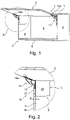
- Fig. 1
- eine perspektivische Ansicht auf ein Möbel mit einer Vorrichtung zur Bewegung eines geöffnet dargestellten Möbelteils,
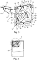
- Fig. 2
- den in
Fig. 1 umrandeten Bereich A in vergrößerter Darstellung, - Fig. 3
- die Bewegungsvorrichtung gemäß dem umrandeten Bereich A in
Fig. 1 in perspektivischer Ansicht ohne ein Abdeckelement der Vorrichtung, - Fig. 4
- einen teilweise geschnitten gezeigten Ausschnitt des Möbels mit der Vorrichtung gemäß
Fig. 1 ohne Abdeckelement jedoch bei geschlossen dargestelltem Möbelteil, - Fig. 5
- den in
Fig. 4 umrandeten Bereich B in vergrößerter Darstellung, - Fig. 6
- den in
Fig. 4 gezeigten Ausschnitt des Möbels mit der Vorrichtung teilweise geschnitten bei geöffnet dargestelltem Möbelteil, - Fig. 7
- den in
Fig. 6 umrandeten Bereich C in vergrößerter Darstellung, - Fig. 8
- das Möbel gemäß
Fig. 1 in der Teilansicht gemäßFig. 2 jedoch in einer aufgesetzten Montagestellung der Vorrichtung zur Bewegung des Möbelteils, - Fig. 9
- eine Seiten-Teilansicht auf das Möbel bei geöffnet dargestelltem Möbelteil, teilweise geschnitten,
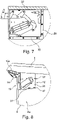
- Fig. 10
- den in
Figur 9 umrandeten Bereich D in vergrößerter Darstellung, - Fig. 11 und 12
- einen Ausschnitt im Bereich einer Verbindung zwischen einer teils geschnittenen Schwenkarm-Anordnung und einer Montageeinheit der Vorrichtung in zwei unterschiedlichen Montageschritten von der Seite und
- Fig. 13
- eine perspektivische Explosionsdarstellung der Vorrichtung gemäß den
Figuren 1 und 2 . - Für sich entsprechende Elemente unterschiedlicher Ausführungsbeispiele sind teils die gleichen Bezugszeichen verwendet.
-
Fig. 1 zeigt perspektivisch ein Möbel bzw. einen Oberschrank 1 mit einem kastenförmigen Möbelkorpus 2 und einem daran aufgenommenen Möbelteil, das als eine plattenartige Oberklappe 3 ausgebildet ist, welche in einer Offenstellung relativ zum Möbelkorpus 2 gezeigt ist. - Der Möbelkorpus 2 umfasst zwei gegenüberliegende, aufrechte Seitenwände 4 und 5, die unten mit einem Unterboden 6 und oben mit einem Oberboden 7 verbunden sind. Rückseitig ist der Möbelkorpus 2 von einer Rückwand 8 verschlossen.
- Zur Bewegung der Oberklappe 3 um eine horizontale Schwenkachse relativ zum Möbelkorpus 2 aus der in
Fig. 1 gezeigten Offenstellung in eine zum Möbelkorpus 2 frontseitig heranbewegte Schließstellung (s.Fig. 4 ,5 ) ist eine Bewegungsvorrichtung vorhanden, die als Oberklappenbeschlag 9 ausgestaltet ist. Der Oberklappenbeschlag 9 weist an der Seitenwand 4 eine erste Beschlageinheit 10 und an der Seitenwand 5 eine zweite Beschlageinheit 11 auf, die gleichartig aber zur funktionsrichtigen Anordnung an der jeweiligen Seitenwand 4 bzw. 5 seitenbezogen aufgebaut sind. - Jede Beschlageinheit 10 und 11 umfasst eine Basiseinheit 12, Führungsmittel 13 mit Gelenkhebeln und eine Montageeinheit in Form eine Montageplatte 15a, 15b. Über mehrere gelenkig gelagerte Gelenkhebel, welche als Schwenkarme 14.1 bis 14.7 einer Schwenkarm-Anordnung 14 vorhanden sind, ist die Basiseinheit 12 mit der Montageplatte 15a, 15b verbunden, welche fest an einer Innenseite der Oberklappe 3 z.B. versenkt in einer Materialausnehmung 36 befestigt ist.
- Außerdem weisen die Führungsmittel 13 einen mit einer Verstelleinheit 17 verstellbaren Kraftspeicher 16 zur Unterstützung der Öffnungsbewegung der Oberklappe 3 in die Offenposition bzw. Offenstellung und eine Dämpfervorrichtung 18 für eine gedämpfte Schließbewegung der Oberklappe 3 in die Schließposition bzw. Schließstellung auf.
- Die Basiseinheit 12 ist vorzugsweise aus einem Blechbauteil gebildet und umfasst eine ebene, flache bzw. dünne Grundplatte 19 und eine zur Grundplatte 19 gegenüberliegende flache dünne Abdeckplatte 20, welche lediglich in den
Fig. 1 und 2 dargestellt ist. - Außerdem ist stirnseitig an der Basiseinheit 12 ein Stirnabschnitt 21 vorhanden, dessen Außenseite quer zur Ebene der Grundplatte 19 ausgerichtet ist. Durch eine rechteckförmige Aussparung 22 im Stirnabschnitt 21 greifen die betreffenden Schwenkarme der Schwenkarm-Anordnung 14.
- Die in der Grundfläche z.B. viereckige bzw. z.B. rechteckige Grundplatte 12 weist demgemäß vier gerade verlaufende Grundplatten-Ränder 23 bis 26 auf, wobei im gezeigten Ausführungsbeispiel an den zwei benachbarten Grundplatten-Rändern 25 und 26 jeweils ein zur Ebene der Grundplatte 19 z.B. senkrecht hochstehender rechteck- bzw. streifenförmiger Wandabschnitt 27, 28 vorhanden ist. Die Wandabschnitte 27, 28 sind z.B. identisch in ihrer Höhe, welche vorzugsweise um ein vorgebbares Maß geringer ist als z.B. die Dicke des Wandelements des Möbels bzw. der Seitenwand 4 des Oberschranks 1, an welcher die Basiseinheit 12 der Beschlageinheit 10 angebracht wird. Wenn die Seitenwand 4 eine übliche Dicke a von 16 Millimeter aufweist (s.
Fig. 2 ), dann beträgt eine Höhe der Basiseinheit 12 zum Beispiel vorzugsweise 12 Millimeter oder weniger. Damit kann die Basiseinheit 12 in eine vorbereitet Materialausnehmung 31 versenkt bzw. bündig eingesetzt werden, wenn die Materialausnehmung 31 eine Tiefe von 12 Millimeter aufweist. Die Restbodendicke der Materialausnehmung 31 beträgt dann demgemäß 4 Millimeter. Die Höhe der Basiseinheit setzt sich neben der Höhe des Wandabschnitts 27, 28 z.B. zusätzlich aus der Dicke der Grundplatte 19 und der Dicke des Anlageflansches 29, 30 zusammen. Bei einer angenommenen Blechdicke von z.B. einem Millimeter und einer Höhe der Basiseinheit 12 von 12 Millimetern beträgt die Höhe des Wandabschnitts 27 bzw. 28 bspw. zehn Millimeter. - Damit die mechanische Schwächung der Seitenwand 4, 5 durch die Materialausnehmung 31 bzw. aufgrund des fehlenden Wandmaterials verglichen zur Seitenwand ohne Materialausnehmung 31 zu keinen unerwünschten Folgen führt, sind Anlageflansche 29, 30 vorhanden. Mit den Anlageflanschen 29, 30 und daran an- bzw. durchgreifenden Befestigungsmitteln wie zum Beispiel Schraubmittel 40 lässt sich die Beschlageinheit 10 bzw. die Basiseinheit 12 an der Seitenwand 4 fest anbringen, insbesondere positionsfest und spielfrei fixieren. Zur Stabilisierung der geschwächten Seitenwand 4, 5 im Bereich der Materialausnehmung 31, trägt außerdem die eingesetzte Basiseinheit 12 bei. Dabei wirkt vorteilhaft ein Flächenkontakt über die flächige Anlage der Außenseite der Basiseinheit 12 mit der Wandung der Materialausnehmung 31, was stabilisierend wirkt. Zusätzlich kann die Befestigung bzw. Haftwirkung durch Klebemittel, wie z.B. eine Klebschicht, zwischen der Basiseinheit 12 und der Materialaussparung 31 verbessert bzw. erhöht werden.
- An jeden Wandabschnitt 27 und 28 schließt ein rechtwinklig daran abgewinkelter Anlageflansch an, also am Wandabschnitt 27 der Anlageflansch 29 und am Wandabschnitt 28 der Anlageflansch 30. Die Anlageflansche 29, 30 sind ebenfalls rechteck- bzw. streifenförmig zum Beispiel zwischen 5 und 25 Millimeter breit, vorzugsweise circa 15 Millimeter breit.
- Die Befestigungsmittel, wie z.B. die Schraubmittel 40, greifen durch z.B. vorbereitete Durchgangslöcher in den Anlageflanschen 29, 30.
- Vorne im Bereich des Grundplatten-Randes 23 ist im montierten Zustand der Beschlageinheit 10 der rechteckförmige flache Stirnabschnitt 21 bündig versenkt zu einer vorderen, schmalen Stirnseite 4b der Seitenwand 4.
- Am oberseitigen Grundplatten-Rand 24 ist ein senkrecht zur Ebene der Grundplatte 19 z.B. rechtwinklig vorstehender Wandabschnitt 32 vorgesehen, jedoch ohne Anlageflansch, da der Grundplatten-Rand 24 unterseitig an den Oberboden 7 anschließt. Zur Befestigung der Basiseinheit 12 an dem Oberboden 7 greift eine Schraube 33 durch eine schräg ausgerichtete Durchlassöffnung in einem Winkelelement 34 und durch eine Öffnung 35 im Wandabschnitt 32, so dass die Schraube 33 schräg in den Oberboden 7 einschraubbar ist, womit die Basiseinheit 12 nach oben und zur Seitenwand 4 hingezogen wird.
- Auch die Montageplatte 15a, 15b ist vorteilhaft in einer entsprechenden Materialausnehmung 36 in der Oberklappe 3 versenkt, vorzugsweise bündig zur Innenseite der Oberklappe 3 untergebracht.
- Die Beschlageinheit 10 bzw. die Basiseinheit 12 kann an dem Möbelkorpus 2 auch ohne eine Materialausnehmung angebracht werden (s.
Fig. 8 ). Dazu greifen Schraubmittel 37 durch die Abdeckplatte 20 und die Löcher in den Anlageflansche 29 und 30 und durch nicht dargestellte Adaptermittel, die zwischen der Unterseite der Anlageflansche 29, 30 und der Innenseite 4a der Seitenwand 4 passend einsetzbar sind, mit entsprechenden Öffnungen darin zum Durchgreifen der Schraubmittel 37, die über die Adaptermittel hindurchreichend in die Seitenwand 4 einschraubbar sind. Entsprechend ist inFig. 8 auch eine weitere Variante einer Montageeinheit 15a bzw. 15b vorhanden, welche z.B. auf die spezielle Anbringposition der Beschlageinheit 10 am Möbelkorpus 2 angepasst ist. -
Figur 10 zeigt den oberen Abschnitt des Oberschranks 1 bei geöffneter Oberklappe 3, wobei die Oberklappe 3 teilweise und die Montageplatte 15a komplett geschnitten dargestellt ist. Demgemäß ist die Montageplatte 15a in der passenden Materialausnehmung 36 nahezu vollständig versenkt aufgenommen. Die Montageplatte 15a ist in der Grundform z.B. mit der Grundform der Basiseinheit 12 vergleichbar und weist eine ebene Grundplatte 42, einen daran hochstehenden Wandabschnitt 43 und einen winklig nach außen am Wandabschnitt 43 abstehenden Anlageflansch 44 auf. Eine Oberseite 44a der Montageplatte 15a bzw. der Anlageflansch 44 und eine daran lösbar aufgesteckte, deckelartige, flache bzw. dünne Abdeckung 41 stehen z.B. geringfügig über die Innenseite 3a der Oberklappe 3 über. Die Materialausnehmung 36 umfasst eine tiefere Haupttasche 36a und eine flachere Nebentasche 36b, in welcher der Anlageflansch 44 der Montageplatte 15a aufgenommen ist. Im vertieften Bereich der Montageplatte 15a oberhalb der Grundplatte 42 und innerhalb der Höhe des Wandabschnitts 43 sind Verstellmittel 45 zur Verstellung der Relativposition zwischen der Schwenkarm-Anordnung 14 und der Montageplatte 15a untergebracht. Von der Schwenkarm-Anordnung 14 reicht der Schwenkarm 14.1 bis in den Bereich der Montageplatte 15a. - Die Verstellmittel 45 der Montageplatte 15a umfassen beispielsweise Tiefenverstellmittel 46 mit z.B. einer Stellschraube 47, Seitenverstellmittel 48 mit z.B. einem Exzenter 49 und/oder Höhenverstellmittel 50 mit z.B. einer Verstellschnecke.
- Mit den Tiefenverstellmitteln 46 erfolgt eine Verstellung der Relativposition zwischen der Schwenkarm-Anordnung 14 und der Montageplatte 15a in die Richtungen gemäß des Doppelpfeils P1.
- Mit den Seitenverstellmitteln 48, welche als Festlager vorhanden sind, erfolgt eine Verstellung der Relativposition zwischen der Schwenkarm-Anordnung 14 und der Montageplatte 15a in die Richtungen gemäß des Doppelpfeils P2.
- Mit den Höhenverstellmitteln 50 erfolgt eine Verstellung der Relativposition zwischen der Schwenkarm-Anordnung 14 und der Montageplatte 15a in die Richtungen gemäß des Doppelpfeils P3.
- Die Montage zur lösbaren Anbringung der Oberklappe 3 mit der Montageplatte 15a bzw. 15b am vorderen Ende der Schwenkarmanordnung 14 ist in den
Figuren 11 und 12 verdeutlicht. Hierfür sind Schnell-Verbindungsmittel 52 vorgesehen, die an der Schwenkarm-Anordnung 14 einen schwenkbaren Rasthebel 53 und einen Stift 54 nahe am Rasthebel 53 und einen weiteren zum Rasthebel 53 beabstandeten Stift 55 umfasst, wobei die Längsachsen der Stifte 54, 55 parallel zur Schwenkachse des Rasthebels 53 verlaufen. - An der Montageplatte 15a, 15b umfassen die Schnell-Verbindungsmittel 52 eine Rastnase 56 und einen Rasthaken 57, die auf den Rasthebel 53, den Stift 54 und den Stift 55 passend abgestimmt ausgebildet sind.
- Nach dem positionsrichtigen Heranführen der Oberklappe 3 mit den Montageplatten 15a, 15b an die Schwenkarmanordnungen 14 kommt bei gegen den Uhrzeigersinn verschwenktem Rasthebel 53 der Stift 54 in einer Kerbe des Rasthaken 57 in eine Anschlagstellung und gleichzeitig der Stift 55 in einer Einkerbung des Rasthakens 57. Dann wird der Rasthebel 53 manuell im Uhrzeigersinn gemäß P4 verschwenkt, so dass eine Nase des Rasthebels 53 in eine Vertiefung der Rastnase 56 eingreift und die feste Verankerung eingerichtet ist.
- Die Demontage erfolgt durch die umgekehrte Reihenfolge der Schritte, die zur Montage nötig sind.
-
Figur 13 zeigt eine perspektivische Explosionsdarstellung des Oberklappenbeschlags 9. InFigur 13 zu erkennen ist die sandwichartige Ausgestaltung des ersten Schwenkarms 14.1, des dritten Schwenkarms 14.3, des fünften Schwenkarms 14.5 und des siebten Schwenkarms 14.7. Der erste Schwenkarm 14.1 umfasst zwei Schwenkhebel 38a, 38b in welchen bzw. zwischen welchen ein Schwenkhebel 39 des zweiten Schwenkarms 14.2 im angeordneten Zustand schwenkbeweglich gelagert ist. Analog sind weiteren Schwenkhebel 14.3 - 14.7 angeordnet. Vorteilhafterweise ist ein Schwenkhebel 58 des vierten Schwenkarms 14.4 sowohl am ersten, am dritten und am fünften Schwenkarm 14.1, 14.2, 14.3 schwenkbeweglich gelagert. Beispielsweise umfassen der zweite, der vierte und der sechste Schwenkarm 14.2, 14.4, 14.6 jeweils einen einzigen Schwenkhebel 39, 58, 59. Die Schwenkhebel 39, 58, 59 sind vorteilhafterweise im angeordneten Zustand derart schwenkbeweglich gelagert, dass sie sich bei einer Öffnungsoder Schließbewegung der Oberklappe 3 in einer gemeinsamen Bewegungsebene bewegen. Jeweils die linken Schwenkhebel 38b oder die rechten Schwenkhebel 38a des ersten, des dritten, des fünften und des siebten Schwenkarms 14.1, 14.3, 14.5, 14.7 bewegen sich im angeordneten Zustand vorteilhafterweise ebenfalls entlang einer gemeinsamen Bewegungsebene. Vorteilhafterweise sind die Bewegungsebenen parallel zueinander ausgerichtet. Der dritte, der fünfte und der siebte Schwenkarm 14.3, 14.5, 14.7 ist vorteilhafterweise an einem Lager 60 - 62 (Figur 3 ) beidseitig an der Basiseinheit 12 beweglich gelagert, insbesondere an der Grundplatte 19 und an der Abdeckplatte 20.Bezugszeichenliste 1 Oberschrank 34 Winkelelement 2 Möbelkorpus 35 Öffnung 3 Oberklappe 36 Materialausnehmung 3a Innenseite 36a Haupttasche 4 Seitenwand 36b Nebentasche 4a Innenseite 37 Schraubmittel 4b Stirnseite 38a, 38b Schwenkhebel 5 Seitenwand 39 Schwenkhebel 6 Unterboden 40 Schraubmittel 7 Oberboden 41 Abdeckung 8 Rückwand 42 Grundplatte 9 Oberklappenbeschlag 43 Wandabschnitt 10 Beschlageinheit 44 Anlageflansch 11 Beschlageinheit 44a Oberseite 12 Basiseinheit 45 Verstellmittel 13 Führungsmittel 46 Tiefen-verstellmittel Stellschraube 14 SchwenkarmAnordnung 47 14.1-14.7 Schwenkarm 48 Seiten-verstellmittel 15a, 15b Montageplatte 16 Kraftspeicher 49 Exzenter 17 Verstelleinheit 50 Höhenverstellmittel 18 Dämpfervorrichtung 52 Schnellverbindungs-mittel 19 Grundplatte 20 Abdeckplatte 53 Rasthebel 21 Stirnabschnitt 54 Stift 22 Aussparung 55 Stift 23 - 26 Grundplatten-Rand 56 Rastnase 27, 28 Wandabschnitt 57 Rasthaken 29, 30 Anlageflansch 58 Schwenkhebel 31 Materialausnehmung 59 Schwenkhebel 32 Wandabschnitt 60 - 62 Lager 33 Schraube
Claims (9)
- Vorrichtung (9) zur Bewegung eines an einem Möbelkorpus (2) eines Möbels (1) aufgenommenen Möbelteils (3), wobei die Vorrichtung (9) Führungsmittel aufweist, mit welchen bei montierter Vorrichtung (9) am Möbel (1) das Möbelteil (3) aus einer Schließposition in eine Offenposition relativ zum Möbelkorpus (2) und zurück bewegbar ist, wobei das Möbelteil (3) in der Schließposition eine maximal an eine Frontseite (4b) des Möbelkorpus (2) heranbewegte Position einnimmt,wobei die Vorrichtung (9) ein Gehäuse aufweist, an welchem die Führungsmittel beweglich gelagert sind, wobei Führungsmittel als Gelenkhebel (14) ausgebildet sind, wobei ein erster und ein zweiter Gelenkhebel (14.1, 14.2) vorhanden ist, wobei der erste und der zweite Gelenkhebel (14.1, 14.2) gelenkig miteinander verbunden sind, wobei der erste Gelenkhebel (14.1) sandwichartig mit wenigstens zwei Hebelarmen (38a, 38b) ausgebildet ist, sodass der zweite Gelenkhebel (14.2) zwischen den zwei Hebelarmen (38a, 38b) des ersten Gelenkhebels (14.1) beweglich aufgenommen ist, wobei der erste Gelenkhebel (14.1) an Montagemittel (15a, 15b) der Vorrichtung (9) lösbar anordenbar ausgebildet ist, wobei die Montagemittel (15a, 15b) an das Möbelteil (3) montierbar sind, wobei die Führungsmittel einen dritten Gelenkhebel (14.3) umfassen, wobei der dritte Gelenkhebel (14.3) sandwichartig mit wenigstens zwei Hebelarmen ausgebildet ist, sodass der zweite Gelenkhebel (14.2) zwischen den zwei Hebelarmen des dritten Gelenkhebels (14.3) beweglich aufgenommen ist, dadurch gekennzeichnet, dassdie Führungsmittel einen vierten Gelenkhebel (14.4) umfassen, wobei der vierte Gelenkhebel zwischen den zwei Hebelarmen des dritten Gelenkhebels (14.3) beweglich aufgenommen ist, wobei der vierte Gelenkhebel (14.4) zwischen den zwei Hebelarmen des ersten Gelenkhebels (14.1) beweglich aufgenommen ist.
- Vorrichtung (9) zur Bewegung eines an einem Möbelkorpus (2) eines Möbels (1) aufgenommenen Möbelteils (3) nach einem der vorangegangenen Ansprüche, dadurch gekennzeichnet, dass die Führungsmittel einen fünften Gelenkhebel (14.5) umfassen, wobei der fünfte Gelenkhebel (14.5) sandwichartig mit wenigstens zwei Hebelarmen ausgebildet ist, sodass der vierte Gelenkhebel (14.4) zwischen den zwei Hebelarmen des fünften Gelenkhebels (14.5) beweglich aufgenommen ist.
- Vorrichtung (9) zur Bewegung eines an einem Möbelkorpus (2) eines Möbels (1) aufgenommenen Möbelteils (3) nach einem der vorangegangenen Ansprüche, dadurch gekennzeichnet, dass die Führungsmittel einen sechsten Gelenkhebel (14.6) umfassen, wobei der sechste Gelenkhebel (14.6) zwischen den zwei Hebelarmen des fünften Gelenkhebels (14.5) beweglich aufgenommen ist.
- Vorrichtung (9) zur Bewegung eines an einem Möbelkorpus (2) eines Möbels (1) aufgenommenen Möbelteils (3) nach einem der vorangegangenen Ansprüche, dadurch gekennzeichnet, dass die Führungsmittel einen siebten Gelenkhebel (14.7) umfassen, wobei der siebte Gelenkhebel (14.7) sandwichartig mit wenigstens zwei Hebelarmen ausgebildet ist, sodass der sechste Gelenkhebel (14.6) zwischen den zwei Hebelarmen des siebten Gelenkhebels (14.7) beweglich aufgenommen ist.
- Vorrichtung (9) zur Bewegung eines an einem Möbelkorpus (2) eines Möbels (1) aufgenommenen Möbelteils (3) nach einem der vorangegangenen Ansprüche, dadurch gekennzeichnet, dass eine Dicke eines Gelenkhebels (14.1 - 14.7) kleiner oder gleich 6mm ist.
- Vorrichtung (9) zur Bewegung eines an einem Möbelkorpus (2) eines Möbels (1) aufgenommenen Möbelteils (3) nach einem der vorangegangenen Ansprüche, dadurch gekennzeichnet, dass die Vorrichtung (9) ein Kraftspeicher (16) aufweist, welcher auf die Führungsmittel wirkt, wobei der Kraftspeicher (16) ein Federpaket bestehend aus mehreren, insbesondere aus drei oder mehr nebeneinander vorhandenen Federelementen umfasst.
- Vorrichtung (9) zur Bewegung eines an einem Möbelkorpus (2) eines Möbels (1) aufgenommenen Möbelteils (3) nach einem der vorangegangenen Ansprüche, dadurch gekennzeichnet, dass der Kraftspeicher (16) mit dem sechsten und/oder dem siebten Gelenkhebel (14.6, 14.7) verbunden ist.
- Vorrichtung (9) zur Bewegung eines an einem Möbelkorpus (2) eines Möbels (1) aufgenommenen Möbelteils (3) nach einem der vorangegangenen Ansprüche, dadurch gekennzeichnet, dass das Gehäuse einen Grundkörper (19) und einen Deckel (20) aufweist, wobei zumindest ein Gelenkhebel (14.3, 14.5, 14.7) der Führungsmittel an einem Lager (60 - 62) am Gehäuse schwenkbeweglich gelagert ist, wobei das Lager (60 - 62) zweiseitig am Gehäuse gehalten ist.
- Möbel (1) mit einer Vorrichtung (9) zur Bewegung eines an einem Möbelkorpus (2) eines Möbels (1) aufgenommenen Möbelteils (3) nach einem der vorangegangenen Ansprüche.
Applications Claiming Priority (1)
| Application Number | Priority Date | Filing Date | Title |
|---|---|---|---|
| DE202017102809.7U DE202017102809U1 (de) | 2017-05-10 | 2017-05-10 | Vorrichtung zur Bewegung eines an einem Möbelkorpus eines Möbels aufgenommenen Möbelteils |
Publications (2)
| Publication Number | Publication Date |
|---|---|
| EP3401476A1 EP3401476A1 (de) | 2018-11-14 |
| EP3401476B1 true EP3401476B1 (de) | 2022-12-14 |
Family
ID=62116793
Family Applications (1)
| Application Number | Title | Priority Date | Filing Date |
|---|---|---|---|
| EP18171001.3A Active EP3401476B1 (de) | 2017-05-10 | 2018-05-07 | Vorrichtung zur bewegung eines an einem möbelkorpus eines möbels aufgenommenen möbelteils |
Country Status (4)
| Country | Link |
|---|---|
| EP (1) | EP3401476B1 (de) |
| DE (1) | DE202017102809U1 (de) |
| ES (1) | ES2940353T3 (de) |
| HU (1) | HUE061558T2 (de) |
Families Citing this family (10)
| Publication number | Priority date | Publication date | Assignee | Title |
|---|---|---|---|---|
| DE202018102088U1 (de) | 2018-04-17 | 2019-07-18 | Grass Gmbh | Vorrichtung zur Bewegung eines Möbelteils und Möbel |
| DE202018102087U1 (de) * | 2018-04-17 | 2019-07-18 | Grass Gmbh | Rahmenelement eines Möbelteil-Rahmens und Möbelteil |
| AT522092B1 (de) | 2018-12-20 | 2020-08-15 | Blum Gmbh Julius | Möbelantrieb |
| AT521965B1 (de) | 2019-02-15 | 2020-07-15 | Blum Gmbh Julius | Möbelscharnier |
| ES2882801T3 (es) * | 2019-04-02 | 2021-12-02 | Flap Competence Center Kft | Herraje de solapa |
| AT522457B1 (de) * | 2019-05-17 | 2020-11-15 | Blum Gmbh Julius | Möbelbeschlag |
| AT522656B1 (de) * | 2019-05-17 | 2025-04-15 | Blum Gmbh Julius | Möbelantrieb |
| CN110778234B (zh) * | 2019-10-21 | 2024-10-01 | 宁波市维特建筑五金有限公司 | 一种多功能隐藏式分体铰链 |
| DE202023100322U1 (de) * | 2023-01-24 | 2023-02-17 | Flap Competence Center Kft | Möbel |
| DE102024117710A1 (de) * | 2024-06-24 | 2025-12-24 | Hettich-Oni Gmbh & Co. Kg | Scharnier |
Citations (3)
| Publication number | Priority date | Publication date | Assignee | Title |
|---|---|---|---|---|
| DE202013008777U1 (de) * | 2013-10-07 | 2015-01-08 | Grass Gmbh & Co. Kg | Scharnier für ein Möbelteil und Möbel |
| WO2016174061A1 (en) * | 2015-04-30 | 2016-11-03 | Arturo Salice S.P.A. | Hinge for furniture leaves that open downwardly |
| WO2018192819A1 (de) * | 2017-04-18 | 2018-10-25 | Hettich-Oni Gmbh & Co. Kg | Möbelplatte mit einem klappenbeschlag und möbelkorpus sowie möbel mit einer derartigen möbelplatte |
Family Cites Families (3)
| Publication number | Priority date | Publication date | Assignee | Title |
|---|---|---|---|---|
| US2120685A (en) * | 1936-07-18 | 1938-06-14 | Soss | Automatic latch concealed hinge |
| ITMO20050171A1 (it) * | 2005-07-07 | 2007-01-08 | Tgn Spa | ''cerniera a scatto perfezionata per il sostegno di un elemento di chiusura''. |
| CN104775701B (zh) * | 2015-04-02 | 2017-03-01 | 伍志勇 | 用于家具上翻门的锁离调节机构 |
-
2017
- 2017-05-10 DE DE202017102809.7U patent/DE202017102809U1/de active Active
-
2018
- 2018-05-07 EP EP18171001.3A patent/EP3401476B1/de active Active
- 2018-05-07 HU HUE18171001A patent/HUE061558T2/hu unknown
- 2018-05-07 ES ES18171001T patent/ES2940353T3/es active Active
Patent Citations (3)
| Publication number | Priority date | Publication date | Assignee | Title |
|---|---|---|---|---|
| DE202013008777U1 (de) * | 2013-10-07 | 2015-01-08 | Grass Gmbh & Co. Kg | Scharnier für ein Möbelteil und Möbel |
| WO2016174061A1 (en) * | 2015-04-30 | 2016-11-03 | Arturo Salice S.P.A. | Hinge for furniture leaves that open downwardly |
| WO2018192819A1 (de) * | 2017-04-18 | 2018-10-25 | Hettich-Oni Gmbh & Co. Kg | Möbelplatte mit einem klappenbeschlag und möbelkorpus sowie möbel mit einer derartigen möbelplatte |
Also Published As
| Publication number | Publication date |
|---|---|
| ES2940353T3 (es) | 2023-05-05 |
| HUE061558T2 (hu) | 2023-07-28 |
| EP3401476A1 (de) | 2018-11-14 |
| DE202017102809U1 (de) | 2018-08-13 |
Similar Documents
| Publication | Publication Date | Title |
|---|---|---|
| EP3401476B1 (de) | Vorrichtung zur bewegung eines an einem möbelkorpus eines möbels aufgenommenen möbelteils | |
| EP3561209B1 (de) | Vorrichtung zur bewegung eines möbelteils und möbel | |
| EP3401477B1 (de) | Möbel | |
| EP3556978B1 (de) | Vorrichtung zur bewegung eines an einem möbelkorpus eines möbels aufgenommenen möbelteils | |
| EP3561207B1 (de) | Verbindungsmittel und möbelteil | |
| EP3401481B1 (de) | Vorrichtung zur bewegung eines an einem möbelkorpus aufgenommenen möbelteils und möbel | |
| EP3735152B1 (de) | Anordnung einer möbelplatte und eines bewegungsbeschlages mit integriertem montageelement für den bewegungsbeschlag, möbelkörper und möbel, die eine solche möbelplatte enthalten | |
| EP3401479B1 (de) | Oberklappenbeschlag | |
| EP3652400B1 (de) | Vorrichtung zur bewegung eines möbelteils und möbel | |
| DE3610102C2 (de) | ||
| EP3401478A1 (de) | Vorrichtung zur bewegung eines an einem möbelkorpus eines möbels aufgenommenen möbelteils | |
| EP3401482B1 (de) | Möbel mit einer vorrichtung zur bewegung eines möbelteils | |
| DE3405343C2 (de) | ||
| DE3026728C2 (de) | Scharnierkonstruktion für Stahlzargen | |
| DE2524419C2 (de) | Scharnier zum Anlenken einer Glastür an einem Möbelkörper | |
| AT520767B1 (de) | Anordnung aus einem Auflagesteg für einen Schubladenboden und einer Haltevorrichtung | |
| EP3623554B1 (de) | Vorrichtung zur bewegung eines an einem möbelkorpus eines möbels aufgenommenen möbelteils | |
| DE102018130012A1 (de) | Schubkasten und Möbel | |
| WO2024016032A1 (de) | Schubladenseitenwand für eine schublade | |
| DE112021003269T5 (de) | Gestänge- und Scharnieranordnung mit mehreren hochbelastbaren Verstrebungen für schwenkbar gelagerte Ausstellfenster | |
| DE20120238U1 (de) | Montageplatte zur verstellbaren Halterung von Möbelscharnieren am Korpus von Möbelstücken | |
| EP3556977B1 (de) | Rahmenelement für einen möbelteil-rahmen und möbelteil | |
| DE8906122U1 (de) | Möbel, insbesondere Eckmöbel mit einer Rückwand, aus zwei im Winkel zueinander liegenden Korpuswänden | |
| DE202008002544U1 (de) | Halter für Frontblenden |
Legal Events
| Date | Code | Title | Description |
|---|---|---|---|
| PUAI | Public reference made under article 153(3) epc to a published international application that has entered the european phase |
Free format text: ORIGINAL CODE: 0009012 |
|
| STAA | Information on the status of an ep patent application or granted ep patent |
Free format text: STATUS: THE APPLICATION HAS BEEN PUBLISHED |
|
| AK | Designated contracting states |
Kind code of ref document: A1 Designated state(s): AL AT BE BG CH CY CZ DE DK EE ES FI FR GB GR HR HU IE IS IT LI LT LU LV MC MK MT NL NO PL PT RO RS SE SI SK SM TR |
|
| AX | Request for extension of the european patent |
Extension state: BA ME |
|
| RAP1 | Party data changed (applicant data changed or rights of an application transferred) |
Owner name: GRASS GMBH |
|
| STAA | Information on the status of an ep patent application or granted ep patent |
Free format text: STATUS: REQUEST FOR EXAMINATION WAS MADE |
|
| 17P | Request for examination filed |
Effective date: 20190430 |
|
| RBV | Designated contracting states (corrected) |
Designated state(s): AL AT BE BG CH CY CZ DE DK EE ES FI FR GB GR HR HU IE IS IT LI LT LU LV MC MK MT NL NO PL PT RO RS SE SI SK SM TR |
|
| STAA | Information on the status of an ep patent application or granted ep patent |
Free format text: STATUS: EXAMINATION IS IN PROGRESS |
|
| 17Q | First examination report despatched |
Effective date: 20200616 |
|
| GRAP | Despatch of communication of intention to grant a patent |
Free format text: ORIGINAL CODE: EPIDOSNIGR1 |
|
| STAA | Information on the status of an ep patent application or granted ep patent |
Free format text: STATUS: GRANT OF PATENT IS INTENDED |
|
| GRAJ | Information related to disapproval of communication of intention to grant by the applicant or resumption of examination proceedings by the epo deleted |
Free format text: ORIGINAL CODE: EPIDOSDIGR1 |
|
| STAA | Information on the status of an ep patent application or granted ep patent |
Free format text: STATUS: EXAMINATION IS IN PROGRESS |
|
| INTG | Intention to grant announced |
Effective date: 20220511 |
|
| INTC | Intention to grant announced (deleted) | ||
| GRAP | Despatch of communication of intention to grant a patent |
Free format text: ORIGINAL CODE: EPIDOSNIGR1 |
|
| STAA | Information on the status of an ep patent application or granted ep patent |
Free format text: STATUS: GRANT OF PATENT IS INTENDED |
|
| INTG | Intention to grant announced |
Effective date: 20220706 |
|
| GRAS | Grant fee paid |
Free format text: ORIGINAL CODE: EPIDOSNIGR3 |
|
| GRAA | (expected) grant |
Free format text: ORIGINAL CODE: 0009210 |
|
| STAA | Information on the status of an ep patent application or granted ep patent |
Free format text: STATUS: THE PATENT HAS BEEN GRANTED |
|
| AK | Designated contracting states |
Kind code of ref document: B1 Designated state(s): AL AT BE BG CH CY CZ DE DK EE ES FI FR GB GR HR HU IE IS IT LI LT LU LV MC MK MT NL NO PL PT RO RS SE SI SK SM TR |
|
| REG | Reference to a national code |
Ref country code: GB Ref legal event code: FG4D Free format text: NOT ENGLISH |
|
| REG | Reference to a national code |
Ref country code: CH Ref legal event code: EP |
|
| REG | Reference to a national code |
Ref country code: DE Ref legal event code: R096 Ref document number: 502018011209 Country of ref document: DE |
|
| REG | Reference to a national code |
Ref country code: IE Ref legal event code: FG4D Free format text: LANGUAGE OF EP DOCUMENT: GERMAN |
|
| REG | Reference to a national code |
Ref country code: AT Ref legal event code: REF Ref document number: 1537745 Country of ref document: AT Kind code of ref document: T Effective date: 20230115 |
|
| REG | Reference to a national code |
Ref country code: LT Ref legal event code: MG9D |
|
| REG | Reference to a national code |
Ref country code: NL Ref legal event code: MP Effective date: 20221214 |
|
| PG25 | Lapsed in a contracting state [announced via postgrant information from national office to epo] |
Ref country code: SE Free format text: LAPSE BECAUSE OF FAILURE TO SUBMIT A TRANSLATION OF THE DESCRIPTION OR TO PAY THE FEE WITHIN THE PRESCRIBED TIME-LIMIT Effective date: 20221214 Ref country code: NO Free format text: LAPSE BECAUSE OF FAILURE TO SUBMIT A TRANSLATION OF THE DESCRIPTION OR TO PAY THE FEE WITHIN THE PRESCRIBED TIME-LIMIT Effective date: 20230314 Ref country code: LT Free format text: LAPSE BECAUSE OF FAILURE TO SUBMIT A TRANSLATION OF THE DESCRIPTION OR TO PAY THE FEE WITHIN THE PRESCRIBED TIME-LIMIT Effective date: 20221214 Ref country code: FI Free format text: LAPSE BECAUSE OF FAILURE TO SUBMIT A TRANSLATION OF THE DESCRIPTION OR TO PAY THE FEE WITHIN THE PRESCRIBED TIME-LIMIT Effective date: 20221214 |
|
| REG | Reference to a national code |
Ref country code: ES Ref legal event code: FG2A Ref document number: 2940353 Country of ref document: ES Kind code of ref document: T3 Effective date: 20230505 |
|
| PG25 | Lapsed in a contracting state [announced via postgrant information from national office to epo] |
Ref country code: RS Free format text: LAPSE BECAUSE OF FAILURE TO SUBMIT A TRANSLATION OF THE DESCRIPTION OR TO PAY THE FEE WITHIN THE PRESCRIBED TIME-LIMIT Effective date: 20221214 Ref country code: LV Free format text: LAPSE BECAUSE OF FAILURE TO SUBMIT A TRANSLATION OF THE DESCRIPTION OR TO PAY THE FEE WITHIN THE PRESCRIBED TIME-LIMIT Effective date: 20221214 Ref country code: HR Free format text: LAPSE BECAUSE OF FAILURE TO SUBMIT A TRANSLATION OF THE DESCRIPTION OR TO PAY THE FEE WITHIN THE PRESCRIBED TIME-LIMIT Effective date: 20221214 Ref country code: GR Free format text: LAPSE BECAUSE OF FAILURE TO SUBMIT A TRANSLATION OF THE DESCRIPTION OR TO PAY THE FEE WITHIN THE PRESCRIBED TIME-LIMIT Effective date: 20230315 |
|
| PG25 | Lapsed in a contracting state [announced via postgrant information from national office to epo] |
Ref country code: NL Free format text: LAPSE BECAUSE OF FAILURE TO SUBMIT A TRANSLATION OF THE DESCRIPTION OR TO PAY THE FEE WITHIN THE PRESCRIBED TIME-LIMIT Effective date: 20221214 |
|
| REG | Reference to a national code |
Ref country code: HU Ref legal event code: AG4A Ref document number: E061558 Country of ref document: HU |
|
| PG25 | Lapsed in a contracting state [announced via postgrant information from national office to epo] |
Ref country code: SM Free format text: LAPSE BECAUSE OF FAILURE TO SUBMIT A TRANSLATION OF THE DESCRIPTION OR TO PAY THE FEE WITHIN THE PRESCRIBED TIME-LIMIT Effective date: 20221214 Ref country code: RO Free format text: LAPSE BECAUSE OF FAILURE TO SUBMIT A TRANSLATION OF THE DESCRIPTION OR TO PAY THE FEE WITHIN THE PRESCRIBED TIME-LIMIT Effective date: 20221214 Ref country code: PT Free format text: LAPSE BECAUSE OF FAILURE TO SUBMIT A TRANSLATION OF THE DESCRIPTION OR TO PAY THE FEE WITHIN THE PRESCRIBED TIME-LIMIT Effective date: 20230414 Ref country code: EE Free format text: LAPSE BECAUSE OF FAILURE TO SUBMIT A TRANSLATION OF THE DESCRIPTION OR TO PAY THE FEE WITHIN THE PRESCRIBED TIME-LIMIT Effective date: 20221214 Ref country code: CZ Free format text: LAPSE BECAUSE OF FAILURE TO SUBMIT A TRANSLATION OF THE DESCRIPTION OR TO PAY THE FEE WITHIN THE PRESCRIBED TIME-LIMIT Effective date: 20221214 |
|
| PG25 | Lapsed in a contracting state [announced via postgrant information from national office to epo] |
Ref country code: SK Free format text: LAPSE BECAUSE OF FAILURE TO SUBMIT A TRANSLATION OF THE DESCRIPTION OR TO PAY THE FEE WITHIN THE PRESCRIBED TIME-LIMIT Effective date: 20221214 Ref country code: PL Free format text: LAPSE BECAUSE OF FAILURE TO SUBMIT A TRANSLATION OF THE DESCRIPTION OR TO PAY THE FEE WITHIN THE PRESCRIBED TIME-LIMIT Effective date: 20221214 Ref country code: IS Free format text: LAPSE BECAUSE OF FAILURE TO SUBMIT A TRANSLATION OF THE DESCRIPTION OR TO PAY THE FEE WITHIN THE PRESCRIBED TIME-LIMIT Effective date: 20230414 Ref country code: AL Free format text: LAPSE BECAUSE OF FAILURE TO SUBMIT A TRANSLATION OF THE DESCRIPTION OR TO PAY THE FEE WITHIN THE PRESCRIBED TIME-LIMIT Effective date: 20221214 |
|
| REG | Reference to a national code |
Ref country code: DE Ref legal event code: R097 Ref document number: 502018011209 Country of ref document: DE |
|
| PLBE | No opposition filed within time limit |
Free format text: ORIGINAL CODE: 0009261 |
|
| STAA | Information on the status of an ep patent application or granted ep patent |
Free format text: STATUS: NO OPPOSITION FILED WITHIN TIME LIMIT |
|
| PG25 | Lapsed in a contracting state [announced via postgrant information from national office to epo] |
Ref country code: DK Free format text: LAPSE BECAUSE OF FAILURE TO SUBMIT A TRANSLATION OF THE DESCRIPTION OR TO PAY THE FEE WITHIN THE PRESCRIBED TIME-LIMIT Effective date: 20221214 |
|
| 26N | No opposition filed |
Effective date: 20230915 |
|
| PG25 | Lapsed in a contracting state [announced via postgrant information from national office to epo] |
Ref country code: SI Free format text: LAPSE BECAUSE OF FAILURE TO SUBMIT A TRANSLATION OF THE DESCRIPTION OR TO PAY THE FEE WITHIN THE PRESCRIBED TIME-LIMIT Effective date: 20221214 |
|
| REG | Reference to a national code |
Ref country code: CH Ref legal event code: PL |
|
| PG25 | Lapsed in a contracting state [announced via postgrant information from national office to epo] |
Ref country code: MC Free format text: LAPSE BECAUSE OF FAILURE TO SUBMIT A TRANSLATION OF THE DESCRIPTION OR TO PAY THE FEE WITHIN THE PRESCRIBED TIME-LIMIT Effective date: 20221214 |
|
| GBPC | Gb: european patent ceased through non-payment of renewal fee |
Effective date: 20230507 |
|
| REG | Reference to a national code |
Ref country code: BE Ref legal event code: MM Effective date: 20230531 |
|
| PG25 | Lapsed in a contracting state [announced via postgrant information from national office to epo] |
Ref country code: MC Free format text: LAPSE BECAUSE OF FAILURE TO SUBMIT A TRANSLATION OF THE DESCRIPTION OR TO PAY THE FEE WITHIN THE PRESCRIBED TIME-LIMIT Effective date: 20221214 Ref country code: LU Free format text: LAPSE BECAUSE OF NON-PAYMENT OF DUE FEES Effective date: 20230507 Ref country code: LI Free format text: LAPSE BECAUSE OF NON-PAYMENT OF DUE FEES Effective date: 20230531 Ref country code: CH Free format text: LAPSE BECAUSE OF NON-PAYMENT OF DUE FEES Effective date: 20230531 |
|
| REG | Reference to a national code |
Ref country code: IE Ref legal event code: MM4A |
|
| PG25 | Lapsed in a contracting state [announced via postgrant information from national office to epo] |
Ref country code: IE Free format text: LAPSE BECAUSE OF NON-PAYMENT OF DUE FEES Effective date: 20230507 |
|
| PG25 | Lapsed in a contracting state [announced via postgrant information from national office to epo] |
Ref country code: IE Free format text: LAPSE BECAUSE OF NON-PAYMENT OF DUE FEES Effective date: 20230507 Ref country code: GB Free format text: LAPSE BECAUSE OF NON-PAYMENT OF DUE FEES Effective date: 20230507 |
|
| PG25 | Lapsed in a contracting state [announced via postgrant information from national office to epo] |
Ref country code: IT Free format text: LAPSE BECAUSE OF FAILURE TO SUBMIT A TRANSLATION OF THE DESCRIPTION OR TO PAY THE FEE WITHIN THE PRESCRIBED TIME-LIMIT Effective date: 20221214 Ref country code: BE Free format text: LAPSE BECAUSE OF NON-PAYMENT OF DUE FEES Effective date: 20230531 |
|
| PG25 | Lapsed in a contracting state [announced via postgrant information from national office to epo] |
Ref country code: BG Free format text: LAPSE BECAUSE OF FAILURE TO SUBMIT A TRANSLATION OF THE DESCRIPTION OR TO PAY THE FEE WITHIN THE PRESCRIBED TIME-LIMIT Effective date: 20221214 |
|
| PG25 | Lapsed in a contracting state [announced via postgrant information from national office to epo] |
Ref country code: BG Free format text: LAPSE BECAUSE OF FAILURE TO SUBMIT A TRANSLATION OF THE DESCRIPTION OR TO PAY THE FEE WITHIN THE PRESCRIBED TIME-LIMIT Effective date: 20221214 |
|
| REG | Reference to a national code |
Ref country code: DE Ref legal event code: R082 Ref document number: 502018011209 Country of ref document: DE Representative=s name: RAVENSPAT PATENTANWAELTE PARTNERSCHAFT MBB, DE |
|
| PGFP | Annual fee paid to national office [announced via postgrant information from national office to epo] |
Ref country code: DE Payment date: 20250523 Year of fee payment: 8 |
|
| PGFP | Annual fee paid to national office [announced via postgrant information from national office to epo] |
Ref country code: ES Payment date: 20250606 Year of fee payment: 8 |
|
| PGFP | Annual fee paid to national office [announced via postgrant information from national office to epo] |
Ref country code: HU Payment date: 20250506 Year of fee payment: 8 Ref country code: FR Payment date: 20250526 Year of fee payment: 8 |
|
| PGFP | Annual fee paid to national office [announced via postgrant information from national office to epo] |
Ref country code: AT Payment date: 20250526 Year of fee payment: 8 |
|
| PG25 | Lapsed in a contracting state [announced via postgrant information from national office to epo] |
Ref country code: CY Free format text: LAPSE BECAUSE OF FAILURE TO SUBMIT A TRANSLATION OF THE DESCRIPTION OR TO PAY THE FEE WITHIN THE PRESCRIBED TIME-LIMIT; INVALID AB INITIO Effective date: 20180507 |
|
| PGFP | Annual fee paid to national office [announced via postgrant information from national office to epo] |
Ref country code: TR Payment date: 20250417 Year of fee payment: 8 |