EP3401483A1 - Ensemble ferrure ainsi que fenêtre, porte ou analogue comprenant un tel ensemble ferrure - Google Patents
Ensemble ferrure ainsi que fenêtre, porte ou analogue comprenant un tel ensemble ferrure Download PDFInfo
- Publication number
- EP3401483A1 EP3401483A1 EP18167753.5A EP18167753A EP3401483A1 EP 3401483 A1 EP3401483 A1 EP 3401483A1 EP 18167753 A EP18167753 A EP 18167753A EP 3401483 A1 EP3401483 A1 EP 3401483A1
- Authority
- EP
- European Patent Office
- Prior art keywords
- wing
- fixed frame
- support bracket
- side support
- leg
- Prior art date
- Legal status (The legal status is an assumption and is not a legal conclusion. Google has not performed a legal analysis and makes no representation as to the accuracy of the status listed.)
- Withdrawn
Links
- 238000010276 construction Methods 0.000 title 2
- 125000006850 spacer group Chemical group 0.000 claims abstract description 74
- 238000009434 installation Methods 0.000 claims description 18
- 239000006228 supernatant Substances 0.000 claims description 7
- 239000007787 solid Substances 0.000 claims description 4
- 101100390736 Danio rerio fign gene Proteins 0.000 description 5
- 101100390738 Mus musculus Fign gene Proteins 0.000 description 5
- 230000005540 biological transmission Effects 0.000 description 3
- 230000000284 resting effect Effects 0.000 description 3
- 238000013459 approach Methods 0.000 description 2
- 238000004826 seaming Methods 0.000 description 2
- 230000001419 dependent effect Effects 0.000 description 1
Images


Classifications
-
- E—FIXED CONSTRUCTIONS
- E05—LOCKS; KEYS; WINDOW OR DOOR FITTINGS; SAFES
- E05D—HINGES OR SUSPENSION DEVICES FOR DOORS, WINDOWS OR WINGS
- E05D15/00—Suspension arrangements for wings
- E05D15/28—Suspension arrangements for wings supported on arms movable in horizontal plane
- E05D15/30—Suspension arrangements for wings supported on arms movable in horizontal plane with pivoted arms and sliding guides
-
- E—FIXED CONSTRUCTIONS
- E05—LOCKS; KEYS; WINDOW OR DOOR FITTINGS; SAFES
- E05D—HINGES OR SUSPENSION DEVICES FOR DOORS, WINDOWS OR WINGS
- E05D11/00—Additional features or accessories of hinges
- E05D11/0018—Anti-tamper devices
-
- E—FIXED CONSTRUCTIONS
- E05—LOCKS; KEYS; WINDOW OR DOOR FITTINGS; SAFES
- E05Y—INDEXING SCHEME ASSOCIATED WITH SUBCLASSES E05D AND E05F, RELATING TO CONSTRUCTION ELEMENTS, ELECTRIC CONTROL, POWER SUPPLY, POWER SIGNAL OR TRANSMISSION, USER INTERFACES, MOUNTING OR COUPLING, DETAILS, ACCESSORIES, AUXILIARY OPERATIONS NOT OTHERWISE PROVIDED FOR, APPLICATION THEREOF
- E05Y2201/00—Constructional elements; Accessories therefor
- E05Y2201/60—Suspension or transmission members; Accessories therefor
- E05Y2201/622—Suspension or transmission members elements
- E05Y2201/638—Cams; Ramps
-
- E—FIXED CONSTRUCTIONS
- E05—LOCKS; KEYS; WINDOW OR DOOR FITTINGS; SAFES
- E05Y—INDEXING SCHEME ASSOCIATED WITH SUBCLASSES E05D AND E05F, RELATING TO CONSTRUCTION ELEMENTS, ELECTRIC CONTROL, POWER SUPPLY, POWER SIGNAL OR TRANSMISSION, USER INTERFACES, MOUNTING OR COUPLING, DETAILS, ACCESSORIES, AUXILIARY OPERATIONS NOT OTHERWISE PROVIDED FOR, APPLICATION THEREOF
- E05Y2600/00—Mounting or coupling arrangements for elements provided for in this subclass
- E05Y2600/60—Mounting or coupling members; Accessories therefor
- E05Y2600/634—Spacers
-
- E—FIXED CONSTRUCTIONS
- E05—LOCKS; KEYS; WINDOW OR DOOR FITTINGS; SAFES
- E05Y—INDEXING SCHEME ASSOCIATED WITH SUBCLASSES E05D AND E05F, RELATING TO CONSTRUCTION ELEMENTS, ELECTRIC CONTROL, POWER SUPPLY, POWER SIGNAL OR TRANSMISSION, USER INTERFACES, MOUNTING OR COUPLING, DETAILS, ACCESSORIES, AUXILIARY OPERATIONS NOT OTHERWISE PROVIDED FOR, APPLICATION THEREOF
- E05Y2900/00—Application of doors, windows, wings or fittings thereof
- E05Y2900/10—Application of doors, windows, wings or fittings thereof for buildings or parts thereof
- E05Y2900/13—Type of wing
- E05Y2900/148—Windows
Definitions
- the invention further relates to a window, a door or the like with a fixed frame and with a wing which is movable relative to the fixed frame with a rotary movement and with a translatory movement by means of a arranged between the fixed frame and the wing fitting arrangement, wherein a Fixed frame corner of a first Festrahmenfalz reactions and a second Festrahmenfalz composition the fixed frame and a wing corner of a first wellgelfalz Systems and a second wellgelfalz products the wing are formed and closed with respect to the fixed frame the wing corner formed by the first copegelfalz Chemistry and the second diegelfalz composition on the one hand and the On the other hand, fixed frame corners formed on the first fixed frame folding surface and the second fixed frame folding surface are opposed to each other.
- wing for example, a window in opening and closing movements relative to an associated fixed frame guided such that the wing rotates relative to the fixed frame about an axis parallel to a main plane of the window, the door or the like axis of rotation and also translationally displaced with respect to the fixed frame perpendicular to said main plane, without the wing, in particular a wing flap, colliding with the fixed frame.
- the wing When closed, the wing is at least largely within the fixed frame, extending in the circumferential direction of the wing diegelfalz lake and running in the circumferential direction of the fixed frame Festrahmenfalzvid perpendicular to the main plane of the window, the door or the like and to form a folding gap, the so-called "folding air" face each other.
- the wing load is removed in the fixed frame.
- the previously known friction shears comprise a fixed frame-side support bracket to be screwed to the latter in the region of a corner of a fixed window frame.
- the fixed frame side ends of scissors elements of the friction scissors are rotatable and also slidably mounted along the support angle leg.
- Perpendicular to the first support bracket leg of the fixed frame side support bracket extends a second support leg, which is provided with a guide surface, which in turn cooperates with a counter surface at one end of a screwed to the wing of the prior art window-like support member.
- the wing-side ends of a portion of the rotatable and displaceably mounted on the fixed frame side support angle scissors elements of the friction cutter are rotatably articulated.
- the object of the present invention is to increase the stability of the mounting of a rotatable and also translationally movable wing of a window, a door or the like on an associated fixed frame with respect to the aforementioned prior art, especially in changing installation conditions.
- this object is achieved by the fitting arrangement according to claim 1, by the window, the door or the like according to claim 8 and by the window, the door or the like according to claim 11.
- a support bracket In the case of the invention, provided between the fixed frame and the wing and fixed frame side and wing side rotatably and / or displaceably mounted scissors elements of a scissors assembly are connected to both the fixed frame and the wing via a support bracket.
- the fixed-frame-side support bracket engages around the relevant corner of the fixed frame and can be connected to the fixed frame at both the corner of the fixed frame forming Festrahmenfalz lake, in particular be screwed. Accordingly, it is possible to connect the wing-side support bracket on both via the wing-side support angle wing corner with the wing or screw. Due to their attachment to both rabbet surfaces of the fixed frame or wing corner, the two support brackets provide a load-bearing connection between the wing and the fixed frame.
- the wing-side wing guide element is provided on the wing-side support bracket and protrudes there from the second pogelfalz phenomena remote in the installation position of the fitting assembly side of extending along the second pogelfalz procedure additional Tragwinkelschenkels the wing-side support angle relative to this Tragwinkelschenkel.
- the provided on the festritten beautilen support angle guide contour for the wing-side wing guide member has at the installation position of the fitting assembly to the second Festrahmenfalz Structure side facing side of the additional support angle leg of the fixed frame side support bracket to a supernatant against the additional support angle leg of the fixed frame side support bracket.
- the distance which the additional support angle leg of the fixed-frame-side support angle and the additional support angle leg of the wing-side support angle with closed wing from each other, is structurally predetermined and fixed. From this distance, the size of the seaming air, that is, the gap width of the gap between the second Festrahmenfalz Structure and the second diegelfalz Chemistry depends.
- the spacer of the fitting arrangement according to the invention can be realized with one and the same fitting arrangement with varying installation conditions for the folded air required regardless of the installation conditions measure.
- the spacer thus enables a planar support of the additional support angle leg of the fixed frame side support bracket on the second Festrahmenfalz Structure and therefore a Lastabilitytransport connection between the additional support bracket leg of the fixed frame side support bracket and the fixed frame.
- Wing side of the additional support angle leg of the wing-side support bracket can be applied directly to the second diegelfalz Structure surface and in particular screwed to produce a lastabilityThen connection with the wing.
- Wing side results for the additional support angle leg of the wing-side support bracket on the spacer a flat support on the second diegelfalz Structure.
- Fixed frame side therefore, a load-receptive connection between the additional support leg angle of the fixed frame side support bracket and the fixed frame can be made, wing side is a reliable connection between the additional support angle leg of the wing-side support bracket and the wing feasible.
- the fitting arrangement according to the invention enables effective power transmission between the wing and the fixed frame regardless of whether the second diegelfalz Structure to which is the additional support angle leg of the wing-side support bracket is mounted as a groove-free flat fold surface is formed (claim 9) or also a fitting part has (claim 10).
- the additional support angle leg of the wing-side support angle perpendicular to the main plane of the wing has a width which is greater than the opening width of the fitting part on the second pogelfalz reactions.
- the additional support angle leg of the wing-side support angle overlap the fitting part on the second wellgelfalz Chemistry outside resting and in particular connected to the groove bottom of the wing-side fitting part with the wing, in particular be screwed.
- the spacer may be mounted to rest on the second sash rebate surface and thereby readily ensure effective power transmission between the sash and the fixed frame.
- the width of the spacer is dimensioned according to the invention larger than the opening width of the fitting part on the second diegelfalz measurements.
- the spacer forms either with the fixed frame-side support bracket or with the wing-side support bracket a structural unit. Due to the claimed connection, the spacer and the fixed-frame-side support bracket or the spacer and the wing-side support bracket can be handled jointly, especially during transport to the installation site and / or during fitting assembly.
- a defined arrangement of the spacer is ensured at the additional support angle leg of the fixed frame side support bracket and / or on the additional support angle leg of the wing-side support bracket.
- a positioning element is provided on the additional support angle leg of the fixed-frame-side support bracket and / or on the additional support leg of the wing-side support bracket on the one hand and / or on the spacer.
- a defined arrangement of the spacer on the fixed-frame-side support bracket or on the wing-side support bracket in particular simplifies the fitting assembly.
- the spacer according to the invention on a passage opening for a fastener which is aligned depending on the arrangement of the spacer with a provided for a fastener passage opening on the additional support leg of the festrahmen beaut support bracket or with a corresponding passage opening on the additional support leg of the wing-side support bracket.
- the additional support angle leg of the fixed-frame side support bracket and / or the additional support leg of the wing-side support bracket is provided with an opening for an actuator, by means of which the fixed frame side support angle perpendicular to the additional support angle leg of the fixed frame side support bracket in its position relative to the fixed frame is adjustable or by means of which the wing-side support angle is perpendicular to the additional support angle leg of the wing-side support angle in its position relative to the wing adjustable.
- the adjusting element can be guided on the spacer, in addition or alternatively but also on the additional support angle leg of the fixed frame side support bracket and / or on the additional support leg angle of the wing-side support bracket. If the adjusting element is guided on the spacer, then the claimed opening can be provided on the additional support leg of the fixed frame side support bracket or the claimed opening on the additional support leg of the wing side support bracket, so that the actuator is accessible to the spacer for an operating tool.
- an adjusting element is in particular a set screw in question, which engages with its external thread in an internal thread of a penetrated by the screw passage opening.
- the fitting arrangement according to the invention is also suitable for applications in which a fitting arrangement without a guide for a wing-side wing guide element and / or entirely without a wing-side Wing guide element manages.
- a connection between the guide contour for the wing-side guide element and the bearing leg of the fixed frame side support angle, which allows a mutual adjustment of the guide contour and the storage leg (claim 7) advantageously allows a fine adjustment of the leadership of the wing to the fixed frame.
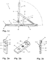
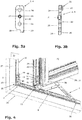
- FIGS. 1a, 1b . 1c shown fitting unit 1 together with one in the FIGS. 2a, 2b, 2c shown spacer 2 or together with a in the FIGS. 3a, 3b shown spacer 3 a fitting arrangement. 4
- the fitting unit 1 comprises a fixed-frame-side support bracket 5, a wing-side support bracket 6, and a scissor arrangement 7 provided between the fixed-frame-side support bracket 5 and the wing-side support bracket 6.
- the fixed-frame-side support bracket 5 has a storage leg 8 and a riveted to the storage leg 8 additional support leg angle 9. With the support leg 8 of the fixed frame side support bracket 5 also a guide contour 10 is riveted. Instead of riveting provided in the example shown case are between the items of the fixed frame side support bracket 5, for example, screw conceivable.
- wing guide element in the form of a guide projection 13 on the wing-side support bracket 6.
- the scissor assembly 7 comprises as scissor elements a Y-scissors 14 and a handlebar 15.
- the Y-scissors 17 is formed by scissor elements in the form of a long scissor arm 16 and a short scissor arm 17.
- the slider 18 engages with longitudinal edges extending in the direction of movement of the C-shaped bearing leg 8.
- brake screw 19 By operating a rotatably guided on the slider 18 brake screw 19 can be adjusted in a known manner, the movement resistance, which movement of the slider 18 along the storage leg 8 is opposite.
- the link 15 and the long scissor arm 16 of the scissor assembly 7 are rotatably connected by means of stationary pivot bearing.
- a stationary wing-side pivot bearing of the short scissor arm 17 is located on the long scissor arm 16 of the Y-scissors 14 between the end-side pivot bearings of the long scissor arm sixteenth
- spacer 2 has a substantially cuboidal base body 20, which on the in FIG. 2a upper end a projection 21 has.
- the projection 21 is provided on its downwardly facing side with a receiving slot 22 and with a semicircular recess 23.
- the width of the receiving slot 22 on the spacer 2 is dimensioned slightly smaller than the thickness of the additional support leg 9 of the fixed frame side support bracket 5 and the thickness of the additional support leg 12 of the wing-side support bracket 6. Due to the recess 23 on the projection 21 of the spacer 2 is a provided on the base body 20 of the spacer 2 cylindrical passage opening 24 for a in the FIGS.
- a further passage opening 25 for a fastening screw is provided on the main body 20 of the spacer 2 at a distance from the cylindrical passage opening 24.
- the passage opening 25 is deviating from the passage opening 24 formed as a slot.
- a passage opening 26 which is provided with an internal thread into which an adjusting element in the form of a set screw 27 engages.
- the set screw designed as a set screw 27 is provided at one longitudinal end with a hexagon socket, which serves as an engagement for an actuating tool.
- the spacer 3 according to the FIGS. 3a, 3b agrees constructively with the spacer 2 of the FIGS. 2a, 2b, 2c largely coincide. Notwithstanding the spacer 2, the contour of a lower corner is rounded at the spacer 3 and the base body 20 is provided to form a receptacle 28 with an extension 29.
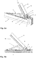
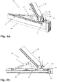
- FIGS. 4 to 7b the fitting assembly 4 is shown in the installed position.
- FIG. 4 the fitting arrangement 4 is arranged on a window 30 between a fixed frame 31 and a wing 32.
- the wing 32 opens to the outside.
- the wing-side support bracket 6 surrounds a wing corner 38 of the wing 32 at which a in FIG. 4 provided on the downwardly facing side of the wing 32 and therefore not recognizable horizontal first pogelfalz Chemistry 39 and a in FIG. 4 vertical second pogelfalz Chemistry 40 abut each other.
- Both the first Festrahmenfalz composition 36 and the second Festrahmenfalz composition 37 and the first diegelfalz Chemistry 39 and the second diegelfalz composition 40 are formed as groove-free flat Falzdon.
- the fixed-frame-side support bracket 5 rests with its support leg 8 on the first Festrahmenfalz Chemistry 36 and is bolted to the fixed frame 31 there. Another screw connection between the fixed-frame-side support bracket 5 and the fixed frame 31 is made on the additional support bracket leg 9 of the fixed-frame-side support bracket 5.
- the additional support angle leg 9 of the fixed-frame-side support bracket 5 is mounted via a spacer, in the illustrated example via the spacer 3, on the second fixed frame surface 37 of the fixed frame 31.
- the spacer 3 is attached to the additional support arm 9.
- the free end of the additional support leg 9 engages in the space provided on the spacer 3 receiving slot 22 a.
- the receiving slot 22 forms a positioning element and provides so far for a defined arrangement of the spacer 3 to the additional support bracket leg 9 of the fixed frame side support bracket. 5
- the thickness of the spacer 3 between the side facing the second Festrittenfalz Chemistry 37 side of the additional Tragwinkelschenkels 9 of the fixed frame side support bracket 5 on the one hand and the second Festrittenfalz materials 37 on the other hand corresponds to the extension of the supernatant with which the guide contour 10 pointing to the second Festrittenfalz Chemistry 37 toward Side of the additional support bracket leg 9 protrudes with respect to this to the second Festrittenfalz Chemistry 37 out.
- the spacer 3 on the additional support arm 9 for a planar support of the fixed frame side support bracket 5 on the fixed frame 31 provide.
- the supernatant of the guide contour 10 lies on the spacer 3 within the one-sided limited by the extension 29 receptacle 28th
- the wing-side support bracket 6 is connected to the wing 32 on the in FIG. 4 concealed storage leg 11 at the in FIG. 4 also not visible first pogelfalz Chemistry 39 and screwed on the additional support angle leg 12 on the second pogelfalz Chemistry 40.
- the storage leg 11 lies directly on the first pogelfalz Chemistry 39
- the additional support leg 12 is directly on the second pogelfalz Chemistry 40.
- Fastening elements in the form of fastening screws 46, 47 pass through openings 48, 49 on the additional support angle leg 12.
- An opening 50 on the additional support arm 12 is in the installation conditions according to FIG. 4 not used.
- the guide projection 13 on the support leg 11 of the wing-side support bracket 6 is on the side facing the fixed frame side guide contour 10 side of the additional support leg 12 and acts in the final phase of the closing movement of the wing 32 with the guide contour 10 such that the wing 32 collision-free in its closed position can reach the fixed frame 31.
- FIGS. 5a, 5b shown installation conditions on the window 30 are in accordance with the installation conditions FIG. 4 largely coincide. Deviating from FIG. 4 is in the FIGS. 5a, 5b only on the second diegelfalz Chemistry 40 extending in the circumferential direction of the wing 32 fitting part 51 is provided.
- the additional support arm 12 of the wing-side support bracket 6 has perpendicular to a in FIG. 5a As a result, the additional support leg 12 of the wing-side support bracket 6 can be mounted on the second pogelfalz Chemistry 40 on the Betschteilnut 51 on the outside resting.
- the fastening screws 46, 47 are screwed through the through-holes 48, 49 on the additional support leg 12 of the wing-side support bracket 6 in the groove bottom of the wing-side fitting part 51.
- Deviating from the FIGS. 4 and 5a, 5b show the FIGS. 6a, 6b and 7a, 7b a window 30 having a fixed frame 31, the second Festrahmenfalz Chemistry 37 is provided with a running in the circumferential direction of the fixed frame 31 Beschlagteilnut 53.
- the second diegelfalz Chemistry 40 of the wing 32 is in the FIGS. 6a, 6b formed as a groove-free flat surface and in the FIGS. 7a, 7b provided with a fitting part 51.
- the fitting part groove 53 on the second festrittenfalz Applications 37 receives the supernatant of the guide contour 10 at the fixed frame side support bracket 5.
- the additional support angle leg 9 of the fixed frame side support bracket 5 can create a flat surface directly on the second Festrittenfalz products 37.
- Wing side is the spacer 3 in the FIGS. 6a, 6b and 7a, 7b arranged on the side facing the second diegelfalz Chemistry 40 side of the additional support angle leg 12 of the wing-side support bracket 6.
- the spacer 3 in Figures 7a, 7b on the wing-side Betschteilnut 51 could be mounted externally resting after the Width of the spacer 3 is dimensioned perpendicular to the main plane 52 of the wing 32 larger than the opening width of the fitting part 51 on the second Festrahmenfalz Structure 40th
- the size of the seaming air that is, the gap width of the gap formed with the wing 32 closed between the second Festrahmenfalz Chemistry 37 and the second diegelfalz Chemistry 40, is in all in the FIGS. 4 to 7b shown installation conditions the same.
Landscapes
- Engineering & Computer Science (AREA)
- Mechanical Engineering (AREA)
- Door And Window Frames Mounted To Openings (AREA)
- Hinges (AREA)
- Civil Engineering (AREA)
- Structural Engineering (AREA)
- Securing Of Glass Panes Or The Like (AREA)
Applications Claiming Priority (1)
| Application Number | Priority Date | Filing Date | Title |
|---|---|---|---|
| DE102017207707.7A DE102017207707B3 (de) | 2017-05-08 | 2017-05-08 | Beschlaganordnung sowie Fenster oder Tür mit einer derartigen Beschlaganordnung |
Publications (1)
| Publication Number | Publication Date |
|---|---|
| EP3401483A1 true EP3401483A1 (fr) | 2018-11-14 |
Family
ID=62017236
Family Applications (1)
| Application Number | Title | Priority Date | Filing Date |
|---|---|---|---|
| EP18167753.5A Withdrawn EP3401483A1 (fr) | 2017-05-08 | 2018-04-17 | Ensemble ferrure ainsi que fenêtre, porte ou analogue comprenant un tel ensemble ferrure |
Country Status (4)
| Country | Link |
|---|---|
| US (1) | US10550618B2 (fr) |
| EP (1) | EP3401483A1 (fr) |
| CN (1) | CN108868418B (fr) |
| DE (1) | DE102017207707B3 (fr) |
Families Citing this family (4)
| Publication number | Priority date | Publication date | Assignee | Title |
|---|---|---|---|---|
| US11486179B1 (en) * | 2019-07-26 | 2022-11-01 | Andersen Corporation | Window hinge assembly and methods |
| GB2591992B (en) * | 2020-01-27 | 2024-10-09 | Garner Aluminium Extrusions Ltd | A hinge locator |
| EP4374040A1 (fr) * | 2021-07-20 | 2024-05-29 | Masterlab S.R.L. | Système de charnière dissimulée pour portes ou fenêtres |
| GB2644435A (en) * | 2024-08-30 | 2026-04-15 | G T Window Products Ltd | Anti-tamper device |
Citations (5)
| Publication number | Priority date | Publication date | Assignee | Title |
|---|---|---|---|---|
| GB2267932A (en) * | 1992-06-16 | 1993-12-22 | Dgs Hardware Ltd | Friction stay with spacer |
| GB2295200A (en) * | 1994-11-15 | 1996-05-22 | Cotswold Architect Prod | Stay hinges |
| GB2334547A (en) * | 1998-02-21 | 1999-08-25 | Cotswold Architect Prod | Window stays |
| GB2401648A (en) * | 2003-04-30 | 2004-11-17 | Cotswold Architect Prod | Jig for use with a stay |
| WO2016127512A1 (fr) * | 2015-02-10 | 2016-08-18 | 李增榜 | Charnière excentrique |
Family Cites Families (14)
| Publication number | Priority date | Publication date | Assignee | Title |
|---|---|---|---|---|
| US4833754A (en) * | 1988-09-26 | 1989-05-30 | Yang Wu N | Supporting bracket for windows |
| US5083344A (en) * | 1990-08-27 | 1992-01-28 | Truth Division Of Spx Corporation | Pivotal support bracket for a window hinge |
| US5711052A (en) * | 1996-11-04 | 1998-01-27 | Truth Hardware Corporation | Adjustable window hinge |
| US5898977A (en) * | 1997-09-25 | 1999-05-04 | Advantage Manufacturing Corp., Inc. | Non-handed in-line window supporting bracket |
| GB9929090D0 (en) * | 1999-12-09 | 2000-02-02 | Avocet Hardware Plc | Friction hinge for openable closure member |
| GB2388401B (en) * | 2002-05-10 | 2005-08-10 | Securistyle Ltd | A hinge |
| US7047600B2 (en) * | 2003-07-14 | 2006-05-23 | Advantage Manufacturing Corporation | Egress 4-bar hinge assembly |
| US7096539B2 (en) * | 2004-04-12 | 2006-08-29 | Advantage Manufacturing Corporation | Shim assembly for releasably engaging a hinge assembly |
| US7765741B2 (en) * | 2005-01-11 | 2010-08-03 | Pella Corporation | Movable light latch |
| ITBO20060809A1 (it) * | 2006-11-28 | 2008-05-29 | Gsg Int Spa | Gruppo cerniera per infissi a sporgere. |
| CA2858426C (fr) * | 2013-08-09 | 2017-10-10 | Caldwell Manufacturing Company North America, LLC | Ensemble charniere a tringlerie a barres multiples avec butee |
| CN104265102B (zh) * | 2014-09-01 | 2016-09-28 | 傅海 | 一种铰链 |
| DE102014226590A1 (de) | 2014-12-19 | 2016-06-23 | Eugen Notter Gmbh Beschlägefabrik | Beschlag für Fenster und Türen |
| PT3256675T (pt) * | 2015-02-11 | 2019-07-10 | Giesse Spa | Articulação para portas ou janelas |
-
2017
- 2017-05-08 DE DE102017207707.7A patent/DE102017207707B3/de not_active Expired - Fee Related
-
2018
- 2018-04-17 EP EP18167753.5A patent/EP3401483A1/fr not_active Withdrawn
- 2018-05-02 US US15/969,329 patent/US10550618B2/en active Active
- 2018-05-08 CN CN201810431513.6A patent/CN108868418B/zh not_active Expired - Fee Related
Patent Citations (5)
| Publication number | Priority date | Publication date | Assignee | Title |
|---|---|---|---|---|
| GB2267932A (en) * | 1992-06-16 | 1993-12-22 | Dgs Hardware Ltd | Friction stay with spacer |
| GB2295200A (en) * | 1994-11-15 | 1996-05-22 | Cotswold Architect Prod | Stay hinges |
| GB2334547A (en) * | 1998-02-21 | 1999-08-25 | Cotswold Architect Prod | Window stays |
| GB2401648A (en) * | 2003-04-30 | 2004-11-17 | Cotswold Architect Prod | Jig for use with a stay |
| WO2016127512A1 (fr) * | 2015-02-10 | 2016-08-18 | 李增榜 | Charnière excentrique |
Also Published As
| Publication number | Publication date |
|---|---|
| CN108868418A (zh) | 2018-11-23 |
| US20180320429A1 (en) | 2018-11-08 |
| CN108868418B (zh) | 2021-05-04 |
| US10550618B2 (en) | 2020-02-04 |
| DE102017207707B3 (de) | 2018-06-28 |
Similar Documents
| Publication | Publication Date | Title |
|---|---|---|
| EP2829679B1 (fr) | Ferrure pour l'appui d'un battant mobile contre une bordure fixe | |
| DE19709835B4 (de) | Fahrzeugtür | |
| EP2715021B1 (fr) | Scharnière | |
| EP3612700A1 (fr) | Panneau de meuble comprenant une ferrure de battant et corps de meuble et meuble comprenant un tel panneau de meuble | |
| DE202010015091U1 (de) | Möbelbeschlag und Möbel | |
| DE3872442T2 (de) | Drehbeschlag eines drehkippfluegels einer tuer eines fensters oder von aehnlichem. | |
| AT519903B1 (de) | Schiene zur Führung eines Schlittens einer Möbeltüre | |
| DE102017207707B3 (de) | Beschlaganordnung sowie Fenster oder Tür mit einer derartigen Beschlaganordnung | |
| EP2085553A2 (fr) | Ferrure pour palier d'angle | |
| DE102010012144B3 (de) | Türband für gefälzte Gebäudeabschlusstüren aus Holz | |
| EP0276678B1 (fr) | Ferrure pour porte ou fenêtre au moins pivotantes | |
| EP1788178B1 (fr) | Palier pour fenêtres, portes ou similaires | |
| EP2733290A2 (fr) | Agencement pour une armoire de compteur, une armoire de distribution, une armoire électrique ou un boîtier vide | |
| DE2242305A1 (de) | Anschlagfreundliches bauteilsystem fuer treibstangenbeschlaege | |
| DE102014226590A1 (de) | Beschlag für Fenster und Türen | |
| EP1614844A2 (fr) | Dispositif d'articulation | |
| EP3029227B2 (fr) | Ferrure dotée d'une plage de serrage réglable | |
| EP1200698A1 (fr) | Garniture limitant l'ouverture | |
| EP2882916B1 (fr) | Ouvre-porte pour une porte de bâtiment | |
| DE3249809C2 (de) | Beschlag zum schwenkbaren Befestigen einer Klappe an einem Schrank | |
| EP1757767B1 (fr) | Support d'angle | |
| EP1245771B1 (fr) | Charnière pour portes ou fenêtres | |
| DE19526016A1 (de) | Exzenterverstelleinrichtung für einen Beschlag für Fenster, Türen oder dergleichen | |
| EP0924375A1 (fr) | Ferrure de charnière pour une aíle à battement de recouvrement d'une fenêtre, porte ou similaire | |
| EP2685040B1 (fr) | Composant précontraint et procédé de fonctionnement pour une fenêtre ou une porte-fenêtre |
Legal Events
| Date | Code | Title | Description |
|---|---|---|---|
| PUAI | Public reference made under article 153(3) epc to a published international application that has entered the european phase |
Free format text: ORIGINAL CODE: 0009012 |
|
| STAA | Information on the status of an ep patent application or granted ep patent |
Free format text: STATUS: THE APPLICATION HAS BEEN PUBLISHED |
|
| AK | Designated contracting states |
Kind code of ref document: A1 Designated state(s): AL AT BE BG CH CY CZ DE DK EE ES FI FR GB GR HR HU IE IS IT LI LT LU LV MC MK MT NL NO PL PT RO RS SE SI SK SM TR |
|
| AX | Request for extension of the european patent |
Extension state: BA ME |
|
| STAA | Information on the status of an ep patent application or granted ep patent |
Free format text: STATUS: REQUEST FOR EXAMINATION WAS MADE |
|
| 17P | Request for examination filed |
Effective date: 20190513 |
|
| RBV | Designated contracting states (corrected) |
Designated state(s): AL AT BE BG CH CY CZ DE DK EE ES FI FR GB GR HR HU IE IS IT LI LT LU LV MC MK MT NL NO PL PT RO RS SE SI SK SM TR |
|
| RAP1 | Party data changed (applicant data changed or rights of an application transferred) |
Owner name: ROTO FRANK FENSTER- UND TUERTECHNOLOGIE GMBH |
|
| GRAP | Despatch of communication of intention to grant a patent |
Free format text: ORIGINAL CODE: EPIDOSNIGR1 |
|
| STAA | Information on the status of an ep patent application or granted ep patent |
Free format text: STATUS: GRANT OF PATENT IS INTENDED |
|
| INTG | Intention to grant announced |
Effective date: 20210311 |
|
| STAA | Information on the status of an ep patent application or granted ep patent |
Free format text: STATUS: THE APPLICATION HAS BEEN WITHDRAWN |
|
| 18W | Application withdrawn |
Effective date: 20210413 |