EP3401498B1 - Tragbares, vollelektrisches unterwasserantriebsmodul - Google Patents
Tragbares, vollelektrisches unterwasserantriebsmodul Download PDFInfo
- Publication number
- EP3401498B1 EP3401498B1 EP18163440.3A EP18163440A EP3401498B1 EP 3401498 B1 EP3401498 B1 EP 3401498B1 EP 18163440 A EP18163440 A EP 18163440A EP 3401498 B1 EP3401498 B1 EP 3401498B1
- Authority
- EP
- European Patent Office
- Prior art keywords
- subsea
- tool
- magnetic coupling
- drive module
- housing
- Prior art date
- Legal status (The legal status is an assumption and is not a legal conclusion. Google has not performed a legal analysis and makes no representation as to the accuracy of the status listed.)
- Active
Links
- 230000008878 coupling Effects 0.000 claims description 32
- 238000010168 coupling process Methods 0.000 claims description 32
- 238000005859 coupling reaction Methods 0.000 claims description 32
- 238000004891 communication Methods 0.000 claims description 18
- 238000004519 manufacturing process Methods 0.000 claims description 8
- 230000006870 function Effects 0.000 claims description 7
- 230000003287 optical effect Effects 0.000 claims description 7
- 238000004140 cleaning Methods 0.000 claims description 5
- 238000012544 monitoring process Methods 0.000 claims description 4
- XLYOFNOQVPJJNP-UHFFFAOYSA-N water Substances O XLYOFNOQVPJJNP-UHFFFAOYSA-N 0.000 claims description 4
- 238000002347 injection Methods 0.000 claims description 3
- 239000007924 injection Substances 0.000 claims description 3
- 238000005070 sampling Methods 0.000 claims description 3
- 239000000126 substance Substances 0.000 claims description 3
- 238000003032 molecular docking Methods 0.000 claims description 2
- 239000012530 fluid Substances 0.000 description 8
- 230000007246 mechanism Effects 0.000 description 5
- 230000008030 elimination Effects 0.000 description 3
- 238000003379 elimination reaction Methods 0.000 description 3
- 238000000034 method Methods 0.000 description 3
- 238000013500 data storage Methods 0.000 description 2
- 230000007613 environmental effect Effects 0.000 description 2
- 235000004507 Abies alba Nutrition 0.000 description 1
- 241000191291 Abies alba Species 0.000 description 1
- WHXSMMKQMYFTQS-UHFFFAOYSA-N Lithium Chemical compound [Li] WHXSMMKQMYFTQS-UHFFFAOYSA-N 0.000 description 1
- 230000000712 assembly Effects 0.000 description 1
- 238000000429 assembly Methods 0.000 description 1
- 230000008859 change Effects 0.000 description 1
- 239000000356 contaminant Substances 0.000 description 1
- 238000011161 development Methods 0.000 description 1
- 230000006872 improvement Effects 0.000 description 1
- 230000001939 inductive effect Effects 0.000 description 1
- 229910052744 lithium Inorganic materials 0.000 description 1
- 238000005259 measurement Methods 0.000 description 1
- 230000008569 process Effects 0.000 description 1
- 238000003860 storage Methods 0.000 description 1
Images

Classifications
-
- E—FIXED CONSTRUCTIONS
- E21—EARTH OR ROCK DRILLING; MINING
- E21B—EARTH OR ROCK DRILLING; OBTAINING OIL, GAS, WATER, SOLUBLE OR MELTABLE MATERIALS OR A SLURRY OF MINERALS FROM WELLS
- E21B41/00—Equipment or details not covered by groups E21B15/00 - E21B40/00
- E21B41/0007—Equipment or details not covered by groups E21B15/00 - E21B40/00 for underwater installations
-
- E—FIXED CONSTRUCTIONS
- E21—EARTH OR ROCK DRILLING; MINING
- E21B—EARTH OR ROCK DRILLING; OBTAINING OIL, GAS, WATER, SOLUBLE OR MELTABLE MATERIALS OR A SLURRY OF MINERALS FROM WELLS
- E21B33/00—Sealing or packing boreholes or wells
- E21B33/02—Surface sealing or packing
- E21B33/03—Well heads; Setting-up thereof
- E21B33/035—Well heads; Setting-up thereof specially adapted for underwater installations
- E21B33/037—Protective housings therefor
-
- E—FIXED CONSTRUCTIONS
- E21—EARTH OR ROCK DRILLING; MINING
- E21B—EARTH OR ROCK DRILLING; OBTAINING OIL, GAS, WATER, SOLUBLE OR MELTABLE MATERIALS OR A SLURRY OF MINERALS FROM WELLS
- E21B33/00—Sealing or packing boreholes or wells
- E21B33/02—Surface sealing or packing
- E21B33/03—Well heads; Setting-up thereof
- E21B33/035—Well heads; Setting-up thereof specially adapted for underwater installations
- E21B33/038—Connectors used on well heads, e.g. for connecting blow-out preventer and riser
- E21B33/0385—Connectors used on well heads, e.g. for connecting blow-out preventer and riser electrical connectors
-
- H—ELECTRICITY
- H02—GENERATION; CONVERSION OR DISTRIBUTION OF ELECTRIC POWER
- H02K—DYNAMO-ELECTRIC MACHINES
- H02K11/00—Structural association of dynamo-electric machines with electric components or with devices for shielding, monitoring or protection
- H02K11/30—Structural association with control circuits or drive circuits
- H02K11/33—Drive circuits, e.g. power electronics
-
- H—ELECTRICITY
- H02—GENERATION; CONVERSION OR DISTRIBUTION OF ELECTRIC POWER
- H02K—DYNAMO-ELECTRIC MACHINES
- H02K5/00—Casings; Enclosures; Supports
- H02K5/04—Casings or enclosures characterised by the shape, form or construction thereof
- H02K5/10—Casings or enclosures characterised by the shape, form or construction thereof with arrangements for protection from ingress, e.g. water or fingers
-
- H—ELECTRICITY
- H02—GENERATION; CONVERSION OR DISTRIBUTION OF ELECTRIC POWER
- H02K—DYNAMO-ELECTRIC MACHINES
- H02K5/00—Casings; Enclosures; Supports
- H02K5/04—Casings or enclosures characterised by the shape, form or construction thereof
- H02K5/12—Casings or enclosures characterised by the shape, form or construction thereof specially adapted for operating in liquid or gas
- H02K5/132—Submersible electric motors
-
- H—ELECTRICITY
- H02—GENERATION; CONVERSION OR DISTRIBUTION OF ELECTRIC POWER
- H02K—DYNAMO-ELECTRIC MACHINES
- H02K5/00—Casings; Enclosures; Supports
- H02K5/04—Casings or enclosures characterised by the shape, form or construction thereof
- H02K5/22—Auxiliary parts of casings not covered by groups H02K5/06-H02K5/20, e.g. shaped to form connection boxes or terminal boxes
- H02K5/225—Terminal boxes or connection arrangements
-
- H—ELECTRICITY
- H02—GENERATION; CONVERSION OR DISTRIBUTION OF ELECTRIC POWER
- H02K—DYNAMO-ELECTRIC MACHINES
- H02K7/00—Arrangements for handling mechanical energy structurally associated with dynamo-electric machines, e.g. structural association with mechanical driving motors or auxiliary dynamo-electric machines
- H02K7/10—Structural association with clutches, brakes, gears, pulleys or mechanical starters
- H02K7/11—Structural association with clutches, brakes, gears, pulleys or mechanical starters with dynamo-electric clutches
-
- H—ELECTRICITY
- H02—GENERATION; CONVERSION OR DISTRIBUTION OF ELECTRIC POWER
- H02K—DYNAMO-ELECTRIC MACHINES
- H02K7/00—Arrangements for handling mechanical energy structurally associated with dynamo-electric machines, e.g. structural association with mechanical driving motors or auxiliary dynamo-electric machines
- H02K7/10—Structural association with clutches, brakes, gears, pulleys or mechanical starters
- H02K7/116—Structural association with clutches, brakes, gears, pulleys or mechanical starters with gears
-
- E—FIXED CONSTRUCTIONS
- E21—EARTH OR ROCK DRILLING; MINING
- E21B—EARTH OR ROCK DRILLING; OBTAINING OIL, GAS, WATER, SOLUBLE OR MELTABLE MATERIALS OR A SLURRY OF MINERALS FROM WELLS
- E21B41/00—Equipment or details not covered by groups E21B15/00 - E21B40/00
- E21B41/04—Manipulators for underwater operations, e.g. temporarily connected to well heads
Definitions
- Disclosed embodiments relate generally to subsea equipment and more particularly to a portable, electrically powered, subsea drive module for powering subsea equipment.
- Subsea tools and production equipment commonly require a power source and drive mechanism to perform their intended function(s).
- Such tools and equipment generally employ hydraulic power and drive mechanisms, for example, provided by one or more hydraulic lines in communication with a subsea termination unit or other source of pressurized hydraulic fluid. While such hydraulic power and drive mechanisms are serviceable, there remains room for further improvement.
- EP 3087001 A1 discloses a method of providing power to a subsea equipment electrical system underwater.
- WO 2014/123425 A1 discloses a subsea valve for control of fluid.
- WO 2009/045110 A1 discloses an electrically driven subsea hydraulic pump unit.
- a subsea drive module according to claim 1 and a subsea tool assembly according to claim 5 are disclosed.
- the subsea tool may include a connector seal retrieval and replacement tool, a connector hub cleaning tool, a chemical injection valve assembly, a subsea sampling tool, a production flow module, a subsea intervention tool, a torque tool, or a vibration monitoring tool.
- the subsea drive module housing may optionally be sealed and pressure balanced internally for use in deep water subsea operations.
- the magnetic coupling may optionally be deployed in the housing and configured to engage the corresponding magnetic coupling in the subsea tool via a non-contact magnetic coupling.
- the magnetic coupling may optionally be deployed external to the housing and configured engage the corresponding magnetic coupling in the subsea tool via a contact magnetic coupling.
- the subsea drive module includes an electronics module in electronic communication with the subsea tool and/or with a surface command center.
- the disclosed subsea drive module embodiments may provide electrical and/or mechanical power to a subsea tool and therefore may obviate the need for hydraulic power and the use of hydraulic power lines.
- the elimination of hydraulics may advantageously provide for a clean, "zero leak" power source which in turn may reduce the environmental impact of subsea operations.
- the elimination of hydraulics may further reduce the size and complexity of subsea tools and simplify ROV tool delivery.
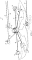
- FIG. 1 depicts an example subsea production system 10 (commonly referred to in the industry as a drill center) suitable for using various subsea drive modules disclosed herein.
- the system 10 may include a subsea manifold 20 deployed on the sea floor 15 in proximity to one or more subsea trees 22 (also referred to in the art as Christmas trees). As is known to those of ordinary skill each of the trees 22 is generally deployed above a corresponding subterranean well (not shown).
- fluid communication is provided between each of the trees 22 and the manifold 20 via a flowline jumper 40.
- the manifold 20 may also be in fluid communication with other subsea structures, such as one or more pipe line end terminals (PLETs) 24. Each of the PLETs is intended to provide fluid communication with a corresponding pipeline 28. Fluid communication is commonly provided between the PLETs 24 and the manifold 20 via corresponding flowline jumpers 40.
- PLETs pipe line end terminals
- FIG. 1 further depicts a subsea umbilical termination unit (SUTU) 30.
- the SUTU 30 may be in electrical and/or electronic communication with the surface via an umbilical line 32.
- Control lines 34 provide electrical and/or hydraulic communication between the various subsea structures 20 and 22 deployed on the sea floor 15 and the SUTU 30 (and therefore with the surface via the umbilical line 32).
- FIGS. 2A and 2B depict one example of a disclosed subsea drive module 100 connected with a subsea tool 200.
- FIG. 2A depicts a perspective view of the module 100 and tool 200 while FIG. 2B depicts a side view.
- the subsea tool 200 may be configured to service a subsea structure.
- the subsea structures may include substantially any subsea structure, for example, including a manifold, a tree, a PLET, a SOTU, a pipeline, or a jumper as described above with respect to FIG. 1 .
- the subsea tool 200 may likewise include substantially any suitable subsea tool, for example, a connector seal retrieval and replacement tool, a connector hub cleaning tool, chemical injection valves and assemblies, subsea sampling tools, production flow modules such as chokes and flow meters, intervention tools, torque tools, vibration monitoring tools and sensors, locks, overrides, or substantially any other tool that may be driven (or powered) by a remote electrical drive unit and delivered by a remotely operated vehicle (ROV) or autonomous underwater vehicle (AUV).
- ROV remotely operated vehicle
- AUV autonomous underwater vehicle
- subsea drive modules are intended to function as a "self-contained" unit thatprovides electrical and/or mechanical power (e.g., via a magnetic coupling or via an electrical connector) to subsea tool 200.
- the subsea drive modules may be configured to provide drive power to substantially any vertical or horizontal subsea tools such as vertical or horizontal connector tooling.
- the subsea drive module 100 is configured to provide drive power to the subsea tool 200.
- subsea drive module 100 may be magnetically coupled with a drive mechanism in the subsea tool 200 such that no direct mechanical connection is required (as described in more detail below with respect to FIGS. 3 and 4 ). In this way the subsea drive module 100 may further be sealed and pressure balanced internally for use in deep water subsea operations (e.g., to water depths exceeding 3000 m/ 10,000 feet).
- the subsea drive module 100 may include various electronic instrumentation (not depicted) for providing instrumentation and communications support to the subsea tool 200 and/or other subsea systems (not shown).
- electrical power e.g., DC battery power
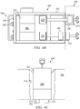
- FIGS. 3A and 3B depict example subsea drive modules 100 and 100' magnetically coupled with a subsea tool 200.
- subsea drive module 100 includes an electrical power supply 120 (such as a battery pack) and an electrical motor 130 deployed in a pressure balanced housing 110.
- the electrical motor 130 is configured to drive a magnetic coupling 140 (e.g., via drive shaft 135) which in turn may drive a corresponding magnetic coupling 240 deployed in the subsea tool 200 via a noncontact magnetic coupling.
- Rotation of the magnetic coupling 240 via electric motor 130 and magnetic coupling 140
- the depicted subsea drive module 100 further includes an ROV interface 150 having a plurality of switches 152 (such as non-contact magnetic switches) and optical indicators 154 (such as light emitting diodes).
- the optical indicators may be configured to indicate an operational status of the subsea drive module and/or the subsea tool while the switches may be configured to control the function of the module (e.g. to turn the motor 130 on/off and/or to change the motor rotation rate) such that an ROV may interact with the subsea drive module 100 and/or the subsea tool 200.
- subsea drive module 100' is similar to module 100 in that it includes an electrical power supply 120 such as a lithium battery pack and an electrical motor 130 deployed in a housing 110'.
- the electrical motor 130 is configured to drive a magnetic coupling 160 via gearing mechanism 145.
- the gears 145 may be configured for example to provide increased torque to the coupling 160.
- Subsea drive module 100' differs from drive module 100 ( FIG. 3A ) in that it includes an external magnetic coupling (external to housing 110') that is intended to contact and magnetically lock to a corresponding magnetic coupling 260 in the subsea tool 200'.
- Subsea drive module 100' may further include an ROV interface 150 (e.g., as described above with respect to FIG. 3 ) and an ROV handle 158 that may enable an ROV to transport the module 100'.
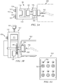
- FIGS. 4A-4C depict example subsea drive modules 300 and 300'.
- the drive module embodiment 300 depicted on FIGS. 4A and 4B is similar to module 100 ( FIG. 3A ) in that it is substantially horizontal and is configured for magnetic coupling with a subsea tool 200.
- Subsea drive module 300 includes an electrical power supply 320 such as a battery pack and first and second electrical motors 330 and 330' deployed in a housing 310 (e.g., a pressure balanced housing as described above).
- electrical motor 330 is configured to drive magnetic coupling 340 which is intended to contact and magnetically lock with corresponding magnetic coupling 270.
- Electrical motor 330' is configured to drive magnetic coupling 340' which is intended to drive corresponding magnetic coupling 270' via a noncontact magnetic drive.
- subsea drive module 300 further includes an electronics module 360 for providing electronic instrumentation and/or communications support to the subsea tool 200 and/or other subsea systems (not shown).
- drive module 300 may further include an ROV interface panel 350 having a plurality of switches 352 (such as non-contact magnetic switches) and optical indicators 354 (such as light emitting diodes).
- the drive module 300 may further include one or more ROV handles for transporting the module 300 in the subsea environment.
- FIG. 4C depicts a substantially vertical subsea drive module deployed in a corresponding cavity 210 in a subsea tool 200 (such as a subsea tree).
- Drive module 300' includes an electrical power supply 320 that provides power to electronics module 360.
- the electrical power supply also provides power to electrical connectors 370 that are configured to mate with and to provide electrical power to corresponding electrical connectors 280 in subsea tool 200.
- the subsea drive module may provide electrical power (e.g., DC battery power) to the subsea tool 200.
- the electrical connectors may include substantially any suitable electrical connectors suitable for use in subsea environments such as conventional "wetable" connectors or inductive connectors.
- Subsea drive module 300' may further include one or more ROV handles and an ROV interface panel having a plurality of switches and optical indicators (not shown on FIG. 4C ).
- the electronics module 360 depicted on FIG. 4 may include substantially any suitable electronic hardware, firmware, and/or software.
- the electronics module may include a communications interface configured to provide electronic communication between the subsea drive module and other subsea structures and/or a surface command center.
- the communications interface may be configured, for example, to provide two-way wireless or hard wired communication with the subsea tool, the surface command center, a subsea structure, and/or an ROV or AUV.
- the electronics module 360 may further include an electronic processor (not shown), such as a microprocessor or a microcontroller, and may also include processor-readable or computer-readable program code embodying logic, including instructions for controlling the function of the subsea drive module as well as the subsea tool.
- the electronics module may further include other controllable components, such as other sensors, data storage devices, power supplies, timers, and the like.
- the electronics module may further optionally include volatile or non-volatile memory or a data storage device for downhole storage of various sensor measurements and subsea tool performance metrics. The disclosed examples are expressly not limited in these regards.
- the disclosed subsea drive modules are intended to provide electrical and/or mechanical drive power to a subsea tool.
- the disclosed subsea drive modules are particularly advantageous when powering a deliverable subsea tool such as a connector seal retrieval and replacement tool, a connector hub cleaning tool, or substantially any other tool that may be delivered by a remotely operated vehicle (ROV) or autonomous underwater vehicle (AUV).
- ROV remotely operated vehicle
- AUV autonomous underwater vehicle
- the disclosed subsea drive modules may obviate the need to power such tools using hydraulics. The elimination of hydraulics may advantageously provide for a clean, "zero leak" power source which in turn may significantly reduce environmental impact.
- the disclosed subsea drive modules may further enable the development of "all-electric" electrically powered ROV tools such as prime movers, position monitoring instrumentation, and communications and operation logging tools. Such tools may be remotely controlled, monitored, and computerized via the disclosed subsea drive module.
Landscapes
- Engineering & Computer Science (AREA)
- Mining & Mineral Resources (AREA)
- Geology (AREA)
- Life Sciences & Earth Sciences (AREA)
- Power Engineering (AREA)
- Physics & Mathematics (AREA)
- Environmental & Geological Engineering (AREA)
- Fluid Mechanics (AREA)
- Geochemistry & Mineralogy (AREA)
- General Life Sciences & Earth Sciences (AREA)
- Microelectronics & Electronic Packaging (AREA)
- Connector Housings Or Holding Contact Members (AREA)
- Remote Sensing (AREA)
- Geophysics (AREA)
- Charge And Discharge Circuits For Batteries Or The Like (AREA)
- Details Of Connecting Devices For Male And Female Coupling (AREA)
Claims (6)
- Unterwasser-Antriebsmodul (300), das dazu ausgelegt ist, ein Unterwasserwerkzeug (200) anzutreiben, wobei das Unterwasser-Antriebsmodul (300) umfasst:ein Gehäuse (310), das für den Betrieb in einer Unterwasserumgebung ausgelegt ist;einen im Gehäuse (310) in Einsatzstellung gebrachten Elektromotor (330), wobei der Elektromotor (330) dazu ausgelegt ist, eine Magnetkopplung (340, 340') zu drehen, wobei die Magnetkopplung (340, 340') dazu bemessen und geformt ist, mit einer entsprechenden Magnetkopplung (270, 270') im Unterwasserwerkzeug (200) magnetisch in Eingriff zu treten; undeine im Gehäuse (310) in Einsatzstellung gebrachte elektrische Energieversorgung (320), wobei die elektrische Energieversorgung (320) elektrisch mit dem Motor (330, 330') verbunden ist und dazu ausgelegt ist, dem Motor (330, 330') elektrische Energie bereitzustellen, dadurch gekennzeichnet, dass das Unterwasser-Antriebsmodul (300) ferner umfasst:eine ROV-Schnittstelle (350) mit mehreren Schaltern (352), die dazu ausgelegt sind, die Funktion des Unterwasser-Antriebsmoduls (300) zu steuern, und optischen Anzeigegeräten (354) zum Anzeigen eines Betriebszustands des Unterwasser-Antriebsmoduls (300) und/oder des Unterwasserwerkzeugs (200); undein Elektronikmodul (360) in elektronischer Kommunikation mit dem Unterwasserwerkzeug (200) und mit einem obertägigen Befehlszentrum, das es ermöglicht Systemfunktionen wie Andockstelle und -positionierung über die Schalter (352) und optischen Anzeigegeräte (354) an der ROV-Schnittstelle (350) fernzuüberwachen und fernzusteuern.
- Unterwasser-Antriebsmodul (300) nach Anspruch 1, wobei das Gehäuse (310) für eine Verwendung im Tiefsee-Unterwasserbetrieb intern abgedichtet und druckentlastet ist.
- Unterwasser-Antriebsmodul (300) nach Anspruch 1, wobei:die Magnetkopplung (340') im Gehäuse (310) in Einsatzstellung gebracht und dazu ausgelegt ist, mit der entsprechenden Magnetkopplung (270') im Unterwasserwerkzeug (200) über eine kontaktlose Magnetkopplung in Eingriff zu treten; oderdie Magnetkopplung (340) außerhalb des Gehäuses (310) in Einsatzstellung gebracht und dazu ausgelegt ist, mit der entsprechenden Magnetkopplung (270') im Unterwasserwerkzeug (200) über eine Kontaktmagnetkopplung in Eingriff zu treten.
- Unterwasser-Antriebsmodul (300) nach Anspruch 1, wobei die elektrische Energieversorgung eine Batterie umfasst.
- Unterwasserwerkzeuganordnung, umfassend:ein Unterwasserwerkzeug (200); undein Unterwasser-Antriebsmodul (300) gemäß einem der vorhergehenden Ansprüche, das mit dem Unterwasserwerkzeug (200) verbunden ist und dazu ausgelegt ist, diesem Antriebsleistung bereitzustellen,wobei die Drehung der Magnetkopplung (340, 340') die entsprechende Magnetkopplung (270, 270') im Unterwasserwerkzeug (200) dreht und dadurch dem Unterwasserwerkzeug (200) die Antriebsleistung bereitstellt.
- Unterwasserwerkzeuganordnung nach Anspruch 5,
wobei das Unterwasserwerkzeug (200) ein Verbinderdichtungsabzieh- und -austauschwerkzeug, ein Verbindermuffenreinigungswerkzeug, eine chemische Injektionsventilanordnung, ein Unterwasser-Probenahmegerät, ein Produktionsdurchflussmodul, ein Unterwasser-Interventionswerkzeug, ein Drehmomentwerkzeug oder ein Vibrationsüberwachungsgerät ist.
Applications Claiming Priority (1)
| Application Number | Priority Date | Filing Date | Title |
|---|---|---|---|
| US15/465,810 US9926770B1 (en) | 2017-03-22 | 2017-03-22 | Portable all-electric subsea drive module |
Publications (3)
| Publication Number | Publication Date |
|---|---|
| EP3401498A2 EP3401498A2 (de) | 2018-11-14 |
| EP3401498A3 EP3401498A3 (de) | 2019-02-20 |
| EP3401498B1 true EP3401498B1 (de) | 2020-12-23 |
Family
ID=61633088
Family Applications (1)
| Application Number | Title | Priority Date | Filing Date |
|---|---|---|---|
| EP18163440.3A Active EP3401498B1 (de) | 2017-03-22 | 2018-03-22 | Tragbares, vollelektrisches unterwasserantriebsmodul |
Country Status (2)
| Country | Link |
|---|---|
| US (1) | US9926770B1 (de) |
| EP (1) | EP3401498B1 (de) |
Families Citing this family (4)
| Publication number | Priority date | Publication date | Assignee | Title |
|---|---|---|---|---|
| EP3740830B1 (de) * | 2018-01-18 | 2025-07-30 | Safe Marine Transfer, LLC | Intelligente elektrische unterwassersteuereinheit |
| NO20190107A1 (en) * | 2019-01-29 | 2020-07-30 | Icon Instr As | Pressure-equalized wireline apparatus |
| US20240084924A1 (en) * | 2022-09-09 | 2024-03-14 | Petróleo Brasileiro S.A. - Petrobras | Subsea termination device and method |
| GB2626726B (en) * | 2023-01-24 | 2025-07-23 | Baker Hughes Energy Technology UK Ltd | Subsea actuator coupling device |
Family Cites Families (15)
| Publication number | Priority date | Publication date | Assignee | Title |
|---|---|---|---|---|
| NO312376B1 (no) * | 2000-05-16 | 2002-04-29 | Kongsberg Offshore As | Fremgangsmåte og anordning for styring av ventiler av en undervannsinstallasjon |
| US7156169B2 (en) * | 2003-12-17 | 2007-01-02 | Fmc Technologies, Inc. | Electrically operated actuation tool for subsea completion system components |
| US7216714B2 (en) * | 2004-08-20 | 2007-05-15 | Oceaneering International, Inc. | Modular, distributed, ROV retrievable subsea control system, associated deepwater subsea blowout preventer stack configuration, and methods of use |
| WO2007139388A1 (en) * | 2006-05-26 | 2007-12-06 | Servo Electronics As | An apparatus for operating controllable installation means |
| NO20075029L (no) * | 2007-10-05 | 2009-04-06 | Multicontrol Hydraulics As | Elektrisk dervet hydraulisk pumpeenhet med akkumulatormodul for bruk til undervanns kontrollsystemer. |
| GB2457888C (en) * | 2008-02-26 | 2013-08-21 | Zetechtics Ltd | Subsea test apparatus, assembly and method |
| NO333503B1 (no) * | 2011-09-08 | 2013-06-24 | Capwell As | Vaierlineenhet |
| EP2579438A1 (de) * | 2011-10-06 | 2013-04-10 | Siemens Aktiengesellschaft | Leistungszelle für Tiefwasseranwendung |
| SG11201407176PA (en) * | 2012-05-02 | 2015-03-30 | Eaglepicher Technologies Llc | Reserve battery to provide power for subsea applications |
| US9222555B2 (en) * | 2012-08-06 | 2015-12-29 | Cameron International Corporation | Linear actuator |
| NO335707B1 (no) * | 2013-02-06 | 2015-01-26 | Aker Subsea As | Undervannsventil |
| KR102307568B1 (ko) * | 2013-08-15 | 2021-10-06 | 트랜스오션 이노베이션 랩스 리미티드 | 해저 펌핑 장치 및 관련 방법 |
| GB2521626C (en) * | 2013-12-23 | 2019-10-30 | Subsea 7 Ltd | Transmission of power underwater |
| US20150267704A1 (en) * | 2014-03-18 | 2015-09-24 | Fuglesangs Subsea As | Sealed magnetic drive for rotary machine |
| US9964113B2 (en) * | 2015-05-11 | 2018-05-08 | Fuglesangs Subsea As | Omnirise hydromag “variable speed magnetic coupling system for subsea pumps” |
-
2017
- 2017-03-22 US US15/465,810 patent/US9926770B1/en active Active
-
2018
- 2018-03-22 EP EP18163440.3A patent/EP3401498B1/de active Active
Non-Patent Citations (1)
| Title |
|---|
| None * |
Also Published As
| Publication number | Publication date |
|---|---|
| EP3401498A3 (de) | 2019-02-20 |
| US9926770B1 (en) | 2018-03-27 |
| EP3401498A2 (de) | 2018-11-14 |
Similar Documents
| Publication | Publication Date | Title |
|---|---|---|
| EP3401498B1 (de) | Tragbares, vollelektrisches unterwasserantriebsmodul | |
| US20220250256A1 (en) | Submersible remote operated vehicle tool interchange | |
| EP3676476B1 (de) | Steuerung einer unterwasservorrichtung | |
| CN103228861A (zh) | 具有无线单元的井下系统 | |
| EP3426880B1 (de) | Elektrisches unterwasser-stellgliedsystem | |
| US20170204704A1 (en) | Remotely-Operated Subsea Control Module | |
| US9732879B2 (en) | Sensor assembly for monitoring a fluid extraction component | |
| US10605038B2 (en) | Latch assembly using on-board miniature hydraulics for RCD applications | |
| CN103459763A (zh) | 模块化井下工具 | |
| WO2015001377A1 (en) | Subsea system comprising a crawler | |
| US20230111367A1 (en) | Downhole intervention and completion drone and methods of use | |
| EP3482029A1 (de) | Elektrische bohr- und produktionssysteme und -verfahren | |
| WO2011059925A2 (en) | Deploying an electrically-activated tool into a subsea well | |
| US20160258653A1 (en) | Subsea ROV-Mounted Hot Water Injection Skid | |
| WO2016000057A1 (pt) | Sistema de atuação compartilhada | |
| US20230258279A1 (en) | Multi valve electrical actuator | |
| WO2017031564A1 (pt) | Sistema submarino gerador de potência elétrica | |
| CN111386382B (zh) | 在海底油井中插入装置的方法、从海底油井中移除装置的方法、以及用于在海底油井中插入和移除装置的系统 | |
| KR101455654B1 (ko) | 스러스터 캐니스터의 빌지 흡입 시스템 | |
| US12577844B2 (en) | Electrically actuated access module systems and methods | |
| CN108799689A (zh) | 一种水下开孔装置及方法 | |
| Theobald | SPARCS autonomous control system | |
| BR112020002264B1 (pt) | Sistema de controle auxiliar para controlar equipamento submarino e método para controlar equipamento submarino |
Legal Events
| Date | Code | Title | Description |
|---|---|---|---|
| PUAI | Public reference made under article 153(3) epc to a published international application that has entered the european phase |
Free format text: ORIGINAL CODE: 0009012 |
|
| STAA | Information on the status of an ep patent application or granted ep patent |
Free format text: STATUS: THE APPLICATION HAS BEEN PUBLISHED |
|
| AK | Designated contracting states |
Kind code of ref document: A2 Designated state(s): AL AT BE BG CH CY CZ DE DK EE ES FI FR GB GR HR HU IE IS IT LI LT LU LV MC MK MT NL NO PL PT RO RS SE SI SK SM TR |
|
| AX | Request for extension of the european patent |
Extension state: BA ME |
|
| PUAL | Search report despatched |
Free format text: ORIGINAL CODE: 0009013 |
|
| AK | Designated contracting states |
Kind code of ref document: A3 Designated state(s): AL AT BE BG CH CY CZ DE DK EE ES FI FR GB GR HR HU IE IS IT LI LT LU LV MC MK MT NL NO PL PT RO RS SE SI SK SM TR |
|
| AX | Request for extension of the european patent |
Extension state: BA ME |
|
| RIC1 | Information provided on ipc code assigned before grant |
Ipc: H02K 11/33 20160101ALI20190111BHEP Ipc: F16K 31/04 20060101ALI20190111BHEP Ipc: H02K 7/116 20060101ALI20190111BHEP Ipc: H02K 7/11 20060101ALI20190111BHEP Ipc: E21B 33/035 20060101AFI20190111BHEP Ipc: H02K 5/22 20060101ALI20190111BHEP Ipc: E21B 33/038 20060101ALI20190111BHEP Ipc: E21B 33/037 20060101ALI20190111BHEP Ipc: E21B 41/04 20060101ALI20190111BHEP Ipc: H02K 5/132 20060101ALI20190111BHEP Ipc: E21B 41/00 20060101ALI20190111BHEP |
|
| STAA | Information on the status of an ep patent application or granted ep patent |
Free format text: STATUS: REQUEST FOR EXAMINATION WAS MADE |
|
| 17P | Request for examination filed |
Effective date: 20190820 |
|
| RBV | Designated contracting states (corrected) |
Designated state(s): AL AT BE BG CH CY CZ DE DK EE ES FI FR GB GR HR HU IE IS IT LI LT LU LV MC MK MT NL NO PL PT RO RS SE SI SK SM TR |
|
| GRAP | Despatch of communication of intention to grant a patent |
Free format text: ORIGINAL CODE: EPIDOSNIGR1 |
|
| STAA | Information on the status of an ep patent application or granted ep patent |
Free format text: STATUS: GRANT OF PATENT IS INTENDED |
|
| INTG | Intention to grant announced |
Effective date: 20200721 |
|
| GRAS | Grant fee paid |
Free format text: ORIGINAL CODE: EPIDOSNIGR3 |
|
| GRAA | (expected) grant |
Free format text: ORIGINAL CODE: 0009210 |
|
| STAA | Information on the status of an ep patent application or granted ep patent |
Free format text: STATUS: THE PATENT HAS BEEN GRANTED |
|
| AK | Designated contracting states |
Kind code of ref document: B1 Designated state(s): AL AT BE BG CH CY CZ DE DK EE ES FI FR GB GR HR HU IE IS IT LI LT LU LV MC MK MT NL NO PL PT RO RS SE SI SK SM TR |
|
| REG | Reference to a national code |
Ref country code: GB Ref legal event code: FG4D |
|
| REG | Reference to a national code |
Ref country code: DE Ref legal event code: R096 Ref document number: 602018010972 Country of ref document: DE |
|
| REG | Reference to a national code |
Ref country code: AT Ref legal event code: REF Ref document number: 1347893 Country of ref document: AT Kind code of ref document: T Effective date: 20210115 |
|
| REG | Reference to a national code |
Ref country code: IE Ref legal event code: FG4D |
|
| PG25 | Lapsed in a contracting state [announced via postgrant information from national office to epo] |
Ref country code: GR Free format text: LAPSE BECAUSE OF FAILURE TO SUBMIT A TRANSLATION OF THE DESCRIPTION OR TO PAY THE FEE WITHIN THE PRESCRIBED TIME-LIMIT Effective date: 20210324 Ref country code: RS Free format text: LAPSE BECAUSE OF FAILURE TO SUBMIT A TRANSLATION OF THE DESCRIPTION OR TO PAY THE FEE WITHIN THE PRESCRIBED TIME-LIMIT Effective date: 20201223 Ref country code: FI Free format text: LAPSE BECAUSE OF FAILURE TO SUBMIT A TRANSLATION OF THE DESCRIPTION OR TO PAY THE FEE WITHIN THE PRESCRIBED TIME-LIMIT Effective date: 20201223 |
|
| REG | Reference to a national code |
Ref country code: AT Ref legal event code: MK05 Ref document number: 1347893 Country of ref document: AT Kind code of ref document: T Effective date: 20201223 |
|
| REG | Reference to a national code |
Ref country code: NL Ref legal event code: MP Effective date: 20201223 |
|
| PG25 | Lapsed in a contracting state [announced via postgrant information from national office to epo] |
Ref country code: BG Free format text: LAPSE BECAUSE OF FAILURE TO SUBMIT A TRANSLATION OF THE DESCRIPTION OR TO PAY THE FEE WITHIN THE PRESCRIBED TIME-LIMIT Effective date: 20210323 Ref country code: LV Free format text: LAPSE BECAUSE OF FAILURE TO SUBMIT A TRANSLATION OF THE DESCRIPTION OR TO PAY THE FEE WITHIN THE PRESCRIBED TIME-LIMIT Effective date: 20201223 Ref country code: SE Free format text: LAPSE BECAUSE OF FAILURE TO SUBMIT A TRANSLATION OF THE DESCRIPTION OR TO PAY THE FEE WITHIN THE PRESCRIBED TIME-LIMIT Effective date: 20201223 |
|
| REG | Reference to a national code |
Ref country code: NO Ref legal event code: T2 Effective date: 20201223 |
|
| PG25 | Lapsed in a contracting state [announced via postgrant information from national office to epo] |
Ref country code: NL Free format text: LAPSE BECAUSE OF FAILURE TO SUBMIT A TRANSLATION OF THE DESCRIPTION OR TO PAY THE FEE WITHIN THE PRESCRIBED TIME-LIMIT Effective date: 20201223 Ref country code: HR Free format text: LAPSE BECAUSE OF FAILURE TO SUBMIT A TRANSLATION OF THE DESCRIPTION OR TO PAY THE FEE WITHIN THE PRESCRIBED TIME-LIMIT Effective date: 20201223 |
|
| REG | Reference to a national code |
Ref country code: LT Ref legal event code: MG9D |
|
| PG25 | Lapsed in a contracting state [announced via postgrant information from national office to epo] |
Ref country code: LT Free format text: LAPSE BECAUSE OF FAILURE TO SUBMIT A TRANSLATION OF THE DESCRIPTION OR TO PAY THE FEE WITHIN THE PRESCRIBED TIME-LIMIT Effective date: 20201223 Ref country code: RO Free format text: LAPSE BECAUSE OF FAILURE TO SUBMIT A TRANSLATION OF THE DESCRIPTION OR TO PAY THE FEE WITHIN THE PRESCRIBED TIME-LIMIT Effective date: 20201223 Ref country code: PT Free format text: LAPSE BECAUSE OF FAILURE TO SUBMIT A TRANSLATION OF THE DESCRIPTION OR TO PAY THE FEE WITHIN THE PRESCRIBED TIME-LIMIT Effective date: 20210423 Ref country code: SK Free format text: LAPSE BECAUSE OF FAILURE TO SUBMIT A TRANSLATION OF THE DESCRIPTION OR TO PAY THE FEE WITHIN THE PRESCRIBED TIME-LIMIT Effective date: 20201223 Ref country code: CZ Free format text: LAPSE BECAUSE OF FAILURE TO SUBMIT A TRANSLATION OF THE DESCRIPTION OR TO PAY THE FEE WITHIN THE PRESCRIBED TIME-LIMIT Effective date: 20201223 Ref country code: EE Free format text: LAPSE BECAUSE OF FAILURE TO SUBMIT A TRANSLATION OF THE DESCRIPTION OR TO PAY THE FEE WITHIN THE PRESCRIBED TIME-LIMIT Effective date: 20201223 Ref country code: SM Free format text: LAPSE BECAUSE OF FAILURE TO SUBMIT A TRANSLATION OF THE DESCRIPTION OR TO PAY THE FEE WITHIN THE PRESCRIBED TIME-LIMIT Effective date: 20201223 |
|
| PG25 | Lapsed in a contracting state [announced via postgrant information from national office to epo] |
Ref country code: AT Free format text: LAPSE BECAUSE OF FAILURE TO SUBMIT A TRANSLATION OF THE DESCRIPTION OR TO PAY THE FEE WITHIN THE PRESCRIBED TIME-LIMIT Effective date: 20201223 Ref country code: PL Free format text: LAPSE BECAUSE OF FAILURE TO SUBMIT A TRANSLATION OF THE DESCRIPTION OR TO PAY THE FEE WITHIN THE PRESCRIBED TIME-LIMIT Effective date: 20201223 |
|
| REG | Reference to a national code |
Ref country code: DE Ref legal event code: R097 Ref document number: 602018010972 Country of ref document: DE |
|
| PG25 | Lapsed in a contracting state [announced via postgrant information from national office to epo] |
Ref country code: IS Free format text: LAPSE BECAUSE OF FAILURE TO SUBMIT A TRANSLATION OF THE DESCRIPTION OR TO PAY THE FEE WITHIN THE PRESCRIBED TIME-LIMIT Effective date: 20210423 |
|
| PG25 | Lapsed in a contracting state [announced via postgrant information from national office to epo] |
Ref country code: AL Free format text: LAPSE BECAUSE OF FAILURE TO SUBMIT A TRANSLATION OF THE DESCRIPTION OR TO PAY THE FEE WITHIN THE PRESCRIBED TIME-LIMIT Effective date: 20201223 Ref country code: MC Free format text: LAPSE BECAUSE OF FAILURE TO SUBMIT A TRANSLATION OF THE DESCRIPTION OR TO PAY THE FEE WITHIN THE PRESCRIBED TIME-LIMIT Effective date: 20201223 Ref country code: IT Free format text: LAPSE BECAUSE OF FAILURE TO SUBMIT A TRANSLATION OF THE DESCRIPTION OR TO PAY THE FEE WITHIN THE PRESCRIBED TIME-LIMIT Effective date: 20201223 |
|
| PLBE | No opposition filed within time limit |
Free format text: ORIGINAL CODE: 0009261 |
|
| REG | Reference to a national code |
Ref country code: CH Ref legal event code: PL |
|
| STAA | Information on the status of an ep patent application or granted ep patent |
Free format text: STATUS: NO OPPOSITION FILED WITHIN TIME LIMIT |
|
| PG25 | Lapsed in a contracting state [announced via postgrant information from national office to epo] |
Ref country code: DK Free format text: LAPSE BECAUSE OF FAILURE TO SUBMIT A TRANSLATION OF THE DESCRIPTION OR TO PAY THE FEE WITHIN THE PRESCRIBED TIME-LIMIT Effective date: 20201223 |
|
| 26N | No opposition filed |
Effective date: 20210924 |
|
| REG | Reference to a national code |
Ref country code: BE Ref legal event code: MM Effective date: 20210331 |
|
| PG25 | Lapsed in a contracting state [announced via postgrant information from national office to epo] |
Ref country code: FR Free format text: LAPSE BECAUSE OF NON-PAYMENT OF DUE FEES Effective date: 20210331 Ref country code: ES Free format text: LAPSE BECAUSE OF FAILURE TO SUBMIT A TRANSLATION OF THE DESCRIPTION OR TO PAY THE FEE WITHIN THE PRESCRIBED TIME-LIMIT Effective date: 20201223 Ref country code: CH Free format text: LAPSE BECAUSE OF NON-PAYMENT OF DUE FEES Effective date: 20210331 Ref country code: LI Free format text: LAPSE BECAUSE OF NON-PAYMENT OF DUE FEES Effective date: 20210331 Ref country code: IE Free format text: LAPSE BECAUSE OF NON-PAYMENT OF DUE FEES Effective date: 20210322 Ref country code: LU Free format text: LAPSE BECAUSE OF NON-PAYMENT OF DUE FEES Effective date: 20210322 |
|
| PG25 | Lapsed in a contracting state [announced via postgrant information from national office to epo] |
Ref country code: SI Free format text: LAPSE BECAUSE OF FAILURE TO SUBMIT A TRANSLATION OF THE DESCRIPTION OR TO PAY THE FEE WITHIN THE PRESCRIBED TIME-LIMIT Effective date: 20201223 |
|
| PG25 | Lapsed in a contracting state [announced via postgrant information from national office to epo] |
Ref country code: IS Free format text: LAPSE BECAUSE OF FAILURE TO SUBMIT A TRANSLATION OF THE DESCRIPTION OR TO PAY THE FEE WITHIN THE PRESCRIBED TIME-LIMIT Effective date: 20210423 |
|
| PG25 | Lapsed in a contracting state [announced via postgrant information from national office to epo] |
Ref country code: BE Free format text: LAPSE BECAUSE OF NON-PAYMENT OF DUE FEES Effective date: 20210331 |
|
| PG25 | Lapsed in a contracting state [announced via postgrant information from national office to epo] |
Ref country code: CY Free format text: LAPSE BECAUSE OF FAILURE TO SUBMIT A TRANSLATION OF THE DESCRIPTION OR TO PAY THE FEE WITHIN THE PRESCRIBED TIME-LIMIT Effective date: 20201223 |
|
| PG25 | Lapsed in a contracting state [announced via postgrant information from national office to epo] |
Ref country code: HU Free format text: LAPSE BECAUSE OF FAILURE TO SUBMIT A TRANSLATION OF THE DESCRIPTION OR TO PAY THE FEE WITHIN THE PRESCRIBED TIME-LIMIT; INVALID AB INITIO Effective date: 20180322 |
|
| P01 | Opt-out of the competence of the unified patent court (upc) registered |
Effective date: 20231212 |
|
| PG25 | Lapsed in a contracting state [announced via postgrant information from national office to epo] |
Ref country code: MK Free format text: LAPSE BECAUSE OF FAILURE TO SUBMIT A TRANSLATION OF THE DESCRIPTION OR TO PAY THE FEE WITHIN THE PRESCRIBED TIME-LIMIT Effective date: 20201223 |
|
| PG25 | Lapsed in a contracting state [announced via postgrant information from national office to epo] |
Ref country code: TR Free format text: LAPSE BECAUSE OF FAILURE TO SUBMIT A TRANSLATION OF THE DESCRIPTION OR TO PAY THE FEE WITHIN THE PRESCRIBED TIME-LIMIT Effective date: 20201223 |
|
| PG25 | Lapsed in a contracting state [announced via postgrant information from national office to epo] |
Ref country code: MT Free format text: LAPSE BECAUSE OF FAILURE TO SUBMIT A TRANSLATION OF THE DESCRIPTION OR TO PAY THE FEE WITHIN THE PRESCRIBED TIME-LIMIT Effective date: 20201223 |
|
| PGFP | Annual fee paid to national office [announced via postgrant information from national office to epo] |
Ref country code: DE Payment date: 20241231 Year of fee payment: 8 |
|
| PGFP | Annual fee paid to national office [announced via postgrant information from national office to epo] |
Ref country code: NO Payment date: 20250312 Year of fee payment: 8 |
|
| PGFP | Annual fee paid to national office [announced via postgrant information from national office to epo] |
Ref country code: GB Payment date: 20250102 Year of fee payment: 8 |