EP3401582A1 - Élément d'étanchéité et kit de protection incendie comprenant un élément d'étanchéité - Google Patents
Élément d'étanchéité et kit de protection incendie comprenant un élément d'étanchéité Download PDFInfo
- Publication number
- EP3401582A1 EP3401582A1 EP17170388.7A EP17170388A EP3401582A1 EP 3401582 A1 EP3401582 A1 EP 3401582A1 EP 17170388 A EP17170388 A EP 17170388A EP 3401582 A1 EP3401582 A1 EP 3401582A1
- Authority
- EP
- European Patent Office
- Prior art keywords
- sealing element
- sealing
- filling aid
- einfüllausnehmung
- filling
- Prior art date
- Legal status (The legal status is an assumption and is not a legal conclusion. Google has not performed a legal analysis and makes no representation as to the accuracy of the status listed.)
- Withdrawn
Links
- 238000007789 sealing Methods 0.000 title claims abstract description 149
- 230000002093 peripheral effect Effects 0.000 claims abstract description 13
- 239000000463 material Substances 0.000 claims description 6
- 238000003780 insertion Methods 0.000 claims description 4
- 230000037431 insertion Effects 0.000 claims description 4
- 239000003063 flame retardant Substances 0.000 claims description 3
- 239000003566 sealing material Substances 0.000 description 30
- 239000007788 liquid Substances 0.000 description 14
- 239000006260 foam Substances 0.000 description 6
- 239000011248 coating agent Substances 0.000 description 2
- 238000000576 coating method Methods 0.000 description 2
- 238000001035 drying Methods 0.000 description 2
- 238000009434 installation Methods 0.000 description 2
- 239000000565 sealant Substances 0.000 description 2
- 239000004809 Teflon Substances 0.000 description 1
- 229920006362 Teflon® Polymers 0.000 description 1
- 238000010521 absorption reaction Methods 0.000 description 1
- 230000001154 acute effect Effects 0.000 description 1
- 239000003795 chemical substances by application Substances 0.000 description 1
- 238000005429 filling process Methods 0.000 description 1
- 238000009415 formwork Methods 0.000 description 1
- 239000011440 grout Substances 0.000 description 1
- 239000011810 insulating material Substances 0.000 description 1
- 238000004519 manufacturing process Methods 0.000 description 1
- 230000035515 penetration Effects 0.000 description 1
- 239000004033 plastic Substances 0.000 description 1
- 238000004382 potting Methods 0.000 description 1
- 238000003825 pressing Methods 0.000 description 1
- 239000004447 silicone coating Substances 0.000 description 1
- 229920001187 thermosetting polymer Polymers 0.000 description 1
- XLYOFNOQVPJJNP-UHFFFAOYSA-N water Substances O XLYOFNOQVPJJNP-UHFFFAOYSA-N 0.000 description 1
- 238000004078 waterproofing Methods 0.000 description 1
Images



Classifications
-
- H—ELECTRICITY
- H02—GENERATION; CONVERSION OR DISTRIBUTION OF ELECTRIC POWER
- H02G—INSTALLATION OF ELECTRIC CABLES OR LINES, OR OF COMBINED OPTICAL AND ELECTRIC CABLES OR LINES
- H02G3/00—Installations of electric cables or lines or protective tubing therefor in or on buildings, equivalent structures or vehicles
- H02G3/02—Details
- H02G3/04—Protective tubing or conduits, e.g. cable ladders or cable troughs
- H02G3/0406—Details thereof
- H02G3/0412—Heat or fire protective means
-
- F—MECHANICAL ENGINEERING; LIGHTING; HEATING; WEAPONS; BLASTING
- F16—ENGINEERING ELEMENTS AND UNITS; GENERAL MEASURES FOR PRODUCING AND MAINTAINING EFFECTIVE FUNCTIONING OF MACHINES OR INSTALLATIONS; THERMAL INSULATION IN GENERAL
- F16L—PIPES; JOINTS OR FITTINGS FOR PIPES; SUPPORTS FOR PIPES, CABLES OR PROTECTIVE TUBING; MEANS FOR THERMAL INSULATION IN GENERAL
- F16L5/00—Devices for use where pipes, cables or protective tubing pass through walls or partitions
- F16L5/02—Sealing
- F16L5/04—Sealing to form a firebreak device
-
- H—ELECTRICITY
- H02—GENERATION; CONVERSION OR DISTRIBUTION OF ELECTRIC POWER
- H02G—INSTALLATION OF ELECTRIC CABLES OR LINES, OR OF COMBINED OPTICAL AND ELECTRIC CABLES OR LINES
- H02G3/00—Installations of electric cables or lines or protective tubing therefor in or on buildings, equivalent structures or vehicles
- H02G3/22—Installations of cables or lines through walls, floors or ceilings, e.g. into buildings
-
- A—HUMAN NECESSITIES
- A62—LIFE-SAVING; FIRE-FIGHTING
- A62C—FIRE-FIGHTING
- A62C3/00—Fire prevention, containment or extinguishing specially adapted for particular objects or places
- A62C3/16—Fire prevention, containment or extinguishing specially adapted for particular objects or places in electrical installations, e.g. cableways
-
- E—FIXED CONSTRUCTIONS
- E04—BUILDING
- E04B—GENERAL BUILDING CONSTRUCTIONS; WALLS, e.g. PARTITIONS; ROOFS; FLOORS; CEILINGS; INSULATION OR OTHER PROTECTION OF BUILDINGS
- E04B1/00—Constructions in general; Structures which are not restricted either to walls, e.g. partitions, or floors or ceilings or roofs
- E04B1/62—Insulation or other protection; Elements or use of specified material therefor
- E04B1/92—Protection against other undesired influences or dangers
- E04B1/94—Protection against other undesired influences or dangers against fire
- E04B1/948—Fire-proof sealings or joints
Definitions
- the present invention relates to a sealing element and a fire protection set with a sealing element for sealing wall or ceiling openings.
- a sealing element for sealing wall or ceiling openings in particular wall openings, having at least one Einphilllaus fundamentalung, which is arranged and formed on a peripheral edge of the sealing element to allow filling of a cavity located behind the sealing element when the sealing element is mounted in a wall opening, or to facilitate when the sealing element is mounted in a ceiling opening.
- Such a sealing element has the advantage that a sealing of a breakthrough is made possible without previously an additional frame system or sealing tapes must be installed in the breakthrough.
- the sealing element can be quickly and easily inserted with a handle in the breakthrough and serves both as a fire protection element and as a formwork aid.
- the Ein spallaus brieflyung is preferably formed semicircular. This has the advantage that separate filling aids, such as funnels or pipes, are particularly easy to insert into the Ein colllaus Principleung and close them during a filling process with a liquid sealing material. In particular, it can be avoided that a not yet cured sealing material between the filling aid and the sealing element can leak. Nevertheless, for example, square Ein spallausström are not excluded.
- the sealing element may have a filling aid, which adjoins the Ein Schollaus originallyung.
- the filling aid is formed integrally with the sealing element. This provides the advantage that the user no longer requires a separate filling aid. The labor involved in sealing a breakthrough is significantly reduced in this way.
- the filling aid can be designed as a groove.
- the profile of the filling aid can be adapted to the shape of the Ein Schollaus originallyung.
- the filling aid has a semicircular profile.
- a liquid sealing material can thus be poured anywhere on the filling aid and in the filling aid to the filling and through this through behind the sealing element into a breakthrough, when the sealing element is mounted in a wall or a ceiling.
- the sealing element has a main body which is planar, wherein the filling aid forms an obtuse angle with the main body.
- the main body is placed in a mounting of the sealing element in the opening. Due to the planar design of the main body of this completes in the assembled state just with a wall.
- the main body has in a plan view, for example, a substantially round outer contour.
- the main body may also have an angular or otherwise shaped outer contour, depending on the breakthrough for which the sealing element is to be suitable.
- the main body is formed as a disc.
- the filling aid includes an obtuse angle with the main body has the advantage that when the sealing element is mounted in a vertical wall, the filling aid extends obliquely upward in a direction away from the wall.
- the filling aid runs, as it were, like a chute towards the filling recess, so that liquid sealing material flows by itself via the filling aid through the filling recess.
- the sealing element must be inserted in the correct orientation in a breakthrough, so that the filling aid in the assembled state of the sealing element facing upward.
- the filling aid may enclose an acute angle with the main body of the sealing element. This is advantageous if the sealing element is to be suitable for sealing a breakthrough in the ground. In this case, the sealing element can be used in any orientation in the breakthrough. The filling aid then runs, for example, away from the filling recess in an upward direction and towards the center of the sealing element.
- the filling aid extends in a direction parallel to a main expansion surface of the sealing element via a peripheral edge of the Main body away.
- the main expansion surface is the surface in which the main body of the sealing element extends in a plan view of the sealing element.
- the sealing element has thereby in a plan view the shape of a keyhole.
- the filling aid extends upward beyond the opening when the sealing element is mounted in the correct orientation in a breakthrough of a vertical wall.
- the breakthrough can advantageously be filled up to its edge and a little way beyond with liquid sealing material without the sealing material can leak. This ensures that the breakthrough is completely filled with sealing material without an air gap remaining in the opening.
- the filling aid can optionally be cut to obtain the most level possible wall surface.
- an insertion be arranged At an encircling edge of the sealing element, in particular at a circumferential edge of the main body, an insertion be arranged.
- the main body thus has the shape of a truncated cone, disregarding the filling recess.
- the sealing element can be easily inserted into a breakthrough and then jammed by pressing in the breakthrough.
- the sealing element is preferably compressible.
- the sealing element can compensate for slight size variations of wall or ceiling openings.
- the sealing element has an oversize relative to the opening to be sealed, so that the opening is always reliably sealed.
- the sealing element may have a foam or be formed as a foam part.
- the sealing tape may have an open-cell foam or consist of such. As a result, a high movement absorption of the sealing profile is possible.
- the sealing element has at least one opening which is spaced from the peripheral edge of the sealing element.
- the opening is formed to receive at least one conduit.
- the opening may include one or more round recesses.
- the at least one opening may be prefabricated in the sealing element.
- the sealing element is made of an easy-to-work material, so that a user can adjust the prefabricated openings or even cut out more openings from the sealing element.
- the sealing element may comprise a heat- and / or fire-retardant and / or waterproof and / or sound-insulating material or consist of such a material. In case of fire, an ash crust can form on the sealing element, which can additionally prevent the ingress of water.
- a fire protection set for sealing wall or ceiling openings comprising at least one sealing element with a EinhellausNFung, which is arranged on a peripheral edge of the sealing element, a filling aid and at least one plug, wherein the plug is formed to the Closing Ein spallausNFung the sealing element.
- the sealing element may be formed as previously described.
- the fire protection set may also have a plurality of sealing elements and plugs, so that the user can seal using the same filling aid multiple breakthroughs. This is advantageous for reasons of cost, since a new filling aid does not have to be used for each breakthrough.
- the surface of the sealing element is preferably provided with a coating which does not build up any adhesion to the liquid sealing material.
- the coating may, for example, a release agent, a Teflon or Be silicone coating.
- the sealing elements themselves may consist of such a material.
- the plug can be inserted into the Einglallausströmung of the sealing element, before the sealing material is completely cured. So leakage of sealing material can be prevented.
- the fire protection set may additionally have sealing elements without a Ein SchollausNFung.
- This has the advantage that a rear side of an opening can be completely sealed with a sealing element without a filling recess, while a sealing element with a filling recess is arranged only on a front side of an opening. The cavity which arises between the two sealing elements can then be filled with a liquid sealing material via the front side, where the sealing element is arranged with the Ein spallaus Principleung.
- a backside of the aperture may be sealed with a thermosetting fire-retardant foam or with a plate.
- the filling aid preferably has a pipe and / or a gutter and / or a funnel. As a result, the filling aid enables a particularly simple filling of a cavity between two sealing elements via the filling recess.
- the filling aid may be at least partially insertable into the Ein SchollausNFung of the sealing element when the sealing element is mounted in a wall or ceiling opening.
- the filling aid closes the Ein Schollausnaturalung. Thus, it can be prevented that runs out during the filling of the cavity liquid sealing material on the sealing element.
- the fire protection set may also include a holding device, wherein the holding device is configured to hold the filling aid in a fixed position relative to the sealing element when the sealing element is mounted in a wall or ceiling opening.
- the holding device has, for example, a pipe clamp, in which the filling aid can be clamped.
- the filling aid can thus be held in a position until the sealing material has cured, without a user having to monitor the drying process.
- the holding device and the filling aid can be removed. In this way it can be prevented that leak even small amounts of sealing material.
- the breakthrough is sealed particularly reliable.
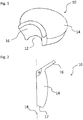
- FIG. 1 shows a sealing element 10 according to a first embodiment of the present invention.
- the sealing element 10 has a Ein buoyllaus Principleung 12, a main body 14 and a filling aid 16.
- the Ein hypochllausströmung 12 is formed as a semicircular recess. It is arranged on a peripheral edge of the main body 14.
- the filling aid 16 is integral with formed the main body 14 and connects directly to the Ein colllausnaturalung 12.
- the filling aid 16 is formed as a channel with a semicircular profile.
- the sealing element 10 may have a foam or be formed as a foam part.
- the sealing element 10 is compressible. As a result, the sealing element 10 can be used in apertures of different sizes.
- FIG. 1 illustrated sealing element 10, in particular the main body 14 is formed substantially as a round disc.
- the main body 14 of the sealing element 10 may also have other geometries that are suitable to seal a wall or ceiling opening.
- the main body is slightly bulged. This can have manufacturing reasons.
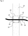
- FIG. 2 shows the sealing element 10 in a side view.
- the filling aid 16 encloses an obtuse angle ⁇ with the main body 14.
- the filling aid 16 extends obliquely upward in a direction when the sealing element 10 is mounted in a wall 22, as in FIG FIG. 3 shown.
- a liquid sealing material 30 can thus run via the filling aid 16 into a cavity 19 behind the sealing element 10.
- the main body 14 of the sealing element 10 extends substantially along a main expansion surface 18, which in FIG. 2 is indicated by a dashed line.
- the filling aid 16 extends in a direction parallel to the main expansion surface 18 beyond a peripheral edge of the main body 14. This leakage of liquid sealant can be prevented when the sealing element 10 is mounted in a wall opening. This is related to FIG. 5 clear.
- an insertion bevel 17 is arranged, which simplifies an assembly of the sealing element 10 in an opening.
- FIG. 3 shows a sealing element 10, which is mounted in an opening 20 of a wall 22.
- another sealing element 24th mounted, which, however, has no filling aid and no Einhellaus Principleung.
- the sealing element 24 can also be replaced by a sealing element 10 with a filling aid. Then the cavity 19 could be filled from both sides.
- the two sealing elements 10, 24 each have an opening 26 through which a line 28 extends.
- liquid sealing material 30 is poured through the Ein colllaus principleung 12 in the formed between the sealing elements 24 and 10 cavity 19.
- the sealing material 30 is not poured directly into the Ein colllaus principleung 12, but for example from a pot first on the gutter-shaped Einhell Anlagen 16. Since the Einglall Anlagen 16 projects obliquely upwards, the sealing material 30 runs by itself through the Ein colllaus Principleung 12 in the cavity 19th
- sealing material 30 is poured into the cavity 19 until the opening 20 is filled with sealing material 30 beyond an upper point. This condition is in FIG. 5 shown. The cavity 19 is thus completely filled with sealing material 30 without air inclusions remaining in the cavity 19.
- the filling aid 16 can be cut off together with a part of the cured sealing material. As a result, an outer surface of the wall 22 remains flat, and the filling aid 16 does not interfere with a subsequent plastering of the wall.
- FIG. 7 shows a sealing element 10 according to another aspect of the invention.
- the sealing element 10 has a main body 14 and a Ein buoyllaus Principleung 12.
- FIG. 8 shows the sealing element 10 according to FIG. 7 in a state mounted in a wall 22.
- the sealing element 10 is on a front side of a Breakthrough 20 mounted.
- another sealing element 24 is mounted. Both the sealing element 10 and the sealing element 24 have openings 26 through which a line 28 extends. Between the sealing elements 10, 24 is a cavity 19th
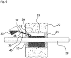
- FIG. 9 shows the filling of the cavity 19 with liquid sealing material 30.
- a filling aid 32 is guided through the Ein Schollaus Principleung 12.
- the filling aid 32 is formed as a groove, but it can also be designed as a tube or funnel.
- the liquid sealing material 30 is poured from a jug or similar vessel onto the filling aid 32 so that the liquid sealing material 30 can flow into the cavity 19 through the filling recess 12.
- the filling aid 32 can be held either by hand or by a holding device 36.
- the holding device 36 has a pipe clamp 38, in which the filling aid 32 is clamped.
- the holding device 36 can have a further fastening means 40, for example a stand or another clamp, in order to hold the holding device 36 in a stable position during the drying process.
- the holding device 36 may be attached to the pipe 28 with another pipe clamp.
- the Ein Schollaus Principleung 12 of the sealing element 10 is closed with a plug 34.
- the plug 34 may be formed of the same material as the sealing element 10. By the plug 34 ensures that the sealing material 30 remains until fully cured in the cavity 19 and does not leak.
- the sealing element 10, the filling aid 32 and the plug 34 together form a fire protection set.
Landscapes
- Engineering & Computer Science (AREA)
- Architecture (AREA)
- Civil Engineering (AREA)
- Structural Engineering (AREA)
- General Engineering & Computer Science (AREA)
- Mechanical Engineering (AREA)
- Building Environments (AREA)
Priority Applications (2)
| Application Number | Priority Date | Filing Date | Title |
|---|---|---|---|
| EP17170388.7A EP3401582A1 (fr) | 2017-05-10 | 2017-05-10 | Élément d'étanchéité et kit de protection incendie comprenant un élément d'étanchéité |
| PCT/EP2018/060849 WO2018206313A1 (fr) | 2017-05-10 | 2018-04-27 | Élément d'étanchéité et ensemble de protection anti-incendie comprenant un élément d'étanchéité |
Applications Claiming Priority (1)
| Application Number | Priority Date | Filing Date | Title |
|---|---|---|---|
| EP17170388.7A EP3401582A1 (fr) | 2017-05-10 | 2017-05-10 | Élément d'étanchéité et kit de protection incendie comprenant un élément d'étanchéité |
Publications (1)
| Publication Number | Publication Date |
|---|---|
| EP3401582A1 true EP3401582A1 (fr) | 2018-11-14 |
Family
ID=58701467
Family Applications (1)
| Application Number | Title | Priority Date | Filing Date |
|---|---|---|---|
| EP17170388.7A Withdrawn EP3401582A1 (fr) | 2017-05-10 | 2017-05-10 | Élément d'étanchéité et kit de protection incendie comprenant un élément d'étanchéité |
Country Status (2)
| Country | Link |
|---|---|
| EP (1) | EP3401582A1 (fr) |
| WO (1) | WO2018206313A1 (fr) |
Families Citing this family (1)
| Publication number | Priority date | Publication date | Assignee | Title |
|---|---|---|---|---|
| CN117587942A (zh) * | 2023-11-03 | 2024-02-23 | 中冶天工集团天津有限公司 | 一种防辐射混凝土墙洞与填充墙体密实封堵方法 |
Citations (5)
| Publication number | Priority date | Publication date | Assignee | Title |
|---|---|---|---|---|
| DE6950007U (de) * | 1969-12-27 | 1970-06-25 | Denso Chemie Gmbh | Futterrohr fuer mauerdurchfuehrungen |
| DE3606339A1 (de) * | 1986-02-27 | 1987-09-03 | Bbc Brown Boveri & Cie | Brand- und strahlensichere wand- und/oder deckendurchfuehrung |
| US20060006611A1 (en) * | 2004-07-07 | 2006-01-12 | Christian Foerg | Device for sealing a leadthrough for conduits in a constructional element |
| DE202011108154U1 (de) * | 2011-11-21 | 2012-01-16 | Markus Swoboda | Mauerdurchführungssystem mit Flanschen |
| EP2493041A2 (fr) * | 2011-02-23 | 2012-08-29 | HILTI Aktiengesellschaft | Exécution d'un élément de guidage |
-
2017
- 2017-05-10 EP EP17170388.7A patent/EP3401582A1/fr not_active Withdrawn
-
2018
- 2018-04-27 WO PCT/EP2018/060849 patent/WO2018206313A1/fr not_active Ceased
Patent Citations (5)
| Publication number | Priority date | Publication date | Assignee | Title |
|---|---|---|---|---|
| DE6950007U (de) * | 1969-12-27 | 1970-06-25 | Denso Chemie Gmbh | Futterrohr fuer mauerdurchfuehrungen |
| DE3606339A1 (de) * | 1986-02-27 | 1987-09-03 | Bbc Brown Boveri & Cie | Brand- und strahlensichere wand- und/oder deckendurchfuehrung |
| US20060006611A1 (en) * | 2004-07-07 | 2006-01-12 | Christian Foerg | Device for sealing a leadthrough for conduits in a constructional element |
| EP2493041A2 (fr) * | 2011-02-23 | 2012-08-29 | HILTI Aktiengesellschaft | Exécution d'un élément de guidage |
| DE202011108154U1 (de) * | 2011-11-21 | 2012-01-16 | Markus Swoboda | Mauerdurchführungssystem mit Flanschen |
Also Published As
| Publication number | Publication date |
|---|---|
| WO2018206313A1 (fr) | 2018-11-15 |
Similar Documents
| Publication | Publication Date | Title |
|---|---|---|
| EP2806199B1 (fr) | Passage de câble | |
| DE102004030810B4 (de) | Verbinder und Verfahren zu seiner Herstellung | |
| DE102004032869A1 (de) | Vorrichtung zum Abdichten einer Durchführung für Leitungen in einem Bauteil | |
| CH631507A5 (de) | Verbauvorrichtung fuer leitungsgraeben. | |
| DE2203370A1 (de) | Vorrichtung zum verankern von rohrleitungsaustritten in der wand | |
| EP2689808A2 (fr) | Module pour un passage de ligne | |
| DE102005046149B4 (de) | Vorrichtung zum Abführen von Oberflächenwasser und zum Brandschutz | |
| DE9410742U1 (de) | Einbaukasten | |
| AT15972U1 (de) | Installationsblock | |
| WO2018206313A1 (fr) | Élément d'étanchéité et ensemble de protection anti-incendie comprenant un élément d'étanchéité | |
| DE2106482C3 (de) | Auslaß an einem Kanal für Unterflur- und Unterputzinstallation | |
| DE102010004356A1 (de) | Schaumstoff-Duschbodenelement | |
| DE102018005720B4 (de) | Verwendung einer Durchführung zum Eingießen in eine Bodenplatte | |
| EP2857611B1 (fr) | Soupirail et procédé de montage d'un soupirail | |
| DE102014102260B4 (de) | Baukasten für die Abdichtung des Durchganges von Kabeln oder Adern, die durch eine Platte verlaufen sowie Verfahren zum Abdichten | |
| DE2726672C3 (de) | Wanddurchführung für Erdleiter, insbesondere Erdbandeisen | |
| EP2363552B1 (fr) | Utilisation d'une réhausse pour le réhaussement sur un bourrage d'étanchéité | |
| EP1785540B1 (fr) | Dispositif pour le drainage des eaux de surface avec protection de feu | |
| DE10323589A1 (de) | Brand- und Schallschutzvorrichtungen für Rohrleitungssysteme sowie Brand- und Schallschutzprofile und -hülsen | |
| DE202021100119U1 (de) | Dichtungsvorrichtung mit einer Vergussmanschette und Installationsanordnung | |
| EP3312958B1 (fr) | Boîtier d'installation pour l'installation électrique | |
| EP3470718A1 (fr) | Dispositif de protection contre l'incendie | |
| DE9410808U1 (de) | Haltevorrichtung zur Montage von Kabeln und ähnlichen Leitungen in einem Kanal | |
| EP1363058B1 (fr) | Dispositif d'étancheité pour ouvertures dans les murs | |
| DE2450571C3 (de) | Transformatorstation |
Legal Events
| Date | Code | Title | Description |
|---|---|---|---|
| PUAI | Public reference made under article 153(3) epc to a published international application that has entered the european phase |
Free format text: ORIGINAL CODE: 0009012 |
|
| AK | Designated contracting states |
Kind code of ref document: A1 Designated state(s): AL AT BE BG CH CY CZ DE DK EE ES FI FR GB GR HR HU IE IS IT LI LT LU LV MC MK MT NL NO PL PT RO RS SE SI SK SM TR |
|
| AX | Request for extension of the european patent |
Extension state: BA ME |
|
| STAA | Information on the status of an ep patent application or granted ep patent |
Free format text: STATUS: THE APPLICATION IS DEEMED TO BE WITHDRAWN |
|
| 18D | Application deemed to be withdrawn |
Effective date: 20190515 |