EP3402941B1 - Élément support pour des surfaces surélevées - Google Patents
Élément support pour des surfaces surélevées Download PDFInfo
- Publication number
- EP3402941B1 EP3402941B1 EP17702015.3A EP17702015A EP3402941B1 EP 3402941 B1 EP3402941 B1 EP 3402941B1 EP 17702015 A EP17702015 A EP 17702015A EP 3402941 B1 EP3402941 B1 EP 3402941B1
- Authority
- EP
- European Patent Office
- Prior art keywords
- support element
- connecting pieces
- shock
- relief
- connecting piece
- Prior art date
- Legal status (The legal status is an assumption and is not a legal conclusion. Google has not performed a legal analysis and makes no representation as to the accuracy of the status listed.)
- Active
Links
Images


Classifications
-
- E—FIXED CONSTRUCTIONS
- E04—BUILDING
- E04F—FINISHING WORK ON BUILDINGS, e.g. STAIRS, FLOORS
- E04F15/00—Flooring
- E04F15/02—Flooring or floor layers composed of a number of similar elements
- E04F15/024—Sectional false floors, e.g. computer floors
- E04F15/02447—Supporting structures
-
- E—FIXED CONSTRUCTIONS
- E04—BUILDING
- E04F—FINISHING WORK ON BUILDINGS, e.g. STAIRS, FLOORS
- E04F15/00—Flooring
- E04F15/02—Flooring or floor layers composed of a number of similar elements
- E04F15/024—Sectional false floors, e.g. computer floors
- E04F15/02447—Supporting structures
- E04F15/02464—Height adjustable elements for supporting the panels or a panel-supporting framework
Definitions
- the present invention relates to a support element for holding an object at a distance from an underlying surface, and in particular, for the support of raised surfaces.
- Support elements for raised surfaces are commonly used for all types of applications such as raised roofs, terraces, or technical flooring for outdoor and indoor applications.
- An example can be found in GB2378457 , in which a support element for floors, ceilings, and walls is disclosed.
- DE2457743A1 shows an element showing the features of the preamble of claim 1. A common requirement when mounting such a raised surface is that a sufficiently level surface is obtained and a sufficiently stable surface.
- shocks or vibrations to which the raised surface is exposed can to a greater or lesser degree be absorbed so that (i) the load on the raised surface as a result of these shocks and vibrations can be reduced, and/or (ii) these shocks and vibrations can be transmitted maximally unamplified, and preferably weakened, to the underlying surface.
- the present invention relates to a support element for holding an object at a distance from an underlying surface according to the appended claim 1.
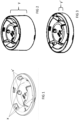
- FIG. 1 to 8 illustrate different embodiments of a support element according to the present invention.
- the support elements according to the present invention are generally suited for holding an object at a distance from an underlying surface.
- these support elements are suitable for holding tiles, beams, battens, etc. for installing raised surfaces, such as an elevated roof terrace, elevated apartment terrace, elevated garden terrace, a stage, a raised technical floor for indoor or outdoor, a raised floor for indoor or outdoor, and the like.
- the underlying surface means the ground, the roof, the platform, the conventional building floor between floors, or any other structure at a distance from which an object, and in particular, tiles, beams, battens, etc. for the installation of raised surfaces must be installed.
- the advantage of the present invention is that the shock and/or vibration absorbing connecting piece provides the support element with increased shock and/or vibration absorption, such that shocks or vibrations can to a greater or lesser degree be absorbed so that (i) the load on the raised surface as a result of these shocks and vibrations can be reduced, and/or (ii) these shocks and vibrations can be transmitted maximally unamplified, and preferably weakened, to the underlying surface. Furthermore, by integrating the shock and/or vibration absorbing properties in a connection piece as part of the support element, instead of as a separate element between the base and underlying surface, the durability of the shock and/or vibration absorbing element is increased.
- a shock and/or vibration absorbing support element takes less work and time than a conventional support element with unintegrated shock and/or vibration absorbing element to be installed separately.
- shock and/or vibration absorbing connecting piece can also contribute to improved sound absorption due to vibration of the raised surface or of the underlying surface.
- the base, the connecting pieces, and the support plate can be made of metal or of any synthetic material that is suitable for extrusion or injection moulding, such as polypropylene, polyethylene (low and high density), polyvinyl chloride, polystyrene, ethyl vinyl acetate, acrylonitrile-butadiene-styrene or polyolefin, or a combination thereof.
- the shock and/or vibration absorbing material in the shock and/or vibration absorbing connecting piece can be any material that can to a greater or lesser degree absorb shocks and/or vibrations, such as, for example, rubber, foam, fibres, air cushions, chambers or cells with enclosed liquid or gas.
- the shock and/or vibration absorbing connecting piece can consist of a frame that comprises a shock and/or vibration absorbing material (for example, a more or less supple casing filled with fibres or gas, cf. a tennis ball), or a frame that is at least partly enveloped by the shock and/or vibration absorbing material (for example, a metal or synthetic skeleton enveloped by rubber or foam).
- the shock and/or vibration absorbing connecting piece can preferably also consist completely of shock and/or vibration absorbing material. It can be made of any shock and/or vibration absorbing synthetic material which is suitable for extrusion or injection moulding, such as polystyrene, polyurethane, polyester, polyethylene, etc., or it may be made of rubber, synthetic or natural, and preferably recycled rubber, or a combination of rubber and a synthetic material. In the case of rubber, the shock and/or vibration absorbing connecting piece can be made by compression moulding of rubber (whether recycled or granulated) and a polymer, for example, polyurethane.
- the shock and/or vibration absorbing connecting piece should preferably have a compression of just a few millimetres, less than 5 mm, or even less than 3 mm, at a load which is common for all kinds of applications such as elevated roofs, terraces, or technical flooring for outdoor and indoor applications, and this depending on the chosen shock and/or vibration absorbing material.
- the shock and/or vibration absorbing material can be chosen according to the maximum desired or permitted compression set (which is a measure of the permanent deformation when a compressive force is removed) according to standard ASTM D395, the foregoing according to the shock and/or vibration absorbing capacity of the connecting piece.
- the shock and/or vibration absorbing connecting piece can be provided with means allowing it to be attached to the underlying and/or overlying connecting pieces, or in the absence of multiple connecting pieces, to the base and/or the support plate, for example, click systems or snap-fit clips.
- the shock and/or vibration absorbing connecting piece can also be attached by means of gluing or welding.
- the shock and/or vibration absorbing connecting piece can have a geometry that engages the underlying and/or overlying connecting pieces, if any, or in the absence of multiple connecting pieces, the base and/or the support plate.
- the aforementioned geometry can, for example, be a raised edge at the periphery, such that the shock and/or vibration absorbing connecting piece cannot slide or be pressed out of the support element.
- the geometry can also exhibit a relief on at least one side parallel with the underlying surface, having one or more projections and/or one or more cavities, which fit into a complementary relief of an overlying or underlying connecting piece, or in the absence of multiple connecting pieces, into a complementary relief on the base and/or the support plate.
- FIG. 1 illustrates such a shock and/or vibration absorbing connecting piece with a pronounced relief that engages and/or is complementary with other parts of the support element, the foregoing in combination with snap-fit clips (x and x').
- FIG. 2 and 3 illustrate two shock and/or vibration absorbing connecting pieces as described in the previous section, with different height, such that the height of the support element can be changed according to the desired application, by choosing a different height of shock and/or vibration absorbing connecting piece.
- the one or more stackable connecting pieces including the shock and/or vibration absorbing connecting piece, exhibit a relief parallel to the underlying surface on both sides, having one or more projections and/or one or more cavities allowing several connecting pieces to be stacked such that the projecting portions of one connecting piece fit into the cavities of an overlying or underlying connecting piece.
- An advantage of the invention is that the use of connecting pieces with a relief that allow different connecting pieces to fit on each other provides increased stability because the connecting pieces cannot slide out of each other due to the relief, which is particularly important for the shock and/or vibration absorbing connecting piece since this will tend to be pushed out of the support element by compression.
- a second advantage is that such relief is a passive and therefore durable system to link connecting pieces to each other.
- a third advantage is that the connecting pieces provide increased height adjustability such that applications where relatively large irregularities in the underlying surface need to be accommodated and/or where the distance between the raised surface and the underlying surface is relatively large are among the possibilities.
- the relief of one or more projections and/or one or more cavities can comprise any combination of projections and/or cavities.
- the relief on both sides of the connecting piece parallel with the underlying surface can be identical or can be different.
- the support element is characterised by connecting pieces, including the shock and/or vibration absorbing connecting piece, with a relief on one side, parallel with the underlying surface, which is complementary to the relief on the opposite side.
- a 'complementary relief' means that the relief on one side parallel to the underlying surface would theoretically fit on the relief on the opposite side parallel to the underlying surface. In this way, any connecting piece will fit on any other connecting piece, and connecting pieces can be exchanged with connecting pieces with a different height.
- the support element can therefore be built up with exchangeable connecting pieces of different heights depending on the desired distance between the underlying surface and the object which is to be supported.
- the one or more projections and/or one or more cavities can have any form.
- the one or more projections (5) in the relief taper towards their free end, and the cavities (6) are defined by side walls and a base, the side walls of a cavity tapering towards the base.
- the protrusions are therefore mastaba-shaped or even pyramid-shaped, while the cavities are in the form of an inverted mastaba or even an inverted pyramid.
- each of the connecting pieces including the shock and/or vibration absorbing connecting piece, include one projection that is carried out annularly in the vicinity of the outer circumference of one side parallel with the underlying surface, and includes one cavity that is carried out annularly in the vicinity of the outer circumference of the opposite side parallel with the underlying surface.
- the projection is disc-shaped, and the cavity is also disc-shaped.
- the connecting pieces can be provided with means allowing the connecting pieces to be interconnected, for example, by means of click systems or snap-fit clips.
- Each connecting piece can have a height, measured in the vertical direction of the upright support element, between 5 and 150 mm, preferably 15 mm, 50 mm and 100 mm.
- the base (1) of the support element includes a disc-shaped cavity in which a ring-shaped element (7) with internal screw thread fits engaging with a control piece (8) with corresponding external screw thread, the control piece exhibiting a relief on the highest side parallel with the underlying surface of one or more projections and/or one or more cavities complementary to the relief of a connecting piece of the one or more connecting pieces (see circle).
- the ring-shaped element consequently enters the disc-shaped cavity of the base.
- the control piece is fastened by screwing it into the internal screw thread of the ring-shaped element.
- a support element according to the present invention provides stepless height control which, in combination with the stackable connecting pieces (3), can bridge a very large difference in height.
- the screw thread of the control piece has such a length, measured in the vertical direction of the upright support element, that it can bridge a difference in height which is at least equal to the height of the connecting piece with the lowest height among the connecting pieces.
- the connecting piece with the lowest height has a height of 50 mm
- the screw thread of the control piece must be able to bridge at least 50 mm, so that the support element obtains a stepless height control from 0 to 150 mm depending on whether no, one or two connecting pieces of 50 mm are used.
- FIG. 8 shows a support element according to the present invention that can hold an object at a distance of between 70 and 327 mm from an underlying surface, the foregoing being infinitely variable if use is made of a circular element (7) and a control piece (8) with screw thread of 57 mm in height and provided the connecting pieces of 50 mm (3') and 100 mm (3") in height are used correctly.
- the underside of the support plate has a relief complementary to the relief of the one or more connecting pieces such that the support plate can also be placed on the intermediate piece in a stable and durable manner.
- the highest side of the control piece parallel to the underlying surface and viewed according to the vertical direction of the upright support element can possess a relief complementary to the relief of the one or more connecting pieces such that the one or more connecting pieces can be placed on the control piece in a stable and durable manner.
- control piece can be provided with means which make it possible to fix the lower connecting piece to the control piece, for example, by means of click systems or snap-fit clips.
- the ring-shaped element and the control piece may be made of any synthetic material that is suitable for extrusion or injection moulding, or of metal.
Landscapes
- Engineering & Computer Science (AREA)
- Architecture (AREA)
- General Engineering & Computer Science (AREA)
- Civil Engineering (AREA)
- Structural Engineering (AREA)
- Vibration Prevention Devices (AREA)
Claims (8)
- Élément de support pour une surface surélevée, comprenant les parties suivantes :(a) une base permettant à l'élément de support d'être placé en position verticale sur une surface sous-jacente,(b) sur la base, une pièce intermédiaire constituée d'une ou plusieurs pièces de liaison empilables présentant un relief sur au moins un côté parallèle à la surface sous-jacente, comportant une ou plusieurs saillies et/ou une ou plusieurs cavités, qui s'insèrent dans un relief complémentaire d'une pièce de liaison sus-jacente ou sous-jacente, ou en l'absence de pièces de liaison multiples, dans un relief complémentaire de la base et/ou de la plaque de support, et(c) sur la pièce intermédiaire, une plaque de support, convenant comme support d'un objet à une certaine distance de la surface sous-jacente, caractérisée par le fait que la ou les pièces de liaison empilables comprennent une pièce de liaison absorbant les chocs et/ou les vibrations, constituée au moins en partie d'un matériau absorbant les chocs et/ou les vibrations, dans laquelle la ou les pièces de liaison empilables, y compris la pièce de liaison absorbant les chocs et/ou les vibrations, présentent un relief parallèle à la surface sous-jacente sur les deux côtés, comportant une ou plusieurs saillies et/ou une ou plusieurs cavités. Celles-ci permettent d'empiler plusieurs pièces de liaison de telle sorte que les parties saillantes d'une pièce de liaison s'insèrent dans les cavités d'une pièce de liaison sus-jacente ou sous-jacente, caractérisée par le fait que chacune de ces pièces de liaison, y compris la pièce de liaison absorbant les chocs et/ou les vibrations, comporte une saillie de forme annulaire à proximité de la circonférence extérieure d'un côté parallèle à la surface sous-jacente, et comporte une cavité de forme annulaire à proximité de la circonférence extérieure du côté opposé parallèle à la surface sous-jacente.
- Élément de support selon la revendication 1, caractérisé par le fait que la pièce de liaison absorbant les chocs et/ou les vibrations est entièrement constituée d'un matériau absorbant les chocs et/ou les vibrations.
- Élément de support selon les revendications 1 ou 2, caractérisé par le fait que la pièce de liaison absorbant les chocs et/ou les vibrations est pourvue de moyens lui permettant d'être fixée aux pièces de liaison sous-jacentes et/ou sus-jacentes, le cas échéant, ou, en l'absence de pièces de liaison multiples, à la base et/ou à la plaque de support.
- Élément de support selon la revendication 1, caractérisé par le fait que le relief d'un côté est complémentaire au relief du côté opposé.
- Élément de support selon l'une quelconque des revendications précédentes, caractérisé par le fait qu'une ou plusieurs desdites pièces de liaison sont pourvues de moyens permettant d'interconnecter les pièces de liaison.
- Élément de support selon l'une quelconque des revendications précédentes, caractérisé par le fait que chaque pièce de liaison a une hauteur, mesurée dans le sens vertical de l'élément de support, comprise entre 5 et 150 mm.
- Élément de support selon l'une quelconque des revendications précédentes, caractérisé par le fait que la base comprend une cavité en forme de disque dans laquelle un élément en forme d'anneau avec filetage intérieur s'adapte par emboîtement dans une pièce de commande avec filetage extérieur correspondant, la pièce de commande présentant un relief sur le côté le plus élevé parallèle à la surface sous-jacente d'une ou plusieurs saillies et/ou d'une ou plusieurs cavités complémentaires au relief d'une pièce de liaison de la ou des pièces de liaison.
- Élément de support selon l'une quelconque des revendications précédentes, caractérisé par le fait que le filetage de la pièce de commande peut combler une différence de hauteur au moins égale à la hauteur de la pièce de liaison dont la hauteur est la plus faible parmi les pièces de liaison.
Applications Claiming Priority (2)
| Application Number | Priority Date | Filing Date | Title |
|---|---|---|---|
| BE2016/0007A BE1023786B1 (nl) | 2016-01-14 | 2016-01-14 | Dragerelement voor verhoogde oppervlakken |
| PCT/EP2017/050817 WO2017121899A1 (fr) | 2016-01-14 | 2017-01-16 | Élément support pour des surfaces surélevées |
Publications (2)
| Publication Number | Publication Date |
|---|---|
| EP3402941A1 EP3402941A1 (fr) | 2018-11-21 |
| EP3402941B1 true EP3402941B1 (fr) | 2023-08-16 |
Family
ID=55456496
Family Applications (1)
| Application Number | Title | Priority Date | Filing Date |
|---|---|---|---|
| EP17702015.3A Active EP3402941B1 (fr) | 2016-01-14 | 2017-01-16 | Élément support pour des surfaces surélevées |
Country Status (3)
| Country | Link |
|---|---|
| EP (1) | EP3402941B1 (fr) |
| BE (1) | BE1023786B1 (fr) |
| WO (1) | WO2017121899A1 (fr) |
Families Citing this family (1)
| Publication number | Priority date | Publication date | Assignee | Title |
|---|---|---|---|---|
| CN110512829B (zh) * | 2019-08-28 | 2021-04-13 | 浙江万瑞建设有限公司 | 一种房建地板结构 |
Citations (4)
| Publication number | Priority date | Publication date | Assignee | Title |
|---|---|---|---|---|
| DE2457743A1 (de) * | 1974-12-06 | 1976-06-16 | Goldbach Gmbh Holz Kunststoffu | Hoehenverstellbares stuetzelement |
| FR2639666A1 (fr) * | 1988-09-27 | 1990-06-01 | Jou Plast Sa | Plot reglable pour le support d'elements de sol, tels que dalles, caillebotis, ou analogues |
| US4953658A (en) * | 1989-06-07 | 1990-09-04 | Ohbayashi Corporation | Seismic isolator |
| EP0767318A2 (fr) * | 1995-10-06 | 1997-04-09 | INTEC AACHEN INNOVATIVE TECHNOLOGIEN FÜR DIE BAUSANIERUNG, Dr. Honsinger & Dr. Breitbach | Amortisseur en matériau d'élasticité permanente en forme de natte ou de bande |
Family Cites Families (2)
| Publication number | Priority date | Publication date | Assignee | Title |
|---|---|---|---|---|
| DE4419589A1 (de) * | 1994-06-03 | 1994-10-13 | Ulrich Dipl Ing Hammerschmidt | Abstandshalter zur positionierten Befestigung einer Latte an einer Decke oder Wand |
| GB0418912D0 (en) * | 2004-08-25 | 2004-09-29 | Danskin Flooring Systems Ltd | Improved building components |
-
2016
- 2016-01-14 BE BE2016/0007A patent/BE1023786B1/nl not_active IP Right Cessation
-
2017
- 2017-01-16 EP EP17702015.3A patent/EP3402941B1/fr active Active
- 2017-01-16 WO PCT/EP2017/050817 patent/WO2017121899A1/fr not_active Ceased
Patent Citations (4)
| Publication number | Priority date | Publication date | Assignee | Title |
|---|---|---|---|---|
| DE2457743A1 (de) * | 1974-12-06 | 1976-06-16 | Goldbach Gmbh Holz Kunststoffu | Hoehenverstellbares stuetzelement |
| FR2639666A1 (fr) * | 1988-09-27 | 1990-06-01 | Jou Plast Sa | Plot reglable pour le support d'elements de sol, tels que dalles, caillebotis, ou analogues |
| US4953658A (en) * | 1989-06-07 | 1990-09-04 | Ohbayashi Corporation | Seismic isolator |
| EP0767318A2 (fr) * | 1995-10-06 | 1997-04-09 | INTEC AACHEN INNOVATIVE TECHNOLOGIEN FÜR DIE BAUSANIERUNG, Dr. Honsinger & Dr. Breitbach | Amortisseur en matériau d'élasticité permanente en forme de natte ou de bande |
Also Published As
| Publication number | Publication date |
|---|---|
| WO2017121899A1 (fr) | 2017-07-20 |
| EP3402941A1 (fr) | 2018-11-21 |
| BE1023786A1 (nl) | 2017-07-26 |
| BE1023786B1 (nl) | 2017-07-27 |
Similar Documents
| Publication | Publication Date | Title |
|---|---|---|
| CA2118800C (fr) | Membrane protectrice amelioree, particulierement pour les planchers | |
| US9499992B2 (en) | Precision height adjustable flooring substrate support sytem | |
| KR101319511B1 (ko) | 엘리베이티드 플로어의 패널 부재들을 지지하기 위한 조정 가능한 받침대 및 그 받침대용 경사 조정 가능 헤드 | |
| CA2845223C (fr) | Piedestal de plate-forme de blocs de lest | |
| CA2838374C (fr) | Systeme de maintien pour tuiles de surface surelevee | |
| US8505256B2 (en) | Synthetic floor tile having partially-compliant support structure | |
| US20120272589A1 (en) | Structural systems for restraining elevated surface tiles | |
| KR101302936B1 (ko) | 단지, 조경, 공원, 하천, 도로에 사용되는 데크 조립체 | |
| CA3041229A1 (fr) | Support de planchers sureleves | |
| US20130008741A1 (en) | Sound-insulating and vibration-isolating rubber pad and method for installing a sound-insulating and vibration-isolating floor using same | |
| WO2015030255A1 (fr) | Plancher à accès dégagé | |
| EP3402941B1 (fr) | Élément support pour des surfaces surélevées | |
| US11002023B2 (en) | Flooring support system | |
| EP3347547B1 (fr) | Élément de support pour des surfaces élevées | |
| US10829941B2 (en) | Flooring support system | |
| JP7381857B2 (ja) | 段差修正装置 | |
| US10815673B2 (en) | Flooring support system | |
| KR101428760B1 (ko) | 층간소음 바닥재 | |
| JP3159295U (ja) | 防振材、該防振材を用いた防振床構造 | |
| US10794067B2 (en) | Flooring support system | |
| US10815678B2 (en) | Flooring support system | |
| KR20180062670A (ko) | 충격 및 소음 감쇄장치, 그 제조방법, 및 그것을 이용한 공동주택 뜬바닥 구조 | |
| US20200190816A1 (en) | Flooring Support System | |
| KR20210011613A (ko) | 마루틀 고정장치 | |
| KR102547743B1 (ko) | 데크 및 플로어 설치 공법 |
Legal Events
| Date | Code | Title | Description |
|---|---|---|---|
| STAA | Information on the status of an ep patent application or granted ep patent |
Free format text: STATUS: UNKNOWN |
|
| STAA | Information on the status of an ep patent application or granted ep patent |
Free format text: STATUS: THE INTERNATIONAL PUBLICATION HAS BEEN MADE |
|
| PUAI | Public reference made under article 153(3) epc to a published international application that has entered the european phase |
Free format text: ORIGINAL CODE: 0009012 |
|
| STAA | Information on the status of an ep patent application or granted ep patent |
Free format text: STATUS: REQUEST FOR EXAMINATION WAS MADE |
|
| 17P | Request for examination filed |
Effective date: 20180814 |
|
| AK | Designated contracting states |
Kind code of ref document: A1 Designated state(s): AL AT BE BG CH CY CZ DE DK EE ES FI FR GB GR HR HU IE IS IT LI LT LU LV MC MK MT NL NO PL PT RO RS SE SI SK SM TR |
|
| AX | Request for extension of the european patent |
Extension state: BA ME |
|
| DAV | Request for validation of the european patent (deleted) | ||
| DAX | Request for extension of the european patent (deleted) | ||
| STAA | Information on the status of an ep patent application or granted ep patent |
Free format text: STATUS: EXAMINATION IS IN PROGRESS |
|
| 17Q | First examination report despatched |
Effective date: 20201218 |
|
| GRAP | Despatch of communication of intention to grant a patent |
Free format text: ORIGINAL CODE: EPIDOSNIGR1 |
|
| STAA | Information on the status of an ep patent application or granted ep patent |
Free format text: STATUS: GRANT OF PATENT IS INTENDED |
|
| GRAS | Grant fee paid |
Free format text: ORIGINAL CODE: EPIDOSNIGR3 |
|
| INTG | Intention to grant announced |
Effective date: 20230613 |
|
| GRAA | (expected) grant |
Free format text: ORIGINAL CODE: 0009210 |
|
| STAA | Information on the status of an ep patent application or granted ep patent |
Free format text: STATUS: THE PATENT HAS BEEN GRANTED |
|
| AK | Designated contracting states |
Kind code of ref document: B1 Designated state(s): AL AT BE BG CH CY CZ DE DK EE ES FI FR GB GR HR HU IE IS IT LI LT LU LV MC MK MT NL NO PL PT RO RS SE SI SK SM TR |
|
| REG | Reference to a national code |
Ref country code: GB Ref legal event code: FG4D |
|
| REG | Reference to a national code |
Ref country code: CH Ref legal event code: EP |
|
| REG | Reference to a national code |
Ref country code: DE Ref legal event code: R096 Ref document number: 602017072741 Country of ref document: DE |
|
| REG | Reference to a national code |
Ref country code: IE Ref legal event code: FG4D |
|
| REG | Reference to a national code |
Ref country code: LT Ref legal event code: MG9D |
|
| REG | Reference to a national code |
Ref country code: NL Ref legal event code: MP Effective date: 20230816 |
|
| REG | Reference to a national code |
Ref country code: AT Ref legal event code: MK05 Ref document number: 1600211 Country of ref document: AT Kind code of ref document: T Effective date: 20230816 |
|
| PG25 | Lapsed in a contracting state [announced via postgrant information from national office to epo] |
Ref country code: GR Free format text: LAPSE BECAUSE OF FAILURE TO SUBMIT A TRANSLATION OF THE DESCRIPTION OR TO PAY THE FEE WITHIN THE PRESCRIBED TIME-LIMIT Effective date: 20231117 |
|
| PG25 | Lapsed in a contracting state [announced via postgrant information from national office to epo] |
Ref country code: IS Free format text: LAPSE BECAUSE OF FAILURE TO SUBMIT A TRANSLATION OF THE DESCRIPTION OR TO PAY THE FEE WITHIN THE PRESCRIBED TIME-LIMIT Effective date: 20231216 |
|
| PG25 | Lapsed in a contracting state [announced via postgrant information from national office to epo] |
Ref country code: SE Free format text: LAPSE BECAUSE OF FAILURE TO SUBMIT A TRANSLATION OF THE DESCRIPTION OR TO PAY THE FEE WITHIN THE PRESCRIBED TIME-LIMIT Effective date: 20230816 Ref country code: RS Free format text: LAPSE BECAUSE OF FAILURE TO SUBMIT A TRANSLATION OF THE DESCRIPTION OR TO PAY THE FEE WITHIN THE PRESCRIBED TIME-LIMIT Effective date: 20230816 Ref country code: PT Free format text: LAPSE BECAUSE OF FAILURE TO SUBMIT A TRANSLATION OF THE DESCRIPTION OR TO PAY THE FEE WITHIN THE PRESCRIBED TIME-LIMIT Effective date: 20231218 Ref country code: NO Free format text: LAPSE BECAUSE OF FAILURE TO SUBMIT A TRANSLATION OF THE DESCRIPTION OR TO PAY THE FEE WITHIN THE PRESCRIBED TIME-LIMIT Effective date: 20231116 Ref country code: NL Free format text: LAPSE BECAUSE OF FAILURE TO SUBMIT A TRANSLATION OF THE DESCRIPTION OR TO PAY THE FEE WITHIN THE PRESCRIBED TIME-LIMIT Effective date: 20230816 Ref country code: LV Free format text: LAPSE BECAUSE OF FAILURE TO SUBMIT A TRANSLATION OF THE DESCRIPTION OR TO PAY THE FEE WITHIN THE PRESCRIBED TIME-LIMIT Effective date: 20230816 Ref country code: LT Free format text: LAPSE BECAUSE OF FAILURE TO SUBMIT A TRANSLATION OF THE DESCRIPTION OR TO PAY THE FEE WITHIN THE PRESCRIBED TIME-LIMIT Effective date: 20230816 Ref country code: IS Free format text: LAPSE BECAUSE OF FAILURE TO SUBMIT A TRANSLATION OF THE DESCRIPTION OR TO PAY THE FEE WITHIN THE PRESCRIBED TIME-LIMIT Effective date: 20231216 Ref country code: HR Free format text: LAPSE BECAUSE OF FAILURE TO SUBMIT A TRANSLATION OF THE DESCRIPTION OR TO PAY THE FEE WITHIN THE PRESCRIBED TIME-LIMIT Effective date: 20230816 Ref country code: GR Free format text: LAPSE BECAUSE OF FAILURE TO SUBMIT A TRANSLATION OF THE DESCRIPTION OR TO PAY THE FEE WITHIN THE PRESCRIBED TIME-LIMIT Effective date: 20231117 Ref country code: FI Free format text: LAPSE BECAUSE OF FAILURE TO SUBMIT A TRANSLATION OF THE DESCRIPTION OR TO PAY THE FEE WITHIN THE PRESCRIBED TIME-LIMIT Effective date: 20230816 Ref country code: AT Free format text: LAPSE BECAUSE OF FAILURE TO SUBMIT A TRANSLATION OF THE DESCRIPTION OR TO PAY THE FEE WITHIN THE PRESCRIBED TIME-LIMIT Effective date: 20230816 |
|
| PG25 | Lapsed in a contracting state [announced via postgrant information from national office to epo] |
Ref country code: PL Free format text: LAPSE BECAUSE OF FAILURE TO SUBMIT A TRANSLATION OF THE DESCRIPTION OR TO PAY THE FEE WITHIN THE PRESCRIBED TIME-LIMIT Effective date: 20230816 |
|
| PG25 | Lapsed in a contracting state [announced via postgrant information from national office to epo] |
Ref country code: ES Free format text: LAPSE BECAUSE OF FAILURE TO SUBMIT A TRANSLATION OF THE DESCRIPTION OR TO PAY THE FEE WITHIN THE PRESCRIBED TIME-LIMIT Effective date: 20230816 |
|
| PG25 | Lapsed in a contracting state [announced via postgrant information from national office to epo] |
Ref country code: SM Free format text: LAPSE BECAUSE OF FAILURE TO SUBMIT A TRANSLATION OF THE DESCRIPTION OR TO PAY THE FEE WITHIN THE PRESCRIBED TIME-LIMIT Effective date: 20230816 Ref country code: RO Free format text: LAPSE BECAUSE OF FAILURE TO SUBMIT A TRANSLATION OF THE DESCRIPTION OR TO PAY THE FEE WITHIN THE PRESCRIBED TIME-LIMIT Effective date: 20230816 Ref country code: ES Free format text: LAPSE BECAUSE OF FAILURE TO SUBMIT A TRANSLATION OF THE DESCRIPTION OR TO PAY THE FEE WITHIN THE PRESCRIBED TIME-LIMIT Effective date: 20230816 Ref country code: EE Free format text: LAPSE BECAUSE OF FAILURE TO SUBMIT A TRANSLATION OF THE DESCRIPTION OR TO PAY THE FEE WITHIN THE PRESCRIBED TIME-LIMIT Effective date: 20230816 Ref country code: DK Free format text: LAPSE BECAUSE OF FAILURE TO SUBMIT A TRANSLATION OF THE DESCRIPTION OR TO PAY THE FEE WITHIN THE PRESCRIBED TIME-LIMIT Effective date: 20230816 Ref country code: CZ Free format text: LAPSE BECAUSE OF FAILURE TO SUBMIT A TRANSLATION OF THE DESCRIPTION OR TO PAY THE FEE WITHIN THE PRESCRIBED TIME-LIMIT Effective date: 20230816 Ref country code: SK Free format text: LAPSE BECAUSE OF FAILURE TO SUBMIT A TRANSLATION OF THE DESCRIPTION OR TO PAY THE FEE WITHIN THE PRESCRIBED TIME-LIMIT Effective date: 20230816 |
|
| REG | Reference to a national code |
Ref country code: DE Ref legal event code: R097 Ref document number: 602017072741 Country of ref document: DE |
|
| PLBE | No opposition filed within time limit |
Free format text: ORIGINAL CODE: 0009261 |
|
| STAA | Information on the status of an ep patent application or granted ep patent |
Free format text: STATUS: NO OPPOSITION FILED WITHIN TIME LIMIT |
|
| 26N | No opposition filed |
Effective date: 20240517 |
|
| PG25 | Lapsed in a contracting state [announced via postgrant information from national office to epo] |
Ref country code: IT Free format text: LAPSE BECAUSE OF FAILURE TO SUBMIT A TRANSLATION OF THE DESCRIPTION OR TO PAY THE FEE WITHIN THE PRESCRIBED TIME-LIMIT Effective date: 20230816 Ref country code: SI Free format text: LAPSE BECAUSE OF FAILURE TO SUBMIT A TRANSLATION OF THE DESCRIPTION OR TO PAY THE FEE WITHIN THE PRESCRIBED TIME-LIMIT Effective date: 20230816 |
|
| REG | Reference to a national code |
Ref country code: DE Ref legal event code: R119 Ref document number: 602017072741 Country of ref document: DE |
|
| PG25 | Lapsed in a contracting state [announced via postgrant information from national office to epo] |
Ref country code: MC Free format text: LAPSE BECAUSE OF FAILURE TO SUBMIT A TRANSLATION OF THE DESCRIPTION OR TO PAY THE FEE WITHIN THE PRESCRIBED TIME-LIMIT Effective date: 20230816 |
|
| PG25 | Lapsed in a contracting state [announced via postgrant information from national office to epo] |
Ref country code: MC Free format text: LAPSE BECAUSE OF FAILURE TO SUBMIT A TRANSLATION OF THE DESCRIPTION OR TO PAY THE FEE WITHIN THE PRESCRIBED TIME-LIMIT Effective date: 20230816 |
|
| REG | Reference to a national code |
Ref country code: CH Ref legal event code: PL |
|
| PG25 | Lapsed in a contracting state [announced via postgrant information from national office to epo] |
Ref country code: LU Free format text: LAPSE BECAUSE OF NON-PAYMENT OF DUE FEES Effective date: 20240116 |
|
| GBPC | Gb: european patent ceased through non-payment of renewal fee |
Effective date: 20240116 |
|
| PG25 | Lapsed in a contracting state [announced via postgrant information from national office to epo] |
Ref country code: LU Free format text: LAPSE BECAUSE OF NON-PAYMENT OF DUE FEES Effective date: 20240116 |
|
| PG25 | Lapsed in a contracting state [announced via postgrant information from national office to epo] |
Ref country code: DE Free format text: LAPSE BECAUSE OF NON-PAYMENT OF DUE FEES Effective date: 20240801 |
|
| PG25 | Lapsed in a contracting state [announced via postgrant information from national office to epo] |
Ref country code: GB Free format text: LAPSE BECAUSE OF NON-PAYMENT OF DUE FEES Effective date: 20240116 |
|
| PG25 | Lapsed in a contracting state [announced via postgrant information from national office to epo] |
Ref country code: BE Free format text: LAPSE BECAUSE OF NON-PAYMENT OF DUE FEES Effective date: 20240131 |
|
| PG25 | Lapsed in a contracting state [announced via postgrant information from national office to epo] |
Ref country code: FR Free format text: LAPSE BECAUSE OF NON-PAYMENT OF DUE FEES Effective date: 20240131 |
|
| PG25 | Lapsed in a contracting state [announced via postgrant information from national office to epo] |
Ref country code: CH Free format text: LAPSE BECAUSE OF NON-PAYMENT OF DUE FEES Effective date: 20240131 |
|
| PG25 | Lapsed in a contracting state [announced via postgrant information from national office to epo] |
Ref country code: GB Free format text: LAPSE BECAUSE OF NON-PAYMENT OF DUE FEES Effective date: 20240116 Ref country code: FR Free format text: LAPSE BECAUSE OF NON-PAYMENT OF DUE FEES Effective date: 20240131 Ref country code: DE Free format text: LAPSE BECAUSE OF NON-PAYMENT OF DUE FEES Effective date: 20240801 Ref country code: CH Free format text: LAPSE BECAUSE OF NON-PAYMENT OF DUE FEES Effective date: 20240131 Ref country code: BE Free format text: LAPSE BECAUSE OF NON-PAYMENT OF DUE FEES Effective date: 20240131 |
|
| REG | Reference to a national code |
Ref country code: BE Ref legal event code: MM Effective date: 20240131 |
|
| PG25 | Lapsed in a contracting state [announced via postgrant information from national office to epo] |
Ref country code: BG Free format text: LAPSE BECAUSE OF FAILURE TO SUBMIT A TRANSLATION OF THE DESCRIPTION OR TO PAY THE FEE WITHIN THE PRESCRIBED TIME-LIMIT Effective date: 20230816 |
|
| PG25 | Lapsed in a contracting state [announced via postgrant information from national office to epo] |
Ref country code: BG Free format text: LAPSE BECAUSE OF FAILURE TO SUBMIT A TRANSLATION OF THE DESCRIPTION OR TO PAY THE FEE WITHIN THE PRESCRIBED TIME-LIMIT Effective date: 20230816 |
|
| PG25 | Lapsed in a contracting state [announced via postgrant information from national office to epo] |
Ref country code: IE Free format text: LAPSE BECAUSE OF NON-PAYMENT OF DUE FEES Effective date: 20240116 |
|
| PG25 | Lapsed in a contracting state [announced via postgrant information from national office to epo] |
Ref country code: IE Free format text: LAPSE BECAUSE OF NON-PAYMENT OF DUE FEES Effective date: 20240116 |
|
| PG25 | Lapsed in a contracting state [announced via postgrant information from national office to epo] |
Ref country code: CY Free format text: LAPSE BECAUSE OF FAILURE TO SUBMIT A TRANSLATION OF THE DESCRIPTION OR TO PAY THE FEE WITHIN THE PRESCRIBED TIME-LIMIT; INVALID AB INITIO Effective date: 20170116 |
|
| PG25 | Lapsed in a contracting state [announced via postgrant information from national office to epo] |
Ref country code: HU Free format text: LAPSE BECAUSE OF FAILURE TO SUBMIT A TRANSLATION OF THE DESCRIPTION OR TO PAY THE FEE WITHIN THE PRESCRIBED TIME-LIMIT; INVALID AB INITIO Effective date: 20170116 |
|
| PG25 | Lapsed in a contracting state [announced via postgrant information from national office to epo] |
Ref country code: TR Free format text: LAPSE BECAUSE OF FAILURE TO SUBMIT A TRANSLATION OF THE DESCRIPTION OR TO PAY THE FEE WITHIN THE PRESCRIBED TIME-LIMIT Effective date: 20230816 |