EP3403023B1 - Verbesserter lichtleiter und optisches system - Google Patents
Verbesserter lichtleiter und optisches system Download PDFInfo
- Publication number
- EP3403023B1 EP3403023B1 EP17712191.0A EP17712191A EP3403023B1 EP 3403023 B1 EP3403023 B1 EP 3403023B1 EP 17712191 A EP17712191 A EP 17712191A EP 3403023 B1 EP3403023 B1 EP 3403023B1
- Authority
- EP
- European Patent Office
- Prior art keywords
- optical
- guide
- light
- guide element
- free
- Prior art date
- Legal status (The legal status is an assumption and is not a legal conclusion. Google has not performed a legal analysis and makes no representation as to the accuracy of the status listed.)
- Active
Links
Images


Classifications
-
- G—PHYSICS
- G02—OPTICS
- G02B—OPTICAL ELEMENTS, SYSTEMS OR APPARATUS
- G02B27/00—Optical systems or apparatus not provided for by any of the groups G02B1/00 - G02B26/00, G02B30/00
- G02B27/01—Head-up displays
- G02B27/017—Head mounted
- G02B27/0172—Head mounted characterised by optical features
-
- G—PHYSICS
- G02—OPTICS
- G02B—OPTICAL ELEMENTS, SYSTEMS OR APPARATUS
- G02B27/00—Optical systems or apparatus not provided for by any of the groups G02B1/00 - G02B26/00, G02B30/00
- G02B27/09—Beam shaping, e.g. changing the cross-sectional area, not otherwise provided for
- G02B27/0938—Using specific optical elements
- G02B27/095—Refractive optical elements
- G02B27/0955—Lenses
-
- G—PHYSICS
- G02—OPTICS
- G02B—OPTICAL ELEMENTS, SYSTEMS OR APPARATUS
- G02B27/00—Optical systems or apparatus not provided for by any of the groups G02B1/00 - G02B26/00, G02B30/00
- G02B27/09—Beam shaping, e.g. changing the cross-sectional area, not otherwise provided for
- G02B27/0938—Using specific optical elements
- G02B27/0977—Reflective elements
-
- G—PHYSICS
- G02—OPTICS
- G02B—OPTICAL ELEMENTS, SYSTEMS OR APPARATUS
- G02B6/00—Light guides; Structural details of arrangements comprising light guides and other optical elements, e.g. couplings
- G02B6/0001—Light guides; Structural details of arrangements comprising light guides and other optical elements, e.g. couplings specially adapted for lighting devices or systems
- G02B6/0011—Light guides; Structural details of arrangements comprising light guides and other optical elements, e.g. couplings specially adapted for lighting devices or systems the light guides being planar or of plate-like form
- G02B6/0013—Means for improving the coupling-in of light from the light source into the light guide
- G02B6/0023—Means for improving the coupling-in of light from the light source into the light guide provided by one optical element, or plurality thereof, placed between the light guide and the light source, or around the light source
- G02B6/0031—Reflecting element, sheet or layer
-
- G—PHYSICS
- G02—OPTICS
- G02B—OPTICAL ELEMENTS, SYSTEMS OR APPARATUS
- G02B6/00—Light guides; Structural details of arrangements comprising light guides and other optical elements, e.g. couplings
- G02B6/0001—Light guides; Structural details of arrangements comprising light guides and other optical elements, e.g. couplings specially adapted for lighting devices or systems
- G02B6/0011—Light guides; Structural details of arrangements comprising light guides and other optical elements, e.g. couplings specially adapted for lighting devices or systems the light guides being planar or of plate-like form
- G02B6/0066—Light guides; Structural details of arrangements comprising light guides and other optical elements, e.g. couplings specially adapted for lighting devices or systems the light guides being planar or of plate-like form characterised by the light source being coupled to the light guide
-
- G—PHYSICS
- G02—OPTICS
- G02B—OPTICAL ELEMENTS, SYSTEMS OR APPARATUS
- G02B27/00—Optical systems or apparatus not provided for by any of the groups G02B1/00 - G02B26/00, G02B30/00
- G02B27/01—Head-up displays
- G02B27/0101—Head-up displays characterised by optical features
- G02B2027/0118—Head-up displays characterised by optical features comprising devices for improving the contrast of the display / brillance control visibility
-
- G—PHYSICS
- G02—OPTICS
- G02B—OPTICAL ELEMENTS, SYSTEMS OR APPARATUS
- G02B27/00—Optical systems or apparatus not provided for by any of the groups G02B1/00 - G02B26/00, G02B30/00
- G02B27/01—Head-up displays
- G02B27/0101—Head-up displays characterised by optical features
- G02B2027/0123—Head-up displays characterised by optical features comprising devices increasing the field of view
-
- G—PHYSICS
- G02—OPTICS
- G02B—OPTICAL ELEMENTS, SYSTEMS OR APPARATUS
- G02B27/00—Optical systems or apparatus not provided for by any of the groups G02B1/00 - G02B26/00, G02B30/00
- G02B27/01—Head-up displays
- G02B27/0101—Head-up displays characterised by optical features
- G02B2027/0123—Head-up displays characterised by optical features comprising devices increasing the field of view
- G02B2027/0125—Field-of-view increase by wavefront division
-
- G—PHYSICS
- G02—OPTICS
- G02B—OPTICAL ELEMENTS, SYSTEMS OR APPARATUS
- G02B27/00—Optical systems or apparatus not provided for by any of the groups G02B1/00 - G02B26/00, G02B30/00
- G02B27/01—Head-up displays
- G02B27/0149—Head-up displays characterised by mechanical features
- G02B2027/015—Head-up displays characterised by mechanical features involving arrangement aiming to get less bulky devices
-
- G—PHYSICS
- G02—OPTICS
- G02B—OPTICAL ELEMENTS, SYSTEMS OR APPARATUS
- G02B27/00—Optical systems or apparatus not provided for by any of the groups G02B1/00 - G02B26/00, G02B30/00
- G02B27/01—Head-up displays
- G02B27/0149—Head-up displays characterised by mechanical features
- G02B2027/0152—Head-up displays characterised by mechanical features involving arrangement aiming to get lighter or better balanced devices
-
- G—PHYSICS
- G02—OPTICS
- G02B—OPTICAL ELEMENTS, SYSTEMS OR APPARATUS
- G02B6/00—Light guides; Structural details of arrangements comprising light guides and other optical elements, e.g. couplings
- G02B6/0001—Light guides; Structural details of arrangements comprising light guides and other optical elements, e.g. couplings specially adapted for lighting devices or systems
- G02B6/0011—Light guides; Structural details of arrangements comprising light guides and other optical elements, e.g. couplings specially adapted for lighting devices or systems the light guides being planar or of plate-like form
- G02B6/0075—Arrangements of multiple light guides
- G02B6/0076—Stacked arrangements of multiple light guides of the same or different cross-sectional area
Definitions
- the present invention relates to the general technical field of optical devices and/or systems used in virtual or augmented reality.
- the invention relates in particular to the medical field, the educational and cultural field, and the field of games.
- the invention finds its application in particular in navigation, security, transport or prototyping systems in industry.
- the optical system according to the invention operates with any polychromatic or monochromatic light, in the visible range.
- the present invention relates more particularly to an optical guide used in devices, accessories or other instruments having a display near the eye, also called NED (Near Eye Display), such as helmets or special glasses.
- NED Near Eye Display
- Known near-eye display devices in particular those having propagation of light rays in the open air, have significant drawbacks. Indeed, in these devices, the mirrors used have large dimensions, thus contributing to increasing the bulk of said devices. The weight of these devices is also a drawback. Such devices are described in particular in the documents US 2012/0212400 A1 Or FR 2 941 786 A1 .
- Known optical systems in particular those comprising such guides optics, often provide a restricted field of view in at least one direction, typically a field of view of 26° (horizontal direction) x 20° (vertical direction). This is very often a major drawback in their areas of use.
- the object of the present invention therefore aims to overcome the drawbacks of the prior art and to provide a new optical guide making it possible to substantially widen the field of vision.
- Another object of the present invention is to provide a new optical guide which is more compact and less heavy.
- Another object of the present invention is to increase the dimensions of the "eyebox".
- the area called “eyebox” is by definition the area of movement of the user's eye in which acceptable detection is guaranteed.
- the dimensions of this area, called “eyebox” vary according to the exemplary embodiments.
- the spacing between the guide elements has a thickness e of between 0.1 mm and 0.2 mm.
- the first guide element has the entry zone at its first free longitudinal end, in the form of an inclined face.
- the output zone is provided with a light extraction system comprising at least one extraction mirror.
- the output zone is provided with a light extraction system comprising a succession of several semi-reflecting extraction mirrors, constituting an extraction guide.
- the first guide element and the second guide element have a length of between 40 mm and 50 mm, the width of said guide elements being identical and between 35 mm and 45 mm.
- the optical guide has a total thickness e3 of between 4 mm and 7 mm.
- the guide elements are made with the same constituent material, of the PMMA type.
- the optical reflection member is a cylindrical mirror covering the surface cylindrical end of the portion.
- the injection system comprises members optimized for focusing, in a zx plane, orthogonal to the yx plane, each beam of light on a curved focal surface, which is located substantially at the focal distance of the cylindrical mirror.
- the light injection system comprises two lenses having three free-form optical surfaces and a plane mirror.
- the light injection system comprises two free-form mirrors and a lens having at least one free-form optical surface as well as a spherical lens.
- the light injection system comprises a single-piece free-form prism having four free-form optical surfaces, two of which work in transmission, while the other two work in reflection, and a lens having a free-form optical surface.
- a near-eye display optical system comprising an optical guide described above and a light injection system, which comprises a micro-display for providing point sources of light, said injection system making it possible to obtain parallel light beams in the guide, three aspherical lenses arranged to have six aspherical optical surfaces and a spherical lens.
- the aspherical lenses having a symmetry of revolution, are produced by at least one of them with a constituent material different from that of the other lenses.
- the light injection system which comprises a micro-display for providing point sources of light, said injection system making it possible to obtain parallel beams of light in the guide and eight spherical lenses.
- Spherical lenses exhibiting symmetry of revolution, are advantageously made of optical glass or a combination of optical glass and plastics/polymers.
- the optical system according to the invention has the advantage of operating with plane waves in the first and second guide elements.
- the light injection system can therefore have a symmetry of revolution.
- the injection of plane waves into the optical guide makes it possible to simplify the optical system and reduce its cost.
- optical system according to the invention is advantageously integrated into a virtual or augmented reality headset.
- the optical guide device also has the enormous advantage of being very compact and lightweight. For a compactness similar to that of a known optical guide, the field of vision is significantly increased.
- a remarkable advantage of the optical guide according to the invention lies in obtaining an enlarged field of vision.
- the maximum field of vision obtained, expressed in air is at least 20° and up to 45° in the horizontal direction, at least 40° and up to 60° in the vertical direction, thus substantially and unexpectedly increasing the field of vision, in particular in the vertical direction.
- the optical system according to the invention also makes it possible to increase the movement area of the user's eye and thus guarantee acceptable detection.
- This area called “eyebox” varies according to the embodiments according to the invention from 15 mm (H: horizontally) x 4 mm (V: vertically), up to 15 mm (H) x 12 mm (V) using a light extraction guide.
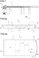
- FIG 1 illustrates very schematically the general principle of the family optical guides within which an optical guide 1 in accordance with the invention is developed.
- These systems therefore comprise an optical guide 1 transporting a beam of light towards an eye 2 of a user.
- the optical system also comprises a light injection system 3, making it possible to inject light beams 3a into the optical guide 1 via an input zone 1a.
- the injection system 3 comprises a micro-display 4 on which are located point sources of light generating the light beams as well as collimation members 5 making it possible to inject several parallel light beams 3a into the optical guide 1.
- the input zone 1a is an inclined face of the optical guide 1.
- the injection of light by the injection system 3 is carried out by choosing an adequate angle for the inclination of this inclined face.
- the injection system 3 is perpendicular to the longitudinal extension of the optical guide 1.
- the input coupling into the optical guide is obtained by means of a coupling mirror 1c constituted by an inclined and metallized face of the optical guide 1.
- the inclination angles ⁇ 1 and ⁇ 2 are respectively 45° and 24° for a material of the PMMA type.
- the light beams injected into the optical guide 1 propagate by total internal reflection.
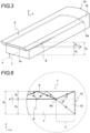
- FIG. 2a represents an exemplary embodiment, according to a longitudinal profile view, of the optical guide 1 according to the invention.
- the Figure 2a is a representation in an xy plane of an xyz space and the figure 2b is a representation according to a top view of said optical guide 1 in a zx plane.
- the optical guide 1 comprises a first guide element 6 arranged above a second guide element 7.
- the guide elements 6 and 7 advantageously have a single-piece lamellar shape and their respective faces facing each other are not contiguous over a portion of their length. A spacing 9, of small thickness, between the guide elements 6 and 7 thus makes it possible to produce an interface with a thin layer of air.
- the guide elements 6 and 7 are connected to each other over a complementary portion 1b of their length L by means of a continuity of material so as to constitute a single-piece or monobloc shape of the optical guide 1.
- the optical guide 1 also has at one of its longitudinal ends an optical reflection member.
- the latter is a cylindrical mirror 10a.
- the cylindrical mirror 10a thus achieves, with the complementary portion L, the optical coupling between the first guide element 6 and the second guide element 7.
- the light beams thus propagate first in the first guide element 6 before propagating in the second guide element 7 in an opposite direction. But in no case does a portion of the light rays propagate simultaneously in the two guide elements 6 and 7 and in the same direction of propagation.
- the light beams passing through the complementary portion 1b and reflecting on an internal face of the cylindrical mirror 10a therefore remain confined in the material constituting the guide elements 6 and 7 and do not pass through any interface or material discontinuity.
- the guide element 6 comprises at its longitudinal end opposite that comprising the cylindrical mirror 10, the entry zone 1a.
- the latter is for example produced by a simple inclined face extending orthogonally to the xy plane.
- the guide element 7 also integrates into an extraction zone, comprising for example an extraction mirror 11.
- the extraction zone comprises a cascade of three semi-reflecting extraction mirrors 11, making it possible to direct the light beams towards the eye 2.
- the propagation of the light therefore takes place independently in each guide element 6 and 7.
- the thickness e of the spacing 9 is however sufficient to avoid penetration of reflected light beams into said spacing 9 and thus avoid signal losses.
- the thickness e must therefore be as small as possible while avoiding the appearance of optical coupling between the guide elements 6 and 7.
- the thickness is advantageously between 0.1 mm and 0.2 mm.
- This end of the optical guide 1 illustrated for example in the figure 2b shows the arrangement of the cylindrical mirror 10a, with its internal face in contact with the common longitudinal end of the guide elements 6 and 7.
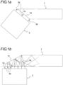
- FIG 3 is a perspective representation of the optical guide of the figure 2a or 2b .
- the guide elements 6 and 7 advantageously have a lamellar shape, of substantially the same length and width.
- the thickness e2 of the second guide element 7 is substantially equal to twice the thickness e1 of the first guide element 6.
- FIGS. 4a, 4b and 4c schematically illustrate examples of propagations of light beams in the optical guide 1 according to the invention, respectively along a plane yx, zx and zy.
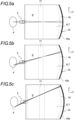
- Figures 5a, 5b and 5c schematically illustrate in a zx plane, examples of propagations of light beams in the optical guide 1 according to the invention, from different point sources located on the micro-display 4 associated with an inclined plane mirror 4a.
- Figure 5a illustrates a beam of light extending substantially along the central x-axis.
- the Figure 5b illustrates a beam of light extending in an intermediate direction and the figure 5c illustrates a beam of light extending in one extreme direction.
- the optical guide 1 is advantageously integrated into an optical display system close to the eye, such as a virtual or augmented reality headset or glasses.
- Such an optical system for near-eye display comprises, in addition to the optical guide 1 described above, the light injection system 3 for injecting light into said optical guide 1.
- the injection system 3 comprises the micro-display 4 for providing point sources.
- the injection system 3 makes it possible to obtain in the guide 1 parallel light beams in a given direction y and convergent in the plane zx.
- the injection system 3 comprises for this purpose optimized members, in particular of the lens type, to focus, in the zx plane, orthogonal to the yx plane, each beam of light on a curved focal surface, approximately spherical.
- This focal surface is located at the focal distance of the cylindrical mirror 10 for the central light beam or close to this focal distance for the other beams.
- the optimization is achieved for example by arranging lenses and machining special shapes such as free-form optical surfaces. This ensures that the light beams exiting the guide element 7 are completely parallel in the form of plane waves.
- the z-axis therefore corresponds to the vertical direction in which the field of vision is substantially enlarged in accordance with the invention.
- FIG. 6 illustrates schematically, with an enlargement of the Figure 2a , the minimum ⁇ and maximum ⁇ angles of incidence of a light beam propagating in an optical guide 1 according to the invention.
- the first guide element 6 and the second guide element 7 have a length of between 40 mm and 50 mm, the width of said guide elements 6 and 7 being identical. and between 35 mm and 45 mm. These dimensions are, for example, particularly suitable for integration into glasses.
- the optical guide has a thickness e3 of between 4 mm and 7 mm.
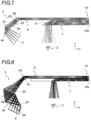
- FIG 7 schematically illustrates an embodiment of an optical system in which the light injection system 3 comprises two lenses 5a, 5b.
- the latter advantageously have three free-form optical surfaces S1, S2, S3 associated with an inclined plane mirror 4a.
- FIG 8 schematically illustrates an embodiment of an optical system in which the light injection system 3 comprises a free-form prism 3b in one piece.
- the free-form prism 3b has on the one hand four free-form optical surfaces S5, S6, S7, S8, two of which S5, S8 work in transmission, while the other two S7, S6 work in reflection and on the other hand, a lens 5c having a free-form optical surface S4.
- the light injection system 3 comprises two free-form mirrors S9 and S10 and a lens 5d having a free-form optical surface as well as a spherical lens 5e.
- the latter has one or two spherical faces.
- the spherical lens 5e has a flat face making it easier to position it relative to the optical guide 1.
- 5d and 5e lenses are made of different materials.
- One material is, for example, optical glass and the other material is, for example, a plastic or polymer. This results in two free-form surfaces that function in reflection, at least one free-form surface that functions in transmission, and a spherical surface that functions in transmission.
- the lens 5d has a free-form surface and a spherical face which is contiguous with the spherical face of the spherical lens 5e. The latter then has a second flat face.
- the lenses 5d and 5e are not contiguous.
- the lens 5d then has free-form faces and the spherical lens 5e has a spherical face and a flat face.
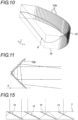
- FIG 10 is a partial representation of another exemplary embodiment of an optical guide 1, used in an optical system which is not part of the invention.
- This optical system comprises a light injection system 3 in which
- the cylindrical mirror 10a is replaced by sawtooth-shaped micro-reflectors 10b.
- the latter illustrated in more detail in figure 11 , advantageously have a height h of between 0.2 mm and 1 mm and are distributed according to a cylindrical arrangement with a radius of 42.8 mm.
- Two consecutive faces forming such a sawtooth advantageously have a mutual angle of between 89.8° and 90.2° and preferably equal to 90°.
- the optical reflection optical member is therefore made up of micro-reflectors 10b arranged in a cylindrical profile at the free end of the portion 1b.
- the sawtooth-shaped micro-reflectors 10b are advantageously metallized and produced in the cylindrical free end of the portion 1b, either by molding or by machining.
- the light injection system 3 which includes the micro-display 4 for providing point sources of light, also includes three aspherical lenses 5f, 5g, 5i, arranged to have six aspherical optical surfaces and a spherical lens 5h which has at least one spherical surface.
- the aspherical lenses 5f, 5g, 5i and the spherical lens 5h have a symmetry of revolution and are made for at least one of them with a constituent material different from that of the others.
- the light injection system 3 which includes the microdisplay 4 for providing point sources of light, also includes eight spherical lenses 5j, 5k, 5l, 5m, 5n, 5o, 5p, 5q.
- the spherical lenses 5j, 5k, 5l, 5m, 5n, 5o, 5p, 5q therefore have a symmetry of revolution, are made of optical glasses or a combination of optical glasses and plastics/polymers so as to produce an assembly of which at least one lens is made with a constituent material different from that of the other lenses.
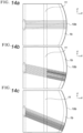
- FIGS. 14a, 14b and 14c schematically illustrate in a zx plane, examples of propagation of light beams in the form of plane waves in an optical guide 1 illustrated in particular in Figures 10 , 12 and 13
- FIG 15 is an illustration of an enlargement of a system or guide light extraction system arranged in an optical guide 1 according to the invention.
- the extraction guide is advantageously made up of a succession of semi-reflecting mirrors 11.
Landscapes
- Physics & Mathematics (AREA)
- General Physics & Mathematics (AREA)
- Optics & Photonics (AREA)
- Optical Couplings Of Light Guides (AREA)
- Light Guides In General And Applications Therefor (AREA)
- Lenses (AREA)
- Eye Examination Apparatus (AREA)
Claims (15)
- Lichtwellenleiter (1) für eine Anzeigevorrichtung in der Nähe des Auges, der Folgendes umfasst:- ein erstes Leiterelement (6) mit einem Eintrittsbereich, um einen Lichtstrahl in diesen zu injizieren,- ein zweites Leiterelement (7) mit einem Austrittsbereich, um den Lichtstrahl daraus zu extrahieren, wobei das erste Leiterelement (6) dem zweiten Leiterelement (7) überlagert ist, und- ein optisches Kopplungssystem zwischen dem ersten Leiterelement (6) und dem zweiten Leiterelement (7),- wobei das erste und das zweite Leiterelement (6, 7) über einen ersten Längenabschnitt einen gegenseitigen Abstand (9) aufweisen, um eine dünne Luftschicht zwischen den Leiterelementen (6, 7) zu begrenzen, die sich zwischen einem ersten Längsende der Leiterelemente (6, 7) erstreckt und das optische Kopplungssystem so dick ist, dass es verhindert, dass reflektierte Lichtstrahlen in den Abstand eindringen, dadurch gekennzeichnet, dass:- das optische Kopplungssystem, das sich an einem zweiten Längsende des ersten und zweiten Leiterelements (6, 7) befindet, einen einteiligen Abschnitt (1b) der Leiterelemente (6, 7) umfasst, der mit einem optischen Reflexionsorgan (10) verbunden ist, um die Lichtstrahlen von dem Eintrittsbereich zum Austrittsbereich weiterzuleiten, wobei das optische Reflexionsorgan (10) ein zylindrischer Spiegel (10a) ist, der die zylindrische Endfläche des Abschnitts (1b) bedeckt.
- Lichtwellenleiter (1) nach Anspruch 1, dadurch gekennzeichnet, dass die Dicke des Abstands (9) zwischen den Leiterelementen (6, 7) zwischen 0,1 mm und 0,2 mm beträgt.
- Lichtwellenleiter (1) nach Anspruch 1 oder 2, dadurch gekennzeichnet, dass das erste Leiterelement (6) den Eintrittsbereich an seinem ersten freien Längsende in Form einer geneigten Fläche (1a) aufweist.
- Lichtwellenleiter (1) nach einem der Ansprüche 1 bis 3, dadurch gekennzeichnet, dass der Austrittsbereich mit einem Lichtextraktionssystem versehen ist, das mindestens einen Extraktionsspiegel (11) umfasst.
- Lichtwellenleiter (1) nach einem der Ansprüche 1 bis 4, dadurch gekennzeichnet, dass der Austrittsbereich mit einem Lichtextraktionssystem versehen ist, das eine Folge von mehreren teilreflektierenden Extraktionsspiegeln (11) umfasst, die eine Extraktionsleitung bilden.
- Lichtwellenleiter (1) nach einem der Ansprüche 1 bis 5, dadurch gekennzeichnet, dass das zweite Leiterelement (7) eine Dicke e2 aufweist, die mit der Dicke e1 des ersten Leiterelements (6) im Verhältnis: e2 = e1 (tanβ / tanα) verbunden ist, wobei α und β jeweils der minimale und maximale Einfallswinkel der in das erste Leiterelement (6) injizierten Lichtstrahlen sind.
- Lichtwellenleiter (1) nach einem der Ansprüche 1 bis 6, dadurch gekennzeichnet, dass das erste Leiterelement (6) und das zweite Leiterelement (7) eine Länge zwischen 40 mm und 50 mm aufweisen, wobei die Breite der Leiterelemente (6, 7) identisch ist und zwischen 35 mm und 45 mm liegt.
- Lichtwellenleiter (1) nach einem der Ansprüche 1 bis 7, dadurch gekennzeichnet, dass er eine Dicke e3 zwischen 4 mm und 7 mm aufweist.
- Lichtwellenleiter (1) nach einem der Ansprüche 1 bis 8, dadurch gekennzeichnet, dass die Leiterelemente (6, 7) aus demselben Material, der Art wie PMMA, bestehen.
- Optisches System zur Anzeige in Augennähe, das folgendes umfasst:- einen Lichtwellenleiter (1) nach Anspruch 1 und 2, und- ein Lichtinjektionssystem (3) zum Injizieren von Licht in den Lichtwellenleiter (1), wobei das Injektionssystem (3) eine Mikroanzeige (4) zum Bereitstellen von Punktlichtquellen umfasst und man durch das Injektionssystem (3) in dem Leiter (1) Lichtstrahlen erhält, die in einer gegebenen Richtung y parallel sind und in einer xz-Ebene orthogonal zu der Richtung y konvergieren.
- Optisches System zur augennahen Anzeige nach Anspruch 10, dadurch gekennzeichnet, dass das Injektionssystem (3) Organe umfasst, die optimiert sind, um in einer zx-Ebene, orthogonal zur yx-Ebene, jeden Lichtstrahl auf eine gebogene Brennfläche zu fokussieren, die im Wesentlichen in der Fokusweite des Zylinderspiegels (10a) liegt.
- Optisches System nach Anspruch 11, dadurch gekennzeichnet, dass das Lichtinjektionssystem (3) zwei Linsen (5a, 5b) mit drei frei geformten optischen Oberflächen (S1, S2, S3) und einen Planspiegel (4a) umfasst.
- Optisches System nach Anspruch 11, dadurch gekennzeichnet, dass das Lichtinjektionssystem (3) zwei Freiformspiegel (S9, S10) und eine Linse (5d) mit mindestens einer optischen Freiformfläche sowie eine sphärische Linse (5e) umfasst.
- Optisches System nach Anspruch 11, dadurch gekennzeichnet, dass das Lichtinjektionssystem (3) ein einteiliges Freiformprisma (3b) mit vier optischen Freiformflächen (S5, S6, S7, S8), von denen zwei (S5, S8) in der Übertragung und die anderen beiden (S7, S6) in Reflexion arbeiten, und eine Linse (5c) mit einer optischen Freiformfläche (S4) umfasst.
- Helm oder Brille für virtuelle oder erweiterte Realität, dadurch gekennzeichnet, dass in diesem, dieser oder diesen ein optisches System gemäß einem der Ansprüche 10 bis 14 integriert ist.
Applications Claiming Priority (3)
| Application Number | Priority Date | Filing Date | Title |
|---|---|---|---|
| FR1650351A FR3046850B1 (fr) | 2016-01-15 | 2016-01-15 | Guide optique ameliore et systeme optique comportant un tel guide optique |
| FR1661067A FR3046851B1 (fr) | 2016-01-15 | 2016-11-15 | Guide optique ameliore et systeme optique |
| PCT/FR2017/050073 WO2017121967A2 (fr) | 2016-01-15 | 2017-01-12 | Guide optique amélioré et système optique |
Publications (3)
| Publication Number | Publication Date |
|---|---|
| EP3403023A2 EP3403023A2 (de) | 2018-11-21 |
| EP3403023B1 true EP3403023B1 (de) | 2025-03-05 |
| EP3403023C0 EP3403023C0 (de) | 2025-03-05 |
Family
ID=55361876
Family Applications (1)
| Application Number | Title | Priority Date | Filing Date |
|---|---|---|---|
| EP17712191.0A Active EP3403023B1 (de) | 2016-01-15 | 2017-01-12 | Verbesserter lichtleiter und optisches system |
Country Status (6)
| Country | Link |
|---|---|
| US (2) | US10718946B2 (de) |
| EP (1) | EP3403023B1 (de) |
| JP (1) | JP6800233B2 (de) |
| CN (1) | CN108474542B (de) |
| FR (2) | FR3046850B1 (de) |
| WO (1) | WO2017121967A2 (de) |
Families Citing this family (15)
| Publication number | Priority date | Publication date | Assignee | Title |
|---|---|---|---|---|
| CN112805997A (zh) * | 2018-06-30 | 2021-05-14 | 石井房雄 | 增强现实(ar)显示器 |
| CN112147782B (zh) | 2019-06-26 | 2022-09-30 | 中强光电股份有限公司 | 光学镜头及头戴式显示设备 |
| EP3757658B1 (de) * | 2019-06-26 | 2023-02-22 | Coretronic Corporation | Optische linse und kopfmontierte anzeigevorrichtung |
| TWI858170B (zh) * | 2019-10-23 | 2024-10-11 | 以色列商魯姆斯有限公司 | 採用散光光學器件和像差補償的顯示器 |
| CA3155597C (en) * | 2019-12-08 | 2023-02-14 | Lumus Ltd. | Optical systems with compact image projector |
| EP4022382B1 (de) * | 2020-08-23 | 2023-10-25 | Lumus Ltd. | Optisches system zur zweidimensionalen erweiterung eines bildes mit reduzierung von lichtreflexen und geisterbildern im wellenleiter |
| CN114114518A (zh) * | 2020-08-28 | 2022-03-01 | 中强光电股份有限公司 | 光波导、光波导的制作方法以及头戴式显示装置 |
| DE202021104723U1 (de) | 2020-09-11 | 2021-10-18 | Lumus Ltd. | An ein optisches Lichtleiterelement gekoppelter Bildprojektor |
| CN112230435A (zh) * | 2020-11-19 | 2021-01-15 | 维沃移动通信有限公司 | 光学系统和可穿戴设备 |
| CN112269266B (zh) * | 2020-11-19 | 2022-11-18 | 维沃移动通信有限公司 | 光学系统和可穿戴设备 |
| CN115373064A (zh) | 2021-05-20 | 2022-11-22 | 中强光电股份有限公司 | 光波导 |
| CN113391393B (zh) * | 2021-06-28 | 2025-09-09 | 维沃移动通信有限公司 | 光学系统和可穿戴设备 |
| US11852822B2 (en) * | 2021-07-09 | 2023-12-26 | Realwear, Inc. | Convertible waveguide optical engine assembly for head-mounted device |
| US11940627B2 (en) * | 2021-07-09 | 2024-03-26 | Realwear, Inc. | Opaque waveguide optical engine assembly for head-mounted device |
| FR3153162A1 (fr) * | 2023-09-18 | 2025-03-21 | Optiive | Systeme de guide optique amélioré et dispositif d’affichage pres de l’œil comportant un tel systeme |
Citations (2)
| Publication number | Priority date | Publication date | Assignee | Title |
|---|---|---|---|---|
| JP2004158336A (ja) * | 2002-11-07 | 2004-06-03 | Advanced Display Inc | 面状光源装置および該装置を用いた液晶表示装置 |
| EP3292432A1 (de) * | 2015-04-23 | 2018-03-14 | LEIA Inc. | Gitterbasierte hintergrundbeleuchtung mit zwei lichtleitern und elektronische anzeige damit |
Family Cites Families (77)
| Publication number | Priority date | Publication date | Assignee | Title |
|---|---|---|---|---|
| US212400A (en) | 1879-02-18 | Improvement in adjusting-straps for garments | ||
| US4761056A (en) * | 1987-03-27 | 1988-08-02 | Kaiser Aerospace And Electronics Corporation | Compact helmet mounted display |
| EP0641049B1 (de) * | 1993-08-31 | 1998-10-28 | Fujitsu Limited | Optischer Halbleitervorrichtung und Herstellungsverfahren |
| US5986790A (en) * | 1996-03-05 | 1999-11-16 | Fuji Xerox, Co., Ltd. | Light source for optical communication, optical transceiver and optical communication network |
| US5886822A (en) * | 1996-10-08 | 1999-03-23 | The Microoptical Corporation | Image combining system for eyeglasses and face masks |
| US5913594A (en) * | 1997-02-25 | 1999-06-22 | Iimura; Keiji | Flat panel light source device and passive display device utilizing the light source device |
| JP4921634B2 (ja) * | 2000-01-31 | 2012-04-25 | グーグル インコーポレイテッド | 表示装置 |
| US6560385B2 (en) * | 2001-05-24 | 2003-05-06 | General Electric Company | Fiber optic prism coupler, coupling arrangement and fabrication method |
| GB0118866D0 (en) * | 2001-08-02 | 2001-09-26 | Cambridge 3D Display Ltd | Shaped taper flat panel display |
| WO2003027754A1 (en) * | 2001-09-25 | 2003-04-03 | Cambridge Flat Projection Displays | Flat-panel projection display |
| IL148804A (en) * | 2002-03-21 | 2007-02-11 | Yaacov Amitai | Optical device |
| ITTO20020625A1 (it) * | 2002-07-17 | 2004-01-19 | Fiat Ricerche | Guida di luce per dispositivi di visualizzazione di tipo "head-mounted" o "head-up" |
| JP2004095390A (ja) * | 2002-08-30 | 2004-03-25 | Fujitsu Display Technologies Corp | 照明装置及び表示装置 |
| US7417782B2 (en) * | 2005-02-23 | 2008-08-26 | Pixtronix, Incorporated | Methods and apparatus for spatial light modulation |
| JP4076917B2 (ja) * | 2003-06-27 | 2008-04-16 | 富士通株式会社 | 平面光回路構造を有する光波長スイッチ |
| CN100480777C (zh) * | 2003-12-10 | 2009-04-22 | 松下电器产业株式会社 | 光学元件、激光光源和二维图像形成装置 |
| FR2866123B1 (fr) * | 2004-02-10 | 2007-10-12 | Zile Liu | Procede et dispositif pour la creation d'images retiniennes utilisant le stigmatisme des deux foyers d'un dioptre sensiblement elliptique |
| JP4984452B2 (ja) * | 2005-07-25 | 2012-07-25 | ソニー株式会社 | 空間光変調光学装置とこれを用いた虚像表示装置及び投射型画像表示装置 |
| ATE434200T1 (de) * | 2005-12-29 | 2009-07-15 | Fiat Ricerche | Optisches system zur bildübertragung, besonders für projektionsgeräte der kopfmontierten art |
| IL173715A0 (en) * | 2006-02-14 | 2007-03-08 | Lumus Ltd | Substrate-guided imaging lens |
| FR2906896B1 (fr) * | 2006-10-04 | 2009-01-23 | Commissariat Energie Atomique | Dispositif de couplage ameliore entre une fibre optique et un guide optique integre sur un substrat. |
| WO2008129539A2 (en) * | 2007-04-22 | 2008-10-30 | Lumus Ltd. | A collimating optical device and system |
| CN101779148B (zh) * | 2007-06-14 | 2014-06-25 | 艾利丹尼森公司 | 受照图形和信息显示器 |
| US20110001901A1 (en) * | 2007-12-05 | 2011-01-06 | Solomon Jeffrey L | Dual lightguide |
| US7949213B2 (en) * | 2007-12-07 | 2011-05-24 | Qualcomm Mems Technologies, Inc. | Light illumination of displays with front light guide and coupling elements |
| DE102008005817A1 (de) * | 2008-01-24 | 2009-07-30 | Carl Zeiss Ag | Optisches Anzeigegerät |
| US8638483B2 (en) * | 2008-09-17 | 2014-01-28 | Konica Minolta Holdings, Inc. | Image display device and head-mounted display |
| JP4674634B2 (ja) * | 2008-12-19 | 2011-04-20 | ソニー株式会社 | 頭部装着型ディスプレイ |
| FR2941786B1 (fr) | 2009-02-03 | 2011-04-29 | Laster | Dispositif portable d'affichage tete haute et de realite augmentee |
| FR2943118B1 (fr) * | 2009-03-12 | 2012-07-20 | Valeo Vision Sas | Dispositif optique, notamment pour vehicule automobile, tel qu'un dispositif d'eclairage ou de signalisation |
| JP5402293B2 (ja) * | 2009-06-22 | 2014-01-29 | ソニー株式会社 | 頭部装着型ディスプレイ、及び、頭部装着型ディスプレイにおける画像表示方法 |
| JP5104823B2 (ja) * | 2009-07-29 | 2012-12-19 | 株式会社島津製作所 | 表示装置 |
| US11320571B2 (en) * | 2012-11-16 | 2022-05-03 | Rockwell Collins, Inc. | Transparent waveguide display providing upper and lower fields of view with uniform light extraction |
| WO2011050233A1 (en) * | 2009-10-24 | 2011-04-28 | 3M Innovative Properties Company | Immersed asymmetric reflector with reduced color |
| FR2954923B1 (fr) * | 2010-01-06 | 2012-05-04 | Delphi Tech Inc | Dispositif diffractif de signalisation pour retroviseur avec affichage 2d/3d |
| US8488246B2 (en) * | 2010-02-28 | 2013-07-16 | Osterhout Group, Inc. | See-through near-eye display glasses including a curved polarizing film in the image source, a partially reflective, partially transmitting optical element and an optically flat film |
| DE102010040962A1 (de) * | 2010-09-17 | 2012-03-22 | Carl Zeiss Ag | Anzeigevorrichtung mit einer auf den Kopf eines Benutzers aufsetzbaren Haltevorrichtung |
| JP2012098324A (ja) * | 2010-10-29 | 2012-05-24 | Seiko Epson Corp | 導光板及びこれを備える虚像表示装置 |
| WO2013028467A1 (en) * | 2011-08-19 | 2013-02-28 | Barnesandnoble.Com Llc | Planar front illumination system having a light guide with micro scattering features formed thereon and method of manufacturing the same |
| US9013793B2 (en) * | 2011-09-21 | 2015-04-21 | Google Inc. | Lightweight eyepiece for head mounted display |
| FR2983976B1 (fr) | 2011-12-13 | 2017-10-20 | Optinvent | Guide optique a elements de guidage superposes et procede de fabrication |
| EP2808725B1 (de) * | 2012-01-24 | 2018-09-26 | Sony Corporation | Kopfmontierte anzeigevorrichtung mit lichtabschirmelement |
| JP6145966B2 (ja) * | 2012-05-09 | 2017-06-14 | ソニー株式会社 | 表示装置 |
| EP2850471B1 (de) * | 2012-05-18 | 2020-08-26 | RealD Spark, LLC | Gerichtet beleuchtete wellenleiteranordnung |
| US9188731B2 (en) * | 2012-05-18 | 2015-11-17 | Reald Inc. | Directional backlight |
| WO2014115330A1 (ja) * | 2013-01-28 | 2014-07-31 | 富士通株式会社 | レーザ装置、光変調装置及び光半導体素子 |
| JP6123342B2 (ja) * | 2013-02-20 | 2017-05-10 | ソニー株式会社 | 表示装置 |
| US8915635B2 (en) * | 2013-03-13 | 2014-12-23 | Hewlett-Packard Development Company, L.P. | Backlight having dual collimating reflectors |
| KR20150128719A (ko) * | 2013-03-13 | 2015-11-18 | 휴렛-팩커드 디벨롭먼트 컴퍼니, 엘.피. | 콜리메이팅 반사체를 갖는 백라이트 |
| JP2014225725A (ja) * | 2013-05-15 | 2014-12-04 | ソニー株式会社 | 表示装置及び画像表示装置用光源 |
| WO2014198619A1 (en) * | 2013-06-14 | 2014-12-18 | Koninklijke Philips N.V. | Light emitting device |
| WO2015001839A1 (ja) * | 2013-07-04 | 2015-01-08 | ソニー株式会社 | 表示装置 |
| FR3008497B1 (fr) * | 2013-07-10 | 2015-08-07 | Univ Strasbourg | Dispositif pour compenser la derive d'un dephasage d'un modulateur d'etat de polarisation d'un faisceau lumineux |
| JP6337465B2 (ja) * | 2013-12-26 | 2018-06-06 | セイコーエプソン株式会社 | 虚像表示装置 |
| JP2015148782A (ja) * | 2014-02-10 | 2015-08-20 | ソニー株式会社 | 画像表示装置及び表示装置 |
| JP6314518B2 (ja) * | 2014-02-10 | 2018-04-25 | ソニー株式会社 | 画像表示装置及び表示装置 |
| JP6391952B2 (ja) * | 2014-03-17 | 2018-09-19 | ソニー株式会社 | 表示装置及び光学装置 |
| JP2015184561A (ja) * | 2014-03-25 | 2015-10-22 | ソニー株式会社 | 導光装置、画像表示装置及び表示装置 |
| JP2015184560A (ja) * | 2014-03-25 | 2015-10-22 | ソニー株式会社 | 導光装置、画像表示装置及び表示装置 |
| US9557466B2 (en) * | 2014-07-30 | 2017-01-31 | Leia, Inc | Multibeam diffraction grating-based color backlighting |
| JP6690550B2 (ja) * | 2014-11-27 | 2020-04-28 | ソニー株式会社 | 光学装置及び表示装置 |
| US10437064B2 (en) * | 2015-01-12 | 2019-10-08 | Digilens Inc. | Environmentally isolated waveguide display |
| CN104614858B (zh) * | 2015-01-25 | 2017-02-22 | 上海理湃光晶技术有限公司 | 增强现实的锯齿结构平面波导目视光学显示器件 |
| EP3062142B1 (de) * | 2015-02-26 | 2018-10-03 | Nokia Technologies OY | Vorrichtung für augennahe Anzeige |
| JP6892213B2 (ja) * | 2015-04-30 | 2021-06-23 | ソニーグループ株式会社 | 表示装置及び表示装置の初期設定方法 |
| JP6779984B2 (ja) * | 2015-09-05 | 2020-11-04 | レイア、インコーポレイテッドLeia Inc. | 集光型バックライトおよびそれを使用するニアアイディスプレイシステム |
| JP6987044B2 (ja) * | 2015-09-05 | 2021-12-22 | レイア、インコーポレイテッドLeia Inc. | 二面コリメータ、および同コリメータを用いた格子ベースの背面照明を使用した3d電子ディスプレイ |
| JP6851369B2 (ja) * | 2015-09-05 | 2021-03-31 | レイア、インコーポレイテッドLeia Inc. | ヘッドトラッキングを備えたマルチビーム回折格子型ディスプレイ |
| EP3345041B1 (de) * | 2015-09-05 | 2025-06-25 | LEIA Inc. | Zweirichtungskollimator |
| DE102015122055B4 (de) * | 2015-12-17 | 2018-08-30 | Carl Zeiss Ag | Optisches System sowie Verfahren zum Übertragen eines Quellbildes |
| JP6988803B2 (ja) * | 2016-07-12 | 2022-01-05 | ソニーグループ株式会社 | 調光装置、画像表示装置及び表示装置 |
| WO2018067725A1 (en) * | 2016-10-05 | 2018-04-12 | Leia Inc. | Transparent display and method |
| IL307602A (en) * | 2017-02-23 | 2023-12-01 | Magic Leap Inc | Variable focus virtual imagers based on polarization conversion |
| CN115576048A (zh) * | 2017-03-21 | 2023-01-06 | 奇跃公司 | 用于组合视场的具有不同衍射光栅的堆叠波导 |
| US10175489B1 (en) * | 2017-07-05 | 2019-01-08 | Microsoft Technology Licensing, Llc | Compact optical system with MEMS scanners for image generation and object tracking |
| CN107219685B (zh) * | 2017-07-28 | 2020-07-31 | 京东方科技集团股份有限公司 | 显示装置及显示装置的显示方法 |
| KR102805316B1 (ko) * | 2018-01-04 | 2025-05-09 | 매직 립, 인코포레이티드 | 무기 재료들을 포함하는 중합체 구조들에 기반한 광학 엘리먼트들 |
-
2016
- 2016-01-15 FR FR1650351A patent/FR3046850B1/fr active Active
- 2016-11-15 FR FR1661067A patent/FR3046851B1/fr active Active
-
2017
- 2017-01-12 CN CN201780006626.5A patent/CN108474542B/zh active Active
- 2017-01-12 EP EP17712191.0A patent/EP3403023B1/de active Active
- 2017-01-12 US US16/069,256 patent/US10718946B2/en active Active
- 2017-01-12 WO PCT/FR2017/050073 patent/WO2017121967A2/fr not_active Ceased
- 2017-01-12 JP JP2018537439A patent/JP6800233B2/ja active Active
-
2020
- 2020-06-16 US US16/902,843 patent/US11156840B2/en active Active
Patent Citations (2)
| Publication number | Priority date | Publication date | Assignee | Title |
|---|---|---|---|---|
| JP2004158336A (ja) * | 2002-11-07 | 2004-06-03 | Advanced Display Inc | 面状光源装置および該装置を用いた液晶表示装置 |
| EP3292432A1 (de) * | 2015-04-23 | 2018-03-14 | LEIA Inc. | Gitterbasierte hintergrundbeleuchtung mit zwei lichtleitern und elektronische anzeige damit |
Also Published As
| Publication number | Publication date |
|---|---|
| JP6800233B2 (ja) | 2020-12-16 |
| WO2017121967A2 (fr) | 2017-07-20 |
| EP3403023A2 (de) | 2018-11-21 |
| CN108474542B (zh) | 2022-06-07 |
| FR3046850A1 (fr) | 2017-07-21 |
| CN108474542A (zh) | 2018-08-31 |
| FR3046851A1 (fr) | 2017-07-21 |
| US20190033598A1 (en) | 2019-01-31 |
| WO2017121967A3 (fr) | 2017-10-19 |
| JP2019509508A (ja) | 2019-04-04 |
| US11156840B2 (en) | 2021-10-26 |
| FR3046851B1 (fr) | 2019-07-26 |
| US20200310136A1 (en) | 2020-10-01 |
| FR3046850B1 (fr) | 2018-01-26 |
| EP3403023C0 (de) | 2025-03-05 |
| US10718946B2 (en) | 2020-07-21 |
Similar Documents
| Publication | Publication Date | Title |
|---|---|---|
| EP3403023B1 (de) | Verbesserter lichtleiter und optisches system | |
| EP3074809B1 (de) | Vorrichtung zur erweiterung der austrittspupille und scheinwerferanzeige mit dieser vorrichtung | |
| EP3128226B1 (de) | Leuchtmodul aus transparentem material mit zwei reflexionsseiten | |
| EP2277074B1 (de) | Informative brille | |
| EP3063468B1 (de) | Optischer leiter zur erzeugung zwei leuchtender prägungen | |
| EP2695017B1 (de) | Vorrichtung zur optischen wellenleitung und verfahren zur herstellung einer solchen vorrichtung | |
| EP2703852B1 (de) | Lichtleitungslage mit Eingangskoppelung und Diopter mit Fresnel-Oberfläche | |
| EP3132312B1 (de) | System zur anzeige eines bildes auf einer windschutzscheibe | |
| FR2698454A1 (fr) | Système optique de superposition de données sur une scène. | |
| FR2995089A1 (fr) | Dispositif optique et procede de fabrication d'un tel dispositif | |
| EP2607778A1 (de) | Beleuchtungssystem für Scheinwerfer, insbesondere eines Kraftfahrzeugs | |
| FR2634907A1 (fr) | Dispositif optique multispectral a miroirs | |
| FR2950672A1 (fr) | Module optique avec plieuse formee par un dioptre materiau transparent / air | |
| EP0096615B1 (de) | Optischer Schalter | |
| EP2828694B1 (de) | System zum einkoppeln von licht in einen wellenleiter, wellenleitervorrichtung und anordnung zum einkoppeln von licht in einen wellenleiter | |
| EP3601678B1 (de) | Vorrichtung zur wellenenergiesteuerung | |
| WO2025061700A1 (fr) | Systeme de guide optique amélioré et dispositif d'affichage pres de l'œil comportant un tel systeme | |
| WO2017191052A1 (fr) | Dispositif de génération d'images et afficheur tête-haute comportant un tel dispositif | |
| EP2423720B1 (de) | Wellenlängen-abstimmbares optisches Filter und reflektierendes Bauteil | |
| EP3841325A1 (de) | Optisches system | |
| FR3061777A1 (fr) | Coupleur multi sources lumineuses pour guide optique |
Legal Events
| Date | Code | Title | Description |
|---|---|---|---|
| STAA | Information on the status of an ep patent application or granted ep patent |
Free format text: STATUS: UNKNOWN |
|
| STAA | Information on the status of an ep patent application or granted ep patent |
Free format text: STATUS: THE INTERNATIONAL PUBLICATION HAS BEEN MADE |
|
| PUAI | Public reference made under article 153(3) epc to a published international application that has entered the european phase |
Free format text: ORIGINAL CODE: 0009012 |
|
| STAA | Information on the status of an ep patent application or granted ep patent |
Free format text: STATUS: REQUEST FOR EXAMINATION WAS MADE |
|
| 17P | Request for examination filed |
Effective date: 20180613 |
|
| AK | Designated contracting states |
Kind code of ref document: A2 Designated state(s): AL AT BE BG CH CY CZ DE DK EE ES FI FR GB GR HR HU IE IS IT LI LT LU LV MC MK MT NL NO PL PT RO RS SE SI SK SM TR |
|
| AX | Request for extension of the european patent |
Extension state: BA ME |
|
| DAV | Request for validation of the european patent (deleted) | ||
| DAX | Request for extension of the european patent (deleted) | ||
| STAA | Information on the status of an ep patent application or granted ep patent |
Free format text: STATUS: EXAMINATION IS IN PROGRESS |
|
| 17Q | First examination report despatched |
Effective date: 20200513 |
|
| GRAP | Despatch of communication of intention to grant a patent |
Free format text: ORIGINAL CODE: EPIDOSNIGR1 |
|
| STAA | Information on the status of an ep patent application or granted ep patent |
Free format text: STATUS: GRANT OF PATENT IS INTENDED |
|
| INTG | Intention to grant announced |
Effective date: 20241015 |
|
| GRAS | Grant fee paid |
Free format text: ORIGINAL CODE: EPIDOSNIGR3 |
|
| GRAA | (expected) grant |
Free format text: ORIGINAL CODE: 0009210 |
|
| STAA | Information on the status of an ep patent application or granted ep patent |
Free format text: STATUS: THE PATENT HAS BEEN GRANTED |
|
| AK | Designated contracting states |
Kind code of ref document: B1 Designated state(s): AL AT BE BG CH CY CZ DE DK EE ES FI FR GB GR HR HU IE IS IT LI LT LU LV MC MK MT NL NO PL PT RO RS SE SI SK SM TR |
|
| REG | Reference to a national code |
Ref country code: GB Ref legal event code: FG4D Free format text: NOT ENGLISH |
|
| REG | Reference to a national code |
Ref country code: CH Ref legal event code: EP |
|
| REG | Reference to a national code |
Ref country code: IE Ref legal event code: FG4D Free format text: LANGUAGE OF EP DOCUMENT: FRENCH |
|
| REG | Reference to a national code |
Ref country code: DE Ref legal event code: R096 Ref document number: 602017088150 Country of ref document: DE |
|
| U01 | Request for unitary effect filed |
Effective date: 20250305 |
|
| U07 | Unitary effect registered |
Designated state(s): AT BE BG DE DK EE FI FR IT LT LU LV MT NL PT RO SE SI Effective date: 20250311 |
|
| PG25 | Lapsed in a contracting state [announced via postgrant information from national office to epo] |
Ref country code: RS Free format text: LAPSE BECAUSE OF FAILURE TO SUBMIT A TRANSLATION OF THE DESCRIPTION OR TO PAY THE FEE WITHIN THE PRESCRIBED TIME-LIMIT Effective date: 20250605 |
|
| PG25 | Lapsed in a contracting state [announced via postgrant information from national office to epo] |
Ref country code: ES Free format text: LAPSE BECAUSE OF FAILURE TO SUBMIT A TRANSLATION OF THE DESCRIPTION OR TO PAY THE FEE WITHIN THE PRESCRIBED TIME-LIMIT Effective date: 20250305 |
|
| PG25 | Lapsed in a contracting state [announced via postgrant information from national office to epo] |
Ref country code: NO Free format text: LAPSE BECAUSE OF FAILURE TO SUBMIT A TRANSLATION OF THE DESCRIPTION OR TO PAY THE FEE WITHIN THE PRESCRIBED TIME-LIMIT Effective date: 20250605 |
|
| PG25 | Lapsed in a contracting state [announced via postgrant information from national office to epo] |
Ref country code: HR Free format text: LAPSE BECAUSE OF FAILURE TO SUBMIT A TRANSLATION OF THE DESCRIPTION OR TO PAY THE FEE WITHIN THE PRESCRIBED TIME-LIMIT Effective date: 20250305 |
|
| PG25 | Lapsed in a contracting state [announced via postgrant information from national office to epo] |
Ref country code: GR Free format text: LAPSE BECAUSE OF FAILURE TO SUBMIT A TRANSLATION OF THE DESCRIPTION OR TO PAY THE FEE WITHIN THE PRESCRIBED TIME-LIMIT Effective date: 20250606 |
|
| PG25 | Lapsed in a contracting state [announced via postgrant information from national office to epo] |
Ref country code: SM Free format text: LAPSE BECAUSE OF FAILURE TO SUBMIT A TRANSLATION OF THE DESCRIPTION OR TO PAY THE FEE WITHIN THE PRESCRIBED TIME-LIMIT Effective date: 20250305 |
|
| PG25 | Lapsed in a contracting state [announced via postgrant information from national office to epo] |
Ref country code: PL Free format text: LAPSE BECAUSE OF FAILURE TO SUBMIT A TRANSLATION OF THE DESCRIPTION OR TO PAY THE FEE WITHIN THE PRESCRIBED TIME-LIMIT Effective date: 20250305 |
|
| PG25 | Lapsed in a contracting state [announced via postgrant information from national office to epo] |
Ref country code: CZ Free format text: LAPSE BECAUSE OF FAILURE TO SUBMIT A TRANSLATION OF THE DESCRIPTION OR TO PAY THE FEE WITHIN THE PRESCRIBED TIME-LIMIT Effective date: 20250305 |
|
| PG25 | Lapsed in a contracting state [announced via postgrant information from national office to epo] |
Ref country code: SK Free format text: LAPSE BECAUSE OF FAILURE TO SUBMIT A TRANSLATION OF THE DESCRIPTION OR TO PAY THE FEE WITHIN THE PRESCRIBED TIME-LIMIT Effective date: 20250305 |
|
| PG25 | Lapsed in a contracting state [announced via postgrant information from national office to epo] |
Ref country code: IS Free format text: LAPSE BECAUSE OF FAILURE TO SUBMIT A TRANSLATION OF THE DESCRIPTION OR TO PAY THE FEE WITHIN THE PRESCRIBED TIME-LIMIT Effective date: 20250705 |
|
| PLBE | No opposition filed within time limit |
Free format text: ORIGINAL CODE: 0009261 |
|
| STAA | Information on the status of an ep patent application or granted ep patent |
Free format text: STATUS: NO OPPOSITION FILED WITHIN TIME LIMIT |
|
| REG | Reference to a national code |
Ref country code: CH Ref legal event code: L10 Free format text: ST27 STATUS EVENT CODE: U-0-0-L10-L00 (AS PROVIDED BY THE NATIONAL OFFICE) Effective date: 20260114 |
|
| REG | Reference to a national code |
Ref country code: CH Ref legal event code: U11 Free format text: ST27 STATUS EVENT CODE: U-0-0-U10-U11 (AS PROVIDED BY THE NATIONAL OFFICE) Effective date: 20260201 |
|
| 26N | No opposition filed |
Effective date: 20251208 |
|
| U20 | Renewal fee for the european patent with unitary effect paid |
Year of fee payment: 10 Effective date: 20260127 |
|
| PGFP | Annual fee paid to national office [announced via postgrant information from national office to epo] |
Ref country code: GB Payment date: 20260127 Year of fee payment: 10 |
|
| PGFP | Annual fee paid to national office [announced via postgrant information from national office to epo] |
Ref country code: CH Payment date: 20260201 Year of fee payment: 10 |