EP3601678B1 - Vorrichtung zur wellenenergiesteuerung - Google Patents
Vorrichtung zur wellenenergiesteuerung Download PDFInfo
- Publication number
- EP3601678B1 EP3601678B1 EP18722109.8A EP18722109A EP3601678B1 EP 3601678 B1 EP3601678 B1 EP 3601678B1 EP 18722109 A EP18722109 A EP 18722109A EP 3601678 B1 EP3601678 B1 EP 3601678B1
- Authority
- EP
- European Patent Office
- Prior art keywords
- zone
- hydroelastic
- zones
- eff
- waves
- Prior art date
- Legal status (The legal status is an assumption and is not a legal conclusion. Google has not performed a legal analysis and makes no representation as to the accuracy of the status listed.)
- Not-in-force
Links
- 239000002131 composite material Substances 0.000 claims description 51
- 239000007788 liquid Substances 0.000 claims description 50
- 230000001902 propagating effect Effects 0.000 claims description 22
- 238000005452 bending Methods 0.000 claims description 16
- 239000000463 material Substances 0.000 claims description 11
- 238000007667 floating Methods 0.000 claims description 10
- 230000003287 optical effect Effects 0.000 claims description 8
- 239000011159 matrix material Substances 0.000 claims description 5
- 238000003306 harvesting Methods 0.000 claims 1
- 239000006185 dispersion Substances 0.000 description 8
- 239000013013 elastic material Substances 0.000 description 5
- 238000004519 manufacturing process Methods 0.000 description 5
- 230000005611 electricity Effects 0.000 description 3
- 230000005484 gravity Effects 0.000 description 2
- 230000000750 progressive effect Effects 0.000 description 2
- 238000011084 recovery Methods 0.000 description 2
- 229920000297 Rayon Polymers 0.000 description 1
- 241001080024 Telles Species 0.000 description 1
- 230000007547 defect Effects 0.000 description 1
- 238000005516 engineering process Methods 0.000 description 1
- 238000009434 installation Methods 0.000 description 1
- 238000012544 monitoring process Methods 0.000 description 1
- 239000002964 rayon Substances 0.000 description 1
- XLYOFNOQVPJJNP-UHFFFAOYSA-N water Substances O XLYOFNOQVPJJNP-UHFFFAOYSA-N 0.000 description 1
Images



Classifications
-
- E—FIXED CONSTRUCTIONS
- E02—HYDRAULIC ENGINEERING; FOUNDATIONS; SOIL SHIFTING
- E02B—HYDRAULIC ENGINEERING
- E02B3/00—Engineering works in connection with control or use of streams, rivers, coasts, or other marine sites; Sealings or joints for engineering works in general
- E02B3/04—Structures or apparatus for, or methods of, protecting banks, coasts, or harbours
- E02B3/06—Moles; Piers; Quays; Quay walls; Groynes; Breakwaters ; Wave dissipating walls; Quay equipment
- E02B3/062—Constructions floating in operational condition, e.g. breakwaters or wave dissipating walls
-
- E—FIXED CONSTRUCTIONS
- E02—HYDRAULIC ENGINEERING; FOUNDATIONS; SOIL SHIFTING
- E02B—HYDRAULIC ENGINEERING
- E02B9/00—Water-power plants; Layout, construction or equipment, methods of, or apparatus for, making same
- E02B9/08—Tide or wave power plants
-
- Y—GENERAL TAGGING OF NEW TECHNOLOGICAL DEVELOPMENTS; GENERAL TAGGING OF CROSS-SECTIONAL TECHNOLOGIES SPANNING OVER SEVERAL SECTIONS OF THE IPC; TECHNICAL SUBJECTS COVERED BY FORMER USPC CROSS-REFERENCE ART COLLECTIONS [XRACs] AND DIGESTS
- Y02—TECHNOLOGIES OR APPLICATIONS FOR MITIGATION OR ADAPTATION AGAINST CLIMATE CHANGE
- Y02A—TECHNOLOGIES FOR ADAPTATION TO CLIMATE CHANGE
- Y02A10/00—TECHNOLOGIES FOR ADAPTATION TO CLIMATE CHANGE at coastal zones; at river basins
- Y02A10/11—Hard structures, e.g. dams, dykes or breakwaters
-
- Y—GENERAL TAGGING OF NEW TECHNOLOGICAL DEVELOPMENTS; GENERAL TAGGING OF CROSS-SECTIONAL TECHNOLOGIES SPANNING OVER SEVERAL SECTIONS OF THE IPC; TECHNICAL SUBJECTS COVERED BY FORMER USPC CROSS-REFERENCE ART COLLECTIONS [XRACs] AND DIGESTS
- Y02—TECHNOLOGIES OR APPLICATIONS FOR MITIGATION OR ADAPTATION AGAINST CLIMATE CHANGE
- Y02E—REDUCTION OF GREENHOUSE GAS [GHG] EMISSIONS, RELATED TO ENERGY GENERATION, TRANSMISSION OR DISTRIBUTION
- Y02E10/00—Energy generation through renewable energy sources
- Y02E10/30—Energy from the sea, e.g. using wave energy or salinity gradient
Definitions
- the present invention relates to a system for controlling the energy of waves, also called waves, propagating on the surface of a liquid and to the use of such a system.
- the invention relates to a system for controlling hydroelastic waves at the surface of a liquid.
- E i the Young's modulus of the zone Zi
- e i is the thickness of the zone Zi
- ⁇ i is the Poisson's ratio of the zone Zi, i being equal to 1 or 2, and internal mechanical stresses respectively T 1 and T 2
- the composite structure being adapted for, when the control system is placed on the surface of the liquid such that a hydroelastic surface wave propagates on the first zone Z1 then on the second zone Z2 of the composite structure floating on the surface of the liquid of density p, and when the wavelength ⁇ i of the hydroelastic wave respects, in the zone Zi, the following equations
- the zones Z1 and Z2 can be contiguous.
- the bending coefficients D1 and D2 are different, by differences in thickness e i of zones Z1 and Z2, and / or by difference in Young moduli E i and / or Poisson coefficients ⁇ i of the materials composing them. zones Z1 and Z2.
- the change in the flexural coefficient between the passage from zone Z1, with coefficient D1, to zone Z2, with coefficient D2, can be continuous.
- the control system must be such that the zones Z1 and Z2 are contiguous, with respective indices n 1 and n 2 respecting the following equations: not 2 ⁇ not 1 and arcsin not 2 not 1 ⁇ 45 ° , the interface between the zones being a right angle the apex of which is directed towards the side of the zone Z2 so that a hydro-elastic wave arriving on the zone Z1 is reflected on contact with the interface between the zones Z1 and Z2 and starts again along an axis parallel to its direction of incidence.
- E eff_i is the effective Young's modulus of the zone Zeff_i
- e eff_i is the effective thickness of the effective zone Zeff_i
- ⁇ eff_i is the effective Poisson's ratio of the zone Zeff_i, and of effective internal mechanical tension Teff_i, i being equal to 1 or 2
- the composite structure being adapted for, when the control system is placed on the surface of the liquid such that a hydroelastic surface wave propagates on the first zone Z1 or Zeff_1 then on the second zone Z2 or Zeff_2 of the composite structure floating on the surface of the liquid of density p, and when the wavelength ⁇
- the invention relates to the use of a lens-type control system for hydroelastic waves at the surface of a liquid, as defined above for recovering the energy of the waves propagating at the surface of a liquid such as the composite structure of the wave control system is adapted to focus the hydroelastic waves at a point.
- the invention relates to the use of a system for monitoring waves on the surface of a liquid, of the reflector type, as defined above to protect a device having a part in contact with the surface of the liquid. liquid, the composite structure of the control system being adapted to protect the part in contact with the surface of the liquid and to reflect the hydro-elastic waves arriving on the device.
- the predominant mechanical restoring force acting on the waves is the surface tension of the liquid, while in the gravitational regime, the force of gravity predominates.
- ⁇ gc 2 ⁇ ⁇ ⁇ g
- the Figure 2 represents the new curve of evolution of the dispersion relation (E4) of a wave propagating in a film of elastic material placed on the surface of a liquid.
- E4 dispersion relation
- C- the bending regime or that of hydroelastic waves in which the dominant mechanical restoring force is that of the film of elastic material.
- the Figures 3a and 3b respectively show a side view and a top view of a system for controlling hydroelastic waves at the surface of a liquid 1 according to a first general embodiment of the invention.
- the composite structure 10 is suitable for, when the control system is placed on the surface of the liquid 1 such that a hydroelastic surface wave propagates in the direction 20, namely on the first zone Z1 then on the surface.
- g corresponds to the universal constant of gravitation
- i corresponds to the index of the zone Zi on which the hydro-elastic wave propagates, controlling the behavior of the hydro-elastic wave.
- the hydroelastic waves are therefore subjected to the force applied by the composite structure on the surface of the liquid, which allows the propagation of these waves to be controlled by the choice of the material used. (therefore Young's coefficients E 1 and E 2 as well as Poisson's coefficients ⁇ 1 and ⁇ 2 ) for zones Z1 and Z2, the thickness e i of these zones and / or also the shape of these zones.
- the zones Z1 and Z2 can be contiguous as illustrated in Figure 3 .
- the bending coefficients D1 and D2 are different, the zones Z1 and Z2 having different thicknesses e i , and / or the zones Z1 and Z2 being composed of materials having Young's moduli E i and / or of coefficients of Poisson ⁇ i different.
- the Figure 4 represents the case of a composite structure 100 composed of two zones Z1 and Z2 of different thickness e i according to a second embodiment of the invention.
- the change in the flexural coefficient between the passage from zone Z1, with coefficient D1, to zone Z2, with coefficient Z2, can be done continuously, by gradually varying the thickness of the material used to make the zones Z1 and Z2 for example.
- an index n i of the zone Zi is defined as being proportional to the inverse of the propagation speed Vi of the hydroelastic waves in the zone Zi.
- the zones Z1 and Z2 consist of the same material, their Young modulus E i and Poisson's ratio ⁇ i are therefore equal, only their thicknesses are different with e 1 ⁇ e 2 .
- n 1 > n 2 is equivalent i.e. i 2 > i 1 .
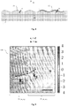
- the Figure 5 represents the behavior, seen from above, of a hydro-elastic wave filmed in the laboratory and propagating on a composite structure 100 as defined above.
- the gray scale on the side of the graph represents the height of the wave / wave relative to the average position of the surface of the liquid at rest which is 0.
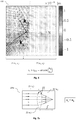
- FIGS. 7a and 7b show two particular embodiments of the invention making it possible to produce a converging lens capable of focusing the energy of the hydroelastic waves propagating on the composite structure at a point.
- the composite structure 200a shown in Figure 7a is made up of three contiguous zones Z1, Z2 and Z3. Zones Z1 and Z3 have the same index n 1 , as defined above (ie n i is proportional to the inverse of the propagation speed Vi in zone Zi). The index n 2 of zone Z2 is for its part different from n 1 , such that n 1 ⁇ n 2 .
- Zone Z2 has the shape of a biconvex lens of radius of curvature R. That is to say that the interface between zones Z1 and Z2 is an arc of circle of radius R whose curvature is turned on the side of the zone Z1, through which the waves arrive, and the interface in the zones Z2 and Z3 is also an arc of a circle of radius R, the curvature of which is turned towards the side of the zone Z3, through which the waves exit.
- the composite structure 200b illustrated in Figure 7b proposes another embodiment of a converging lens.
- the composite structure 200b is also composed of three contiguous zones Z1, Z2 and Z3. Zones Z1 and Z3 have the same index n 1 , and zone Z2 has index n 2 such that n 1 > n 2 .
- the zone Z2 has the shape of a biconcave lens of radius of curvature R. That is to say that the interface between the zones Z1 and Z2 is an arc of a circle of radius R whose curvature is turned towards the side of the zone Z2, and the interface in the zones Z2 and Z3 is also an arc of a circle of radius R, the curvature of which is also turned towards the side of the zone Z2.
- a surface hydro-elastic wave control system comprising one of the composite structures 200a and 200b as defined above can therefore be advantageously used to recover the energy of the hydro-elastic waves propagating on the surface of a liquid on which will be installed the control structure, the latter being adapted to focus the waves at a point, such as a converging lens.
- such a structure will make it possible to increase the performance of a device placed at the focal point of the composite structure 200a or 200b and capable of converting the energy of the hydro-elastic waves received into an electric power for example, such as devices used at sea that transform wave energy into electricity.
- the shape of the zones and interfaces is the same as that described previously except that when the zone Z2 has a biconvex shape, the index n 1 must be greater than n 2 and when the zone Z2 has a biconcave form, index n 1 must be less than n 2 .
- the Figure 8 represents another particular embodiment of the invention.
- the composite structure 300 is comparable to a wave reflector and uses the principle of the limit angle of refraction i lim defined above.
- the interface between the zones Z1 and Z2 is a right angle whose vertex is directed towards the side of the zone Z2 so that a hydro-elastic wave arriving on the zone Z1 is reflected, twice as for a light beam, in contact with the interface between zones Z1 and Z2 and starts again along an axis parallel to its direction of incidence, as is the case for a “cube corner” or optical reflector.
- a surface hydroelastic wave control system comprising a composite structure 300 as defined above can be advantageously used to protect a device having a part in contact with the surface of the liquid, such as a nuclear power plant, the composite structure 300 being suitable to protect the part in contact with the surface of the liquid and to reflect the hydro-elastic waves arriving on the device.
- the Figure 9 represents an embodiment of such an effective zone Zeff_i.
- the composite structure is then adapted for, when the control system is placed on the surface of the liquid such that a hydroelastic surface wave propagates on the first zone Z1 or Zeff_1 then on the second zone Z2 or Zeff_2 of the composite structure floating on the surface of the liquid of density p, and when the wavelength ⁇ i of the hydroelastic wave propagating in the zone Zi, respectively the effective wavelength ⁇ eff_i of the wave is propagating in the effective zone Zeff_i, respects the following equations (E6bis) and (E7bis), respectively the following equations (E16) and (E17): and 2 ⁇ ⁇ eff _ i ⁇ ⁇ ⁇ g D eff _ i 4 2 ⁇ ⁇ eff _ i ⁇ T eff _ i D eff _ i where g corresponds to the universal constant of gravitation and i corresponds to the index of the zone Zi or Zeff_i on which the hydroelastic wave propagates.
- n eff_i an effective index n eff_i from the effective velocity Veff_i of propagation of the hydroelastic waves in the effective zone Zeff_i, it is thus possible to create, by adjusting the bending coefficients Di or Deff_i and / or the shapes of said zones Zi or Zeff_i, components respecting the laws of geometrical optics such as a Fresnel lens or a corner of a cube / reflector which can be used to focus or reflect the hydro-elastic waves on a large surface of liquid while reducing the material necessary for the manufacture of an equivalent control system.
- geometrical optics such as a Fresnel lens or a corner of a cube / reflector which can be used to focus or reflect the hydro-elastic waves on a large surface of liquid while reducing the material necessary for the manufacture of an equivalent control system.
- the materials used for the production of the control systems and devices described above can be biodegradable materials so as not to pollute the liquid on which they are installed, and also allowing use over a certain period of time without the need for physical removal of the latter and therefore eliminating the costs of uninstalling.
Landscapes
- Engineering & Computer Science (AREA)
- General Engineering & Computer Science (AREA)
- Mechanical Engineering (AREA)
- Civil Engineering (AREA)
- Structural Engineering (AREA)
- Environmental & Geological Engineering (AREA)
- Ocean & Marine Engineering (AREA)
- Mechanical Light Control Or Optical Switches (AREA)
- Revetment (AREA)
- Lenses (AREA)
- Other Liquid Machine Or Engine Such As Wave Power Use (AREA)
Claims (11)
- System zur Steuerung der hydroelastischen Wellen an der Oberfläche einer Flüssigkeit (1), das eine Verbundstruktur (10) umfasst, die mindestens zwei Zonen Z1 und Z2 mit jeweiligen Biegekoeffizienten D1 und D2, dadurch gekennzeichnet, dass die jeweiligen Biegekoeffizienten D1 und D2 definiert sind durch die Gleichung:

wobei die Verbundstruktur (10) dafür geeignet ist, wenn das Steuerungssystem so auf der Oberfläche der Flüssigkeit (1) liegt, dass sich eine hydroelastische Oberflächenwelle an der ersten Zone Z1 und anschließend an der zweiten Zone Z2 der auf der Oberfläche der Flüssigkeit (1) mit einer Dichte ρ schwimmenden Verbundstruktur (10) ausbreitet, und wenn die Wellenlänge λi der hydroelastischen Welle in der Zone Zi die folgenden Gleichungen erfüllt:
- System nach Anspruch 1, wobei die Zonen Z1 und Z2 aneinandergrenzen.
- System nach einem der Ansprüche 1 bis 2, dadurch gekennzeichnet, dass sich die Biegekoeffizienten D1 und D2 durch Unterschiede der Dicke ei der Zonen Z1 und Z2, und/oder durch Unterschiede der Elastizitätsmodule Ei und/oder der Poisson-Koeffizienten vi der Materialien, aus denen die Zonen Z1 und Z2 bestehen, unterscheiden.
- System nach Anspruch 3, wobei die Entwicklung des Biegekoeffizienten zwischen dem Durchlauf von der Zone Z1 mit dem Koeffizienten D1 bis zur Zone Z2 mit dem Koeffizienten D2 kontinuierlich ist.
- System nach einem der Ansprüche 1 bis 4, wobei, nachdem der Index ni der Zone Zi als zur Inversen der Ausbreitungsgeschwindigkeit Vi der hydroelastischen Wellen in der Zone Zi proportional definiert wurde, die Ausbreitungsgeschwindigkeit Vi definiert ist durch die Gleichung:

- System nach Anspruch 5, das weiter eine dritte Zone Z3 umfasst, und so, dass:- die Zonen Z1, Z2 und Z3 aneinandergrenzen;- die Zonen Z1 und Z3 den gleichen Index n1 besitzen, der sich vom Index n2 der Zone Z2 unterscheidet, wobei Z1 die Eintrittszone der hydroelastischen Wellen ist, und Z3 die Austrittszone; und- die Formen der Grenzflächen zwischen den Zonen Kreisbögen mit einem Radius R sind, sodass sich die Menge {Z1, Z2, Z3} wie eine optische Linse mit einer Brennweite f verhält, die durch die Gleichung:

- System nach Anspruch 6, wobei die von der Menge {Z1, Z2, Z3} gebildete Linse konvergierend ist, wenn:- die Menge eine Form einer bikonvexen Linse aufweist und n1<n2; oder wenn- die Menge eine Form einer bikonkaven Linse aufweist und n1>n2.
- System nach Anspruch 5, wobei die Zonen Z1 und Z2 mit jeweiligen Indizes n1 und n2, die die Gleichungen:

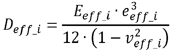
die Grenzfläche zwischen den Zonen ein rechter Winkel ist, dessen Spitze zur Seite der Zone Z2 gerichtet ist, sodass eine hydroelastische Welle, die an der Zone Z1 eintritt, bei Berührung der Grenzfläche zwischen den Zonen Z1 und Z2 zurückgeworfen wird und entlang einer zu ihrer Einfallsrichtung parallel Achse zurückläuft. - System nach einem der Ansprüche 1 bis 8, wobei mindestens eine der Zonen Zi aus einer Anordnung von Schwimmklötzen (30) besteht, die über elastische Verbindungsmittel (40) verbunden sind, sodass sich die Anordnung wie eine effektive Zone Zeff_i mit einem effektiven Biegekoeffizienten Deff_i, definiert durch die Gleichung:
wobei die Verbundstruktur dafür geeignet ist, wenn das Steuerungssystem so auf der Oberfläche der Flüssigkeit (1) liegt, dass sich eine hydroelastische Oberflächenwellen an der ersten Zone Z1 oder Zeff_1 und anschließend an der zweiten Zone Z2 oder Zeff_2 der auf der Oberfläche der Flüssigkeit (1) mit einer Dichte ρ schwimmenden Verbundstruktur ausbreitet, und wenn die Wellenlänge λi der sich in der Zone Zi ausbreitenden hydroelastischen Welle, beziehungsweise die effektive Wellenlänge λeff_i der sich in der effektiven Zone Zeff_i ausbreitenden Welle die folgenden Gleichungen erfüllt:

- Verwendung eines Systems zur Steuerung der hydroelastischen Oberflächenwellen nach Anspruch 7, um die Energie der sich an der Oberfläche einer Flüssigkeit ausbreitenden Wellen so einzufangen, dass die Verbundstruktur (200a oder 200b) des Systems zur Steuerung der Wellen dafür geeignet ist, die hydroelastischen Wellen an einem Punkt zu konzentrieren.
- Verwendung eines Systems zur Steuerung der hydroelastischen Oberflächenwellen nach Anspruch 8, um eine Vorrichtung zu schützen, die einen Teil besitzt, der sich mit der Oberfläche der Flüssigkeit in Berührung befindet, wobei die Verbundstruktur (300) des Systems dafür geeignet ist, den Teil zu schützen, der sich mit der Oberfläche der Flüssigkeit in Berührung befindet, und die an der Vorrichtung eintreffenden hydroelastischen Wellen zurückzuwerfen.
Applications Claiming Priority (2)
| Application Number | Priority Date | Filing Date | Title |
|---|---|---|---|
| FR1752718A FR3064652B1 (fr) | 2017-03-30 | 2017-03-30 | Dispositif de controle de l'energie des vagues |
| PCT/FR2018/050791 WO2018178590A1 (fr) | 2017-03-30 | 2018-03-29 | Dispositif de contrôle de l'énergie des vagues |
Publications (2)
| Publication Number | Publication Date |
|---|---|
| EP3601678A1 EP3601678A1 (de) | 2020-02-05 |
| EP3601678B1 true EP3601678B1 (de) | 2020-10-28 |
Family
ID=59070841
Family Applications (1)
| Application Number | Title | Priority Date | Filing Date |
|---|---|---|---|
| EP18722109.8A Not-in-force EP3601678B1 (de) | 2017-03-30 | 2018-03-29 | Vorrichtung zur wellenenergiesteuerung |
Country Status (7)
| Country | Link |
|---|---|
| US (1) | US10640939B2 (de) |
| EP (1) | EP3601678B1 (de) |
| JP (1) | JP2020516802A (de) |
| CN (1) | CN110753770A (de) |
| AU (1) | AU2018242374A1 (de) |
| FR (1) | FR3064652B1 (de) |
| WO (1) | WO2018178590A1 (de) |
Families Citing this family (1)
| Publication number | Priority date | Publication date | Assignee | Title |
|---|---|---|---|---|
| FR3064652B1 (fr) | 2017-03-30 | 2019-05-03 | Centre National De La Recherche Scientifique | Dispositif de controle de l'energie des vagues |
Family Cites Families (14)
| Publication number | Priority date | Publication date | Assignee | Title |
|---|---|---|---|---|
| US3188813A (en) * | 1961-03-23 | 1965-06-15 | Us Rubber Co | Article and process for wave damping |
| NO140237C (no) * | 1977-09-13 | 1979-07-25 | Sentralinst For Ind Forskning | Anlegg for konsentrering av vannboelger |
| ATE12675T1 (de) * | 1982-03-15 | 1985-04-15 | Horst Quarz | Wellenkraftmaschine. |
| US4836709A (en) * | 1987-06-15 | 1989-06-06 | Canadian Patents And Development Limited | Water wave absorber |
| JPH02266011A (ja) * | 1989-04-03 | 1990-10-30 | Tokyu Constr Co Ltd | 消波方法及び消波構造物 |
| SE0601581L (sv) * | 2006-07-17 | 2008-01-18 | Ulf Erlingsson | Vågdämpare för vattenvågor |
| US8679331B2 (en) * | 2008-01-03 | 2014-03-25 | The Invention Science Fund I Llc | Water alteration structure movement method and system |
| ES2819219T3 (es) * | 2008-11-25 | 2021-04-15 | Thomas J Lochtefeld | Método y aparato para amortiguar olas en una piscina de olas |
| US9222457B2 (en) | 2013-03-12 | 2015-12-29 | Raytheon Company | Wave energy concentration using water wave band gap structure with defect cavities |
| TWI521135B (zh) | 2013-04-08 | 2016-02-11 | 國立台灣大學 | 波浪能聚集與增益裝置 |
| CN104233994A (zh) * | 2013-06-22 | 2014-12-24 | 王化国 | 一种利用挡板阻碍海啸的方法 |
| CA3011893A1 (en) * | 2016-01-18 | 2017-07-27 | Horacio VELASCO | Method for operation of hydropower reservoir with a 2-parameter elevation rule curve |
| FR3064652B1 (fr) | 2017-03-30 | 2019-05-03 | Centre National De La Recherche Scientifique | Dispositif de controle de l'energie des vagues |
| US10550534B1 (en) * | 2019-07-31 | 2020-02-04 | Kuwait Institute For Scientific Research | Method for damping ocean waves in a coastal area |
-
2017
- 2017-03-30 FR FR1752718A patent/FR3064652B1/fr not_active Expired - Fee Related
-
2018
- 2018-03-29 WO PCT/FR2018/050791 patent/WO2018178590A1/fr not_active Ceased
- 2018-03-29 CN CN201880022096.8A patent/CN110753770A/zh active Pending
- 2018-03-29 US US16/497,720 patent/US10640939B2/en not_active Expired - Fee Related
- 2018-03-29 EP EP18722109.8A patent/EP3601678B1/de not_active Not-in-force
- 2018-03-29 AU AU2018242374A patent/AU2018242374A1/en not_active Abandoned
- 2018-03-29 JP JP2019553878A patent/JP2020516802A/ja active Pending
Non-Patent Citations (1)
| Title |
|---|
| None * |
Also Published As
| Publication number | Publication date |
|---|---|
| FR3064652A1 (fr) | 2018-10-05 |
| EP3601678A1 (de) | 2020-02-05 |
| US10640939B2 (en) | 2020-05-05 |
| CN110753770A (zh) | 2020-02-04 |
| FR3064652B1 (fr) | 2019-05-03 |
| WO2018178590A1 (fr) | 2018-10-04 |
| JP2020516802A (ja) | 2020-06-11 |
| AU2018242374A1 (en) | 2019-10-31 |
| US20200032470A1 (en) | 2020-01-30 |
Similar Documents
| Publication | Publication Date | Title |
|---|---|---|
| FR3046851B1 (fr) | Guide optique ameliore et systeme optique | |
| EP3526065B1 (de) | Windschutzscheibe für fahrhilfe | |
| FR3071626A1 (fr) | Dispositif de couplage optique pour un circuit photonique. | |
| EP3063468A1 (de) | Optischer leiter zur erzeugung leuchtender prägungen | |
| WO2001071420A1 (fr) | Dispositif de visee a quatre surfaces reflechissantes fixes | |
| EP2277074A1 (de) | Informative brille | |
| EP3526064A1 (de) | Windschutzscheibe und vorrichtung zur fahrassistenz | |
| EP3601678B1 (de) | Vorrichtung zur wellenenergiesteuerung | |
| EP3513230B1 (de) | Optische kupplungsvorrichtung | |
| EP3938836A2 (de) | Polarisationsseparationsvorrichtung, differenzinterferometer und optisches differenzkontrastmikroskop mit einer solchen vorrichtung | |
| CA2555806C (fr) | Miroir bimorphe avec deux couches piezo-electriques separees par une ame centrale en materiau semi-rigide | |
| FR2950672A1 (fr) | Module optique avec plieuse formee par un dioptre materiau transparent / air | |
| EP3093634B1 (de) | Optischer detektor mit gekrümmter detektionsfläche | |
| EP2354832A1 (de) | Bimorphes optisches Element | |
| EP2473824B1 (de) | Feldkompensiertes interferometer | |
| EP4075182A1 (de) | Optischer scanner | |
| FR2641621A1 (fr) | Systeme optique destine a etre utilise avec un viseur d'appareil photographique reflex a un seul objectif | |
| EP3933483A1 (de) | Optischer scanner | |
| WO2020084264A1 (fr) | Composant optique a filtre | |
| EP4320473B1 (de) | Katadioptrisches doppelfeldteleskop | |
| EP0214045B1 (de) | Optisches Gerät mit selektivem Spektralfilter | |
| WO2026013271A1 (fr) | Dispositif et procédé de nettoyage d'un support par conversion d'une onde de volume ultrasonore en une onde de surface ultrasonore | |
| WO2025027191A1 (fr) | Dispositif lumineux pour projeter une image sur une surface de projection située à l'intérieur d'un habitacle de véhicule automobile | |
| FR2741449A1 (fr) | Detecteur d'un rayonnement diffuse | |
| WO2022219272A1 (fr) | Dispositif réflecteur destiné à émettre une pluralité de faisceaux réfléchis à partir d'un unique faisceau lumineux principal |
Legal Events
| Date | Code | Title | Description |
|---|---|---|---|
| STAA | Information on the status of an ep patent application or granted ep patent |
Free format text: STATUS: UNKNOWN |
|
| STAA | Information on the status of an ep patent application or granted ep patent |
Free format text: STATUS: THE INTERNATIONAL PUBLICATION HAS BEEN MADE |
|
| PUAI | Public reference made under article 153(3) epc to a published international application that has entered the european phase |
Free format text: ORIGINAL CODE: 0009012 |
|
| STAA | Information on the status of an ep patent application or granted ep patent |
Free format text: STATUS: REQUEST FOR EXAMINATION WAS MADE |
|
| 17P | Request for examination filed |
Effective date: 20191028 |
|
| AK | Designated contracting states |
Kind code of ref document: A1 Designated state(s): AL AT BE BG CH CY CZ DE DK EE ES FI FR GB GR HR HU IE IS IT LI LT LU LV MC MK MT NL NO PL PT RO RS SE SI SK SM TR |
|
| AX | Request for extension of the european patent |
Extension state: BA ME |
|
| DAV | Request for validation of the european patent (deleted) | ||
| DAX | Request for extension of the european patent (deleted) | ||
| GRAP | Despatch of communication of intention to grant a patent |
Free format text: ORIGINAL CODE: EPIDOSNIGR1 |
|
| STAA | Information on the status of an ep patent application or granted ep patent |
Free format text: STATUS: GRANT OF PATENT IS INTENDED |
|
| GRAS | Grant fee paid |
Free format text: ORIGINAL CODE: EPIDOSNIGR3 |
|
| INTG | Intention to grant announced |
Effective date: 20200827 |
|
| GRAA | (expected) grant |
Free format text: ORIGINAL CODE: 0009210 |
|
| STAA | Information on the status of an ep patent application or granted ep patent |
Free format text: STATUS: THE PATENT HAS BEEN GRANTED |
|
| AK | Designated contracting states |
Kind code of ref document: B1 Designated state(s): AL AT BE BG CH CY CZ DE DK EE ES FI FR GB GR HR HU IE IS IT LI LT LU LV MC MK MT NL NO PL PT RO RS SE SI SK SM TR |
|
| REG | Reference to a national code |
Ref country code: GB Ref legal event code: FG4D Free format text: NOT ENGLISH |
|
| REG | Reference to a national code |
Ref country code: CH Ref legal event code: EP |
|
| REG | Reference to a national code |
Ref country code: DE Ref legal event code: R096 Ref document number: 602018009180 Country of ref document: DE |
|
| REG | Reference to a national code |
Ref country code: AT Ref legal event code: REF Ref document number: 1328359 Country of ref document: AT Kind code of ref document: T Effective date: 20201115 |
|
| REG | Reference to a national code |
Ref country code: IE Ref legal event code: FG4D Free format text: LANGUAGE OF EP DOCUMENT: FRENCH |
|
| REG | Reference to a national code |
Ref country code: AT Ref legal event code: MK05 Ref document number: 1328359 Country of ref document: AT Kind code of ref document: T Effective date: 20201028 |
|
| REG | Reference to a national code |
Ref country code: NL Ref legal event code: MP Effective date: 20201028 |
|
| PG25 | Lapsed in a contracting state [announced via postgrant information from national office to epo] |
Ref country code: GR Free format text: LAPSE BECAUSE OF FAILURE TO SUBMIT A TRANSLATION OF THE DESCRIPTION OR TO PAY THE FEE WITHIN THE PRESCRIBED TIME-LIMIT Effective date: 20210129 Ref country code: NO Free format text: LAPSE BECAUSE OF FAILURE TO SUBMIT A TRANSLATION OF THE DESCRIPTION OR TO PAY THE FEE WITHIN THE PRESCRIBED TIME-LIMIT Effective date: 20210128 Ref country code: FI Free format text: LAPSE BECAUSE OF FAILURE TO SUBMIT A TRANSLATION OF THE DESCRIPTION OR TO PAY THE FEE WITHIN THE PRESCRIBED TIME-LIMIT Effective date: 20201028 Ref country code: RS Free format text: LAPSE BECAUSE OF FAILURE TO SUBMIT A TRANSLATION OF THE DESCRIPTION OR TO PAY THE FEE WITHIN THE PRESCRIBED TIME-LIMIT Effective date: 20201028 Ref country code: PT Free format text: LAPSE BECAUSE OF FAILURE TO SUBMIT A TRANSLATION OF THE DESCRIPTION OR TO PAY THE FEE WITHIN THE PRESCRIBED TIME-LIMIT Effective date: 20210301 |
|
| REG | Reference to a national code |
Ref country code: LT Ref legal event code: MG4D |
|
| PG25 | Lapsed in a contracting state [announced via postgrant information from national office to epo] |
Ref country code: SE Free format text: LAPSE BECAUSE OF FAILURE TO SUBMIT A TRANSLATION OF THE DESCRIPTION OR TO PAY THE FEE WITHIN THE PRESCRIBED TIME-LIMIT Effective date: 20201028 Ref country code: PL Free format text: LAPSE BECAUSE OF FAILURE TO SUBMIT A TRANSLATION OF THE DESCRIPTION OR TO PAY THE FEE WITHIN THE PRESCRIBED TIME-LIMIT Effective date: 20201028 Ref country code: IS Free format text: LAPSE BECAUSE OF FAILURE TO SUBMIT A TRANSLATION OF THE DESCRIPTION OR TO PAY THE FEE WITHIN THE PRESCRIBED TIME-LIMIT Effective date: 20210228 Ref country code: LV Free format text: LAPSE BECAUSE OF FAILURE TO SUBMIT A TRANSLATION OF THE DESCRIPTION OR TO PAY THE FEE WITHIN THE PRESCRIBED TIME-LIMIT Effective date: 20201028 Ref country code: BG Free format text: LAPSE BECAUSE OF FAILURE TO SUBMIT A TRANSLATION OF THE DESCRIPTION OR TO PAY THE FEE WITHIN THE PRESCRIBED TIME-LIMIT Effective date: 20210128 Ref country code: AT Free format text: LAPSE BECAUSE OF FAILURE TO SUBMIT A TRANSLATION OF THE DESCRIPTION OR TO PAY THE FEE WITHIN THE PRESCRIBED TIME-LIMIT Effective date: 20201028 Ref country code: ES Free format text: LAPSE BECAUSE OF FAILURE TO SUBMIT A TRANSLATION OF THE DESCRIPTION OR TO PAY THE FEE WITHIN THE PRESCRIBED TIME-LIMIT Effective date: 20201028 |
|
| PG25 | Lapsed in a contracting state [announced via postgrant information from national office to epo] |
Ref country code: NL Free format text: LAPSE BECAUSE OF FAILURE TO SUBMIT A TRANSLATION OF THE DESCRIPTION OR TO PAY THE FEE WITHIN THE PRESCRIBED TIME-LIMIT Effective date: 20201028 Ref country code: HR Free format text: LAPSE BECAUSE OF FAILURE TO SUBMIT A TRANSLATION OF THE DESCRIPTION OR TO PAY THE FEE WITHIN THE PRESCRIBED TIME-LIMIT Effective date: 20201028 |
|
| REG | Reference to a national code |
Ref country code: DE Ref legal event code: R097 Ref document number: 602018009180 Country of ref document: DE |
|
| PG25 | Lapsed in a contracting state [announced via postgrant information from national office to epo] |
Ref country code: RO Free format text: LAPSE BECAUSE OF FAILURE TO SUBMIT A TRANSLATION OF THE DESCRIPTION OR TO PAY THE FEE WITHIN THE PRESCRIBED TIME-LIMIT Effective date: 20201028 Ref country code: LT Free format text: LAPSE BECAUSE OF FAILURE TO SUBMIT A TRANSLATION OF THE DESCRIPTION OR TO PAY THE FEE WITHIN THE PRESCRIBED TIME-LIMIT Effective date: 20201028 Ref country code: EE Free format text: LAPSE BECAUSE OF FAILURE TO SUBMIT A TRANSLATION OF THE DESCRIPTION OR TO PAY THE FEE WITHIN THE PRESCRIBED TIME-LIMIT Effective date: 20201028 Ref country code: CZ Free format text: LAPSE BECAUSE OF FAILURE TO SUBMIT A TRANSLATION OF THE DESCRIPTION OR TO PAY THE FEE WITHIN THE PRESCRIBED TIME-LIMIT Effective date: 20201028 Ref country code: SK Free format text: LAPSE BECAUSE OF FAILURE TO SUBMIT A TRANSLATION OF THE DESCRIPTION OR TO PAY THE FEE WITHIN THE PRESCRIBED TIME-LIMIT Effective date: 20201028 Ref country code: SM Free format text: LAPSE BECAUSE OF FAILURE TO SUBMIT A TRANSLATION OF THE DESCRIPTION OR TO PAY THE FEE WITHIN THE PRESCRIBED TIME-LIMIT Effective date: 20201028 |
|
| PG25 | Lapsed in a contracting state [announced via postgrant information from national office to epo] |
Ref country code: DK Free format text: LAPSE BECAUSE OF FAILURE TO SUBMIT A TRANSLATION OF THE DESCRIPTION OR TO PAY THE FEE WITHIN THE PRESCRIBED TIME-LIMIT Effective date: 20201028 |
|
| PLBE | No opposition filed within time limit |
Free format text: ORIGINAL CODE: 0009261 |
|
| STAA | Information on the status of an ep patent application or granted ep patent |
Free format text: STATUS: NO OPPOSITION FILED WITHIN TIME LIMIT |
|
| REG | Reference to a national code |
Ref country code: DE Ref legal event code: R119 Ref document number: 602018009180 Country of ref document: DE |
|
| 26N | No opposition filed |
Effective date: 20210729 |
|
| PG25 | Lapsed in a contracting state [announced via postgrant information from national office to epo] |
Ref country code: AL Free format text: LAPSE BECAUSE OF FAILURE TO SUBMIT A TRANSLATION OF THE DESCRIPTION OR TO PAY THE FEE WITHIN THE PRESCRIBED TIME-LIMIT Effective date: 20201028 Ref country code: IT Free format text: LAPSE BECAUSE OF FAILURE TO SUBMIT A TRANSLATION OF THE DESCRIPTION OR TO PAY THE FEE WITHIN THE PRESCRIBED TIME-LIMIT Effective date: 20201028 Ref country code: MC Free format text: LAPSE BECAUSE OF FAILURE TO SUBMIT A TRANSLATION OF THE DESCRIPTION OR TO PAY THE FEE WITHIN THE PRESCRIBED TIME-LIMIT Effective date: 20201028 |
|
| REG | Reference to a national code |
Ref country code: CH Ref legal event code: PL |
|
| PG25 | Lapsed in a contracting state [announced via postgrant information from national office to epo] |
Ref country code: SI Free format text: LAPSE BECAUSE OF FAILURE TO SUBMIT A TRANSLATION OF THE DESCRIPTION OR TO PAY THE FEE WITHIN THE PRESCRIBED TIME-LIMIT Effective date: 20201028 |
|
| REG | Reference to a national code |
Ref country code: BE Ref legal event code: MM Effective date: 20210331 |
|
| PG25 | Lapsed in a contracting state [announced via postgrant information from national office to epo] |
Ref country code: CH Free format text: LAPSE BECAUSE OF NON-PAYMENT OF DUE FEES Effective date: 20210331 Ref country code: DE Free format text: LAPSE BECAUSE OF NON-PAYMENT OF DUE FEES Effective date: 20211001 Ref country code: LU Free format text: LAPSE BECAUSE OF NON-PAYMENT OF DUE FEES Effective date: 20210329 Ref country code: IE Free format text: LAPSE BECAUSE OF NON-PAYMENT OF DUE FEES Effective date: 20210329 Ref country code: LI Free format text: LAPSE BECAUSE OF NON-PAYMENT OF DUE FEES Effective date: 20210331 Ref country code: FR Free format text: LAPSE BECAUSE OF NON-PAYMENT OF DUE FEES Effective date: 20210331 |
|
| PG25 | Lapsed in a contracting state [announced via postgrant information from national office to epo] |
Ref country code: IS Free format text: LAPSE BECAUSE OF FAILURE TO SUBMIT A TRANSLATION OF THE DESCRIPTION OR TO PAY THE FEE WITHIN THE PRESCRIBED TIME-LIMIT Effective date: 20210228 |
|
| PG25 | Lapsed in a contracting state [announced via postgrant information from national office to epo] |
Ref country code: BE Free format text: LAPSE BECAUSE OF NON-PAYMENT OF DUE FEES Effective date: 20210331 |
|
| GBPC | Gb: european patent ceased through non-payment of renewal fee |
Effective date: 20220329 |
|
| PG25 | Lapsed in a contracting state [announced via postgrant information from national office to epo] |
Ref country code: GB Free format text: LAPSE BECAUSE OF NON-PAYMENT OF DUE FEES Effective date: 20220329 |
|
| PG25 | Lapsed in a contracting state [announced via postgrant information from national office to epo] |
Ref country code: CY Free format text: LAPSE BECAUSE OF FAILURE TO SUBMIT A TRANSLATION OF THE DESCRIPTION OR TO PAY THE FEE WITHIN THE PRESCRIBED TIME-LIMIT Effective date: 20201028 |
|
| PG25 | Lapsed in a contracting state [announced via postgrant information from national office to epo] |
Ref country code: HU Free format text: LAPSE BECAUSE OF FAILURE TO SUBMIT A TRANSLATION OF THE DESCRIPTION OR TO PAY THE FEE WITHIN THE PRESCRIBED TIME-LIMIT; INVALID AB INITIO Effective date: 20180329 |
|
| PG25 | Lapsed in a contracting state [announced via postgrant information from national office to epo] |
Ref country code: MK Free format text: LAPSE BECAUSE OF FAILURE TO SUBMIT A TRANSLATION OF THE DESCRIPTION OR TO PAY THE FEE WITHIN THE PRESCRIBED TIME-LIMIT Effective date: 20201028 |
|
| PG25 | Lapsed in a contracting state [announced via postgrant information from national office to epo] |
Ref country code: TR Free format text: LAPSE BECAUSE OF FAILURE TO SUBMIT A TRANSLATION OF THE DESCRIPTION OR TO PAY THE FEE WITHIN THE PRESCRIBED TIME-LIMIT Effective date: 20201028 |
|
| PG25 | Lapsed in a contracting state [announced via postgrant information from national office to epo] |
Ref country code: MT Free format text: LAPSE BECAUSE OF FAILURE TO SUBMIT A TRANSLATION OF THE DESCRIPTION OR TO PAY THE FEE WITHIN THE PRESCRIBED TIME-LIMIT Effective date: 20201028 |