EP3403153B1 - Überwachungssystem für erdungsvorrichtung - Google Patents
Überwachungssystem für erdungsvorrichtung Download PDFInfo
- Publication number
- EP3403153B1 EP3403153B1 EP17704563.0A EP17704563A EP3403153B1 EP 3403153 B1 EP3403153 B1 EP 3403153B1 EP 17704563 A EP17704563 A EP 17704563A EP 3403153 B1 EP3403153 B1 EP 3403153B1
- Authority
- EP
- European Patent Office
- Prior art keywords
- data
- electrical
- sensor
- processor
- grounding
- Prior art date
- Legal status (The legal status is an assumption and is not a legal conclusion. Google has not performed a legal analysis and makes no representation as to the accuracy of the status listed.)
- Not-in-force
Links
- 238000012544 monitoring process Methods 0.000 title claims description 77
- 238000005070 sampling Methods 0.000 claims description 179
- 230000002547 anomalous effect Effects 0.000 claims description 41
- 230000015654 memory Effects 0.000 claims description 27
- 238000000034 method Methods 0.000 claims description 12
- 230000005611 electricity Effects 0.000 claims description 8
- 230000008859 change Effects 0.000 description 6
- 238000004891 communication Methods 0.000 description 5
- 239000004020 conductor Substances 0.000 description 4
- 230000006870 function Effects 0.000 description 4
- 230000037361 pathway Effects 0.000 description 4
- 230000000712 assembly Effects 0.000 description 3
- 238000000429 assembly Methods 0.000 description 3
- 239000000463 material Substances 0.000 description 3
- 238000012545 processing Methods 0.000 description 3
- 230000006403 short-term memory Effects 0.000 description 3
- 238000012546 transfer Methods 0.000 description 3
- RYGMFSIKBFXOCR-UHFFFAOYSA-N Copper Chemical compound [Cu] RYGMFSIKBFXOCR-UHFFFAOYSA-N 0.000 description 2
- 229910000881 Cu alloy Inorganic materials 0.000 description 2
- 230000005355 Hall effect Effects 0.000 description 2
- 229910052802 copper Inorganic materials 0.000 description 2
- 239000010949 copper Substances 0.000 description 2
- 238000010586 diagram Methods 0.000 description 2
- 230000007246 mechanism Effects 0.000 description 2
- 230000002093 peripheral effect Effects 0.000 description 2
- 230000003068 static effect Effects 0.000 description 2
- 230000002411 adverse Effects 0.000 description 1
- 230000003139 buffering effect Effects 0.000 description 1
- 238000004140 cleaning Methods 0.000 description 1
- 125000004122 cyclic group Chemical group 0.000 description 1
- 230000007547 defect Effects 0.000 description 1
- 230000000694 effects Effects 0.000 description 1
- 230000005684 electric field Effects 0.000 description 1
- 230000003628 erosive effect Effects 0.000 description 1
- 238000011156 evaluation Methods 0.000 description 1
- 230000005284 excitation Effects 0.000 description 1
- 230000004907 flux Effects 0.000 description 1
- 230000036541 health Effects 0.000 description 1
- 238000002347 injection Methods 0.000 description 1
- 239000007924 injection Substances 0.000 description 1
- 238000011835 investigation Methods 0.000 description 1
- 239000002184 metal Substances 0.000 description 1
- 229910052751 metal Inorganic materials 0.000 description 1
- 230000000737 periodic effect Effects 0.000 description 1
- 230000004044 response Effects 0.000 description 1
- 230000001052 transient effect Effects 0.000 description 1
Images


Classifications
-
- G—PHYSICS
- G01—MEASURING; TESTING
- G01R—MEASURING ELECTRIC VARIABLES; MEASURING MAGNETIC VARIABLES
- G01R19/00—Arrangements for measuring currents or voltages or for indicating presence or sign thereof
- G01R19/25—Arrangements for measuring currents or voltages or for indicating presence or sign thereof using digital measurement techniques
- G01R19/2506—Arrangements for conditioning or analysing measured signals, e.g. for indicating peak values ; Details concerning sampling, digitizing or waveform capturing
- G01R19/2509—Details concerning sampling, digitizing or waveform capturing
-
- G—PHYSICS
- G01—MEASURING; TESTING
- G01R—MEASURING ELECTRIC VARIABLES; MEASURING MAGNETIC VARIABLES
- G01R19/00—Arrangements for measuring currents or voltages or for indicating presence or sign thereof
- G01R19/25—Arrangements for measuring currents or voltages or for indicating presence or sign thereof using digital measurement techniques
-
- G—PHYSICS
- G01—MEASURING; TESTING
- G01R—MEASURING ELECTRIC VARIABLES; MEASURING MAGNETIC VARIABLES
- G01R31/00—Arrangements for testing electric properties; Arrangements for locating electric faults; Arrangements for electrical testing characterised by what is being tested not provided for elsewhere
- G01R31/34—Testing dynamo-electric machines
- G01R31/343—Testing dynamo-electric machines in operation
-
- G—PHYSICS
- G05—CONTROLLING; REGULATING
- G05B—CONTROL OR REGULATING SYSTEMS IN GENERAL; FUNCTIONAL ELEMENTS OF SUCH SYSTEMS; MONITORING OR TESTING ARRANGEMENTS FOR SUCH SYSTEMS OR ELEMENTS
- G05B23/00—Testing or monitoring of control systems or parts thereof
- G05B23/02—Electric testing or monitoring
- G05B23/0205—Electric testing or monitoring by means of a monitoring system capable of detecting and responding to faults
- G05B23/0218—Electric testing or monitoring by means of a monitoring system capable of detecting and responding to faults characterised by the fault detection method dealing with either existing or incipient faults
- G05B23/0224—Process history based detection method, e.g. whereby history implies the availability of large amounts of data
- G05B23/0227—Qualitative history assessment, whereby the type of data acted upon, e.g. waveforms, images or patterns, is not relevant, e.g. rule based assessment; if-then decisions
- G05B23/0235—Qualitative history assessment, whereby the type of data acted upon, e.g. waveforms, images or patterns, is not relevant, e.g. rule based assessment; if-then decisions based on a comparison with predetermined threshold or range, e.g. "classical methods", carried out during normal operation; threshold adaptation or choice; when or how to compare with the threshold
-
- H—ELECTRICITY
- H02—GENERATION; CONVERSION OR DISTRIBUTION OF ELECTRIC POWER
- H02K—DYNAMO-ELECTRIC MACHINES
- H02K11/00—Structural association of dynamo-electric machines with electric components or with devices for shielding, monitoring or protection
- H02K11/40—Structural association with grounding devices
-
- G—PHYSICS
- G01—MEASURING; TESTING
- G01R—MEASURING ELECTRIC VARIABLES; MEASURING MAGNETIC VARIABLES
- G01R31/00—Arrangements for testing electric properties; Arrangements for locating electric faults; Arrangements for electrical testing characterised by what is being tested not provided for elsewhere
- G01R31/50—Testing of electric apparatus, lines, cables or components for short-circuits, continuity, leakage current or incorrect line connections
- G01R31/52—Testing for short-circuits, leakage current or ground faults
Definitions
- the disclosure generally relates to monitoring systems for monitoring one or more components of a device having a rotating shaft susceptible to having a stray electrical voltage on the shaft. More specifically, the disclosure relates to monitoring apparatus, assemblies, systems and methods of monitoring one or more components, such as a grounding apparatus, of a device having a rotating shaft having a stray electrical voltage on the shaft.
- stray voltage may build up on the rotating shaft.
- all rotating shafts inherently generate electric fields from asymmetries in magnetic field distribution between rotor and stator, residual magnetic flux in the shaft, excitation and electrostatic charges.
- These stray voltages may ultimately exit the rotating shaft through structures such as the bearings supporting the rotating shaft. Over time, this can damage the bearings and/or other components of the device.
- a grounding apparatus may be used to ground the rotating shaft.
- Such grounding apparatus may include grounding brushes, grounding straps, grounding ropes and other grounding members configured to ground the rotating shaft of the device.
- propulsion shafts may include a grounding apparatus in order to avoid galvanic activity that can otherwise cause erosion.
- WO 00/69062 discloses a rotating machinery monitor that provides a warning that is indicative of a developing problem with the rotating machinery.
- the rotating machinery monitor has at least one current sensor for detecting shaft grounding current in the rotating machinery, at least one voltage sensor for detecting shaft voltage in the rotating machinery, a change detector for determining rate of change in the shaft grounding current and a change detector for determining rate of change in the shaft voltage, and an evaluation system for producing a warning as a function of the change in the shaft grounding current, the rate of change in the shaft voltage, the shaft grounding current and the shaft voltage.
- WO 2007/021425 discloses a method and monitoring system for tracking operational parameters of a drive train of a monitored system including a sensor unit affixed to the drive train.
- the sensor unit includes a sensor for generating an analog signal in response to an operating condition of the monitored system and an integrated local processor for processing the analog signal generated by the sensor.
- the disclosure is directed to designs, materials and methods of monitoring the performance of a grounding apparatus for an electric generator, an electric motor, a gearbox, a compressor, a pump, a drive shaft, an axle, or other device including a rotating shaft subject to stray electrical voltage on the shaft.
- the electrical sensor comprises an electrical current sensor.
- the electrical sensor comprises an electrical voltage sensor.
- the electrical sensor detects the electrical parameter at a sampling rate that provides enough data points per second to capture any anomalous or threshold condition that may be occurring in the device.
- the sampling period is equal to or greater than one complete revolution of the rotating shaft.
- the processor is further configured to not analyze the data representing the electrical parameter for a period of time immediately after the sampling period.
- the period of time immediately after the sampling period is longer than the sampling period.
- the processor is configured to analyze the data representing the electrical parameter from the electrical sensor for a sampling period ranging from 0.01 seconds per each second to 0.5 seconds per each second, and the processor is configured to not analyze the data representing the electrical parameter from the electrical sensor for a subsequent time period ranging from 0.5 seconds per each second to 0.99 seconds per each second.
- the processor is configured to analyze the data representing the electrical parameter from the electrical sensor for a sampling period ranging from 0.05 seconds per each second to 0.25 seconds per each second, and the processor is configured to not analyze the data representing the electrical parameter from the electrical sensor for a subsequent time period ranging from 0.75 seconds per each second to 0.95 seconds per each second.
- the processor is configured to analyze the data representing the electrical parameter from the electrical sensor for a sampling period of 0.1 seconds per each second, and the processor is configured to not analyze the data representing the electrical parameter from the electrical sensor for a subsequent time period of 0.9 seconds per each second.
- the shaft grounding and monitoring system includes a grounding member that is configured to slidingly contact the rotating shaft and make electrical contact with the rotating shaft, the grounding member configured to be connected to a source of ground.
- An isolated contact member is configured to slidingly contact the rotating shaft and is electrically isolated from ground.
- a current sensor is configured to be coupled with the grounding member in order to sense an electrical current flowing from the rotating shaft to ground through the grounding member and is configured to sample at a first sampling rate.
- a voltage sensor is configured to be coupled with the isolated contact member in order to sense an electrical voltage in the shaft and is configured to periodically sample at a second sampling rate.
- a processor is operably coupled with the current sensor and with the voltage sensor and is configured to receive data from the current sensor and the voltage sensor.
- the processor is configured to analyze data from the current sensor and from the voltage sensor.
- a memory is operably coupled with the processor and is configured to store current sensor data processed by the processor that is representative of data provided by the current sensor and voltage data processed by the processor that is representative of data provided by the voltage sensor.
- the second sampling rate is higher than the first sampling rate.
- the grounding member comprises a first grounding rope.
- the first grounding rope comprises a plurality of conductive wires secured together.
- the isolated contact member comprises a second grounding rope that is not electrically connected to ground
- the first sampling rate is about 100,000 kHz or greater.
- the voltage sensor is configured to sample for only a portion of each second.
- the portion of each second is about one-tenth of each second.
- the second sampling rate is about 20MHz or more when sampling.
- the second sampling rate is about 40 MHz or more when sampling.
- the processor is further configured to analyze a snapshot of data from the current sensor during a sampling period in order to identify a potential anomalous or threshold condition.
- the processor if the processor does not identify a potential anomalous or threshold condition from the snapshot of data from the current sensor, the processor is further configured to store one or more values representative of the snapshot of data from the current sensor to memory.
- the processor if the processor does identify a potential anomalous or threshold condition from the snapshot of data from the current sensor, the processor is further configured to store one or more values representative of the snapshot of data from the current sensor to memory and to analyze a snapshot of data from the voltage sensor in order to provide additional information regarding the potential anomalous or threshold condition, the snapshot of data from the voltage sensor at least partially temporally aligned with the snapshot of data from the current sensor.
- the current sensor comprises a Hall effect sensor.
- the monitoring system includes a current sensor configured to sense an electrical current flowing through the grounding member and configured to sample at a first sampling rate for a first time interval.
- a voltage sensor is configured to sense an electrical voltage in the rotating shaft and is configured to periodically sample at a second sampling rate for a second time interval, wherein the second sampling rate is higher than the first sampling rate and the first time interval is longer than the second time interval and overlaps with the second time interval.
- a processor is operably coupled with the current sensor and with the voltage sensor and is configured to receive data from the current sensor and the voltage sensor. The processor is configured to analyze data indicative of electrical current sensed by the current sensor and data indicative of electrical voltage sensed by the voltage sensor.
- a memory is operably coupled with the processor and is configured to store information representative of the data from the current sensor and the data from the voltage sensor.
- the first sampling rate is about 100 kHz or greater.
- the voltage sensor is configured to sample for only a portion of each second.
- the portion of each second is about one-tenth of each second.
- the second sampling rate is about 20 MHz or more when sampling.
- the second sampling rate is about 40 MHz or more when sampling.
- the processor is further configured to analyze a snapshot of data from the current sensor during a sampling period in order to identify a potential anomalous or threshold condition.
- the processor if the processor does not identify a potential anomalous or threshold condition from the snapshot of data from the current sensor, the processor is further configured to store one or more values representative of the snapshot of data from the current sensor to memory.
- the processor if the processor does identify a potential anomalous or threshold condition from the snapshot of data from the current sensor, the processor is further configured to store one or more values representative of the snapshot of data from the current sensor to memory and to analyze a temporally aligned snapshot of data from the voltage sensor in order to provide additional information regarding the potential anomalous or threshold condition.
- the potential anomalous or threshold condition is indicated by a sensed electrical current value that exceeds a threshold.
- the potential anomalous or threshold condition is indicated by an external request for analysis.
- representative information pertaining to the snapshot of data from the current sensor comprises an average electrical current and/or a peak electrical current.
- the first sampling rate is about 100 kHz or more.
- data is periodically received from the voltage sensor for only a portion of each second.
- the portion of each second is about one-tenth of each second.
- the second sampling rate is about 20 MHz or more when sampling.
- the second sampling rate is about 40 MHz or more when sampling.
- the first sampling period is equal to or greater than one complete revolution of the rotating shaft.
- the second sampling period is less than the first sampling period.
- the second sampling period is about one-tenth of the first sampling period.
- the first sampling period overlaps the second sampling period.
- the second sampling period falls entirely within the first sampling period.
- the electrical sensor detects the electrical parameter at a sampling rate that provides enough data points per second to capture any anomalous or threshold condition that may be occurring in the device.
- the sampling period is equal to or greater than one complete revolution of the rotating shaft.
- the processor is further configured to not analyze the data representing the electrical parameter for a period of time immediately after the sampling period, the period of time being longer than the sampling period.
- the second electrical sensor is configured to be coupled with the conductive member.
- Another illustrative embodiment of the disclosure is a method of monitoring stray electricity in a rotating conductive shaft in a device.
- the method includes receiving data of a first electrical parameter at a first sampling rate during a first sampling period and periodically receiving data of a second electrical parameter at a second sampling rate during a second sampling period.
- the second sampling rate is higher than the first sampling rate.
- a snapshot of data of the first electrical parameter is analyzed to identify a potential anomalous or threshold condition. If a potential anomalous or threshold condition is seen in the snapshot of date of the first electrical parameter, analyzing a snapshot of data of the second electrical parameter is then analyzed.
- the snapshot of data of the second electrical parameter that is analyzed at least partially temporally aligns with the snapshot of data of the first electrical parameter that was analyzed.
- the first electrical parameter is an electrical current.
- the electrical current is sensed by an electrical current sensor or the electrical current is calculated based on measured voltage.
- the second electrical parameter is an electrical voltage
- the electrical voltage is sensed by an electrical voltage sensor or the electrical voltage is calculated based on measured current.
- the potential anomalous or threshold condition is indicated by a sensed electrical current value that exceeds a threshold.
- the potential anomalous or threshold condition is indicated by an external request for analysis.
- representative information pertaining to the snapshot of data of the first electrical parameter comprises an average electrical current and/or a peak electrical current.
- the first sampling rate is about 100 kHz or more.
- data of the second electrical parameter is periodically received for only a portion of each second.
- the portion of each second is about one-tenth of each second.
- the second sampling rate is about 20 MHz or more when sampling.
- the second sampling rate is about 40 MHz or more when sampling.
- the first sampling period is equal to or greater than one complete revolution of the rotating shaft.
- the second sampling period is less than the first sampling period.
- the second sampling period is about one-tenth of the first sampling period.
- the first sampling period overlaps the second sampling period.
- the second sampling period falls entirely within the first sampling period.
- references in the specification to "an embodiment”, “some embodiments”, “other embodiments”, etc. indicate that the embodiment described may include one or more particular features, structures, and/or characteristics. However, such recitations do not necessarily mean that all embodiments include the particular features, structures, and/or characteristics. Additionally, when particular features, structures, and/or characteristics are described in connection with one embodiment, it should be understood that such features, structures, and/or characteristics may also be used connection with other embodiments whether or not explicitly described unless clearly stated to the contrary.
- a variety of devices include a rotating shaft that makes contact with a stationary or largely stationary electrical conductor. Examples include but are not limited to electric machines such as dynamo-electric machines including electrical generators and electrical motors. For illustrative purposes, the disclosure will make reference to an electrical machine (e.g., an electrical generator), but it will be appreciated that the concepts discussed herein are equally applicable to other equipment as well. Additional examples of devices having a rotating shaft include gearboxes, such as a windmill gearbox, pumps, compressors, drive shafts, axles, and the like. Maritime propulsion systems also utilize a rotating shaft. Figures 1 through 5 provide illustrative views of an electric machine 2 that may incorporate a shaft grounding and monitoring system.
- a monitoring system that is configured to monitor the performance of a shaft grounding system, and thus monitor the health of the electric machine 2, may be built into a shaft grounding system such as that described herein.
- a monitoring system may, for example, be an add-on or retro-fit system that may be added to an existing shaft grounding apparatus or may be included with a shaft grounding apparatus installed on the electric machine 2.
- the shaft monitoring system may be utilized independent of any shaft grounding apparatus.
- Figure 1 illustrates a portion of an electric machine 2 having a rotating mechanism, such as a rotating shaft 4.
- the electric machine 2 may be a dynamo-electric machine, such as an electric generator which converts mechanical energy into electrical energy, or an electric motor which converts electrical energy into mechanical energy.
- the rotating shaft 4 may be connected to, but electrically isolated from, a collector ring, or similar structure, of an electric generator or a commutator, or similar structure of an electric motor adapted and configured to interact with or be a part of a sliding connection to complete an electrical circuit between a fixed and a moving conductor to pass electrical current therebetween.
- the collector rings or commutators are adapted and configured to complete a circuit with brush assemblies or riggings within the generator or motor.
- the rotating shaft 4 may transfer mechanical energy from a power source to the collector ring of an electrical generator and/or transfer mechanical energy from a commutator of an electric motor.
- the size and configuration of the rotating shaft 4 may vary, depending on the type and/or size of the generator or motor in which the rotating shaft 4 is used.
- the rotating shaft 4 may have a diameter of 10 inches or more, 12 inches or more, 14 inches or more, 16 inches or more, 18 inches or more, 20 inches or more, 22 inches or more, or 24 inches or more. In other applications, the rotating shaft 4 may have a diameter of 10 inches or less, 8 inches or less, or 6 inches or less.
- the rotating shaft 4 may be an elongate cylindrical shaft having an electrically conductive outer peripheral surface 6 configured to be in sliding electrical contact with a grounding apparatus.
- a shaft grounding apparatus 20 may be positioned proximate the rotating shaft 4 to ground the rotating shaft 4.
- One such shaft grounding apparatus 20 is further described in and relates to the subject matter contained in U.S. Patent No. 8,493,707 entitled GROUNDING ROPE GUIDE FOR A DYNAMO-ELECTRIC MACHINE filed on August 5, 2011.
- a mounting fixture 10 may be used to position the shaft grounding apparatus 20 in close proximity to the rotating shaft 4.
- the mounting fixture 10 may include a first end 12 mounted to a base 8, or other stationary structure, and a second end 14 mounted to the shaft grounding apparatus 20.
- One such mounting fixture 10, is further described in and relates to the subject matter contained in the U.S. patent application no. 13/204,176 entitled MOUNTING FIXTURE INCLUDING AN ARTICULATION JOINT filed on August 5, 2011 and published as U.S. Patent App. No. 2013/0034380 .
- the mounting fixture 10 may be of any desired configuration to position the shaft grounding apparatus 20 in close proximity to the rotating shaft 4.
- the shaft grounding apparatus 20 may include an electrical box 22 housing components of the shaft grounding apparatus 20.
- the electrical box 22 may include one or more, or a plurality of brush holders 30 including brushes 32 in electrical contact with the electrically conductive peripheral surface 6 of the rotating shaft 4.
- the brush holders 30 may also include a handle 34 for removing the brush holder 30 from the electrical box 22.
- the brush holders 30 may be similar to those described in U.S. Patent No. 7,034,430 .
- the electrical box 22 may also include a control box 24 for controlling the flow of electricity from the electrical box 22.
- the shaft grounding apparatus 20 may also include a rope guide 50 extending from the electrical box 22.
- the electrical box 22 may include first and second side panels 26 secured (e.g., bolted) to a mount 28 of the mounting fixture 10 and to the rope guide 50.
- the rope guide 50 may be an adjustable rope guide configured to guide a grounding member, such as a grounding rope 40 on the electrically conductive surface 6 of the rotating shaft 4.
- the adjustable rope guide 50 may be adjustable between a first position having a first radius of curvature and a second position having a second radius of curvature greater than the first radius of curvature to provide the adjustable rope guide 50 with a variable radius of curvature to closely follow a radius of curvature of the rotating shaft 4.
- the adjustable rope guide 50 may include a connector segment 56 and a plurality of articulating segments 52 configured to provide the adjustable rope guide 50 with a variable radius of curvature to closely follow a radius of curvature of the rotating shaft 4.
- the connector segment 56 and/or the articulating segments 52 may be formed of a polymeric material, such as injection molded of a polymeric material, making the components of the rope guide 50 electrically insulated.
- the rope guide 50 may include one, two, three, four, five, six or more articulating segments 52 pivotably coupled together at hinge points 62.
- the illustrated rope guide 50 includes a first articulating segment 52a, a second articulating segment 52b, a third articulating segment 52c, a fourth articulating segment 52d, and a fifth articulating segment 52e, with a first hinge point 62a between the first and second articulating segments 52a, 52b, a second hinge point 62b between the second and third articulating segments 52b, 52c, a third hinge point 62c between the third and fourth articulating segments 52c, 52d, and a fourth hinge point 62d between the fourth and fifth articulating segments 52d, 52e.
- the first articulating segment 52a may also be pivotably coupled to the connector segment 56 at a hinge point 66.
- One such adjustable grounding rope guide is further described in and relates to the subject matter contained in the U.S. Patent No. 8,493,707 entitled GROUNDING ROPE GUIDE FOR A DYNAMO-ELECTRIC MACHINE filed on August 5, 2011.
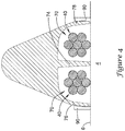
- the electrical pathway for grounding the rotating shaft 4 may be further understood with reference to Figure 3 .
- the electrical pathway may include a grounding member, such as the grounding rope 40, formed of a conductive material, such as copper or a copper alloy.
- the grounding rope 40 which extends through a channel 70 of the rope guide 50, may be positioned against the conductive surface 6 of the rotating shaft 4 such that the rotating shaft 4 slides against the grounding rope 40 as the rotating shaft 4 is rotating.
- the grounding rope 40 may be formed of a plurality of twisted multi-filar strands of conductive material, such as copper, or a copper alloy wires. It will be appreciated that the twisted multi-filar strands may provide a self-cleaning functionality as the rotating shaft 4 slides relative to the grounding rope 40.
- grounding rope 40 may have a different configuration.
- grounding rope includes alternative configurations of a conductive grounding member such as a cable, wire, braid, band, strap or other elongate electrically conductive structure.
- the grounding rope 40 may include a first end 42 coupled to a component in the electrical box 22 and a second end 44 hanging over the rotating shaft 4 in the direction of rotation of the rotating shaft 4.
- the grounding rope 40 may have a length such that about 1 to 2 inches of the grounding rope 40 extends along the tangent line beyond the tangent between the conductive surface 6 and the grounding rope 40.
- the first end 42 of the grounding rope 40 may be secured to a rope holder 30 in the electrical box 22.
- the first end 42 of the grounding rope 40 may be clamped between two plates of the rope holder 30 in some instances.
- the electrical pathway may pass through the control box 24 to a grounding wire 36 to ground 38.
- the grounding rope 40 may be connected to ground 38 through the electrical pathway passing through the electrical box 22, and thus grounded.
- the first end 42 of the grounding rope 40 may be attached directly to ground 38 (e.g., a grounding post), or another component electrically coupled to ground 38, without being attached to the rope holder 30.
- Figure 4 illustrates channels 70 provided in the rope guide 50 configured to receive the grounding ropes 40 for positioning along the conductive surface 6 of the rotating shaft 4.
- a first channel 70 may be defined between a first side wall 76 on the first side of the guide segment 52 and a divider wall 74
- a second channel 70 may be defined between a second side wall 76 on the second side of the guide segment 52 and the divider wall 74.
- the channels 70 may extend parallel to one another to position the grounding ropes 40 around a portion of the circumference of the rotating shaft 4.
- the channels 70 may open out to the bottom of the guide segments 52 facing the conductive surface 6 of the rotating shaft 4.
- the shaft grounding apparatus 20 may be mounted proximate to the rotating shaft 4 to electrically ground the shaft 4 of the electric machine 2.
- the grounding rope 40 may be placed in contact with the circumferential surface 6 of the rotating shaft 4.
- the grounding rope 40 may be draped over the rotating shaft 4 with the free second end 44 of the grounding rope 40 extending in the direction of rotation of the rotating shaft 4.
- multiple grounding ropes 40 may be draped over the rotating shaft 4 to position the ropes 40 in contact with the surface 6 of the rotating shaft 4.
- the adjustable rope guide 50 may also be positioned around a portion of the circumferential surface 6 of the rotating shaft 4 with the rope 40 extending along the channel 70 of the rope guide 50.
- a rope 40 may be positioned in and extend along each channel 70 of the rope guide 50.
- the rope(s) 40 may be circumferentially and/or axially constrained in the channel(s) 70 of the rope guide 50 along a portion of the circumference of the rotating shaft 4.
- the connector segment 56 and the articulating segments 52 of the rope guide 50 may be adjusted from a first minimum extent having a radius of curvature of 10 inches or less, 8 inches or less, or 6 inches or less to accommodate a similarly sized rotating shaft 4 to a second maximum extent having a radius of curvature of 10 inches or more, 12 inches or more, 14 inches or more, 16 inches or more, 18 inches or more, or 20 inches or more to accommodate a similarly sized rotating shaft 4.
- the articulating segments 52 may be adjusted to extend substantially flat, thus accommodating rotating shafts 4 having an infinitely large diameter.
- the rope guide 50 may be mounted to a range of sizes of rotating shafts 4, such as shafts 4 having diameters in the range of 6 to 36 inches, in the range of 6 to 24 inches, in the range of 6 to 20 inches, in the range of 6 to 18 inches, in the range of 6 to 16 inches, in the range of 6 to 14 inches, or in the range of 6 to 12 inches, in some instances.
- the rope guide 50 may guide the grounding rope(s) 40 along the rotating surface 6 of the rotating shaft 4.
- the grounding rope(s) 40 may be electrically grounded (e.g., connected to ground) to draw stray electrical voltage off of the rotating shaft 4 to prevent electrical current flow through bearings and/or other components of the electric machine 2 which could adversely affect the electric machine 2.
- FIG 5 is a schematic view of an electric generator 91 that may be considered as being representative of the electric machine 2.
- the electric generator 91 includes a turbine 93 and a generator 95.
- the rotating shaft 4 extends between the turbine 93 and the generator 95, and rotates therewith to transfer rotational energy between the turbine 93 and the generator 95.
- a constant monitoring signal acquisition assembly 97 is operably coupled with a shaft grounding assembly 99 that may, for example, be representative of the grounding assemblies discussed with respect to Figures 1-4 .
- the constant monitoring signal acquisition assembly 97 may, for example, include one or more electrical sensors that are configured to sense one or more electrical parameters pertaining to stray voltages within the rotating shaft 4.
- a constant monitoring shaft monitoring assembly 101 is operably coupled with a shaft contact assembly 103 that may, for example, be in sliding contact with the rotating shaft 4 but not be in electrical contact with ground (i.e., electrically isolated from ground).
- the constant monitoring shaft monitoring assembly 101 may, for example, include one or more electrical sensors that are configured to sense one or more electrical parameters pertaining to stray voltages within the rotating shaft 4.
- a conduit 105 permits the constant monitoring signal acquisition assembly 97 to communicate with the constant monitoring shaft monitoring assembly 101 and in some cases allows the constant monitoring signal acquisition assembly 97 and/or the constant monitoring shaft monitoring assembly 101 to communicate with a remote control center, such as a remote control room or control board, for example.
- FIG 6 is a schematic illustration of a monitoring system 81 in accordance with embodiments of the disclosure.
- the monitoring system 81 may be included with the electric machine 2 ( Figure 1 ) and/or the electric generator 91 of Figure 5 .
- the monitoring system 81 may be used with other devices that include a rotating shaft susceptible to stray voltages in the rotating shaft with or without a grounding apparatus.
- the monitoring system 81 may be considered as being a stand-alone monitoring system or an add-on or retro-fit addition to the grounding apparatus described with respect to Figures 1-4 .
- the monitoring system 81 includes a conductive member, such as the grounding member 40, that is configured to make sliding electrical contact with the rotating shaft 4 and that is configured to be connected to ground if used as a grounding member for the rotating shaft 4.
- An electrical sensor 85 is configured to be coupled with the grounding member 40 in order to detect an electrical parameter that provides an indication of electricity flowing from the rotating shaft 4 to ground through the grounding member 40.
- the electrical sensor 85 is an electrical current sensor.
- the electrical sensor 85 is an electrical voltage sensor.
- a processor 82 is operably coupled with the electrical sensor 85 and is configured to receive and analyze data from the electrical sensor 85.
- the electrical sensor 85 is configured to periodically provide the detected electrical parameter to the processor at a sampling rate and for a sampling period that is related to a rotation speed of the rotating shaft.
- the electrical sensor 85 is configured to periodically sample for a sampling period of time (i.e., a sampling period), and then to not sample for a subsequent period of time (i.e., a non-sampling period).
- the electrical sensor 85 may be configured to sense an electrical parameter (e.g., current or voltage) for a sampling period directly followed by a non-sampling period in which the electrical parameter (e.g., current or voltage) is not being sampled).
- sampling periods may alternate with non-sampling periods.
- each non-sampling period may be greater than each sampling period.
- each non-sampling period may be 5 time or more, 10 times or more, or 20 times or more, each sampling period.
- a memory 88 is operably coupled with the processor 82 and is configured to store information processed by the processor 82 that is representative of data provided by the electrical sensor 85.
- the memory 88 may represent short-term memory being used by the processor 82 for buffering incoming data from the electrical sensor 85. In some instances, the memory 88 may also be used for longer term storage of information that is representative of data provided by the electrical sensor 85.
- the electrical sensor 85 detects the electrical parameter at a sampling rate that provides enough data points per second to capture any anomalous or threshold condition that may be occurring.
- the processor 82 accepts data from the electrical sensor 85 for a sampling period that covers one or more complete revolutions of the rotating shaft 4.
- no data is collected from the electrical sensor 85 for a period of time directly after the sampling period (i.e., a non-sampling period), the period of time of the non-sampling period being longer than the sampling period.
- the period of time during which no data is collected from the electrical sensor 85 is as long as or longer than the period of time for which data is collected from the electrical sensor 85.
- a snapshot of data from the electrical sensor 85 may be stored and analyzed by the processor 82 during a first time interval, directly followed by a second time interval in which the data from the electrical sensor 85 is not being stored and analyzed by the processor 82. These periods of time may be continuously repeated, resulting in periodic analysis of snapshots of data at temporally spaced apart time intervals.
- the first time interval may be greater than or equal to the second time interval, or greater than the second time interval.
- the first time interval may be less than or equal to the second time interval, or less than the second time interval.
- the first time interval may be equal to the second time interval.
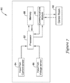
- FIG 7 is a schematic illustration of a monitoring system 80 in accordance with embodiments of the disclosure.
- the monitoring system 80 may be built into the electric machine 2 ( Figure 1 ).
- the monitoring system 80 may be used with other devices that include a rotating shaft susceptible to stray voltages in the rotating shaft with or without a grounding system.
- the monitoring system 80 may be considered as being a stand-alone monitoring system or an add-on or retro-fit addition to the grounding apparatus described with respect to Figures 1-4 .
- the monitoring system 80 includes the processor 82 that may be configured to receive data from a current sensor and thus may be operably coupled with an INPUT FROM CURRENT SENSOR 84.
- the processor 82 may be configured to receive data from a voltage sensor and thus may be operably coupled with an INPUT FROM VOLTAGE SENSOR 86.
- the INPUT FROM CURRENT SENSOR 84 and/or the INPUT FROM VOLTAGE SENSOR 86 may each independently represent a data channel providing data to the processor 82.
- the memory 88 may be operably coupled with the processor 82 and may, for example, be used to store, e.g., buffer, data provided directly from the INPUT FROM CURRENT SENSOR 84 and/or the INPUT FROM VOLTAGE SENSOR 86. In some cases, the memory 88 may also store data that has been processed by the processor 82 and thus may, for example, be representative of data that was provided from the INPUT FROM CURRENT SENSOR 84 and/or the INPUT FROM VOLTAGE SENSOR 86.
- a communications module 90 may be operably coupled to the processor 82 in order to communicate data to a location remote from the electric machine 2, such as a control room 92. In some cases, the communications module 90 may be used for receiving instructions and other data from the control room 92.
- FIG 8 is a schematic illustration of a monitoring system 94 in accordance with embodiments of the disclosure.
- the monitoring system 94 may be included with the electric machine 2 ( Figure 1 ).
- the monitoring system 94 may be used with other devices that include a rotating shaft susceptible to stray voltages in the rotating shaft with or without a grounding apparatus.
- the monitoring system 94 may be considered as being a stand-alone monitoring system or an add-on or retro-fit addition to the grounding apparatus described with respect to Figures 1-4 .
- the monitoring system 94 includes the processor 82 and the memory 88 that is operably coupled with the processor 82, much as described with respect to the monitoring system 80 illustrated in Figure 7 .
- the monitoring system 94 includes one or more sensors for sensing one or more electrical parameters, such as an electrical current sensor 96 and an electrical voltage sensor 98, each of which are operably coupled with the processor 82 such that the processor 82 may receive data from each of the current sensor 96 and the voltage sensor 98.
- the communications module 90 permits communication between the monitoring system 94 and the control room 92.
- the current sensor 96 may be any sensor that is configured to sense an electrical current. In some cases, the current sensor 96 may be a Hall effect sensor, but this is not required in all cases.
- the voltage sensor 98 may be any sensor that is configured to detect an electrical voltage.
- the monitoring system 94 may include only one of the current sensor 96 and the voltage sensor 98, and be configured to calculate an electrical voltage based on a sensed electrical current from the current sensor 96 or calculate an electrical current based on a sensed electrical voltage from the voltage sensor 98.
- an electrical shunt having a 1 Ohm resistor may be used such that electrical current equals electrical voltage, as described below.
- FIG 9 is a schematic illustration of an assembly 100 that includes the electric machine 2 ( Figure 1 ) in combination with a monitoring system 102.
- the monitoring system 102 includes the current sensor 96 disposed proximate or otherwise relative to the conductive grounding member 40 in such a way as to enable the current sensor 96 to sense or detect a current flowing in the grounding member 40.
- the monitoring system 102 also includes the voltage sensor 98 disposed proximate or otherwise relative to an isolated contact member 61 in such a way as to enable the voltage sensor 98 to sense or detect a voltage within the rotating shaft 4 ( Figure 1 ).
- the isolated contact member 61 may be a second grounding rope 40 that is electrically isolated from ground.
- the isolated contact member 61 may include an electrical shunt that is connected with the grounded grounding rope 40.
- a shunt may be used to determine current and/or voltage. It will be appreciated that since there is a well-known relationship between current and voltage, an appropriately sized shunt may permit determination of current and voltage, particularly if a 1 ohm shunt is utilized.
- the voltage sensor 98 may be a single voltage sensor or may be a pair (or more) of distinct voltage sensors, and may be configured to sense or detect a voltage within the rotating shaft 4 at two different locations on the rotating shaft 4, such as but not limited to a turbine end and an excitor end of the rotating shaft 4.
- the monitoring system 102 may, for example, include a processing module 104 that houses the processor 82, the memory 88 and the communications module 90 as discussed with respect to Figures 7 and 8 . It is contemplated that in some cases, the processing module 104 may include a display 91 that is operably coupled to the processor 82 such that sensed electrical voltages and/or current data, errors and/or warnings pertaining to potential anomalous or threshold conditions may be visibly displayed, for example.
- the processor 82 may be configured to analyze a snapshot of data from a first electrical sensor sensing a first electrical parameter, such as the current sensor 96 in order to look for potential anomalous or threshold conditions.
- the first electrical sensor may instead be a voltage sensor.
- a snapshot of data may be defined as data collected over a particular length of time, such as a second, or a fraction of a second.
- a snapshot of data from the first sensor may be collected or otherwise recorded for a first interval of time (i.e., first sampling period) and buffered in short term memory and a snapshot of data from the second sensor (e.g., the voltage sensor 98) may be collected or otherwise recorded and buffered in short term memory for a second interval of time (i.e., second sampling period).
- the second interval of time may be different than (e.g., shorter than or longer than) the first interval of time.
- the second interval of time may at least partially overlap with the first interval of time. In some instances, the second interval of time falls completely within the first interval of time.
- the first sensor may be the voltage sensor 98 and the second sensor may be the current sensor 96.
- a potential anomalous or threshold condition may be a current spike that lasts longer than a particular length of time, or perhaps a current spike that reaches a current level that exceeds a threshold current value. These thresholds may be programmed into the processor 82, or may be manually entered into the monitoring system 102. In some cases, a potential anomalous or threshold condition may not be related to a current spike, but may instead pertain to an instruction received from the control room 92 ( Figure 6 ), requesting additional information from the monitoring system 102.
- the processor 82 may calculate one or more values that are representative of the snapshot, and may save the one or more representative values to the memory 88. Any variety of representative values may be calculated and saved. For example, the processor 82 may calculate an average current value and/or a peak current value. In some cases, the processor 82 may also conduct waveform analysis of the snapshot of data from the current sensor 96 in order to look for particular patterns that indicate particular issues. For example, a saw tooth waveform with a slow rise and subsequent rapid discharge can indicate the build-up and release of static electricity on the shaft 4.
- the processor 82 may save the snapshot of data from the current sensor 86 to the memory 88, and may then analyze a corresponding snapshot of data from a second electrical sensor such as the voltage sensor 98.
- analyzing a corresponding snapshot of data from the voltage sensor 98 includes retrieving the data from a buffer that temporarily stores the data as it is provided by the voltage sensor 98, and in particular, retrieving data from a specific time interval that falls at least partially within the time interval corresponding to the snapshot of data from the current sensor 96.
- the first electrical sensor may instead be a voltage sensor and the second electrical sensor may instead be a current sensor, if desired. It will be appreciated that in some cases, particularly if the voltage sensor 98 is sampling at a higher sampling rate, that the snapshot of data from the voltage sensor 98 may include additional information pertaining to an anomalous or threshold condition seen in the snapshot of data from the current sensor 96.
- the current sensor 96 may be configured to sample at a first sampling rate and the voltage sensor 98 may be configured to sample at a second sampling rate that is higher than the first sampling rate.
- a first electrical sensor such as the current sensor 96 may sample essentially continuously at the first sampling rate while a second electrical sensor such as the voltage sensor 98 may sample periodically at the second sampling rate.
- Continuous sampling may be defined as sampling over a relatively long period of time. It will be appreciated that strictly speaking, digital sampling, as opposed to analog sampling, occurs as distinct samples occurring very rapidly one after another. For the purposes of this disclosure, digital sampling will be referred to as being continuous if it occurs over a relatively long period of time.
- Continuous sampling may also be defined as sampling that occurs at a sampling rate that is fast enough to reliably witness or otherwise capture data pertaining to a majority of potential recurring events. This contrasts with periodical sampling, such as may be done via the voltage sensor 98, which may sample at a high sampling rate for a short period of time, followed by a period of time without sampling, followed by a short period of sampling again, and so on. In some instances, the period of time without sampling may be longer than the short period of time while sampling.
- the sampling period (how long the current sensor 96 and/or the voltage sensor 98 samples) may be at least a function of how rapidly the rotating shaft 4 is rotating. Because events pertaining to a rotating shaft are cyclic in nature, in some cases a sampling period may be defined in terms of how long it takes for the rotating shaft 4 to make at least one complete revolution, or perhaps several complete revolutions. In some cases, the sampling rate may be a function of how frequently it is necessary to sample in order to catch any significant event occurring with respect to stray voltages exiting the rotating shaft 4. In some cases, particularly for the current sensor 96, this may mean sampling at a sampling rate of 100 samples per second or more, or perhaps at a sampling rate of 1000 samples per second or more.
- the current sensor 96 may be programmed or otherwise configured to sample (detect current) at a first sampling rate that ranges from about 10 kiloHz (kHz) to about 200 kHz, meaning 10,000 samples per second to about 200,000 samples per second. In some cases, the current sensor 96 may be programmed or otherwise configured to sample at a first sampling rate that ranges from about 50 kHz (50,000 samples per second) to about 150 kHz (150,000 samples per second). In a particular example, the current sensor 96 may be programmed or otherwise configured to sample at a first sampling rate that is about 100 kHz (100,000 samples per second) or more.
- the current sensor 96 may be programmed or otherwise configured to sample at a first sampling rate that is about 10 kHz (10,000 samples per second) or more, about 20 kHz (20,000 samples per second) or more, , about 40 kHz (40,000 samples per second) or more, about 60 kHz (60,000 samples per second) or more, about 80 kHz (80,000 samples per second) or more, about 120 kHz (120,000 samples per second) or more, about 140 kHz (140,000 samples per second) or more, about 160 kHz (160,000 samples per second) or more, about 180 kHz (180,000 samples per second) or more, or, about 200 kHz (200,000 samples per second) or more.
- the first sampling rate may vary, depending on a variety of variables including but not limited to the rotating speed of the rotating shaft 4.
- the voltage sensor 98 may be programmed or otherwise configured to sample (detect voltage) periodically. In some cases, the voltage sensor 98 may turn itself on for a brief period of time to sample, then turn itself off for a subsequent period of time in which the voltage sensor 98 does not sample. In some cases, the voltage sensor 98 may stay on, and the processor 82 may, for example, analyze data coming from the voltage sensor 98 for a brief period of time corresponding to the sampling time (i.e., sampling period), followed by a subsequent period of time in which the processor 82 ignores or otherwise does not analyze the data coming from the voltage sensor 98 (i.e., non-sampling period).
- the voltage sensor 98 may be programmed or otherwise configured to sample at the second sampling rate intermittently, such as for a fraction of a second per each second (i.e., for only a portion of each second). In some cases, the voltage sensor 98 may be programmed or otherwise configured to sample for about 0.02 seconds per each second to about 0.1 seconds per each second (i.e., sampling period), thereby ensuring data from at least one complete revolution for a shaft revolving at 3600 RPM. In some cases, the voltage sensor 98 may be programmed or otherwise configured to sample at the second sampling rate for a period of time ranging from 0.01 seconds per each second to 0.5 seconds per each second.
- the voltage sensor 98 is not sampling for a subsequent period of time (i.e., a non-sampling period) ranging from 0.5 seconds per each second to 0.99 seconds per each second.
- the voltage sensor 98 may be programmed or otherwise configured to sample at the second sampling rate for a period of time ranging from 0.05 seconds per each second to 0.25 seconds per each second.
- the voltage sensor 98 is not sampling for a subsequent period of time (i.e., a non-sampling period) ranging from 0.75 seconds per each second to 0.95 seconds per each second.
- the voltage sensor 98 may be programmed or otherwise configured to sample at the second sampling rate for a period of time ranging of about 0.1 seconds per each second. In this case, the voltage sensor 98 may be programmed or otherwise configured to not sample for a subsequent period of time (i.e., a non-sampling period) of about 0.9 seconds per each second. In some examples, the voltage sensor 98 may be programmed or otherwise configured to sample at the second sampling rate for about 50% or less, about 40% or less, about 30% or less, about 25% or less, about 20% or less, about 15% or less, about 10% or less, or about 5% or less of each second.
- the voltage sensor 98 may be programmed or otherwise configured to sample at a second sampling rate that ranges from 10 megaHz (MHz) to 100 MHz (10,000,000 samples per second to 100,000,000 samples per second). In some cases, the voltage sensor 98 may be programmed or otherwise configured to sample at a second sampling rate that ranges from 20 MHz (20,000,000 samples per second) to 80 MHz (80,000,000 samples per second). In a particular example, the voltage sensor 98 may be programmed or otherwise configured to sample at a second sampling rate that is about 20 MHz (20,000,000 samples per second) or more. In another particular example, the voltage sensor 98 may be programmed or otherwise configured to sample at a second sampling rate of about 40 MHz (40,000,000 samples per second) or more.
- the voltage sensor 98 may be programmed or otherwise configured to sample at a second sampling rate that is about 10 MHz (10,000,000 samples per second) or more, 30 MHz (30,000,000 samples per second) or more, 50 MHz (50,000,000 samples per second) or more, 60 MHz (60,000,000 samples per second) or more, 80 MHz (80,000,000 samples per second) or more, or 100 MHz (100,000,000 samples per second) or more.
- the corresponding snapshot of data from the voltage sensor 98 will still be analyzed by the processor 82. It will be appreciated that the snapshot of data from the voltage sensor 98 will at least partially temporally overlap the snapshot of data from the current sensor 96. In some cases, the snapshot of data from the voltage sensor 98 will temporally fit entirely within the snapshot of data from the current sensor 96. For example, if the snapshot of data from the current sensor 96 represents one second of time, the snapshot of data from the voltage sensor 96 may represent a fraction or portion of that same second of time.
- some transient events may be too short-lived to be visible in the current data that is sampled at the first sampling rate but may be caught in the voltage data that is sampled at the second, higher sampling rate.
- the snapshot of data from the voltage sensor 98 may be saved into the memory 88 for subsequent study.
- the processor 82 may calculate one or more values that are representative of the snapshot, and may save the one or more representative values to the memory 88. Any variety of representative values may be calculated and saved. For example, the processor 82 may calculate an average voltage value and/or a peak voltage value.
- the processor 82 may also conduct waveform analysis of the snapshot of data from the voltage sensor 98 in order to look for particular patterns that indicate particular issues. For example, a saw tooth waveform with a slow rise and subsequent rapid discharge indicates the build-up and release of static electricity.
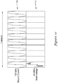
- Figure 10 is a graphical representation of illustrative sampling rates and corresponding data collected over a one second period of time. It is understood that this graphical representation would be repeated for subsequent periods of time.
- the upper graph 110 shows a current sampling rate of 100 kHz (100,000 data points or samples per second) and is indicative of data that may, for example, be collected continuously by the current sensor 96.
- the lower graph 112 shows a voltage sampling rate of 40 MHz (40,000,000 data points or samples per second), but only for 1/10 th of a second (i.e. for 0.1 seconds of each second) and is indicative of data that may, for example, be collected by the voltage sensor 98 intermittently or periodically.
- any potential event will likely repeat itself.
- the 1/10 th of a second that voltage data is collected still represents six full shaft rotations.
- a 1/10 th of a second represents three full shaft rotations, or one full shaft rotation for a shaft rotating at 600 RPM.
- the sampling rates and/or the relative duration of time that voltage data is collected may vary in accordance with shaft rotation speed. In some cases, the sampling rates and/or the relative duration of time that voltage data is collected may increase in order to obtain additional data regarding a particular event once that particular event has been identified or suspected.
- FIG 11 is a flow diagram showing a method of monitoring stray electricity in and/or grounding performance for a rotating conductive shaft (such as the rotating shaft 4 shown in Figure 1 ) in a device (such as the electrical machine 2 shown in Figure 1 ) that includes a grounding apparatus.
- data may be continuously received at a first sampling rate from a current sensor (such as the current sensor 96) that is operably coupled with the grounding apparatus.
- Data may be periodically or intermittently received at a second sampling rate from a voltage sensor (such as the voltage sensor 98) configured to sense a voltage within the rotating shaft, the second sampling rate being higher than the first sampling rate, as indicated at block 116.
- a snapshot of data from the current sensor may be analyzed, looking for potential events such as anomalous or threshold conditions.
Landscapes
- Physics & Mathematics (AREA)
- General Physics & Mathematics (AREA)
- Engineering & Computer Science (AREA)
- Power Engineering (AREA)
- Automation & Control Theory (AREA)
- Testing Of Short-Circuits, Discontinuities, Leakage, Or Incorrect Line Connections (AREA)
- Control Of Electric Motors In General (AREA)
- Motor Or Generator Frames (AREA)
Claims (14)
- Wellenerdungs- und -überwachungssystem für eine Vorrichtung (2, 91) mit einer rotierenden Welle (4), wobei das Wellenerdungs- und -überwachungssystem Folgendes aufweist:ein Erdungselement (40), das zum Herstellen von elektrischem Gleitkontakt mit der rotierenden Welle gestaltet ist, wobei das Erdungselement gestaltet ist, um mit Erde (38) verbunden zu sein;einen elektrischen Sensor (85, 96), der mit dem Erdungselement (40) gekoppelt ist und zum Erfassen eines elektrischen Parameters gestaltet ist, der auf durch das Erdungselement fließende Elektrizität hinweist, wobei der Sensor (85) zum periodischen Abtasten für eine Abtastzeitspanne, die als die Abtastperiode bezeichnet wird, und dann zum Nichtabtasten für eine nachfolgende Zeitspanne, die als eine Nichtabtastperiode bezeichnet wird, gestaltet ist,einen Prozessor (82), der funktionell mit dem elektrischen Sensor gekoppelt ist, wobei der Prozessor zum Empfangen und Analysieren von den elektrischen Parameter repräsentierenden Daten von dem elektrischen Sensor gestaltet ist;wobei der Prozessor ferner zum periodischen Analysieren der den elektrischen Parameter repräsentierenden Daten von dem elektrischen Sensor für die Abtastperiode und zum Nichtanalysieren der den elektrischen Parameter repräsentierenden Daten für eine Zeitspanne unmittelbar nach der Abtastperiode gestaltet ist, wobei die Abtastperiode mit einer Drehzahl der rotierenden Welle in Beziehung steht; undeinen Speicher (88), der funktionell mit dem Prozessor gekoppelt ist und zum Speichern von durch den Prozessor verarbeiteten Daten, die für die von dem elektrischen Sensor bereitgestellten Daten repräsentativ sind, gestaltet ist.
- Wellenerdungs- und -überwachungssystem nach Anspruch 1, wobei die Abtastperiode größer oder gleich einer vollständigen Umdrehung der rotierenden Welle ist.
- Wellenerdungs- und -überwachungssystem nach Anspruch 1 oder Anspruch 2, wobei die Zeitspanne unmittelbar nach der Abtastperiode, in welcher der Prozessor die den elektrischen Parameter repräsentierenden Daten nicht analysiert, länger als die Abtastperiode ist, in welcher der Prozessor die den elektrischen Parameter repräsentierenden Daten analysiert.
- Wellenerdungs- und -überwachungssystem nach einem der vorhergehenden Ansprüche, wobei der Prozessor zum Analysieren der den elektrischen Parameter repräsentierenden Daten von dem elektrischen Sensor für eine Abtastperiode, die von 0,01 Sekunden pro jeder Sekunde bis 0,5 Sekunden pro jeder Sekunde reicht, gestaltet ist und der Prozessor zum Nichtanalysieren der den elektrischen Parameter repräsentierenden Daten von dem elektrischen Sensor für eine nachfolgende Zeitspanne, die von 0,5 Sekunden pro jeder Sekunde bis 0,99 Sekunden pro jeder Sekunde reicht, gestaltet ist.
- Wellenerdungs- und -überwachungssystem nach einem der vorhergehenden Ansprüche, wobei der Prozessor zum Analysieren der den elektrischen Parameter repräsentierenden Daten von dem elektrischen Sensor für eine Abtastperiode, die von 0,05 Sekunden pro jeder Sekunde bis 0,25 Sekunden pro jeder Sekunde reicht, gestaltet ist und der Prozessor zum Nichtanalysieren der den elektrischen Parameter repräsentierenden Daten von dem elektrischen Sensor für eine nachfolgende Zeitspanne, die von 0,75 Sekunden pro jeder Sekunde bis 0,95 Sekunden pro jeder Sekunde reicht, gestaltet ist.
- Überwachungssystem für eine Vorrichtung (2, 91), die eine rotierende Welle (4) und ein Erdungselement (40), das in elektrischem Kontakt mit der rotierenden Welle positioniert ist, hat, wobei das Überwachungssystem Folgendes aufweist:einen Stromsensor (96), der funktionell mit dem Erdungselement (40) gekoppelt ist und zum Erfassen eines durch das Erdungselement fließenden elektrischen Stroms gestaltet ist, wobei der Stromsensor ferner zum Abtasten mit einer ersten Abtastrate für ein erstes Abtastintervall gestaltet ist;einen Spannungssensor (98), der zum Erfassen einer elektrischen Spannung in der rotierenden Welle gestaltet ist, wobei der Spannungssensor ferner zum periodischen Abtasten mit einer zweiten Abtastrate für ein zweites Abtastintervall und dann zum Nichtabtasten für eine nachfolgende Zeitspanne gestaltet ist,wobei die zweite Abtastrate höher ist als die erste Abtastrate und das erste Abtastintervall länger als das zweite Abtastintervall und das zweite Abtastintervall überlappend ist;einen Prozessor (82), der funktionell mit dem Stromsensor und mit dem Spannungssensor gekoppelt ist und zum Empfangen von Daten, die für elektrischen Strom, der durch den Stromsensor erfasst wird, bezeichnend sind, und von Daten, die für elektrische Spannung, die durch den Spannungssensor erfasst wird, bezeichnend sind, gestaltet ist;wobei der Prozessor zum Analysieren der Daten von dem Stromsensor und der Daten von dem Spannungssensor gestaltet ist; undeinen Speicher (88), der funktionell mit dem Prozessor gekoppelt ist und zum Speichern von Informationen gestaltet ist, die für die Daten von dem Stromsensor und die Daten von dem Spannungssensor repräsentativ sind.
- Überwachungssystem nach Anspruch 6, wobei der Prozessor (82) ferner zum Analysieren einer Momentaufnahme von Daten von dem Stromsensor (96) während der Abtastperiode gestaltet ist, um eine potenziell anomale oder Schwellenbedingung zu erkennen.
- Überwachungssystem nach Anspruch 6, wobei, wenn der Prozessor anhand der Momentaufnahme von Daten von dem Stromsensor keine potenziell anomale oder Schwellenbedingung erkennt, der Prozessor ferner zum Abspeichern von ein oder mehr Werten, die für die Momentaufnahme von Daten von dem Stromsensor repräsentativ sind, in dem Speicher gestaltet ist.
- Überwachungssystem nach Anspruch 6, wobei, wenn der Prozessor anhand der Momentaufnahme von Daten von dem Stromsensor eine potenziell anomale oder Schwellenbedingung erkennt, der Prozessor ferner zum Abspeichern von ein oder mehr Werten, die für die Momentaufnahme von Daten von dem Stromsensor repräsentativ sind, in dem Speicher und zum Analysieren einer zeitlich abgeglichenen Momentaufnahme von Daten von dem Spannungssensor, um zusätzliche Informationen bezüglich der potenziell anomalen oder Schwellenbedingung bereitzustellen, gestaltet ist.
- Wellenerdungs- und -überwachungssystem für eine Vorrichtung (2, 91) mit einer rotierenden Welle (4), wobei das Wellenerdungs- und -überwachungssystem Folgendes aufweist:ein Erdungselement (40), das für Gleitkontakt mit der rotierenden Welle und zum Herstellen von elektrischem Kontakt mit der rotierenden Welle gestaltet ist, wobei das Erdungselement gestaltet ist, um mit Erde (38) verbunden zu sein;ein isoliertes Kontaktelement (61), das für Gleitkontakt mit der rotierenden Welle gestaltet ist, wobei das isolierte Kontaktelement elektrisch von der Erde isoliert ist; unddas Überwachungssystem nach Anspruch 6;wobei der Stromsensor mit dem Erdungselement gekoppelt ist, um einen von der rotierenden Welle durch das Erdungselement zur Erde fließenden elektrischen Strom zu erfassen, und der Spannungssensor mit dem isolierten Kontaktelement gekoppelt ist, um eine elektrische Spannung in der Welle zu erfassen.
- Verfahren zur Überwachung einer rotierenden leitenden Welle (4) in einer Vorrichtung (2, 91) mit einer Erdungsvorrichtung (40), wobei das Verfahren Folgendes aufweist:Empfangen von Daten mit einer ersten Abtastrate während eines ersten Abtastintervalls von einem Stromsensor (85, 96), der funktionell mit der Erdungsvorrichtung gekoppelt ist;periodisches Empfangen von Daten mit einer zweiten Abtastrate während eines zweiten Abtastintervalls von einem Spannungssensor (85, 98), der zum Erfassen einer Spannung in dem rotierenden Schaft gestaltet ist, und dann NichtAbtasten für eine nachfolgende Zeitspanne, wobei die zweite Abtastrate höher als die erste Abtastrate ist;Analysieren einer Momentaufnahme von Daten von dem Stromsensor zum Erkennen einer potenziell anomalen oder Schwellenbedingung; und,wenn in der Momentaufnahme von Daten von dem Stromsensor eine potenzielle anomale oder Schwellenbedingung gesehen wird, Analysieren einer Momentaufnahme von Daten von dem Spannungssensor;wobei die Momentaufnahme von Daten von dem Spannungssensor, die analysiert wird, zumindest teilweise zeitlich mit der Momentaufnahme von Daten von dem Stromsensor, die analysiert wurde, abgeglichen ist.
- Verfahren nach Anspruch 11, wobei, wenn in der Momentaufnahme von Daten von dem Stromsensor eine potenziell anomale oder Schwellenbedingung gesehen wird, Speichern der Momentaufnahme von Daten von dem Stromsensor zur zukünftigen Analyse.
- Verfahren nach Anspruch 11, wobei, wenn in der Momentaufnahme von Daten von dem Stromsensor keine potenziell anomale oder Schwellenbedingung gesehen wird, Abspeichern repräsentativer Informationen, die sich auf die Momentaufnahme von Daten von dem Stromsensor beziehen, im Speicher (88).
- Verfahren nach einem der Ansprüche 11 bis 13, wobei die erste Abtastperiode die zweite Abtastperiode zumindest teilweise zeitlich überlappt.
Applications Claiming Priority (2)
| Application Number | Priority Date | Filing Date | Title |
|---|---|---|---|
| US201662277166P | 2016-01-11 | 2016-01-11 | |
| PCT/US2017/012802 WO2017123521A1 (en) | 2016-01-11 | 2017-01-10 | Monitoring system for grounding apparatus |
Publications (2)
| Publication Number | Publication Date |
|---|---|
| EP3403153A1 EP3403153A1 (de) | 2018-11-21 |
| EP3403153B1 true EP3403153B1 (de) | 2020-12-30 |
Family
ID=58016787
Family Applications (1)
| Application Number | Title | Priority Date | Filing Date |
|---|---|---|---|
| EP17704563.0A Not-in-force EP3403153B1 (de) | 2016-01-11 | 2017-01-10 | Überwachungssystem für erdungsvorrichtung |
Country Status (6)
| Country | Link |
|---|---|
| US (2) | US10371726B2 (de) |
| EP (1) | EP3403153B1 (de) |
| JP (1) | JP6756834B2 (de) |
| AU (1) | AU2017206696A1 (de) |
| CA (1) | CA3008957C (de) |
| WO (1) | WO2017123521A1 (de) |
Cited By (1)
| Publication number | Priority date | Publication date | Assignee | Title |
|---|---|---|---|---|
| WO2025237964A1 (de) * | 2024-05-14 | 2025-11-20 | AVL SET GmbH | Prüf- und messsystem und messaufbau |
Families Citing this family (10)
| Publication number | Priority date | Publication date | Assignee | Title |
|---|---|---|---|---|
| CA3114764A1 (en) | 2018-10-04 | 2020-04-09 | Cutsforth, Inc. | System and method for monitoring the status of one or more components of an electrical machine |
| CN113243063B (zh) | 2018-10-04 | 2023-11-07 | 科茨福斯有限公司 | 用于监控电机的一个或多个元件的状态的系统和方法 |
| ES3014066T3 (en) | 2018-12-21 | 2025-04-16 | Vestas Wind Sys As | Improvements relating to stray current detection in wind turbine generators |
| JP7579893B2 (ja) * | 2021-02-09 | 2024-11-08 | 日立Astemo株式会社 | 歪み量検出装置 |
| KR102878936B1 (ko) * | 2021-04-20 | 2025-10-30 | 한국전력공사 | 축 접지 장치, 이를 이용한 축 전원 감시 시스템 및 방법 |
| DE102021204636A1 (de) | 2021-05-07 | 2022-11-10 | Zf Friedrichshafen Ag | Prüfstand für ein Antriebsaggregat und Kontaktiervorrichtung zur elektrischen Kontaktierung einer Welle |
| KR102449375B1 (ko) * | 2022-06-30 | 2022-10-06 | 한국전진기술(주) | 콜렉터링 브러시간 이상 감지 시스템 |
| US20240361758A1 (en) * | 2023-04-27 | 2024-10-31 | General Electric Company | Devices and methods for sensor data analysis of transient errors |
| TWI890181B (zh) * | 2023-11-01 | 2025-07-11 | 國立臺灣大學 | 脈波電壓資訊擷取裝置及方法 |
| WO2025215602A1 (en) * | 2024-04-11 | 2025-10-16 | Troy Lance Timm | Shaft grounding system |
Family Cites Families (133)
| Publication number | Priority date | Publication date | Assignee | Title |
|---|---|---|---|---|
| US1307028A (en) | 1919-06-17 | For dynamo electric machines | ||
| US2935632A (en) | 1956-02-08 | 1960-05-03 | Jr Michael F Schmitz | Shunt for carbon brush |
| US3523288A (en) | 1968-03-20 | 1970-08-04 | Harris A Thompson | Brush wear indicator |
| US3534206A (en) | 1969-10-09 | 1970-10-13 | Carbone Corp The | Carbon brush assembly |
| US3641379A (en) | 1970-09-15 | 1972-02-08 | Black & Decker Mfg Co | Brush lead retainer |
| US4024525A (en) | 1976-01-07 | 1977-05-17 | Towmotor Corporation | Brush wear indicator |
| US4058804A (en) | 1976-03-11 | 1977-11-15 | General Electric Company | Signal monitoring system |
| US4121207A (en) | 1977-07-18 | 1978-10-17 | Towmotor Corporation | Switch for indicating brush wear |
| GB1541997A (en) | 1977-08-02 | 1979-03-14 | Towmotor Corp | Brush wear indicating means |
| US4272695A (en) | 1977-10-26 | 1981-06-09 | Towmotor Corporation | Brush wear indicator |
| US4329611A (en) | 1977-11-21 | 1982-05-11 | General Electric Company | Brushholder apparatus for dynamoelectric machine |
| US4344072A (en) | 1979-12-10 | 1982-08-10 | Harper Jr Harold L | Worn brush indicator |
| US4316186A (en) | 1980-02-06 | 1982-02-16 | Eltra Corporation | Brush wear detection and warning system |
| US4333095A (en) | 1980-02-19 | 1982-06-01 | Reliance Electric Company | Brush wear indicator |
| US4329683A (en) | 1980-09-04 | 1982-05-11 | General Electric Co. | Brush wear indicator for a dynamoelectric machine |
| US4344009A (en) | 1980-09-04 | 1982-08-10 | General Electric Co. | Brush wear indicator for a dynamoelectric machine brush |
| US4348608A (en) | 1980-09-04 | 1982-09-07 | General Electric Co. | Brush wear indicator |
| US4390870A (en) | 1981-06-15 | 1983-06-28 | General Electric Company | Interface circuit for brush wear indicator application |
| JPS5812556A (ja) | 1981-07-14 | 1983-01-24 | Hitachi Ltd | 集電装置の火花監視装置 |
| US4400638B1 (en) | 1981-08-20 | 1994-11-29 | Stromag Inc | Shaft mounted eddy current drive |
| US4536670A (en) | 1981-12-14 | 1985-08-20 | Morganite Incorporated | Electrical brushes with wear sensors |
| DE3211251C2 (de) | 1982-03-26 | 1985-09-26 | Steinbock Gmbh, 8052 Moosburg | Schaltungsanordnung zur Überwachung des Abnutzungsgrads von Kommutator-Kohlebürsten |
| US4528557A (en) | 1982-04-23 | 1985-07-09 | Helwig Carbon, Inc. | Brush wear indicator |
| US4420705A (en) | 1982-05-26 | 1983-12-13 | General Electric Company | Contact and terminal assembly for a brush wear indicator |
| US4513495A (en) | 1982-05-26 | 1985-04-30 | General Electric Company | Contact and terminal assembly for a brush wear indicator |
| NL8202816A (nl) | 1982-07-12 | 1984-02-01 | Josephus Bernardus Michael Ber | Werkwijze en inrichting voor het besturen van een borstel-kommutatorsamenstel van een electrische machine. |
| US4488078A (en) | 1982-08-18 | 1984-12-11 | General Electric Company | Brush wear detector |
| US4652783A (en) | 1982-11-10 | 1987-03-24 | Morganite Electrical Carbon Limited | Anchoring wear sensors in electrical brushing |
| JPS59108111A (ja) * | 1982-12-13 | 1984-06-22 | Hitachi Ltd | サンプルホ−ルド回路 |
| US4528556A (en) | 1983-02-14 | 1985-07-09 | Leesona Corporation | Defective motor brush detector |
| JPS6039337A (ja) | 1983-08-12 | 1985-03-01 | Hitachi Ltd | 刷子長さ監視装置の据付方法 |
| US4636778A (en) | 1983-10-03 | 1987-01-13 | Reliance Electric Company | Brush wear monitor |
| US4646001A (en) | 1983-11-21 | 1987-02-24 | Morganite Electrical Carbon Limited | Resistive wear sensors |
| DE3417711A1 (de) | 1984-05-12 | 1985-11-14 | Licentia Patent-Verwaltungs-Gmbh, 6000 Frankfurt | Vorrichtung zur ueberwachung und anzeige des abnutzungsgrads von kohlebuersten in stromrichtergespeisten gleichstrommaschinen |
| DE3509299A1 (de) | 1985-03-15 | 1986-09-25 | Heidelberger Druckmaschinen Ag, 6900 Heidelberg | Einrichtung zur zustandserkennung von kohlebuersten bei antrieben, insbesondere bei antrieben an druckmaschinen |
| US4723084A (en) | 1986-11-13 | 1988-02-02 | General Electric Company | Light conductor brush wear detector assembly |
| US4739208A (en) | 1986-11-13 | 1988-04-19 | General Electric Company | Brush assembly including brush wear detector |
| US4743787A (en) | 1986-11-13 | 1988-05-10 | General Electric Company | Brush wear indicator having variable light energy conductor path |
| CH674433A5 (de) * | 1986-11-19 | 1990-05-31 | Bbc Brown Boveri & Cie | |
| JPH0650329B2 (ja) * | 1988-07-13 | 1994-06-29 | 鐘紡株式会社 | 回転軸の電気的導通方法 |
| US4918348A (en) | 1988-12-14 | 1990-04-17 | Prestolite Electric Incorporated | Brush wear indicator |
| US4950933A (en) | 1989-08-03 | 1990-08-21 | Westinghouse Electric Corp. | Carbon brush holder utilizing a worn brush detector |
| US4977345A (en) | 1990-01-25 | 1990-12-11 | Westinghouse Electric Corp. | Spring mounted carbon brush wear indicator |
| US5256925A (en) | 1992-03-24 | 1993-10-26 | Cutsforth David L | Brush holder with improved spring clip arrangement |
| US5229817A (en) | 1992-03-27 | 1993-07-20 | Xerox Corporation | Apparatus for monitoring wear of a toner removal device |
| GB2266162B (en) | 1992-04-17 | 1996-02-07 | Asahi Optical Co Ltd | Zoom lens barrel with focal length detector |
| DE4307451A1 (de) | 1993-03-10 | 1994-09-15 | Bosch Gmbh Robert | Bürstenhalter für mechanisch kommutierte Elektromotoren |
| DE4315622C2 (de) | 1993-05-11 | 1997-01-16 | Schunk Kohlenstofftechnik Gmbh | Kohlebürste sowie Verfahren zum Anordnen und Befestigen einer Meldelitze in einer solchen |
| US5387831A (en) | 1993-05-27 | 1995-02-07 | Yang; Tai-Her | Low circulation loss compound brush |
| US5509625A (en) | 1993-12-21 | 1996-04-23 | United Technologies Corp. | Electrical brush-wear indicator |
| US5463264A (en) | 1994-07-19 | 1995-10-31 | Helwig Carbon Products, Inc. | Constant force brush holder assembly |
| US5731650A (en) | 1994-11-14 | 1998-03-24 | Lucas Aerospace Power Equipment Corp. | Dynamoelectric machine with brush wear sensor |
| KR0135179Y1 (ko) | 1995-05-02 | 1999-04-15 | 한순윤 | 카본 브러쉬 홀더 |
| JPH09182384A (ja) | 1995-12-27 | 1997-07-11 | Makita Corp | モータのブラシ摩耗報知装置 |
| US5739619A (en) | 1996-03-19 | 1998-04-14 | Life Cycle Engineering, Inc. | Electrical brush having a wear indicator |
| FR2751416B1 (fr) | 1996-07-17 | 1998-09-25 | Eurocopter France | Surveillance de l'usure de contacts electriques frottants et son application a la maintenance selon l'etat et/ou predictive d'un dispositif a contacts electriques frottants |
| US5753992A (en) | 1996-11-07 | 1998-05-19 | Delco Remy America Inc | Single piece brush fixture for dynamoelectric machine |
| US5870026A (en) | 1997-07-15 | 1999-02-09 | The Morgan Crucible Company Plc | Brush wear indicator |
| US7551288B1 (en) | 1997-10-28 | 2009-06-23 | Rockwell Automation Technologies, Inc. | System for monitoring bearing wear |
| US6111643A (en) | 1997-10-28 | 2000-08-29 | Reliance Electric Industrial Company | Apparatus, system and method for determining wear of an article |
| US6580511B1 (en) | 1997-10-28 | 2003-06-17 | Reliance Electric Technologies, Llc | System for monitoring sealing wear |
| US6197086B1 (en) | 1997-11-13 | 2001-03-06 | Bethlehem Steel Corporation | System and method for minimizing slag carryover during the production of steel |
| DE19755232B4 (de) | 1997-12-12 | 2008-12-24 | Continental Automotive Gmbh | Kraftstoffpumpe |
| US6598597B1 (en) | 1999-03-30 | 2003-07-29 | Geo S.R.L. | Method for cutting blocks of stone and frame cutting machine for carrying out said method |
| US6460013B1 (en) * | 1999-05-06 | 2002-10-01 | Paul I. Nippes | Shaft voltage current monitoring system for early warning and problem detection |
| US6255955B1 (en) | 1999-05-25 | 2001-07-03 | General Electric Company | Brush warning indicator and methods for indicating brush wear-out |
| US6281610B1 (en) | 1999-06-29 | 2001-08-28 | General Electric Company | Slip ring brush assembly and method |
| US6552467B1 (en) | 2000-04-21 | 2003-04-22 | Valeo Electrical Systems, Inc. | Integral noise filter within brush of electric motor |
| JP3510563B2 (ja) | 2000-05-16 | 2004-03-29 | 株式会社ミツバ | 燃料ポンプのブラシ組付け構造 |
| CN1606758A (zh) | 2000-08-31 | 2005-04-13 | 雷泰克公司 | 传感器和成像系统 |
| KR20040029306A (ko) * | 2000-11-08 | 2004-04-06 | 제너럴 일렉트릭 캄파니 | 필드 그라운드 검출용 시스템 및 필드 그라운드 고장 검출및 측정 방법 |
| DE10115267C2 (de) | 2001-03-28 | 2003-06-18 | Aloys Wobben | Verfahren zur Überwachung einer Windenergieanlage |
| EP1271716B1 (de) | 2001-06-28 | 2004-11-24 | Siemens Aktiengesellschaft | Vorrichtung zur Überwachung eines Schleifkontaktelements einer elektrischen Rotationsmaschine |
| WO2003052902A1 (en) | 2001-12-18 | 2003-06-26 | Cutsforth Products, Inc. | Brush holder adapted to be removed without stopping the machine |
| EP1482617B1 (de) | 2002-02-14 | 2006-09-20 | Yanmar Co., Ltd. | Stromgenerator und entsprechendes system |
| US7005964B2 (en) | 2002-04-08 | 2006-02-28 | P. J. Edmonson Ltd. | Dual track surface acoustic wave RFID/sensor |
| WO2004025316A1 (de) | 2002-09-10 | 2004-03-25 | Alstom Technology Ltd | Vorrichtung und verfahren zur überwachung und/oder analyse von elektrischen maschinen im betrieb |
| US7649470B2 (en) | 2002-09-10 | 2010-01-19 | Alstom Technology Ltd. | Method and apparatus for detection of brush sparking and spark erosion on electrical machines |
| CN100549636C (zh) | 2002-09-10 | 2009-10-14 | 阿尔斯托姆科技有限公司 | 检测在电机上轴系振动的方法和装置 |
| WO2004032309A1 (ja) | 2002-10-07 | 2004-04-15 | Mitsubishi Denki Kabushiki Kaisha | 車両用回転電機 |
| CZ12924U1 (cs) | 2002-10-21 | 2003-01-20 | Neva - Nekut & Müller Spol. S R.O. | Strojní rámová pila na dřevo |
| US6731042B1 (en) | 2002-12-13 | 2004-05-04 | Phoenix Electric Mfg. Co. | Constant force cartridge brush holder |
| CN100350682C (zh) | 2003-01-14 | 2007-11-21 | 苏州宝时得电动工具有限公司 | 电动机的碳刷磨损感测装置 |
| JP2004265180A (ja) | 2003-03-03 | 2004-09-24 | Hitachi Ltd | 監視機器装置 |
| US7010959B2 (en) | 2003-03-28 | 2006-03-14 | Schleifring Und Apparatebau Gmbh | Device and method for measuring mechanical path lengths by means of pneumatic pressure, in particular for sliding carbon contacts |
| CN1442683A (zh) | 2003-04-17 | 2003-09-17 | 上海交通大学 | 大型发电机定子绕组端部振动在线监测方法 |
| JP4334299B2 (ja) | 2003-08-22 | 2009-09-30 | 株式会社東芝 | 電気接点、電気接点摩耗検出装置およびその摩耗検出方法 |
| TWM255580U (en) | 2003-11-25 | 2005-01-11 | Taiwan Long Hawn Entpr Co | Safety alarm carbon brush socket |
| JP4413073B2 (ja) * | 2004-05-14 | 2010-02-10 | 株式会社ミノグループ | 電気回路の異常検出装置 |
| DE102004036805A1 (de) | 2004-07-29 | 2006-03-23 | Robert Bosch Gmbh | Elektrowerkzeug mit innerem Befestigungselement |
| CH697269B1 (de) | 2004-08-12 | 2008-07-31 | Alstom Technology Ltd | Verfahren und Vorrichtung zur Detektion von Streifstellen an rotierenden Maschinen. |
| US7218028B2 (en) | 2004-12-03 | 2007-05-15 | General Electric Company | Brush holder assembly for dynamoelectric machines |
| US7328130B2 (en) * | 2005-08-17 | 2008-02-05 | Xtek, Inc. | Data acquisition system for system monitoring |
| US7545072B2 (en) | 2005-10-13 | 2009-06-09 | Culsforth Products, Inc. | Resilient member for a brush holder assembly |
| DE102005061412A1 (de) | 2005-12-22 | 2007-06-28 | Robert Bosch Gmbh | Vorrichtung und Verfahren zur Überwachung der Abnutzung einer Bürste |
| DE102005062073A1 (de) | 2005-12-22 | 2007-07-05 | Schunk Motorensysteme Gmbh | Kohlebürstenanordnung |
| DE202006003418U1 (de) | 2006-03-04 | 2006-05-04 | Zahoransky Ag | Kontrolleinrichtung |
| US20070273165A1 (en) | 2006-05-25 | 2007-11-29 | Dave Beck | Impact sensor |
| US7485882B2 (en) | 2006-06-15 | 2009-02-03 | Siemens Energy, Inc. | Hand held magnetic induction thermography system |
| WO2008006655A1 (de) * | 2006-07-13 | 2008-01-17 | Alstom Technology Ltd | Verfahren und vorrichtung zur detektion von interlaminaren kurzschlüssen |
| JP4441735B2 (ja) * | 2006-09-08 | 2010-03-31 | 有限会社 ソフトロックス | サイクル運転加工機の加工工程の監視方法 |
| US8165552B2 (en) | 2006-09-29 | 2012-04-24 | Broadcom Corporation | Method and system for identifying radio frequency identification (RFID) tag location using a switchable coil |
| US8104810B2 (en) | 2006-11-01 | 2012-01-31 | Norgren Automotive Solutions, Inc. | Gripper having sensor for detecting displacement |
| JP2008212336A (ja) | 2007-03-02 | 2008-09-18 | Teizo Sato | 電気剃刀 |
| US7705744B2 (en) | 2007-05-24 | 2010-04-27 | Cutsforth Products, Inc. | Monitoring systems and methods for monitoring the condition of one or more components of an electrical device |
| US8618943B2 (en) | 2007-05-24 | 2013-12-31 | Cutsforth, Inc. | Brush holder assembly monitoring apparatus, assembly, system and method |
| US7709994B2 (en) | 2007-10-10 | 2010-05-04 | Mantle Elton L | Brush board for high current electric motor |
| DE102007055795A1 (de) | 2007-12-13 | 2009-06-18 | Alstom Technology Ltd. | Vorrichtung zur Überwachung von Bürsten, insbesondere von Schleifring- oder Kommutatorbürsten, an Elektromaschinen |
| US7880362B2 (en) | 2008-03-14 | 2011-02-01 | Cutsforth Products, Inc. | Brush holder assembly with spring clip |
| EP2112518A1 (de) | 2008-04-25 | 2009-10-28 | ALSTOM Technology Ltd | Bürstenabnutzungsüberwacher |
| KR100970338B1 (ko) * | 2008-11-07 | 2010-07-15 | 진기호 | 자동차용 스타터교환 경고장치 |
| US8047083B2 (en) | 2009-02-17 | 2011-11-01 | Black & Decker Corporation | Trigger assembly including a flexible bend sensor |
| US8159396B2 (en) | 2009-10-30 | 2012-04-17 | General Electric Company | Wireless proximity probe and method of operating same |
| JP5121914B2 (ja) * | 2010-12-02 | 2013-01-16 | 三菱電機株式会社 | 電動機制御装置、電気掃除機及び手乾燥装置 |
| US8558429B2 (en) | 2011-01-05 | 2013-10-15 | General Electric Company | Systems, methods, and apparatus for lifting brushes of an induction motor |
| US8618713B2 (en) | 2011-02-16 | 2013-12-31 | General Electric Company | Brush holder apparatus |
| DE102011005302B4 (de) | 2011-03-09 | 2012-10-31 | Schunk Bahn- Und Industrietechnik Gmbh | Verschleißerkennungssystem und Verfahren |
| GB201104155D0 (en) | 2011-03-11 | 2011-04-27 | Esdaco Bvba | Apparatus for monitoring of brushes in particular slipring or commutator brushes, on electrical machines |
| US8384266B2 (en) | 2011-03-29 | 2013-02-26 | General Electric Company | Brush wear detector system with wireless sensor |
| US8714860B2 (en) | 2011-08-05 | 2014-05-06 | Cutsforth, Inc. | Mounting fixture including an articulation joint |
| US8493707B2 (en) | 2011-08-05 | 2013-07-23 | Cutsforth, Inc. | Grounding rope guide for a dynamo-electric machine |
| US9088197B2 (en) * | 2011-09-07 | 2015-07-21 | General Electric Company | Shaft grounding system |
| US8972219B2 (en) | 2012-02-22 | 2015-03-03 | General Electric Company | Method and system of monitoring electrical brushes |
| US8836197B2 (en) | 2012-03-23 | 2014-09-16 | General Electric Company | Brush holder having radio frequency identification (RFID)temperature monitoring system |
| US9331555B2 (en) | 2012-11-05 | 2016-05-03 | General Electric Company | Apparatus, brush holder and system for monitoring brush wear |
| US9252643B2 (en) | 2013-03-14 | 2016-02-02 | Cutsforth, Inc. | System and method for monitoring the status of one or more components of an electrical machine |
| US9560729B2 (en) * | 2013-09-09 | 2017-01-31 | Cutsforth, Inc. | Grounding rope for a shaft grounding apparatus of a dynamo-electric machine |
| US9647404B2 (en) | 2014-06-10 | 2017-05-09 | General Electric Company | Brush holder apparatus and system |
| US9762014B2 (en) | 2014-06-10 | 2017-09-12 | General Electric Company | Brush holder apparatus and system |
| US9793670B2 (en) | 2014-06-10 | 2017-10-17 | General Electric Company | Brush holder apparatus and system |
| US9762015B2 (en) | 2014-06-10 | 2017-09-12 | General Electric Company | Brush holder apparatus and system |
| CA2985094C (en) | 2015-06-01 | 2022-03-22 | Cutsforth, Inc. | Brush wear and vibration monitoring |
| EP3635421A1 (de) * | 2017-06-05 | 2020-04-15 | Cutsforth Inc. | Überwachungssystem für erdungsvorrichtung |
-
2017
- 2017-01-10 CA CA3008957A patent/CA3008957C/en active Active
- 2017-01-10 JP JP2018533884A patent/JP6756834B2/ja not_active Expired - Fee Related
- 2017-01-10 US US15/402,455 patent/US10371726B2/en active Active
- 2017-01-10 AU AU2017206696A patent/AU2017206696A1/en not_active Abandoned
- 2017-01-10 WO PCT/US2017/012802 patent/WO2017123521A1/en not_active Ceased
- 2017-01-10 EP EP17704563.0A patent/EP3403153B1/de not_active Not-in-force
-
2019
- 2019-06-18 US US16/444,657 patent/US10649011B2/en active Active
Non-Patent Citations (1)
| Title |
|---|
| None * |
Cited By (1)
| Publication number | Priority date | Publication date | Assignee | Title |
|---|---|---|---|---|
| WO2025237964A1 (de) * | 2024-05-14 | 2025-11-20 | AVL SET GmbH | Prüf- und messsystem und messaufbau |
Also Published As
| Publication number | Publication date |
|---|---|
| US20190302155A1 (en) | 2019-10-03 |
| US10649011B2 (en) | 2020-05-12 |
| AU2017206696A1 (en) | 2018-07-05 |
| JP2019508676A (ja) | 2019-03-28 |
| US20170199232A1 (en) | 2017-07-13 |
| US10371726B2 (en) | 2019-08-06 |
| WO2017123521A1 (en) | 2017-07-20 |
| CA3008957C (en) | 2020-07-14 |
| EP3403153A1 (de) | 2018-11-21 |
| CA3008957A1 (en) | 2017-07-20 |
| JP6756834B2 (ja) | 2020-09-16 |
Similar Documents
| Publication | Publication Date | Title |
|---|---|---|
| US10649011B2 (en) | Monitoring system for grounding apparatus | |
| US10833567B2 (en) | Monitoring system for grounding apparatus | |
| US8536839B2 (en) | Device and method for monitoring and/or analyzing rotors of electric machines in operation | |
| US6295510B1 (en) | Modular machinery data collection and analysis system | |
| JP5917956B2 (ja) | 状態監視システム | |
| AU2017100471A4 (en) | A condition monitoring device for monitoring an electric machine | |
| CN100549636C (zh) | 检测在电机上轴系振动的方法和装置 | |
| EP2684262B1 (de) | Bürstenüberwachungsvorrichtung, insbesondere schleifring oder kommutatorbürsten, in elektrische maschinen | |
| WO2013133002A1 (ja) | 状態監視システム | |
| CN103185862B (zh) | 汽车起动机中的直流电机故障的诊断方法和装置 | |
| US11959978B2 (en) | Method of detecting a rotor bar fault and a method of estimating an additional operating expenditure due to one or more mechanical anomalies in an electrical machine | |
| US20110169504A1 (en) | Method and apparatus for measuring bearing currents in an electrical machine | |
| Yang et al. | A study of rolling-element bearing fault diagnosis using motor's vibration and current signatures | |
| CN109870611B (zh) | 一种在线测量风力发电导电变桨滑环摩擦副阻抗的方法 | |
| CN109681393B (zh) | 一种风电机组用智能导电变桨滑环 | |
| Khang et al. | Bearing fault detection of gear-box drive train using active filters | |
| JP6561720B2 (ja) | 軸受評価装置 |
Legal Events
| Date | Code | Title | Description |
|---|---|---|---|
| STAA | Information on the status of an ep patent application or granted ep patent |
Free format text: STATUS: UNKNOWN |
|
| STAA | Information on the status of an ep patent application or granted ep patent |
Free format text: STATUS: THE INTERNATIONAL PUBLICATION HAS BEEN MADE |
|
| PUAI | Public reference made under article 153(3) epc to a published international application that has entered the european phase |
Free format text: ORIGINAL CODE: 0009012 |
|
| STAA | Information on the status of an ep patent application or granted ep patent |
Free format text: STATUS: REQUEST FOR EXAMINATION WAS MADE |
|
| 17P | Request for examination filed |
Effective date: 20180806 |
|
| AK | Designated contracting states |
Kind code of ref document: A1 Designated state(s): AL AT BE BG CH CY CZ DE DK EE ES FI FR GB GR HR HU IE IS IT LI LT LU LV MC MK MT NL NO PL PT RO RS SE SI SK SM TR |
|
| AX | Request for extension of the european patent |
Extension state: BA ME |
|
| DAV | Request for validation of the european patent (deleted) | ||
| DAX | Request for extension of the european patent (deleted) | ||
| STAA | Information on the status of an ep patent application or granted ep patent |
Free format text: STATUS: EXAMINATION IS IN PROGRESS |
|
| 17Q | First examination report despatched |
Effective date: 20190523 |
|
| GRAP | Despatch of communication of intention to grant a patent |
Free format text: ORIGINAL CODE: EPIDOSNIGR1 |
|
| STAA | Information on the status of an ep patent application or granted ep patent |
Free format text: STATUS: GRANT OF PATENT IS INTENDED |
|
| RIC1 | Information provided on ipc code assigned before grant |
Ipc: G05B 23/02 20060101AFI20200728BHEP Ipc: H02K 11/40 20160101ALI20200728BHEP Ipc: G01R 19/25 20060101ALI20200728BHEP Ipc: G01R 31/34 20200101ALI20200728BHEP |
|
| INTG | Intention to grant announced |
Effective date: 20200820 |
|
| RAP1 | Party data changed (applicant data changed or rights of an application transferred) |
Owner name: CUTSFORTH, INC. |
|
| RIN1 | Information on inventor provided before grant (corrected) |
Inventor name: JAHNKE, DAVID A. Inventor name: CUTSFORTH, ROBERT S. Inventor name: CUTSFORTH, DUSTIN L. |
|
| GRAS | Grant fee paid |
Free format text: ORIGINAL CODE: EPIDOSNIGR3 |
|
| GRAA | (expected) grant |
Free format text: ORIGINAL CODE: 0009210 |
|
| STAA | Information on the status of an ep patent application or granted ep patent |
Free format text: STATUS: THE PATENT HAS BEEN GRANTED |
|
| AK | Designated contracting states |
Kind code of ref document: B1 Designated state(s): AL AT BE BG CH CY CZ DE DK EE ES FI FR GB GR HR HU IE IS IT LI LT LU LV MC MK MT NL NO PL PT RO RS SE SI SK SM TR |
|
| REG | Reference to a national code |
Ref country code: GB Ref legal event code: FG4D |
|
| REG | Reference to a national code |
Ref country code: DE Ref legal event code: R096 Ref document number: 602017030410 Country of ref document: DE |
|
| REG | Reference to a national code |
Ref country code: AT Ref legal event code: REF Ref document number: 1350561 Country of ref document: AT Kind code of ref document: T Effective date: 20210115 |
|
| REG | Reference to a national code |
Ref country code: IE Ref legal event code: FG4D |
|
| PG25 | Lapsed in a contracting state [announced via postgrant information from national office to epo] |
Ref country code: FI Free format text: LAPSE BECAUSE OF FAILURE TO SUBMIT A TRANSLATION OF THE DESCRIPTION OR TO PAY THE FEE WITHIN THE PRESCRIBED TIME-LIMIT Effective date: 20201230 Ref country code: GR Free format text: LAPSE BECAUSE OF FAILURE TO SUBMIT A TRANSLATION OF THE DESCRIPTION OR TO PAY THE FEE WITHIN THE PRESCRIBED TIME-LIMIT Effective date: 20210331 Ref country code: NO Free format text: LAPSE BECAUSE OF FAILURE TO SUBMIT A TRANSLATION OF THE DESCRIPTION OR TO PAY THE FEE WITHIN THE PRESCRIBED TIME-LIMIT Effective date: 20210330 Ref country code: RS Free format text: LAPSE BECAUSE OF FAILURE TO SUBMIT A TRANSLATION OF THE DESCRIPTION OR TO PAY THE FEE WITHIN THE PRESCRIBED TIME-LIMIT Effective date: 20201230 |
|
| REG | Reference to a national code |
Ref country code: AT Ref legal event code: MK05 Ref document number: 1350561 Country of ref document: AT Kind code of ref document: T Effective date: 20201230 |
|
| PG25 | Lapsed in a contracting state [announced via postgrant information from national office to epo] |
Ref country code: SE Free format text: LAPSE BECAUSE OF FAILURE TO SUBMIT A TRANSLATION OF THE DESCRIPTION OR TO PAY THE FEE WITHIN THE PRESCRIBED TIME-LIMIT Effective date: 20201230 Ref country code: BG Free format text: LAPSE BECAUSE OF FAILURE TO SUBMIT A TRANSLATION OF THE DESCRIPTION OR TO PAY THE FEE WITHIN THE PRESCRIBED TIME-LIMIT Effective date: 20210330 Ref country code: LV Free format text: LAPSE BECAUSE OF FAILURE TO SUBMIT A TRANSLATION OF THE DESCRIPTION OR TO PAY THE FEE WITHIN THE PRESCRIBED TIME-LIMIT Effective date: 20201230 |
|
| REG | Reference to a national code |
Ref country code: NL Ref legal event code: MP Effective date: 20201230 |
|
| PG25 | Lapsed in a contracting state [announced via postgrant information from national office to epo] |
Ref country code: HR Free format text: LAPSE BECAUSE OF FAILURE TO SUBMIT A TRANSLATION OF THE DESCRIPTION OR TO PAY THE FEE WITHIN THE PRESCRIBED TIME-LIMIT Effective date: 20201230 |
|
| REG | Reference to a national code |
Ref country code: LT Ref legal event code: MG9D |
|
| PG25 | Lapsed in a contracting state [announced via postgrant information from national office to epo] |
Ref country code: LT Free format text: LAPSE BECAUSE OF FAILURE TO SUBMIT A TRANSLATION OF THE DESCRIPTION OR TO PAY THE FEE WITHIN THE PRESCRIBED TIME-LIMIT Effective date: 20201230 Ref country code: EE Free format text: LAPSE BECAUSE OF FAILURE TO SUBMIT A TRANSLATION OF THE DESCRIPTION OR TO PAY THE FEE WITHIN THE PRESCRIBED TIME-LIMIT Effective date: 20201230 Ref country code: CZ Free format text: LAPSE BECAUSE OF FAILURE TO SUBMIT A TRANSLATION OF THE DESCRIPTION OR TO PAY THE FEE WITHIN THE PRESCRIBED TIME-LIMIT Effective date: 20201230 Ref country code: PT Free format text: LAPSE BECAUSE OF FAILURE TO SUBMIT A TRANSLATION OF THE DESCRIPTION OR TO PAY THE FEE WITHIN THE PRESCRIBED TIME-LIMIT Effective date: 20210430 Ref country code: RO Free format text: LAPSE BECAUSE OF FAILURE TO SUBMIT A TRANSLATION OF THE DESCRIPTION OR TO PAY THE FEE WITHIN THE PRESCRIBED TIME-LIMIT Effective date: 20201230 Ref country code: SK Free format text: LAPSE BECAUSE OF FAILURE TO SUBMIT A TRANSLATION OF THE DESCRIPTION OR TO PAY THE FEE WITHIN THE PRESCRIBED TIME-LIMIT Effective date: 20201230 |
|
| PG25 | Lapsed in a contracting state [announced via postgrant information from national office to epo] |
Ref country code: AT Free format text: LAPSE BECAUSE OF FAILURE TO SUBMIT A TRANSLATION OF THE DESCRIPTION OR TO PAY THE FEE WITHIN THE PRESCRIBED TIME-LIMIT Effective date: 20201230 Ref country code: PL Free format text: LAPSE BECAUSE OF FAILURE TO SUBMIT A TRANSLATION OF THE DESCRIPTION OR TO PAY THE FEE WITHIN THE PRESCRIBED TIME-LIMIT Effective date: 20201230 |
|
| REG | Reference to a national code |
Ref country code: CH Ref legal event code: PL |
|
| PG25 | Lapsed in a contracting state [announced via postgrant information from national office to epo] |
Ref country code: LU Free format text: LAPSE BECAUSE OF NON-PAYMENT OF DUE FEES Effective date: 20210110 Ref country code: IS Free format text: LAPSE BECAUSE OF FAILURE TO SUBMIT A TRANSLATION OF THE DESCRIPTION OR TO PAY THE FEE WITHIN THE PRESCRIBED TIME-LIMIT Effective date: 20210430 |
|
| REG | Reference to a national code |
Ref country code: DE Ref legal event code: R097 Ref document number: 602017030410 Country of ref document: DE |
|
| REG | Reference to a national code |
Ref country code: BE Ref legal event code: MM Effective date: 20210131 |
|
| PG25 | Lapsed in a contracting state [announced via postgrant information from national office to epo] |
Ref country code: MC Free format text: LAPSE BECAUSE OF FAILURE TO SUBMIT A TRANSLATION OF THE DESCRIPTION OR TO PAY THE FEE WITHIN THE PRESCRIBED TIME-LIMIT Effective date: 20201230 Ref country code: IT Free format text: LAPSE BECAUSE OF FAILURE TO SUBMIT A TRANSLATION OF THE DESCRIPTION OR TO PAY THE FEE WITHIN THE PRESCRIBED TIME-LIMIT Effective date: 20201230 Ref country code: AL Free format text: LAPSE BECAUSE OF FAILURE TO SUBMIT A TRANSLATION OF THE DESCRIPTION OR TO PAY THE FEE WITHIN THE PRESCRIBED TIME-LIMIT Effective date: 20201230 |
|
| PLBE | No opposition filed within time limit |
Free format text: ORIGINAL CODE: 0009261 |
|
| STAA | Information on the status of an ep patent application or granted ep patent |
Free format text: STATUS: NO OPPOSITION FILED WITHIN TIME LIMIT |
|
| PG25 | Lapsed in a contracting state [announced via postgrant information from national office to epo] |
Ref country code: LI Free format text: LAPSE BECAUSE OF NON-PAYMENT OF DUE FEES Effective date: 20210131 Ref country code: DK Free format text: LAPSE BECAUSE OF FAILURE TO SUBMIT A TRANSLATION OF THE DESCRIPTION OR TO PAY THE FEE WITHIN THE PRESCRIBED TIME-LIMIT Effective date: 20201230 Ref country code: CH Free format text: LAPSE BECAUSE OF NON-PAYMENT OF DUE FEES Effective date: 20210131 |
|
| 26N | No opposition filed |
Effective date: 20211001 |
|
| PG25 | Lapsed in a contracting state [announced via postgrant information from national office to epo] |
Ref country code: ES Free format text: LAPSE BECAUSE OF FAILURE TO SUBMIT A TRANSLATION OF THE DESCRIPTION OR TO PAY THE FEE WITHIN THE PRESCRIBED TIME-LIMIT Effective date: 20201230 Ref country code: IE Free format text: LAPSE BECAUSE OF NON-PAYMENT OF DUE FEES Effective date: 20210110 |
|
| PG25 | Lapsed in a contracting state [announced via postgrant information from national office to epo] |
Ref country code: SI Free format text: LAPSE BECAUSE OF FAILURE TO SUBMIT A TRANSLATION OF THE DESCRIPTION OR TO PAY THE FEE WITHIN THE PRESCRIBED TIME-LIMIT Effective date: 20201230 |
|
| PG25 | Lapsed in a contracting state [announced via postgrant information from national office to epo] |
Ref country code: IS Free format text: LAPSE BECAUSE OF FAILURE TO SUBMIT A TRANSLATION OF THE DESCRIPTION OR TO PAY THE FEE WITHIN THE PRESCRIBED TIME-LIMIT Effective date: 20210430 |
|
| PG25 | Lapsed in a contracting state [announced via postgrant information from national office to epo] |
Ref country code: BE Free format text: LAPSE BECAUSE OF NON-PAYMENT OF DUE FEES Effective date: 20210131 |
|
| PGFP | Annual fee paid to national office [announced via postgrant information from national office to epo] |
Ref country code: GB Payment date: 20221212 Year of fee payment: 7 |
|
| PGFP | Annual fee paid to national office [announced via postgrant information from national office to epo] |
Ref country code: FR Payment date: 20230109 Year of fee payment: 7 |
|
| PGFP | Annual fee paid to national office [announced via postgrant information from national office to epo] |
Ref country code: DE Payment date: 20230106 Year of fee payment: 7 |
|
| P01 | Opt-out of the competence of the unified patent court (upc) registered |
Effective date: 20230524 |
|
| PG25 | Lapsed in a contracting state [announced via postgrant information from national office to epo] |
Ref country code: NL Free format text: LAPSE BECAUSE OF NON-PAYMENT OF DUE FEES Effective date: 20201230 Ref country code: CY Free format text: LAPSE BECAUSE OF FAILURE TO SUBMIT A TRANSLATION OF THE DESCRIPTION OR TO PAY THE FEE WITHIN THE PRESCRIBED TIME-LIMIT Effective date: 20201230 |
|
| PG25 | Lapsed in a contracting state [announced via postgrant information from national office to epo] |
Ref country code: SM Free format text: LAPSE BECAUSE OF FAILURE TO SUBMIT A TRANSLATION OF THE DESCRIPTION OR TO PAY THE FEE WITHIN THE PRESCRIBED TIME-LIMIT Effective date: 20201230 Ref country code: HU Free format text: LAPSE BECAUSE OF FAILURE TO SUBMIT A TRANSLATION OF THE DESCRIPTION OR TO PAY THE FEE WITHIN THE PRESCRIBED TIME-LIMIT; INVALID AB INITIO Effective date: 20170110 |
|
| PG25 | Lapsed in a contracting state [announced via postgrant information from national office to epo] |
Ref country code: MK Free format text: LAPSE BECAUSE OF FAILURE TO SUBMIT A TRANSLATION OF THE DESCRIPTION OR TO PAY THE FEE WITHIN THE PRESCRIBED TIME-LIMIT Effective date: 20201230 |
|
| PG25 | Lapsed in a contracting state [announced via postgrant information from national office to epo] |
Ref country code: TR Free format text: LAPSE BECAUSE OF FAILURE TO SUBMIT A TRANSLATION OF THE DESCRIPTION OR TO PAY THE FEE WITHIN THE PRESCRIBED TIME-LIMIT Effective date: 20201230 |
|
| REG | Reference to a national code |
Ref country code: DE Ref legal event code: R119 Ref document number: 602017030410 Country of ref document: DE |
|
| GBPC | Gb: european patent ceased through non-payment of renewal fee |
Effective date: 20240110 |
|
| PG25 | Lapsed in a contracting state [announced via postgrant information from national office to epo] |
Ref country code: MT Free format text: LAPSE BECAUSE OF FAILURE TO SUBMIT A TRANSLATION OF THE DESCRIPTION OR TO PAY THE FEE WITHIN THE PRESCRIBED TIME-LIMIT Effective date: 20201230 |
|
| PG25 | Lapsed in a contracting state [announced via postgrant information from national office to epo] |
Ref country code: DE Free format text: LAPSE BECAUSE OF NON-PAYMENT OF DUE FEES Effective date: 20240801 |
|
| PG25 | Lapsed in a contracting state [announced via postgrant information from national office to epo] |
Ref country code: GB Free format text: LAPSE BECAUSE OF NON-PAYMENT OF DUE FEES Effective date: 20240110 |
|
| PG25 | Lapsed in a contracting state [announced via postgrant information from national office to epo] |
Ref country code: FR Free format text: LAPSE BECAUSE OF NON-PAYMENT OF DUE FEES Effective date: 20240131 |
|
| PG25 | Lapsed in a contracting state [announced via postgrant information from national office to epo] |
Ref country code: GB Free format text: LAPSE BECAUSE OF NON-PAYMENT OF DUE FEES Effective date: 20240110 Ref country code: FR Free format text: LAPSE BECAUSE OF NON-PAYMENT OF DUE FEES Effective date: 20240131 Ref country code: DE Free format text: LAPSE BECAUSE OF NON-PAYMENT OF DUE FEES Effective date: 20240801 |