EP3403776A1 - Scheibenwischerblatt-nachschneidegerät - Google Patents
Scheibenwischerblatt-nachschneidegerät Download PDFInfo
- Publication number
- EP3403776A1 EP3403776A1 EP17001708.1A EP17001708A EP3403776A1 EP 3403776 A1 EP3403776 A1 EP 3403776A1 EP 17001708 A EP17001708 A EP 17001708A EP 3403776 A1 EP3403776 A1 EP 3403776A1
- Authority
- EP
- European Patent Office
- Prior art keywords
- wiper blade
- housing
- knife block
- cutting
- positions
- Prior art date
- Legal status (The legal status is an assumption and is not a legal conclusion. Google has not performed a legal analysis and makes no representation as to the accuracy of the status listed.)
- Granted
Links
Images

Classifications
-
- B—PERFORMING OPERATIONS; TRANSPORTING
- B26—HAND CUTTING TOOLS; CUTTING; SEVERING
- B26D—CUTTING; DETAILS COMMON TO MACHINES FOR PERFORATING, PUNCHING, CUTTING-OUT, STAMPING-OUT OR SEVERING
- B26D3/00—Cutting work characterised by the nature of the cut made; Apparatus therefor
- B26D3/28—Splitting layers from work; Mutually separating layers by cutting
-
- B—PERFORMING OPERATIONS; TRANSPORTING
- B08—CLEANING
- B08B—CLEANING IN GENERAL; PREVENTION OF FOULING IN GENERAL
- B08B1/00—Cleaning by methods involving the use of tools
- B08B1/10—Cleaning by methods involving the use of tools characterised by the type of cleaning tool
- B08B1/16—Rigid blades, e.g. scrapers; Flexible blades, e.g. wipers
- B08B1/165—Scrapers
-
- B—PERFORMING OPERATIONS; TRANSPORTING
- B26—HAND CUTTING TOOLS; CUTTING; SEVERING
- B26B—HAND-HELD CUTTING TOOLS NOT OTHERWISE PROVIDED FOR
- B26B27/00—Hand cutting tools not provided for in the preceding groups, e.g. finger rings for cutting string, devices for cutting by means of wires
-
- B—PERFORMING OPERATIONS; TRANSPORTING
- B26—HAND CUTTING TOOLS; CUTTING; SEVERING
- B26B—HAND-HELD CUTTING TOOLS NOT OTHERWISE PROVIDED FOR
- B26B29/00—Guards or sheaths or guides for hand cutting tools; Arrangements for guiding hand cutting tools
-
- B—PERFORMING OPERATIONS; TRANSPORTING
- B26—HAND CUTTING TOOLS; CUTTING; SEVERING
- B26D—CUTTING; DETAILS COMMON TO MACHINES FOR PERFORATING, PUNCHING, CUTTING-OUT, STAMPING-OUT OR SEVERING
- B26D1/00—Cutting through work characterised by the nature or movement of the cutting member or particular materials not otherwise provided for; Apparatus or machines therefor; Cutting members therefor
- B26D1/01—Cutting through work characterised by the nature or movement of the cutting member or particular materials not otherwise provided for; Apparatus or machines therefor; Cutting members therefor involving a cutting member which does not travel with the work
- B26D1/02—Cutting through work characterised by the nature or movement of the cutting member or particular materials not otherwise provided for; Apparatus or machines therefor; Cutting members therefor involving a cutting member which does not travel with the work having a stationary cutting member
-
- B—PERFORMING OPERATIONS; TRANSPORTING
- B26—HAND CUTTING TOOLS; CUTTING; SEVERING
- B26D—CUTTING; DETAILS COMMON TO MACHINES FOR PERFORATING, PUNCHING, CUTTING-OUT, STAMPING-OUT OR SEVERING
- B26D3/00—Cutting work characterised by the nature of the cut made; Apparatus therefor
- B26D3/003—Cutting work characterised by the nature of the cut made; Apparatus therefor specially adapted for cutting rubber
-
- B—PERFORMING OPERATIONS; TRANSPORTING
- B26—HAND CUTTING TOOLS; CUTTING; SEVERING
- B26D—CUTTING; DETAILS COMMON TO MACHINES FOR PERFORATING, PUNCHING, CUTTING-OUT, STAMPING-OUT OR SEVERING
- B26D7/00—Details of apparatus for cutting, cutting-out, stamping-out, punching, perforating, or severing by means other than cutting
- B26D7/01—Means for holding or positioning work
-
- B—PERFORMING OPERATIONS; TRANSPORTING
- B26—HAND CUTTING TOOLS; CUTTING; SEVERING
- B26D—CUTTING; DETAILS COMMON TO MACHINES FOR PERFORATING, PUNCHING, CUTTING-OUT, STAMPING-OUT OR SEVERING
- B26D7/00—Details of apparatus for cutting, cutting-out, stamping-out, punching, perforating, or severing by means other than cutting
- B26D7/08—Means for treating work or cutting member to facilitate cutting
- B26D7/088—Means for treating work or cutting member to facilitate cutting by cleaning or lubricating
-
- B—PERFORMING OPERATIONS; TRANSPORTING
- B26—HAND CUTTING TOOLS; CUTTING; SEVERING
- B26D—CUTTING; DETAILS COMMON TO MACHINES FOR PERFORATING, PUNCHING, CUTTING-OUT, STAMPING-OUT OR SEVERING
- B26D7/00—Details of apparatus for cutting, cutting-out, stamping-out, punching, perforating, or severing by means other than cutting
- B26D7/26—Means for mounting or adjusting the cutting member; Means for adjusting the stroke of the cutting member
-
- B—PERFORMING OPERATIONS; TRANSPORTING
- B26—HAND CUTTING TOOLS; CUTTING; SEVERING
- B26D—CUTTING; DETAILS COMMON TO MACHINES FOR PERFORATING, PUNCHING, CUTTING-OUT, STAMPING-OUT OR SEVERING
- B26D7/00—Details of apparatus for cutting, cutting-out, stamping-out, punching, perforating, or severing by means other than cutting
- B26D7/26—Means for mounting or adjusting the cutting member; Means for adjusting the stroke of the cutting member
- B26D7/2628—Means for adjusting the position of the cutting member
-
- B—PERFORMING OPERATIONS; TRANSPORTING
- B60—VEHICLES IN GENERAL
- B60S—SERVICING, CLEANING, REPAIRING, SUPPORTING, LIFTING, OR MANOEUVRING OF VEHICLES, NOT OTHERWISE PROVIDED FOR
- B60S1/00—Cleaning of vehicles
- B60S1/02—Cleaning windscreens, windows or optical devices
- B60S1/04—Wipers or the like, e.g. scrapers
- B60S1/32—Wipers or the like, e.g. scrapers characterised by constructional features of wiper blade arms or blades
- B60S1/38—Wiper blades
- B60S2001/3846—Devices for renewing or renovating blade wiping edges, e.g. cutters
Definitions
- the invention relates to a device for re-cutting windshield wiper blades, when the wiper blade edge is veschlissen to provide by re-cutting again a clean wiper blade edge, which allow a streak-free wiping of car windows.
- a tool for re-cutting worn wiper blades for windshield wipers which has a guide block with at least two parallel and laterally spaced guide slots whose light cross-sectional profile corresponds to the cross-sectional profile of a wiper blade, wherein the guide slots each have mutual guide rails, which in the rear mutual transverse grooves of the wiper blade intervention.
- the guide rails of the at least two juxtaposed guide slots have a different distance from a blade arranged in the profile tip region of the profile cross section, which serves for re-cutting the wiper edge, so that a wiper blade can be recut at least twice.
- the guide block of the tool is correspondingly wide and its guidance along the wiper blade is somewhat difficult because the wiper blade, if not exactly in an embodiment corresponding to the embodiment there with three guide slots of the central guide slot can be used, the wiper blade itself always off-center to the axis of movement of the tool and therefore there is always a tendency to tilt due to the off-center thrust when cutting.
- the object of the invention is to provide a handy, smaller and nachzucatede wiper blade always centrally receiving Nachschneide réelle, which also allows at least two times after cutting the wiper blade.
- the recutting according to the invention has only a single guide slot for receiving the wiper blade profile and thus can have a total of a correspondingly small width.
- the wiper blade to be re-cut is always located in the middle of the regrooving device, when viewed laterally, when cutting.
- the cutting blade is arranged on a knife block which is transversely adjustable in the device between at least two positions, in order thereby to be adjustable between at least two positions with different distances between the cutting blade and the guide rails of the guide slot during the respective cutting operation.
- the knife block is latched in the at least two positions provided. But it can also be provided stepless adjustability, for example by means of a screw.
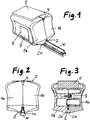
- FIG. 1 shows a perspective view of the Nachschneide réelle according to the invention, seen obliquely from the front, when cutting a wiper blade W.
- the Nachschneide réelle has a housing 1, which is composed of two lateral housing halves 1 a and 1 b along a plane extending in the longitudinal center plane separating plane. Through the out FIG. 1 clearly visible, slightly concave vaulted side surfaces of the housing 1, the recutting is very handy and therefore easy to handle.
- FIG. 2 shows a front view of the Nachschneide réelles with the wiper blade W, so that it can be seen how the guide slot 2 receives the wiper blade and engages with mutual guide rails 2a in the mutual transverse grooves of the wiper blade W.
- Fig. 3 shows a cross section through the Nachschneide réelle, also seen from the front, where the two housing halves 1a and 1b and their connection by screws 3 can be seen.
- a cleaning groove 4 is formed centrally in the front region of the regrooving device, and behind it a rectangular trough is formed in the upper side of the housing 1, in which a sponge 5 is inserted in a slightly clamping manner, so that it is easily removed can be. Before the regrooving of a wiper blade, it is pulled through the cleaning groove 4 in order to strip off dirt deposits from the wiper blade, and with the sponge 5, in particular, the base of the wiper blade can be cleaned.
- FIG. 5 shows a perspective cross-section through the Nachsteckide réelle shown upside down, and seen obliquely from behind, the cutting plane through the transverse shaft 6 and the therein, not shown cut knife block 7 can recognize.
- the sponge 5 located in an upper-side housing pan is thus at the bottom in this illustration, and the wiper blade W is at the top in the guide slot 2.
- the transversely displaceable knife block 7 is provided in the embodiment between two defined lateral positions. He therefore has on its underside, which is located in Figure 5 above, two parallel grooves 8, of which in one position of the knife block 7, a groove 8 and in the other position of the knife block 7, the other groove 8 is aligned with the guide slot 2 so that the wiper blade tip can dip into it.
- a knife blade 9 which is preferably connected to the knife block by ultrasonic welding, is arranged somewhat obliquely both with respect to the transverse direction and with respect to the height direction. Is the knife block 7 in its in FIG. 5 shown position, the cooperating with the wiper blade tip portion of the knife blade 9 is removed by a smaller distance from the guide rails of the guide slot 2, as in the shifted from this position slightly to the right other position of the knife block 7, where this distance is slightly larger.
- three different positions of the knife block 7 may be provided for a three times trimming.
- the knife block 7 is displaceable between two defined positions. To ensure a defined positioning in each of these two positions, the knife block has, as in FIG. 5 can be seen, two vertically extending notches 10 which cooperate with a locking lug or locking strip formed in the housing, so that the knife block 7 engages in each of the two possible positions.
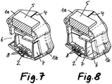
- FIGS. 6 and 7 show horizontal sections seen from below through the Nachschneide réelle, so looking at the bottom of the knife block 7, so that the grooves 8 in the knife block and arranged on the underside knife blade 9 are clearly visible.
- the show FIGS. 6 and 7 one and the other of the two possible positions of the knife block. 7
- FIGS. 8 and Fig. 9 show cross-sections of the regrooving device seen obliquely from behind, respectively FIG. 5 but not in the inverted position, but in the correct position of the Nachschneide réelles with the bottom guide slot 2, wherein in the FIGS. 8 and 9, the knife block is shown cut each.
- the knife block can also be arranged continuously displaceable in the transverse shaft 6, for example, in which a fixed in the knife block nut cooperates with a rotatable but axially fixed screw in the housing.
- a fixed in the knife block nut cooperates with a rotatable but axially fixed screw in the housing.
- other constructive variants of a stepped or continuous displaceability of the knife block in the transverse shaft can be provided.
Landscapes
- Life Sciences & Earth Sciences (AREA)
- Forests & Forestry (AREA)
- Engineering & Computer Science (AREA)
- Mechanical Engineering (AREA)
- Knives (AREA)
- Dicing (AREA)
Abstract
Description
- Die Erfindung betrifft ein Gerät zum Nachschneiden von Scheibenwischerblättern, wenn die Wischerblattkante veschlissen ist, um durch das Nachschneiden wieder eine saubere Wischerblattkante zu schaffen, die ein schlierenfreies Wischen von Autoscheiben ermöglichen.
- Aus dem
EP 2 580 032 B1 ist bereits ein Werkzeug zum Nachschneiden abgenutzter Wischerblätter für Scheibenwischer bekannt, das einen Führungsblock mit mindestens zwei parallelen und seitlich beabstandeten Führungsschlitzen aufweist, deren lichtes Querschnittprofil dem Querschnittprofil eines Wischerblatts entspricht, wobei die Führungsschlitze jeweils beiderseitige Führungsleisten aufweisen, die in die rückwärtigen beiderseitigen Quernuten des Wischerblatts eingreifen. Die Führungsleisten der mindestens zwei nebeneinander angeordneten Führungsschlitze haben einen unterschiedlichen Abstand zu einem im Profilspitzenbereich des Profilquerschnitts angeordneten Messerblatt, das zum Nachschneiden der Wischerkante dient, so dass ein Wischerblatt mindestens zweimal nachgeschnitten werden kann. - Aufgrund der Anordnung der Führungsschlitze nebeneinander ist der Führungsblock des Werkzeugs entsprechend breit und seine Führung entlang des Wischerblatts ist etwas schwierig, weil das Wischerblatt, wenn nicht gerade bei einer dem dortigen Ausführungsbeispiel entsprechenden Ausführungsform mit drei Führungsschlitzen der mittlere Führungsschlitz benutzt werden kann, das Wischerblatt sich stets außermittig zur Bewegungsachse des Werkzeugs befindet und deshalb wegen der außermittig wirkenden Schubkraft beim Schneiden stets eine Neigung zum Verkanten besteht.
- Aufgabe der Erfindung ist es, ein handlicheres, kleineres und das nachzuschneidende Wischerblatt stets mittig aufnehmendes Nachschneidegerät zu schaffen, das ebenfalls ein mindestens zweimaliges Nachschneiden des Wischerblatts ermöglicht.
- Diese Aufgabe wird erfindungsgemäß durch das im Anspruch 1 angegebene Nachschneidegerät gelöst. Vorteilhafte Ausgestaltungen der Erfindung sind Gegenstand der Unteransprüche.
- Das erfindungsgemäße Nachschneidegerät hat nur einen einzigen Führungsschlitz zur Aufnahme des Wischerblattprofils und kann damit insgesamt eine entsprechend geringe Breite haben. Das nachzuschneidende Wischerblatt befindet sich, quer zur Bewegungsrichtung beim Nachschneiden gesehen, stets mittig im Nachschneidegerät. Das Schneidmesser ist an einem im Gerät zwischen mindestens zwei Positionen quer verstellbaren Messerblock angeordnet, um dadurch zwischen mindestens zwei Positionen mit unterschiedlichem Abstand des Schneidmessers zu den Führungsleisten des Führungsschlitzes beim jeweiligen Schneidvorgang verstellbar zu sein. Vorzugsweise ist der Messerblock in den mindestens zwei vorgesehenen Positionen rastbar. Es kann aber auch eine stufenlose Einstellbarkeit beispielsweise mittels einer Stellschraube vorgesehen sein.
- Ein Ausführungsbeispiel der Erfindung wird nachstehend unter Bezugnahme auf die anliegenden Zeichnungen mehr im einzelnen beschrieben. In den Zeichnungen zeigt:
- Fig. 1
- das Nachschneidegerät in perspektivischer Ansicht von außen beim Schneiden eines Wischerblatts,
- Fig. 2
- eine Frontansicht des Nachschneidegeräts mit einem nachgeschnittenen Wischerblatt,
- Fig. 3
- einen Querschnitt durch das Nachschneidegerät ohne Wischerblatt,
- Fig. 4
- einen schräg von hinten gesehenen Querschnitt durch das Nachschneidegerät in kopfstehender Position,
- die Fig. 5 und 6
- Horizontalschnitte durch das Nachschneidegerät, von unten gesehen, wobei in
Fig. 5 der Messerblock sich in der einen und inFig. 6 in der anderen der beiden beim Ausführungsbeispiel vorgesehenen Schneidpositionen befindet, und - die Fig. 7 und 8
- perspektivische Querschnittedurch das Nachschneidegerät, jeweils von schräg hinten gesehen, wobei der ebenfalls geschnittene Messerblock wiederum in der einen bzw. in der anderen der beiden möglichen Positionen dargestellt ist.
-
Figur 1 zeigt in perspektivischer Ansicht das Nachschneidegerät nach der Erfindung, schräg von vorn gesehen, beim Schneiden eines Wischerblatts W. Das Nachschneidegerät hat ein Gehäuse 1, das aus zwei seitlichen Gehäusehälften 1a und 1b längs einer in der Längsmittelebene verlaufenden Trennebene zusammengesetzt ist. Durch die ausFigur 1 deutlich ersichtlichen, etwas konkav eingewölbten Seitenflächen des Gehäuses 1 ist das Nachschneidegerät sehr griffgünstig und damit handhabungsfreundlich. - Mittig unten im Gehäuse ist ein Führungsschlitz 2 gebildet, die dem Querschnittsprofil des Wischerblatts W angepasst ist. Man erkennt diesen Führungsschlitz 2 deutlicher in den
Figuren 2 und 3 , von denenFigur 2 eine Frontansicht des Nachschneidegeräts mit dem Wischerblatt W zeigt, so dass erkennbar ist, wie der Führungsschlitz 2 das Wischerblatt aufnimmt und mit beiderseitigen Führungsleisten 2a in die beiderseitigen Quernuten des Wischerblatts W eingreift.Fig. 3 zeigt einen Querschnitt durch das Nachschneidegerät, ebenfalls von vorn gesehen, wo die beiden Gehäusehälften 1a und 1b und deren Verbindung durch Schrauben 3 erkennbar sind. - Mittig oben ist im vorderen Bereich des Nachschneidegeräts eine Reinigungsnut 4 gebildet, und dahinter ist in der Oberseite des Gehäuses 1 eine rechteckige Wanne eingeformt, in der ein Schwamm 5 leicht klemmend eingesetzt ist, so dass er leicht herausgenommen werden kann. Vor dem Nachschneiden eines Wischerblatts wird dieses durch die Reinigungnsnut 4 hindurchgezogen, um Schmutzanhaftungen vom Wischerblatt abzustreifen, und mit dem Schwamm 5 kann insbesondere die Basis des Wischerblatts gesäubert werden.
- Weiter erkennt man in der perspektivischen Ansicht nach
Figur 1 einen Querschacht 6 im Gehäuse 1, in welchem ein Messerblock 7 quer verschiebbar angeordnet ist. -
Figur 5 zeigt einen perspektivischen Querschnitt durch das kopfstehend abgebildete Nachschneidegerät, und zwar schräg von hinten gesehen, wobei die Schnittebene durch den Querschacht 6 verläuft und den darin befindlichen, nicht geschnitten dargestellten Messerblock 7 erkennen lässt. Der in einer oberseitigen Gehäusewanne befindliche Schwamm 5 befindet sich in dieser Darstellung also unten, und das Wischerblatt W ist oben im Führungsschlitz 2. - Der quer verschiebbare Messerblock 7 ist beim Ausführungsbeispiel zwischen zwei definierten seitlichen Positionen vorgesehen. Er hat daher an seiner Unterseite, die sich in Figur 5 oben befindet, zwei parallele Nuten 8, von denen in der einen Position des Messerblocks 7 die eine Nut 8 und in der anderen Position des Messerblocks 7 die andere Nut 8 mit dem Führungsschlitz 2 fluchtet, so dass die Wischerblattspitze darin eintauchen kann.
- An der in
Figur 5 oben liegenden Unterseite des Messerblocks 7 ist sowohl bezüglich der Querrichtung als auch bezüglich der Höhenrichtung etwas schräg verlaufend ein Messerblatt 9 angeordnet, das vorzugsweise durch Ultraschallschweißung am Messerblock verbunden ist. Befindet sich der Messerblock 7 in seiner inFigur 5 dargestellten Position, ist der mit der Wischerblattspitze zusammenwirkende Schneidenbereich des Messerblatts 9 um eine geringere Distanz von den Führungsleisten des Führungsschlitzes 2 entfernt, als in der aus dieser Position etwas nach rechts verschobenen anderen Position des Messerblocks 7, wo diese Distanz etwas größer ist. Durch die in den beiden beim Ausführungsbeispiel vorgesehenen Messerblockpositionen ist also ein zweimaliges Nachschneiden eines Wischerblatts möglich. - Abweichend vom dargestellten Ausführungsbeispiel können auch drei verschiedene Positionen des Messerblocks 7 für ein dreimaliges Nachschneiden vorgesehen sein.
- Beim Ausführungsbeispiel ist vorgesehen, dass der Messerblock 7 zwischen zwei definierten Positionen verschiebbar ist. Um eine definierte Positionierung in jeder dieser beiden Positionen zu gewährleisten, hat der Messerblock, wie in
Figur 5 ersichtlich, zwei vertikal verlaufende Kerben 10, die mit einer im Gehäuse gebildeten Rastnase oder Rastleiste zusammenwirken, so dass der Messerblock 7 in jeder der beiden möglichen Positionen einrastet. - Die
Figuren 6 und7 zeigen von unten gesehene Horizontalschnitte durch das Nachschneidegerät, also mit Blick auf die Unterseite des Messerblocks 7, so dass die Nuten 8 im Messerblock und das an dessen Unterseite angeordnete Messerblatt 9 klar erkennbar sind. Dabei zeigen dieFiguren 6 und7 die eine und die andere der beiden möglichen Positionen des Messerblocks 7. - Die
Figuren 8 und 9 zeigen jeweils schräg von hinten gesehene Querschnitte des Nachschneidegeräts ähnlichFigur 5 , aber nicht in der kopfstehenden Position, sondern in der lagerichtigen Position des Nachschneidegeräts mit dem unten befindlichen Führungsschlitz 2, wobei in denFiguren 8 und 9 auch der Messerblock jeweils geschnitten dargestellt ist. - Abweichend vom dargestellten Ausführungsbeispiel mit rastbaren Positionen des Messerblocks kann der Messerblock auch stufenlos verschiebbar im Querschacht 6 angeordnet sein, beispielsweise in dem eine im Messerblock fixierte Schraubenmutter mit einer drehbar, aber axial festgelegten Schraube im Gehäuse zusammenwirkt. Es können darüber hinaus auch andere konstruktive Varianten einer stufigen oder stufenlosen Verschiebbarkeit des Messerblocks im Querschacht vorgesehen sein.
Claims (7)
- Nachschneidegerät für Scheibenwischerblätter mit einem dem Querschnitsprofil des Wischerblatts (W) angepassten Führungsschlitz (2) mit Führungsleisten (2a), die in seitliche Nuten der Wischerblattbasis eingreifen, und mit einem in definiertem Abstand zu den Führungsleisten gehaltenen Schneidmesser (9) zum Nachschneiden der Wischerblattkante,
dadurch gekennzeichnet, dass das Schneidmesser (9) in schräger Position an einem Messerblock (7) angeordnet ist, der in einem Gehäuse (1) zwischen mindestens zwei Positionen quer verschiebbar ist, wobei in den mindestens zwei Positionen der Abstand zwischen den Führungsleisten (2a) und dem jeweils im Führungsschlitzbereich befindlichen Schneidenbereich des Schneidmessers (9) unterschiedlich groß ist. - Nachschneidegerät nach Anspruch 1, wobei der Messerblock (7) in einem Querschacht (6) des Gehäuses (1) verschiebbar ist.
- Nachschneidegerät nach Anspruch 1 oder 2, wobei der Messerblock (7) in seinen mindestens zwei Positionen rastbar ist.
- Nachschneidegerät nach Anspruch 1 oder 2, wobei der Messerblock (7) mittels eines Schraubspindeltriebs stufenlos quer verschiebbar im Gehäuse (1) angeordnet ist.
- Nachschneidegerät nach einem der Ansprüche 1 bis 4, wobei im Gehäuse (1) zusätzlich zum Führungsschlitz (2) ein Reinigungsschlitz (4) gebildet ist, durch welchen das Wischerblatt (W) zum Abstreifen von Schmutzanhaftungen hindurchgeführt werden kann.
- Nachschneidegerät nach Anspruch 5, wobei der Reinigungsschlitz (4) gegenüber dem Führungsschlitz (2) an der Gehäuseoberseite angeordnet ist.
- Nachschneidegerät nach einem der Ansprüche 1 bis 6, wobei an der Gehäuseoberseite eine Mulde zum Einsetzen eines Schwämmchens (5) gebildet ist.
Applications Claiming Priority (1)
| Application Number | Priority Date | Filing Date | Title |
|---|---|---|---|
| DE202017002690.2U DE202017002690U1 (de) | 2017-05-19 | 2017-05-19 | Scheibenwischerblatt-Nachschneidegerät |
Publications (2)
| Publication Number | Publication Date |
|---|---|
| EP3403776A1 true EP3403776A1 (de) | 2018-11-21 |
| EP3403776B1 EP3403776B1 (de) | 2023-01-18 |
Family
ID=59580538
Family Applications (1)
| Application Number | Title | Priority Date | Filing Date |
|---|---|---|---|
| EP17001708.1A Active EP3403776B1 (de) | 2017-05-19 | 2017-10-17 | Scheibenwischerblatt-nachschneidegerät |
Country Status (3)
| Country | Link |
|---|---|
| US (1) | US20180333883A1 (de) |
| EP (1) | EP3403776B1 (de) |
| DE (1) | DE202017002690U1 (de) |
Families Citing this family (4)
| Publication number | Priority date | Publication date | Assignee | Title |
|---|---|---|---|---|
| LU100917B1 (de) * | 2018-08-29 | 2020-03-03 | Genius Gmbh | Werkzeug |
| DE202018104991U1 (de) | 2018-08-31 | 2018-09-20 | Aspiria Nonfood Gmbh | Werkzeug zum Nachschneiden abgenutzter Wischerblätter für Scheibenwischer |
| US11318634B2 (en) * | 2019-05-20 | 2022-05-03 | Joel Dollar | Windshield wiper cutter |
| CN114084099B (zh) * | 2022-01-17 | 2022-05-10 | 宁波市法莱欣科技有限公司 | 一种雨刮器 |
Citations (4)
| Publication number | Priority date | Publication date | Assignee | Title |
|---|---|---|---|---|
| US5123764A (en) * | 1990-05-23 | 1992-06-23 | Duncan Marvin G | Utility cleaning tool for windshield wiper blades |
| US5848471A (en) * | 1996-07-03 | 1998-12-15 | Freeland; Jay | Windshield wiper reconditioning device |
| JP2006174980A (ja) * | 2004-12-22 | 2006-07-06 | Masafumi Tamagawa | ワイパーブレード再生用カッター |
| EP2580032B1 (de) | 2010-06-11 | 2016-05-04 | Mario Kronberg | Werkzeug zum nachschneiden von wischerblättern |
Family Cites Families (1)
| Publication number | Priority date | Publication date | Assignee | Title |
|---|---|---|---|---|
| DE10243690B4 (de) * | 2002-09-20 | 2006-09-14 | Martin Sieke | Anordnung zum Nachschneiden von Scheibenwischerblättern |
-
2017
- 2017-05-19 DE DE202017002690.2U patent/DE202017002690U1/de active Active
- 2017-10-17 EP EP17001708.1A patent/EP3403776B1/de active Active
- 2017-11-02 US US15/801,660 patent/US20180333883A1/en not_active Abandoned
Patent Citations (4)
| Publication number | Priority date | Publication date | Assignee | Title |
|---|---|---|---|---|
| US5123764A (en) * | 1990-05-23 | 1992-06-23 | Duncan Marvin G | Utility cleaning tool for windshield wiper blades |
| US5848471A (en) * | 1996-07-03 | 1998-12-15 | Freeland; Jay | Windshield wiper reconditioning device |
| JP2006174980A (ja) * | 2004-12-22 | 2006-07-06 | Masafumi Tamagawa | ワイパーブレード再生用カッター |
| EP2580032B1 (de) | 2010-06-11 | 2016-05-04 | Mario Kronberg | Werkzeug zum nachschneiden von wischerblättern |
Also Published As
| Publication number | Publication date |
|---|---|
| EP3403776B1 (de) | 2023-01-18 |
| US20180333883A1 (en) | 2018-11-22 |
| DE202017002690U1 (de) | 2017-07-21 |
Similar Documents
| Publication | Publication Date | Title |
|---|---|---|
| EP2580032B1 (de) | Werkzeug zum nachschneiden von wischerblättern | |
| EP3403776A1 (de) | Scheibenwischerblatt-nachschneidegerät | |
| DE9210045U1 (de) | Rasierapparatekopf mit Durchflußöffnungen | |
| DE10054174A1 (de) | Küchengerät zum Schneiden von Schneidgut | |
| DE2231517A1 (de) | Stanzvorrichtung zum lochen der wand von rohren | |
| DE2542346A1 (de) | Innenraeumwerkzeug, insbesondere zur herstellung von profilnuten | |
| EP3626317A1 (de) | Tor | |
| DE29500422U1 (de) | Chirurgisches Stanzwerkzeug | |
| EP1245352A1 (de) | Manuell bewegbarer Gurthobel | |
| DE102015204325A1 (de) | Kantenfräsgruppe für die Bearbeitung von Paneelen aus Holz oder Ähnlichem | |
| EP1377198A1 (de) | Eiskratzer | |
| DE2853376A1 (de) | Doppelklingen-rasierapparat mit einem reinigungsmechanismus | |
| DE102019116772A1 (de) | Verfahren zum Herstellen von Scheren und Kombination aus mindestens zwei Scheren | |
| EP2152550B1 (de) | Wischleiste und verfahren zu ihrer herstellung | |
| DE102013019598B4 (de) | Verfahren und Vorrichtung zur Herstellung von Aussparungen in Haltestangen | |
| DE975208C (de) | Vorrichtung zum gleichzeitigen Beschneiden beider Kanten der Wischlippe von Wischblaettern | |
| DE102008010444B4 (de) | Schneidsatz für eine Haarschneidemaschine | |
| DE1002659B (de) | Elektrisch angetriebene Haarschneidemaschine oder elektrisch angetriebener Rasierapparat | |
| DE458914C (de) | Glaszuschneide-Lineal | |
| EP0628386B1 (de) | Gemüsehobel | |
| LU100917B1 (de) | Werkzeug | |
| DE3420252A1 (de) | Haarschneidemaschine | |
| DE20007691U1 (de) | Messerbehandlungsgerät | |
| DE10257553A1 (de) | Wischblatt | |
| DE9405275U1 (de) | Schneidvorrichtung |
Legal Events
| Date | Code | Title | Description |
|---|---|---|---|
| PUAI | Public reference made under article 153(3) epc to a published international application that has entered the european phase |
Free format text: ORIGINAL CODE: 0009012 |
|
| STAA | Information on the status of an ep patent application or granted ep patent |
Free format text: STATUS: THE APPLICATION HAS BEEN PUBLISHED |
|
| AK | Designated contracting states |
Kind code of ref document: A1 Designated state(s): AL AT BE BG CH CY CZ DE DK EE ES FI FR GB GR HR HU IE IS IT LI LT LU LV MC MK MT NL NO PL PT RO RS SE SI SK SM TR |
|
| AX | Request for extension of the european patent |
Extension state: BA ME |
|
| STAA | Information on the status of an ep patent application or granted ep patent |
Free format text: STATUS: REQUEST FOR EXAMINATION WAS MADE |
|
| 17P | Request for examination filed |
Effective date: 20181219 |
|
| RBV | Designated contracting states (corrected) |
Designated state(s): AL AT BE BG CH CY CZ DE DK EE ES FI FR GB GR HR HU IE IS IT LI LT LU LV MC MK MT NL NO PL PT RO RS SE SI SK SM TR |
|
| STAA | Information on the status of an ep patent application or granted ep patent |
Free format text: STATUS: EXAMINATION IS IN PROGRESS |
|
| 17Q | First examination report despatched |
Effective date: 20210924 |
|
| GRAP | Despatch of communication of intention to grant a patent |
Free format text: ORIGINAL CODE: EPIDOSNIGR1 |
|
| STAA | Information on the status of an ep patent application or granted ep patent |
Free format text: STATUS: GRANT OF PATENT IS INTENDED |
|
| RIC1 | Information provided on ipc code assigned before grant |
Ipc: B26D 7/01 20060101ALI20221018BHEP Ipc: B26D 3/28 20060101ALI20221018BHEP Ipc: B26B 27/00 20060101ALI20221018BHEP Ipc: B26B 29/00 20060101ALI20221018BHEP Ipc: B26D 1/02 20060101ALI20221018BHEP Ipc: B26D 3/00 20060101ALI20221018BHEP Ipc: B26D 7/08 20060101ALI20221018BHEP Ipc: B26D 7/26 20060101ALI20221018BHEP Ipc: B60S 1/38 20060101ALI20221018BHEP Ipc: B26B 1/08 20060101AFI20221018BHEP |
|
| GRAS | Grant fee paid |
Free format text: ORIGINAL CODE: EPIDOSNIGR3 |
|
| INTG | Intention to grant announced |
Effective date: 20221111 |
|
| GRAA | (expected) grant |
Free format text: ORIGINAL CODE: 0009210 |
|
| STAA | Information on the status of an ep patent application or granted ep patent |
Free format text: STATUS: THE PATENT HAS BEEN GRANTED |
|
| AK | Designated contracting states |
Kind code of ref document: B1 Designated state(s): AL AT BE BG CH CY CZ DE DK EE ES FI FR GB GR HR HU IE IS IT LI LT LU LV MC MK MT NL NO PL PT RO RS SE SI SK SM TR |
|
| REG | Reference to a national code |
Ref country code: GB Ref legal event code: FG4D Free format text: NOT ENGLISH |
|
| REG | Reference to a national code |
Ref country code: DE Ref legal event code: R096 Ref document number: 502017014333 Country of ref document: DE |
|
| REG | Reference to a national code |
Ref country code: CH Ref legal event code: EP |
|
| REG | Reference to a national code |
Ref country code: AT Ref legal event code: REF Ref document number: 1544428 Country of ref document: AT Kind code of ref document: T Effective date: 20230215 Ref country code: IE Ref legal event code: FG4D Free format text: LANGUAGE OF EP DOCUMENT: GERMAN |
|
| REG | Reference to a national code |
Ref country code: LT Ref legal event code: MG9D |
|
| REG | Reference to a national code |
Ref country code: NL Ref legal event code: MP Effective date: 20230118 |
|
| PG25 | Lapsed in a contracting state [announced via postgrant information from national office to epo] |
Ref country code: NL Free format text: LAPSE BECAUSE OF FAILURE TO SUBMIT A TRANSLATION OF THE DESCRIPTION OR TO PAY THE FEE WITHIN THE PRESCRIBED TIME-LIMIT Effective date: 20230118 |
|
| PG25 | Lapsed in a contracting state [announced via postgrant information from national office to epo] |
Ref country code: RS Free format text: LAPSE BECAUSE OF FAILURE TO SUBMIT A TRANSLATION OF THE DESCRIPTION OR TO PAY THE FEE WITHIN THE PRESCRIBED TIME-LIMIT Effective date: 20230118 Ref country code: PT Free format text: LAPSE BECAUSE OF FAILURE TO SUBMIT A TRANSLATION OF THE DESCRIPTION OR TO PAY THE FEE WITHIN THE PRESCRIBED TIME-LIMIT Effective date: 20230518 Ref country code: NO Free format text: LAPSE BECAUSE OF FAILURE TO SUBMIT A TRANSLATION OF THE DESCRIPTION OR TO PAY THE FEE WITHIN THE PRESCRIBED TIME-LIMIT Effective date: 20230418 Ref country code: LV Free format text: LAPSE BECAUSE OF FAILURE TO SUBMIT A TRANSLATION OF THE DESCRIPTION OR TO PAY THE FEE WITHIN THE PRESCRIBED TIME-LIMIT Effective date: 20230118 Ref country code: LT Free format text: LAPSE BECAUSE OF FAILURE TO SUBMIT A TRANSLATION OF THE DESCRIPTION OR TO PAY THE FEE WITHIN THE PRESCRIBED TIME-LIMIT Effective date: 20230118 Ref country code: HR Free format text: LAPSE BECAUSE OF FAILURE TO SUBMIT A TRANSLATION OF THE DESCRIPTION OR TO PAY THE FEE WITHIN THE PRESCRIBED TIME-LIMIT Effective date: 20230118 Ref country code: ES Free format text: LAPSE BECAUSE OF FAILURE TO SUBMIT A TRANSLATION OF THE DESCRIPTION OR TO PAY THE FEE WITHIN THE PRESCRIBED TIME-LIMIT Effective date: 20230118 |
|
| PG25 | Lapsed in a contracting state [announced via postgrant information from national office to epo] |
Ref country code: SE Free format text: LAPSE BECAUSE OF FAILURE TO SUBMIT A TRANSLATION OF THE DESCRIPTION OR TO PAY THE FEE WITHIN THE PRESCRIBED TIME-LIMIT Effective date: 20230118 Ref country code: PL Free format text: LAPSE BECAUSE OF FAILURE TO SUBMIT A TRANSLATION OF THE DESCRIPTION OR TO PAY THE FEE WITHIN THE PRESCRIBED TIME-LIMIT Effective date: 20230118 Ref country code: IS Free format text: LAPSE BECAUSE OF FAILURE TO SUBMIT A TRANSLATION OF THE DESCRIPTION OR TO PAY THE FEE WITHIN THE PRESCRIBED TIME-LIMIT Effective date: 20230518 Ref country code: GR Free format text: LAPSE BECAUSE OF FAILURE TO SUBMIT A TRANSLATION OF THE DESCRIPTION OR TO PAY THE FEE WITHIN THE PRESCRIBED TIME-LIMIT Effective date: 20230419 Ref country code: FI Free format text: LAPSE BECAUSE OF FAILURE TO SUBMIT A TRANSLATION OF THE DESCRIPTION OR TO PAY THE FEE WITHIN THE PRESCRIBED TIME-LIMIT Effective date: 20230118 |
|
| REG | Reference to a national code |
Ref country code: DE Ref legal event code: R097 Ref document number: 502017014333 Country of ref document: DE |
|
| PG25 | Lapsed in a contracting state [announced via postgrant information from national office to epo] |
Ref country code: SM Free format text: LAPSE BECAUSE OF FAILURE TO SUBMIT A TRANSLATION OF THE DESCRIPTION OR TO PAY THE FEE WITHIN THE PRESCRIBED TIME-LIMIT Effective date: 20230118 Ref country code: RO Free format text: LAPSE BECAUSE OF FAILURE TO SUBMIT A TRANSLATION OF THE DESCRIPTION OR TO PAY THE FEE WITHIN THE PRESCRIBED TIME-LIMIT Effective date: 20230118 Ref country code: EE Free format text: LAPSE BECAUSE OF FAILURE TO SUBMIT A TRANSLATION OF THE DESCRIPTION OR TO PAY THE FEE WITHIN THE PRESCRIBED TIME-LIMIT Effective date: 20230118 Ref country code: DK Free format text: LAPSE BECAUSE OF FAILURE TO SUBMIT A TRANSLATION OF THE DESCRIPTION OR TO PAY THE FEE WITHIN THE PRESCRIBED TIME-LIMIT Effective date: 20230118 Ref country code: CZ Free format text: LAPSE BECAUSE OF FAILURE TO SUBMIT A TRANSLATION OF THE DESCRIPTION OR TO PAY THE FEE WITHIN THE PRESCRIBED TIME-LIMIT Effective date: 20230118 |
|
| PLBE | No opposition filed within time limit |
Free format text: ORIGINAL CODE: 0009261 |
|
| STAA | Information on the status of an ep patent application or granted ep patent |
Free format text: STATUS: NO OPPOSITION FILED WITHIN TIME LIMIT |
|
| PG25 | Lapsed in a contracting state [announced via postgrant information from national office to epo] |
Ref country code: SK Free format text: LAPSE BECAUSE OF FAILURE TO SUBMIT A TRANSLATION OF THE DESCRIPTION OR TO PAY THE FEE WITHIN THE PRESCRIBED TIME-LIMIT Effective date: 20230118 |
|
| 26N | No opposition filed |
Effective date: 20231019 |
|
| PG25 | Lapsed in a contracting state [announced via postgrant information from national office to epo] |
Ref country code: SI Free format text: LAPSE BECAUSE OF FAILURE TO SUBMIT A TRANSLATION OF THE DESCRIPTION OR TO PAY THE FEE WITHIN THE PRESCRIBED TIME-LIMIT Effective date: 20230118 |
|
| PGFP | Annual fee paid to national office [announced via postgrant information from national office to epo] |
Ref country code: CH Payment date: 20231102 Year of fee payment: 7 Ref country code: AT Payment date: 20231019 Year of fee payment: 7 |
|
| PG25 | Lapsed in a contracting state [announced via postgrant information from national office to epo] |
Ref country code: IT Free format text: LAPSE BECAUSE OF FAILURE TO SUBMIT A TRANSLATION OF THE DESCRIPTION OR TO PAY THE FEE WITHIN THE PRESCRIBED TIME-LIMIT Effective date: 20230118 Ref country code: MC Free format text: LAPSE BECAUSE OF FAILURE TO SUBMIT A TRANSLATION OF THE DESCRIPTION OR TO PAY THE FEE WITHIN THE PRESCRIBED TIME-LIMIT Effective date: 20230118 |
|
| REG | Reference to a national code |
Ref country code: BE Ref legal event code: MM Effective date: 20231031 |
|
| PG25 | Lapsed in a contracting state [announced via postgrant information from national office to epo] |
Ref country code: LU Free format text: LAPSE BECAUSE OF NON-PAYMENT OF DUE FEES Effective date: 20231017 |
|
| GBPC | Gb: european patent ceased through non-payment of renewal fee |
Effective date: 20231017 |
|
| PG25 | Lapsed in a contracting state [announced via postgrant information from national office to epo] |
Ref country code: LU Free format text: LAPSE BECAUSE OF NON-PAYMENT OF DUE FEES Effective date: 20231017 |
|
| PG25 | Lapsed in a contracting state [announced via postgrant information from national office to epo] |
Ref country code: GB Free format text: LAPSE BECAUSE OF NON-PAYMENT OF DUE FEES Effective date: 20231017 |
|
| PG25 | Lapsed in a contracting state [announced via postgrant information from national office to epo] |
Ref country code: GB Free format text: LAPSE BECAUSE OF NON-PAYMENT OF DUE FEES Effective date: 20231017 Ref country code: FR Free format text: LAPSE BECAUSE OF NON-PAYMENT OF DUE FEES Effective date: 20231031 |
|
| PG25 | Lapsed in a contracting state [announced via postgrant information from national office to epo] |
Ref country code: BE Free format text: LAPSE BECAUSE OF NON-PAYMENT OF DUE FEES Effective date: 20231031 |
|
| PG25 | Lapsed in a contracting state [announced via postgrant information from national office to epo] |
Ref country code: IE Free format text: LAPSE BECAUSE OF NON-PAYMENT OF DUE FEES Effective date: 20231017 |
|
| PG25 | Lapsed in a contracting state [announced via postgrant information from national office to epo] |
Ref country code: IE Free format text: LAPSE BECAUSE OF NON-PAYMENT OF DUE FEES Effective date: 20231017 |
|
| PG25 | Lapsed in a contracting state [announced via postgrant information from national office to epo] |
Ref country code: BG Free format text: LAPSE BECAUSE OF FAILURE TO SUBMIT A TRANSLATION OF THE DESCRIPTION OR TO PAY THE FEE WITHIN THE PRESCRIBED TIME-LIMIT Effective date: 20230118 |
|
| PG25 | Lapsed in a contracting state [announced via postgrant information from national office to epo] |
Ref country code: BG Free format text: LAPSE BECAUSE OF FAILURE TO SUBMIT A TRANSLATION OF THE DESCRIPTION OR TO PAY THE FEE WITHIN THE PRESCRIBED TIME-LIMIT Effective date: 20230118 |
|
| REG | Reference to a national code |
Ref country code: CH Ref legal event code: PL |
|
| REG | Reference to a national code |
Ref country code: AT Ref legal event code: MM01 Ref document number: 1544428 Country of ref document: AT Kind code of ref document: T Effective date: 20241017 |
|
| PG25 | Lapsed in a contracting state [announced via postgrant information from national office to epo] |
Ref country code: CH Free format text: LAPSE BECAUSE OF NON-PAYMENT OF DUE FEES Effective date: 20241031 |
|
| PG25 | Lapsed in a contracting state [announced via postgrant information from national office to epo] |
Ref country code: AT Free format text: LAPSE BECAUSE OF NON-PAYMENT OF DUE FEES Effective date: 20241017 |
|
| PG25 | Lapsed in a contracting state [announced via postgrant information from national office to epo] |
Ref country code: CY Free format text: LAPSE BECAUSE OF FAILURE TO SUBMIT A TRANSLATION OF THE DESCRIPTION OR TO PAY THE FEE WITHIN THE PRESCRIBED TIME-LIMIT; INVALID AB INITIO Effective date: 20171017 |
|
| PG25 | Lapsed in a contracting state [announced via postgrant information from national office to epo] |
Ref country code: HU Free format text: LAPSE BECAUSE OF FAILURE TO SUBMIT A TRANSLATION OF THE DESCRIPTION OR TO PAY THE FEE WITHIN THE PRESCRIBED TIME-LIMIT; INVALID AB INITIO Effective date: 20171017 |
|
| PG25 | Lapsed in a contracting state [announced via postgrant information from national office to epo] |
Ref country code: TR Free format text: LAPSE BECAUSE OF FAILURE TO SUBMIT A TRANSLATION OF THE DESCRIPTION OR TO PAY THE FEE WITHIN THE PRESCRIBED TIME-LIMIT Effective date: 20230118 |
|
| PGFP | Annual fee paid to national office [announced via postgrant information from national office to epo] |
Ref country code: DE Payment date: 20251016 Year of fee payment: 9 |