EP3404247A1 - Abgaswärmetauscher mit gestapelten flachrohren - Google Patents
Abgaswärmetauscher mit gestapelten flachrohren Download PDFInfo
- Publication number
- EP3404247A1 EP3404247A1 EP17738584.6A EP17738584A EP3404247A1 EP 3404247 A1 EP3404247 A1 EP 3404247A1 EP 17738584 A EP17738584 A EP 17738584A EP 3404247 A1 EP3404247 A1 EP 3404247A1
- Authority
- EP
- European Patent Office
- Prior art keywords
- cooling water
- stacked
- exhaust gas
- case
- tube body
- Prior art date
- Legal status (The legal status is an assumption and is not a legal conclusion. Google has not performed a legal analysis and makes no representation as to the accuracy of the status listed.)
- Granted
Links
Images


Classifications
-
- F—MECHANICAL ENGINEERING; LIGHTING; HEATING; WEAPONS; BLASTING
- F02—COMBUSTION ENGINES; HOT-GAS OR COMBUSTION-PRODUCT ENGINE PLANTS
- F02M—SUPPLYING COMBUSTION ENGINES IN GENERAL WITH COMBUSTIBLE MIXTURES OR CONSTITUENTS THEREOF
- F02M26/00—Engine-pertinent apparatus for adding exhaust gases to combustion-air, main fuel or fuel-air mixture, e.g. by exhaust gas recirculation [EGR] systems
- F02M26/13—Arrangement or layout of EGR passages, e.g. in relation to specific engine parts or for incorporation of accessories
- F02M26/22—Arrangement or layout of EGR passages, e.g. in relation to specific engine parts or for incorporation of accessories with coolers in the recirculation passage
- F02M26/29—Constructional details of the coolers, e.g. pipes, plates, ribs, insulation or materials
- F02M26/32—Liquid-cooled heat exchangers
-
- F—MECHANICAL ENGINEERING; LIGHTING; HEATING; WEAPONS; BLASTING
- F28—HEAT EXCHANGE IN GENERAL
- F28D—HEAT-EXCHANGE APPARATUS, NOT PROVIDED FOR IN ANOTHER SUBCLASS, IN WHICH THE HEAT-EXCHANGE MEDIA DO NOT COME INTO DIRECT CONTACT
- F28D1/00—Heat-exchange apparatus having stationary conduit assemblies for one heat-exchange medium only, the media being in contact with different sides of the conduit wall, in which the other heat-exchange medium is a large body of fluid, e.g. domestic or motor car radiators
- F28D1/02—Heat-exchange apparatus having stationary conduit assemblies for one heat-exchange medium only, the media being in contact with different sides of the conduit wall, in which the other heat-exchange medium is a large body of fluid, e.g. domestic or motor car radiators with heat-exchange conduits immersed in the body of fluid
- F28D1/04—Heat-exchange apparatus having stationary conduit assemblies for one heat-exchange medium only, the media being in contact with different sides of the conduit wall, in which the other heat-exchange medium is a large body of fluid, e.g. domestic or motor car radiators with heat-exchange conduits immersed in the body of fluid with tubular conduits
- F28D1/053—Heat-exchange apparatus having stationary conduit assemblies for one heat-exchange medium only, the media being in contact with different sides of the conduit wall, in which the other heat-exchange medium is a large body of fluid, e.g. domestic or motor car radiators with heat-exchange conduits immersed in the body of fluid with tubular conduits the conduits being straight
-
- F—MECHANICAL ENGINEERING; LIGHTING; HEATING; WEAPONS; BLASTING
- F28—HEAT EXCHANGE IN GENERAL
- F28D—HEAT-EXCHANGE APPARATUS, NOT PROVIDED FOR IN ANOTHER SUBCLASS, IN WHICH THE HEAT-EXCHANGE MEDIA DO NOT COME INTO DIRECT CONTACT
- F28D21/00—Heat-exchange apparatus not covered by any of the groups F28D1/00 - F28D20/00
- F28D21/0001—Recuperative heat exchangers
- F28D21/0003—Recuperative heat exchangers the heat being recuperated from exhaust gases
-
- F—MECHANICAL ENGINEERING; LIGHTING; HEATING; WEAPONS; BLASTING
- F28—HEAT EXCHANGE IN GENERAL
- F28D—HEAT-EXCHANGE APPARATUS, NOT PROVIDED FOR IN ANOTHER SUBCLASS, IN WHICH THE HEAT-EXCHANGE MEDIA DO NOT COME INTO DIRECT CONTACT
- F28D7/00—Heat-exchange apparatus having stationary tubular conduit assemblies for both heat-exchange media, the media being in contact with different sides of a conduit wall
- F28D7/0066—Multi-circuit heat-exchangers, e.g. integrating different heat exchange sections in the same unit or heat-exchangers for more than two fluids
- F28D7/0075—Multi-circuit heat-exchangers, e.g. integrating different heat exchange sections in the same unit or heat-exchangers for more than two fluids with particular circuits for the same heat exchange medium, e.g. with the same heat exchange medium flowing through sections having different heat exchange capacities or for heating or cooling the same heat exchange medium at different temperatures
-
- F—MECHANICAL ENGINEERING; LIGHTING; HEATING; WEAPONS; BLASTING
- F28—HEAT EXCHANGE IN GENERAL
- F28D—HEAT-EXCHANGE APPARATUS, NOT PROVIDED FOR IN ANOTHER SUBCLASS, IN WHICH THE HEAT-EXCHANGE MEDIA DO NOT COME INTO DIRECT CONTACT
- F28D7/00—Heat-exchange apparatus having stationary tubular conduit assemblies for both heat-exchange media, the media being in contact with different sides of a conduit wall
- F28D7/16—Heat-exchange apparatus having stationary tubular conduit assemblies for both heat-exchange media, the media being in contact with different sides of a conduit wall the conduits being arranged in parallel spaced relation
- F28D7/1684—Heat-exchange apparatus having stationary tubular conduit assemblies for both heat-exchange media, the media being in contact with different sides of a conduit wall the conduits being arranged in parallel spaced relation the conduits having a non-circular cross-section
-
- F—MECHANICAL ENGINEERING; LIGHTING; HEATING; WEAPONS; BLASTING
- F28—HEAT EXCHANGE IN GENERAL
- F28F—DETAILS OF HEAT-EXCHANGE AND HEAT-TRANSFER APPARATUS, OF GENERAL APPLICATION
- F28F1/00—Tubular elements; Assemblies of tubular elements
- F28F1/02—Tubular elements of cross-section which is non-circular
- F28F1/022—Tubular elements of cross-section which is non-circular with multiple channels
-
- F—MECHANICAL ENGINEERING; LIGHTING; HEATING; WEAPONS; BLASTING
- F28—HEAT EXCHANGE IN GENERAL
- F28F—DETAILS OF HEAT-EXCHANGE AND HEAT-TRANSFER APPARATUS, OF GENERAL APPLICATION
- F28F1/00—Tubular elements; Assemblies of tubular elements
- F28F1/02—Tubular elements of cross-section which is non-circular
- F28F1/025—Tubular elements of cross-section which is non-circular with variable shape, e.g. with modified tube ends, with different geometrical features
-
- F—MECHANICAL ENGINEERING; LIGHTING; HEATING; WEAPONS; BLASTING
- F28—HEAT EXCHANGE IN GENERAL
- F28F—DETAILS OF HEAT-EXCHANGE AND HEAT-TRANSFER APPARATUS, OF GENERAL APPLICATION
- F28F9/00—Casings; Header boxes; Auxiliary supports for elements; Auxiliary members within casings
- F28F9/001—Casings in the form of plate-like arrangements; Frames enclosing a heat exchange core
-
- F—MECHANICAL ENGINEERING; LIGHTING; HEATING; WEAPONS; BLASTING
- F28—HEAT EXCHANGE IN GENERAL
- F28F—DETAILS OF HEAT-EXCHANGE AND HEAT-TRANSFER APPARATUS, OF GENERAL APPLICATION
- F28F9/00—Casings; Header boxes; Auxiliary supports for elements; Auxiliary members within casings
- F28F9/02—Header boxes; End plates
- F28F9/026—Header boxes; End plates with static flow control means, e.g. with means for uniformly distributing heat exchange media into conduits
- F28F9/0265—Header boxes; End plates with static flow control means, e.g. with means for uniformly distributing heat exchange media into conduits by using guiding means or impingement means inside the header box
-
- F—MECHANICAL ENGINEERING; LIGHTING; HEATING; WEAPONS; BLASTING
- F28—HEAT EXCHANGE IN GENERAL
- F28F—DETAILS OF HEAT-EXCHANGE AND HEAT-TRANSFER APPARATUS, OF GENERAL APPLICATION
- F28F9/00—Casings; Header boxes; Auxiliary supports for elements; Auxiliary members within casings
- F28F9/02—Header boxes; End plates
- F28F9/026—Header boxes; End plates with static flow control means, e.g. with means for uniformly distributing heat exchange media into conduits
- F28F9/0278—Header boxes; End plates with static flow control means, e.g. with means for uniformly distributing heat exchange media into conduits in the form of stacked distribution plates or perforated plates arranged over end plates
-
- F—MECHANICAL ENGINEERING; LIGHTING; HEATING; WEAPONS; BLASTING
- F28—HEAT EXCHANGE IN GENERAL
- F28F—DETAILS OF HEAT-EXCHANGE AND HEAT-TRANSFER APPARATUS, OF GENERAL APPLICATION
- F28F9/00—Casings; Header boxes; Auxiliary supports for elements; Auxiliary members within casings
- F28F9/22—Arrangements for directing heat-exchange media into successive compartments, e.g. arrangements of guide plates
-
- F—MECHANICAL ENGINEERING; LIGHTING; HEATING; WEAPONS; BLASTING
- F01—MACHINES OR ENGINES IN GENERAL; ENGINE PLANTS IN GENERAL; STEAM ENGINES
- F01N—GAS-FLOW SILENCERS OR EXHAUST APPARATUS FOR MACHINES OR ENGINES IN GENERAL; GAS-FLOW SILENCERS OR EXHAUST APPARATUS FOR INTERNAL-COMBUSTION ENGINES
- F01N5/00—Exhaust or silencing apparatus combined or associated with devices profiting by exhaust energy
- F01N5/02—Exhaust or silencing apparatus combined or associated with devices profiting by exhaust energy the devices using heat
-
- F—MECHANICAL ENGINEERING; LIGHTING; HEATING; WEAPONS; BLASTING
- F28—HEAT EXCHANGE IN GENERAL
- F28D—HEAT-EXCHANGE APPARATUS, NOT PROVIDED FOR IN ANOTHER SUBCLASS, IN WHICH THE HEAT-EXCHANGE MEDIA DO NOT COME INTO DIRECT CONTACT
- F28D21/00—Heat-exchange apparatus not covered by any of the groups F28D1/00 - F28D20/00
- F28D2021/0019—Other heat exchangers for particular applications; Heat exchange systems not otherwise provided for
- F28D2021/008—Other heat exchangers for particular applications; Heat exchange systems not otherwise provided for for vehicles
-
- F—MECHANICAL ENGINEERING; LIGHTING; HEATING; WEAPONS; BLASTING
- F28—HEAT EXCHANGE IN GENERAL
- F28F—DETAILS OF HEAT-EXCHANGE AND HEAT-TRANSFER APPARATUS, OF GENERAL APPLICATION
- F28F1/00—Tubular elements; Assemblies of tubular elements
- F28F1/02—Tubular elements of cross-section which is non-circular
- F28F2001/027—Tubular elements of cross-section which is non-circular with dimples
Definitions
- the present invention relates to an exhaust gas heat exchanger having stacked flat tubes such as an EGR cooler, in which boiling of cooling water inside a case is suppressed.
- an EGR (Exhaust Gas Recirculation) device In order to reduce nitrogen oxide (NOx) contained in exhaust gas exhausted from an engine of a vehicle or the like, or to reduce pumping loss, to mount an EGR (Exhaust Gas Recirculation) device on a vehicle is generally performed.
- an EGR cooler which is a kind of an exhaust gas heat exchanger and for cooling the exhaust gas, is provided, in a line through which a part of the exhaust gas is recirculated to an intake side of the engine.
- a general EGR cooler includes a stacked tube body arranged inside a case; the cooler configured such that exhaust gas flows in from one end part of a stacked tube body in a tube axis direction to circulate through the inside of respective flat tubes and flow out from the other end part; and cooling water introduced from a cooling water introduction part provided for the case is supplied to the above-described one end part and circulates through an outer surface side of respective flat tubes.
- exhaust gas having flowed in from one end part of the stacked tube body in the tube axis direction is cooled, while circulating through the inside of respective tubes and flowing out from the other end part, with cooling water circulating in the same direction as the exhaust gas through the outer surface side of the tube.
- the exhaust gas in the EGR cooler has the highest temperature at a part at which the exhaust gas flows into the stacked tube body (one end part of the above-described stacked tube body in the tube axis direction), and the temperature gradually falls due to heat exchange with the cooling water while the exhaust gas circulates through the inside of respective tubes to become the lowest at the part where it flows out from the stacked tube body (the other end part of the above-described stacked tube body in the tube axis direction).
- a cooling water introduction part is provided at a corner part on one side of a case, and cooling water that flows in from the introduction part and flows through a gap between respective tubes causes easily drift in which the cooling water flows disproportionately to a part with low flow resistance rather than a part with high flow resistance and tends not to be distributed evenly to a cooling water inflow part of respective tubes.
- presence of difference in distances from a cooling water introduction part provided at a corner part on one side of a case to each positon of cooling water inflow parts of a stacked tube body is a main factor of the difference in flow resistances.
- Patent Literature 1 In order to suppress such local boiling of cooling water, installation of a cooling water supply chamber, which has an effect of causing cooling water distribution to a stacked tube body to be uniform, is proposed.
- a device in which an annular cooling water supply chamber is externally mounted on one end part of a peripheral wall of a case and an inlet tube is connected to the cooling water supply chamber, and, in addition, an annular slit hole interconnecting the inside of the cooling water supply chamber and the inside of the case is oriented toward a case part inside the cooling water supply chamber.
- Patent Literature 2 installation of a cooling water supply chamber having a shape different from that in the Patent Literature 1 is disclosed.
- the tip part thereof is connected to a cooling water inlet tube, and the end part is interconnected to a case housing a stacked tube body.
- Width of the cooling water supply chamber is gradually expanded from the cooling water inlet tube side toward the case side, and the expanded end part coincides with a case width of a part housing the stacked tube body. Consequently, it is so configured that cooling water can be supplied uniformly over the entire case width.
- a first invention of the present invention is an exhaust gas heat exchanger having stacked flat tubes including:
- a second invention of the present invention is the exhaust gas heat exchanger having stacked flat tubes according to claim 1, wherein each of the two cooling water introduction parts is provided with a baffle plate having cutout parts; the exchanger configured such that the introduced cooling water passes through these cutout parts and is distributed to one end part of the stacked tube body in the tube axis direction (claim 2).
- a third invention of the present invention is the exhaust gas heat exchanger having stacked flat tubes according to claim 2, wherein the two baffle plates are configured such that respective distribution main portions of the cooling water flow toward mutually different spaces between layers of the stacked tube body (claim 3).
- a fourth invention of the present invention is the exhaust gas heat exchanger having stacked flat tubes according to claim 2 or 3, wherein the two baffle plates are structured integrally with a linking plate having an opening part that allows exhaust gas to circulate (claim 4).
- a fifth invention of the present invention is the exhaust gas heat exchanger having stacked flat tubes according to claim 4, wherein at least one of the two baffle plates has a receiving surface for receiving the cooling water introduced into the cooling water introduction parts, and a guide surface for guiding the cooling water from the receiving surface to the cutout parts (claim 5)
- a sixth invention of the present invention is the exhaust gas heat exchanger having stacked flat tubes according to claim 5, wherein a folding erection part is provided for an end part of the receiving surface lying on the opposite side of the guide surface; the exchanger configured such that the folding erection part prevents the cooling water from flying in all directions from the receiving surface and flowing out into the inside of the case (claim 6).
- the cooling water introduction part is provided for a case in two locations, introduction directions of cooling water from respective cooling water introduction parts into the inside of the case are opposite to each other and, in addition, each introduction direction is parallel to a flat surface of the flat tube in the stacked tube body and is perpendicular in the axis direction of the flat tube.
- the cooling water is introduced in opposition from both directions (horizontal directions) parallel to the flat surface of the flat tube in the stacked tube body and perpendicular in the axis direction of the stacked tube body that is coaxial with the circulation direction of exhaust gas and, therefore, the cooling water is uniformly distributed (divided in flow amount) over the entire one end part in the stacked tube body, without drift toward one side of the right and left of the stacked tube body.
- local boiling of the cooling water can effectively be suppressed.
- problems such as complication of entire configuration, increase in a loading capacity and/or increase in cost are not generated.
- the configuration is such that a baffle plate having a cutout part is provided for each of the two cooling water introduction parts and introduced cooling water passes through these cutout parts and distributed to one end part of the stacked tube body in the tube axis direction.
- the optimum distribution of the cooling water in accordance with characteristics and/or structure of an exhaust gas heat exchanger can be set.
- the optimum setting by which drift tending to occur in the cooling water flow from the cutout part toward the stacked tube body side is suppressed as far as possible and even and sufficient amount of cooling water can be supplied to the one end part in the stacked tube body, becomes possible to thereby suppress a local boiling phenomenon.
- the third invention is configured such that respective distribution main portions (respective parts with a large distribution percentage) of the cooling water with respect to the two baffle plates flow toward mutually different spaces between layers of the stacked tube body.
- the cooling water that flow out so as to be opposite mutually from cutout parts of the two baffle plates do not interfere with each other at the center part of one end part of the stacked tube body in the axis direction to prevent a phenomenon of reduction of cooling water flow rate that would be generated due to the interference.
- local boiling of the cooling water due to flow rate reduction is also avoided.
- the fourth invention of the present invention is configured such that the two baffle plates are structured integrally with a linking plate.
- the fifth invention of the present invention is configured such that at least one of the two baffle plates has a receiving surface for receiving cooling water introduced into the cooling water introduction part, and a guide surface for guiding the cooling water from the receiving surface to the cutout part.
- the sixth invention of the present invention is configured such that a folding erection part is provided for the end part on the side opposite to the guide surface in the receiving surface and, with the folding erection part, the cooling water is prevented from flying in all directions from the receiving surface and flowing out inside the case.
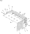
- Fig. 1 illustrates a partial perspective view showing the inside of one end part of a stacked tube body in an axis direction in an EGR cooler that is a type of an exhaust gas heat exchanger of the present invention
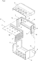
- Fig. 2 illustrates a partial perspective view of a disassembled one end part of the stacked tube body in the axis direction shown in Fig. 1
- an EGR cooler 1 includes a long and thin case 2 having an approximately square cross-section, and a long and thin stacked tube body 3 having an approximately square cross-section housed inside the case 2.
- the stacked tube body 3 is configured by stacking a plurality of flat tubes 4 in multiple tiers with spaces therebetween.
- Each of flat tubes 4 is stacked in multiple tiers with a predetermined space each other in the vertical direction in Fig. 1 , and each of upper and lower surfaces of each flat tube 4 configures a flat surface 4a.
- Exhaust gas A at a high temperature is supplied into the case 2 in the axis direction from the arrow direction and flows into the stacked tube body 3 in the axis direction. Specifically, the exhaust gas A flows in from one end part of the long and thin stacked tube body 3 in the axis direction, circulates through the inside of each flat tube 4 in the axis direction and flows out from the other end part. It is configured such that, to the case 2 at one end part of the stacked tube body 3 in the axis direction, that is, at one end part lying on a side where the exhaust gas A at high temperature flows in, cooling water B introduced from two cooling water introduction parts 5 and 6 is distributed.
- the cooling water introduction part 5 is provided for a right sidewall of the case 2 in Fig. 1
- the cooling water introduction part 6 is provided for a left sidewall of the case 2 in Fig. 1
- Introduction directions of the cooling water introduced from each of the cooling water introduction parts 5 and 6 are directions opposite to each other and, moreover, each of the introduction directions is parallel to the flat surface 4a of the flat tube 4 in the stacked tube body 3 and perpendicular in the axis direction of the flat tube 4.
- cooling water is introduced horizontally from the cooling water introduction part 5 on the right side in the left direction in Fig. 1
- cooling water is introduced horizontally from the cooling water introduction part 6 on the left side in the right direction in Fig. 1 .
- cooling water distributed to one end of the long and thin stacked tube body 3 in the axis direction circulates in the axis direction along the outer surface side of each flat tube 4 and flows out from the other end part.
- baffle plates 7 having cutout parts 8 are provided for each of the cooling water introduction parts 5 and 6 in this embodiment.
- two baffle plates 7 are formed in a plate shape and, in the inside thereof, a plurality of cutout parts 8 (detailed action thereof will be described later) are formed.
- the cooling water introduction parts 5 and 6 are linked integrally with a linking plate 9 so that the plate surfaces of the cooling water introduction parts 5 and 6 face each other, and an opening part 10 that allows the exhaust gas A to pass through is provided in the linking plate 9.
- two baffle plates 7 linked integrally with the linking plate 9 are joined integrally with the case 2 by brazing or the like.
- a receiving surface 11 that receives cooling water introduced to the cooling water introduction parts 5 and 6 and a guide surface 12 that guides the cooling water received with the receiving surface 11 to the cutout part 8 are formed.
- the receiving surface 11 is formed of a surface perpendicular in the introduction direction of cooling water
- the guide surface 12 is formed of a moderately inclined surface inclining from the receiving surface 11 in an obtuse angle direction.
- a folding erection part 13 On the end part on the side opposite to the guide surface 12 in the receiving surface 11, a folding erection part 13 whose linear long and thin tip edge is in close contact with the inner surface of the case 2 is provided, and, with the folding erection part 13, cooling water is prevented from flying in all directions from the receiving surface 11 and flowing out into the inside of the case 2.
- the folding erection part 13 is formed by folding an end part of the receiving surface 11.
- FIG. 1 and Fig. 2 one end part alone of the stacked tube body in the axis direction in an EGR cooler is shown, in Fig. 3 an appearance plan view showing the whole of the EGR cooler is shown, and in Fig. 4 an appearance side view thereof is shown. Moreover, in Fig. 5 a plan cross-sectional view showing the inside of Fig. 3 is shown.
- a supply part 15 for the exhaust gas A is provided for one end part in the axis direction of the case 2 provided in the EGR cooler 1, and a discharge part 16 for the exhaust gas A having circulated through the stacked tube body 3 is provided for the other end part.
- cooling water supply parts 5 and 6 are provided while facing each other in horizontal directions in Figs. 3 and 5 , and, near the discharge part 16 for the exhaust gas A, a discharge part 17 for a cooling water having passed along the outer periphery of the stacked tube body 3 is provided.
- Fig. 5 in order to show the inside of the case 2, the case 2 is shown with a dashed one-dotted line.
- the surface of the flat surface 4a of the flat tube 4 configuring the stacked tube body 3 is shown.
- a long and thin linear ribs 4b are formed in the vertical direction in Fig. 5 (corresponding to the horizontal direction in Fig. 1 ).
- ribs 4b have been conventionally adopted, however, in particular the rib 4b, which is formed on the surface of the flat surface 4a of one end part into which the exhaust gas A flows, distributes cooling water having been distributed to one tip part to the surface of the flat surface 4a as an arrow and enhances the flow rate in the part to thereby reduce local boiling.
- projection height of the rib 4b is set to be lower than flow path height, and a part of the cooling water flows over the rib 4b.
- a situation of distribution of the cooling water due to the rib 4b is also shown with an arrow in Fig. 1 .
- Fig. 6 illustrates a VI-VI arrow view of Fig. 5
- Fig. 7 illustrates a VII-VII arrow view of Fig. 5
- a cutout part 8 having a comb-teeth-like shape and a comparatively large opening area is formed on the upper side in Fig. 6
- a cutout part 8 having an oval shape and a small opening area is formed on the lower side.
- the cutout part 8 having a large opening area is mainly for distribution, and a greater part of cooling water passes through the cutout part 8 on the upper side having a little flow resistance and is distributed to the stacked tube body 3.
- the cutout part 8 having a small opening area is mainly for applying a brazing material to the stacked tube body 3, and has large flow resistance. Therefore, only a small amount of cooling water flows through the cutout part 8 on the lower side.
- the baffle plate 7 in Fig. 6 is set so that a greater amount of cooling water is distributed to a flat tube 4 group on the upper side than to a flat tube 4 group on the lower side in the stacked tube body 3 in Fig. 6 and, therefore, the distribution main portions thereof lie on the upper side in spaces between tube layers.
- a cutout part 8 having a comb-teeth-like shape and a comparatively large opening area is formed on the lower side in the drawing, and a cutout part 8 having an oval shape and a small opening area is formed on the upper side. That is, the baffle plate 7 in Fig. 7 is set so that a greater amount of cooling water is distributed to a flat tube 4 group on the lower side than to a flat tube 4 group on the upper side in the stacked tube body 3 in Fig. 7 and, therefore, the distribution main portions thereof lie on the lower side in spaces between tube layers.
- each cooling water that flows out from the cutout part 8 of two baffle plates 7 so as to face mutually does not interfere mutually at the center part of one end part of the stacked tube body 3 in the axis direction, and, as described above, a phenomenon of flow rate reduction of the cooling water that might occur due to the interference can be warded off to prevent local boiling of the cooling water due to flow rate reduction, as a result.
- the exhaust gas heat exchanger of the present invention is utilized as a cooler in a discharge gas recirculation system or a heat exchanger for recover heat of exhaust gas, in a diesel engine or a gasoline engine.
Landscapes
- Engineering & Computer Science (AREA)
- Physics & Mathematics (AREA)
- Mechanical Engineering (AREA)
- General Engineering & Computer Science (AREA)
- Thermal Sciences (AREA)
- Geometry (AREA)
- Chemical & Material Sciences (AREA)
- Combustion & Propulsion (AREA)
- Exhaust-Gas Circulating Devices (AREA)
- Heat-Exchange Devices With Radiators And Conduit Assemblies (AREA)
- Details Of Heat-Exchange And Heat-Transfer (AREA)
Applications Claiming Priority (2)
| Application Number | Priority Date | Filing Date | Title |
|---|---|---|---|
| JP2016003809 | 2016-01-12 | ||
| PCT/JP2017/001618 WO2017122832A1 (ja) | 2016-01-12 | 2017-01-11 | 偏平チューブ積層型の排気ガス熱交換器 |
Publications (3)
| Publication Number | Publication Date |
|---|---|
| EP3404247A1 true EP3404247A1 (de) | 2018-11-21 |
| EP3404247A4 EP3404247A4 (de) | 2019-09-04 |
| EP3404247B1 EP3404247B1 (de) | 2020-09-09 |
Family
ID=59311192
Family Applications (1)
| Application Number | Title | Priority Date | Filing Date |
|---|---|---|---|
| EP17738584.6A Active EP3404247B1 (de) | 2016-01-12 | 2017-01-11 | Abgaswärmetauscher mit gestapelten flachrohren |
Country Status (4)
| Country | Link |
|---|---|
| US (1) | US10563624B2 (de) |
| EP (1) | EP3404247B1 (de) |
| JP (1) | JP6766076B2 (de) |
| WO (1) | WO2017122832A1 (de) |
Cited By (2)
| Publication number | Priority date | Publication date | Assignee | Title |
|---|---|---|---|---|
| EP3926281A1 (de) * | 2020-06-17 | 2021-12-22 | Valeo Autosystemy SP. Z.O.O. | Wasserladeluftkühler |
| EP4015976A1 (de) * | 2020-12-15 | 2022-06-22 | Valeo Autosystemy SP. Z.O.O. | Wärmetauscher |
Families Citing this family (6)
| Publication number | Priority date | Publication date | Assignee | Title |
|---|---|---|---|---|
| EP3454001B1 (de) * | 2017-09-06 | 2020-05-06 | Borgwarner Emissions Systems Spain, S.L.U. | Kompakter wärmetauscher |
| EP3734211B1 (de) * | 2017-12-27 | 2023-08-09 | T.Rad Co., Ltd. | Sammlerplattenloser wärmetauscher |
| EP3567331B1 (de) * | 2018-05-09 | 2021-12-29 | João de Deus & Filhos, S.A. | Wärmetauscher |
| JP6496067B1 (ja) * | 2018-06-29 | 2019-04-03 | カルソニックカンセイ株式会社 | 熱交換器 |
| KR20200006779A (ko) * | 2018-07-11 | 2020-01-21 | 현대자동차주식회사 | Egr 쿨러 |
| FR3120398B1 (fr) * | 2021-03-08 | 2023-03-31 | Renault Sas | Dispositif d'échangeur à tubes de section trapézoïdale |
Family Cites Families (10)
| Publication number | Priority date | Publication date | Assignee | Title |
|---|---|---|---|---|
| JP4386215B2 (ja) | 1999-02-15 | 2009-12-16 | 臼井国際産業株式会社 | Egrガス冷却装置 |
| JP4221931B2 (ja) | 2001-07-10 | 2009-02-12 | 株式会社デンソー | 排気熱交換器 |
| US7077190B2 (en) | 2001-07-10 | 2006-07-18 | Denso Corporation | Exhaust gas heat exchanger |
| JP2005069064A (ja) | 2003-08-21 | 2005-03-17 | Hino Motors Ltd | Egrクーラ |
| JP4634291B2 (ja) | 2005-12-01 | 2011-02-16 | 株式会社ティラド | Egrクーラ |
| DE102007049184A1 (de) | 2007-10-13 | 2009-04-16 | Modine Manufacturing Co., Racine | Wärmetauscher, insbesondere Abgaswärmetauscher |
| JP2010048536A (ja) * | 2008-08-25 | 2010-03-04 | Denso Corp | 熱交換器 |
| JP2010090785A (ja) * | 2008-10-07 | 2010-04-22 | Denso Corp | 排気冷却システム |
| JP5988296B2 (ja) * | 2011-08-10 | 2016-09-07 | 臼井国際産業株式会社 | 多管式熱交換器 |
| JP6143335B2 (ja) * | 2013-03-28 | 2017-06-07 | 臼井国際産業株式会社 | 多管式熱交換器 |
-
2017
- 2017-01-11 WO PCT/JP2017/001618 patent/WO2017122832A1/ja not_active Ceased
- 2017-01-11 JP JP2017561213A patent/JP6766076B2/ja active Active
- 2017-01-11 US US16/068,716 patent/US10563624B2/en active Active
- 2017-01-11 EP EP17738584.6A patent/EP3404247B1/de active Active
Cited By (2)
| Publication number | Priority date | Publication date | Assignee | Title |
|---|---|---|---|---|
| EP3926281A1 (de) * | 2020-06-17 | 2021-12-22 | Valeo Autosystemy SP. Z.O.O. | Wasserladeluftkühler |
| EP4015976A1 (de) * | 2020-12-15 | 2022-06-22 | Valeo Autosystemy SP. Z.O.O. | Wärmetauscher |
Also Published As
| Publication number | Publication date |
|---|---|
| EP3404247B1 (de) | 2020-09-09 |
| WO2017122832A1 (ja) | 2017-07-20 |
| US10563624B2 (en) | 2020-02-18 |
| US20190017471A1 (en) | 2019-01-17 |
| JP6766076B2 (ja) | 2020-10-07 |
| EP3404247A4 (de) | 2019-09-04 |
| JPWO2017122832A1 (ja) | 2018-11-01 |
Similar Documents
| Publication | Publication Date | Title |
|---|---|---|
| EP3404247B1 (de) | Abgaswärmetauscher mit gestapelten flachrohren | |
| US9249718B2 (en) | Intercooler for vehicle | |
| KR101925201B1 (ko) | 열 교환 장치 | |
| US10202880B2 (en) | Exhaust heat exchanger | |
| US20150260466A1 (en) | Flow Deflector | |
| US20150253085A1 (en) | Heat exchange for gas, particularly the exhaust gases of an engine | |
| US20160025418A1 (en) | Heat exchanger, in particular a supercharging air cooler | |
| US10458371B2 (en) | EGR cooler | |
| KR20140111295A (ko) | 가스, 특히 엔진의 배기 가스를 위한 열교환기 | |
| EP2764231B1 (de) | Wärmetauscher für gase, insbesondere motorabgase | |
| KR102173402B1 (ko) | 차량용 egr 쿨러 | |
| US10718297B2 (en) | Exhaust gas recirculation cooler | |
| WO2020110524A1 (ja) | 熱交換器 | |
| CN110017711A (zh) | 用于热传递的设备及其制造方法 | |
| JP2017036868A (ja) | 熱交換器 | |
| US11448169B2 (en) | Vehicle exhaust gas recirculation cooler | |
| US10612496B2 (en) | Exhaust gas recirculation cooling apparatus of engine for vehicle | |
| US10851699B2 (en) | Heat exchanger for an internal combustion engine | |
| EP3594605B1 (de) | Abgasrückführungskühler | |
| KR20150001456A (ko) | 딤플이 형성된 핀 및 이를 포함하는 열교환기 | |
| EP3430340B1 (de) | Wärmetauscher für gase, insbesondere abgase von verbrennungsmotoren | |
| US20230392869A1 (en) | 221-0240 heat exchanger for a vehicle | |
| JP2016145524A (ja) | Egrクーラ | |
| JP7136757B2 (ja) | 熱交換器 | |
| KR101676271B1 (ko) | 중공 구조 하우징을 포함하는 열교환기 |
Legal Events
| Date | Code | Title | Description |
|---|---|---|---|
| STAA | Information on the status of an ep patent application or granted ep patent |
Free format text: STATUS: THE INTERNATIONAL PUBLICATION HAS BEEN MADE |
|
| PUAI | Public reference made under article 153(3) epc to a published international application that has entered the european phase |
Free format text: ORIGINAL CODE: 0009012 |
|
| STAA | Information on the status of an ep patent application or granted ep patent |
Free format text: STATUS: REQUEST FOR EXAMINATION WAS MADE |
|
| 17P | Request for examination filed |
Effective date: 20180710 |
|
| AK | Designated contracting states |
Kind code of ref document: A1 Designated state(s): AL AT BE BG CH CY CZ DE DK EE ES FI FR GB GR HR HU IE IS IT LI LT LU LV MC MK MT NL NO PL PT RO RS SE SI SK SM TR |
|
| AX | Request for extension of the european patent |
Extension state: BA ME |
|
| DAV | Request for validation of the european patent (deleted) | ||
| DAX | Request for extension of the european patent (deleted) | ||
| A4 | Supplementary search report drawn up and despatched |
Effective date: 20190807 |
|
| RIC1 | Information provided on ipc code assigned before grant |
Ipc: F28F 9/02 20060101ALI20190801BHEP Ipc: F28F 9/00 20060101ALI20190801BHEP Ipc: F02M 26/32 20160101AFI20190801BHEP Ipc: F28D 7/00 20060101ALI20190801BHEP Ipc: F28D 7/16 20060101ALI20190801BHEP Ipc: F28F 1/02 20060101ALI20190801BHEP Ipc: F28D 1/053 20060101ALI20190801BHEP Ipc: F28D 21/00 20060101ALN20190801BHEP Ipc: F28F 9/22 20060101ALI20190801BHEP |
|
| RIC1 | Information provided on ipc code assigned before grant |
Ipc: F28F 9/00 20060101ALI20200408BHEP Ipc: F28D 21/00 20060101ALN20200408BHEP Ipc: F28D 1/053 20060101ALI20200408BHEP Ipc: F28F 9/22 20060101ALI20200408BHEP Ipc: F28D 7/00 20060101ALI20200408BHEP Ipc: F28D 7/16 20060101ALI20200408BHEP Ipc: F28F 9/02 20060101ALI20200408BHEP Ipc: F28F 1/02 20060101ALI20200408BHEP Ipc: F02M 26/32 20160101AFI20200408BHEP |
|
| GRAP | Despatch of communication of intention to grant a patent |
Free format text: ORIGINAL CODE: EPIDOSNIGR1 |
|
| STAA | Information on the status of an ep patent application or granted ep patent |
Free format text: STATUS: GRANT OF PATENT IS INTENDED |
|
| RIC1 | Information provided on ipc code assigned before grant |
Ipc: F28F 9/02 20060101ALI20200504BHEP Ipc: F28D 21/00 20060101ALN20200504BHEP Ipc: F28D 1/053 20060101ALI20200504BHEP Ipc: F28F 9/00 20060101ALI20200504BHEP Ipc: F28F 9/22 20060101ALI20200504BHEP Ipc: F02M 26/32 20160101AFI20200504BHEP Ipc: F28F 1/02 20060101ALI20200504BHEP Ipc: F28D 7/16 20060101ALI20200504BHEP Ipc: F28D 7/00 20060101ALI20200504BHEP |
|
| INTG | Intention to grant announced |
Effective date: 20200525 |
|
| GRAS | Grant fee paid |
Free format text: ORIGINAL CODE: EPIDOSNIGR3 |
|
| GRAA | (expected) grant |
Free format text: ORIGINAL CODE: 0009210 |
|
| STAA | Information on the status of an ep patent application or granted ep patent |
Free format text: STATUS: THE PATENT HAS BEEN GRANTED |
|
| AK | Designated contracting states |
Kind code of ref document: B1 Designated state(s): AL AT BE BG CH CY CZ DE DK EE ES FI FR GB GR HR HU IE IS IT LI LT LU LV MC MK MT NL NO PL PT RO RS SE SI SK SM TR |
|
| REG | Reference to a national code |
Ref country code: GB Ref legal event code: FG4D |
|
| REG | Reference to a national code |
Ref country code: AT Ref legal event code: REF Ref document number: 1311876 Country of ref document: AT Kind code of ref document: T Effective date: 20200915 Ref country code: CH Ref legal event code: EP |
|
| REG | Reference to a national code |
Ref country code: IE Ref legal event code: FG4D |
|
| REG | Reference to a national code |
Ref country code: DE Ref legal event code: R096 Ref document number: 602017023335 Country of ref document: DE |
|
| REG | Reference to a national code |
Ref country code: LT Ref legal event code: MG4D |
|
| PG25 | Lapsed in a contracting state [announced via postgrant information from national office to epo] |
Ref country code: GR Free format text: LAPSE BECAUSE OF FAILURE TO SUBMIT A TRANSLATION OF THE DESCRIPTION OR TO PAY THE FEE WITHIN THE PRESCRIBED TIME-LIMIT Effective date: 20201210 Ref country code: LT Free format text: LAPSE BECAUSE OF FAILURE TO SUBMIT A TRANSLATION OF THE DESCRIPTION OR TO PAY THE FEE WITHIN THE PRESCRIBED TIME-LIMIT Effective date: 20200909 Ref country code: NO Free format text: LAPSE BECAUSE OF FAILURE TO SUBMIT A TRANSLATION OF THE DESCRIPTION OR TO PAY THE FEE WITHIN THE PRESCRIBED TIME-LIMIT Effective date: 20201209 Ref country code: FI Free format text: LAPSE BECAUSE OF FAILURE TO SUBMIT A TRANSLATION OF THE DESCRIPTION OR TO PAY THE FEE WITHIN THE PRESCRIBED TIME-LIMIT Effective date: 20200909 Ref country code: HR Free format text: LAPSE BECAUSE OF FAILURE TO SUBMIT A TRANSLATION OF THE DESCRIPTION OR TO PAY THE FEE WITHIN THE PRESCRIBED TIME-LIMIT Effective date: 20200909 Ref country code: BG Free format text: LAPSE BECAUSE OF FAILURE TO SUBMIT A TRANSLATION OF THE DESCRIPTION OR TO PAY THE FEE WITHIN THE PRESCRIBED TIME-LIMIT Effective date: 20201209 Ref country code: SE Free format text: LAPSE BECAUSE OF FAILURE TO SUBMIT A TRANSLATION OF THE DESCRIPTION OR TO PAY THE FEE WITHIN THE PRESCRIBED TIME-LIMIT Effective date: 20200909 |
|
| REG | Reference to a national code |
Ref country code: AT Ref legal event code: MK05 Ref document number: 1311876 Country of ref document: AT Kind code of ref document: T Effective date: 20200909 |
|
| REG | Reference to a national code |
Ref country code: NL Ref legal event code: MP Effective date: 20200909 |
|
| PG25 | Lapsed in a contracting state [announced via postgrant information from national office to epo] |
Ref country code: RS Free format text: LAPSE BECAUSE OF FAILURE TO SUBMIT A TRANSLATION OF THE DESCRIPTION OR TO PAY THE FEE WITHIN THE PRESCRIBED TIME-LIMIT Effective date: 20200909 Ref country code: PL Free format text: LAPSE BECAUSE OF FAILURE TO SUBMIT A TRANSLATION OF THE DESCRIPTION OR TO PAY THE FEE WITHIN THE PRESCRIBED TIME-LIMIT Effective date: 20200909 Ref country code: LV Free format text: LAPSE BECAUSE OF FAILURE TO SUBMIT A TRANSLATION OF THE DESCRIPTION OR TO PAY THE FEE WITHIN THE PRESCRIBED TIME-LIMIT Effective date: 20200909 |
|
| PG25 | Lapsed in a contracting state [announced via postgrant information from national office to epo] |
Ref country code: PT Free format text: LAPSE BECAUSE OF FAILURE TO SUBMIT A TRANSLATION OF THE DESCRIPTION OR TO PAY THE FEE WITHIN THE PRESCRIBED TIME-LIMIT Effective date: 20210111 Ref country code: RO Free format text: LAPSE BECAUSE OF FAILURE TO SUBMIT A TRANSLATION OF THE DESCRIPTION OR TO PAY THE FEE WITHIN THE PRESCRIBED TIME-LIMIT Effective date: 20200909 Ref country code: CZ Free format text: LAPSE BECAUSE OF FAILURE TO SUBMIT A TRANSLATION OF THE DESCRIPTION OR TO PAY THE FEE WITHIN THE PRESCRIBED TIME-LIMIT Effective date: 20200909 Ref country code: EE Free format text: LAPSE BECAUSE OF FAILURE TO SUBMIT A TRANSLATION OF THE DESCRIPTION OR TO PAY THE FEE WITHIN THE PRESCRIBED TIME-LIMIT Effective date: 20200909 Ref country code: SM Free format text: LAPSE BECAUSE OF FAILURE TO SUBMIT A TRANSLATION OF THE DESCRIPTION OR TO PAY THE FEE WITHIN THE PRESCRIBED TIME-LIMIT Effective date: 20200909 |
|
| PG25 | Lapsed in a contracting state [announced via postgrant information from national office to epo] |
Ref country code: IS Free format text: LAPSE BECAUSE OF FAILURE TO SUBMIT A TRANSLATION OF THE DESCRIPTION OR TO PAY THE FEE WITHIN THE PRESCRIBED TIME-LIMIT Effective date: 20210109 Ref country code: ES Free format text: LAPSE BECAUSE OF FAILURE TO SUBMIT A TRANSLATION OF THE DESCRIPTION OR TO PAY THE FEE WITHIN THE PRESCRIBED TIME-LIMIT Effective date: 20200909 Ref country code: AL Free format text: LAPSE BECAUSE OF FAILURE TO SUBMIT A TRANSLATION OF THE DESCRIPTION OR TO PAY THE FEE WITHIN THE PRESCRIBED TIME-LIMIT Effective date: 20200909 Ref country code: AT Free format text: LAPSE BECAUSE OF FAILURE TO SUBMIT A TRANSLATION OF THE DESCRIPTION OR TO PAY THE FEE WITHIN THE PRESCRIBED TIME-LIMIT Effective date: 20200909 |
|
| REG | Reference to a national code |
Ref country code: DE Ref legal event code: R097 Ref document number: 602017023335 Country of ref document: DE |
|
| PG25 | Lapsed in a contracting state [announced via postgrant information from national office to epo] |
Ref country code: SK Free format text: LAPSE BECAUSE OF FAILURE TO SUBMIT A TRANSLATION OF THE DESCRIPTION OR TO PAY THE FEE WITHIN THE PRESCRIBED TIME-LIMIT Effective date: 20200909 |
|
| PLBE | No opposition filed within time limit |
Free format text: ORIGINAL CODE: 0009261 |
|
| STAA | Information on the status of an ep patent application or granted ep patent |
Free format text: STATUS: NO OPPOSITION FILED WITHIN TIME LIMIT |
|
| 26N | No opposition filed |
Effective date: 20210610 |
|
| PG25 | Lapsed in a contracting state [announced via postgrant information from national office to epo] |
Ref country code: DK Free format text: LAPSE BECAUSE OF FAILURE TO SUBMIT A TRANSLATION OF THE DESCRIPTION OR TO PAY THE FEE WITHIN THE PRESCRIBED TIME-LIMIT Effective date: 20200909 Ref country code: SI Free format text: LAPSE BECAUSE OF FAILURE TO SUBMIT A TRANSLATION OF THE DESCRIPTION OR TO PAY THE FEE WITHIN THE PRESCRIBED TIME-LIMIT Effective date: 20200909 Ref country code: MC Free format text: LAPSE BECAUSE OF FAILURE TO SUBMIT A TRANSLATION OF THE DESCRIPTION OR TO PAY THE FEE WITHIN THE PRESCRIBED TIME-LIMIT Effective date: 20200909 |
|
| REG | Reference to a national code |
Ref country code: CH Ref legal event code: PL |
|
| GBPC | Gb: european patent ceased through non-payment of renewal fee |
Effective date: 20210111 |
|
| PG25 | Lapsed in a contracting state [announced via postgrant information from national office to epo] |
Ref country code: LU Free format text: LAPSE BECAUSE OF NON-PAYMENT OF DUE FEES Effective date: 20210111 |
|
| REG | Reference to a national code |
Ref country code: BE Ref legal event code: MM Effective date: 20210131 |
|
| PG25 | Lapsed in a contracting state [announced via postgrant information from national office to epo] |
Ref country code: IT Free format text: LAPSE BECAUSE OF FAILURE TO SUBMIT A TRANSLATION OF THE DESCRIPTION OR TO PAY THE FEE WITHIN THE PRESCRIBED TIME-LIMIT Effective date: 20200909 Ref country code: FR Free format text: LAPSE BECAUSE OF NON-PAYMENT OF DUE FEES Effective date: 20210131 |
|
| PG25 | Lapsed in a contracting state [announced via postgrant information from national office to epo] |
Ref country code: CH Free format text: LAPSE BECAUSE OF NON-PAYMENT OF DUE FEES Effective date: 20210131 Ref country code: GB Free format text: LAPSE BECAUSE OF NON-PAYMENT OF DUE FEES Effective date: 20210111 Ref country code: LI Free format text: LAPSE BECAUSE OF NON-PAYMENT OF DUE FEES Effective date: 20210131 |
|
| PG25 | Lapsed in a contracting state [announced via postgrant information from national office to epo] |
Ref country code: IE Free format text: LAPSE BECAUSE OF NON-PAYMENT OF DUE FEES Effective date: 20210111 |
|
| PG25 | Lapsed in a contracting state [announced via postgrant information from national office to epo] |
Ref country code: IS Free format text: LAPSE BECAUSE OF FAILURE TO SUBMIT A TRANSLATION OF THE DESCRIPTION OR TO PAY THE FEE WITHIN THE PRESCRIBED TIME-LIMIT Effective date: 20210109 |
|
| PG25 | Lapsed in a contracting state [announced via postgrant information from national office to epo] |
Ref country code: BE Free format text: LAPSE BECAUSE OF NON-PAYMENT OF DUE FEES Effective date: 20210131 |
|
| PG25 | Lapsed in a contracting state [announced via postgrant information from national office to epo] |
Ref country code: NL Free format text: LAPSE BECAUSE OF NON-PAYMENT OF DUE FEES Effective date: 20200923 Ref country code: CY Free format text: LAPSE BECAUSE OF FAILURE TO SUBMIT A TRANSLATION OF THE DESCRIPTION OR TO PAY THE FEE WITHIN THE PRESCRIBED TIME-LIMIT Effective date: 20200909 |
|
| PG25 | Lapsed in a contracting state [announced via postgrant information from national office to epo] |
Ref country code: HU Free format text: LAPSE BECAUSE OF FAILURE TO SUBMIT A TRANSLATION OF THE DESCRIPTION OR TO PAY THE FEE WITHIN THE PRESCRIBED TIME-LIMIT; INVALID AB INITIO Effective date: 20170111 |
|
| PG25 | Lapsed in a contracting state [announced via postgrant information from national office to epo] |
Ref country code: MK Free format text: LAPSE BECAUSE OF FAILURE TO SUBMIT A TRANSLATION OF THE DESCRIPTION OR TO PAY THE FEE WITHIN THE PRESCRIBED TIME-LIMIT Effective date: 20200909 |
|
| PG25 | Lapsed in a contracting state [announced via postgrant information from national office to epo] |
Ref country code: TR Free format text: LAPSE BECAUSE OF FAILURE TO SUBMIT A TRANSLATION OF THE DESCRIPTION OR TO PAY THE FEE WITHIN THE PRESCRIBED TIME-LIMIT Effective date: 20200909 |
|
| PG25 | Lapsed in a contracting state [announced via postgrant information from national office to epo] |
Ref country code: MT Free format text: LAPSE BECAUSE OF FAILURE TO SUBMIT A TRANSLATION OF THE DESCRIPTION OR TO PAY THE FEE WITHIN THE PRESCRIBED TIME-LIMIT Effective date: 20200909 |
|
| PGFP | Annual fee paid to national office [announced via postgrant information from national office to epo] |
Ref country code: DE Payment date: 20251203 Year of fee payment: 10 |