EP3404979B1 - Verfahren und vorrichtung zur übertragung von downlink-steuerinformationen - Google Patents
Verfahren und vorrichtung zur übertragung von downlink-steuerinformationen Download PDFInfo
- Publication number
- EP3404979B1 EP3404979B1 EP17746799.0A EP17746799A EP3404979B1 EP 3404979 B1 EP3404979 B1 EP 3404979B1 EP 17746799 A EP17746799 A EP 17746799A EP 3404979 B1 EP3404979 B1 EP 3404979B1
- Authority
- EP
- European Patent Office
- Prior art keywords
- dci
- scheduled
- information field
- resource
- occupied
- Prior art date
- Legal status (The legal status is an assumption and is not a legal conclusion. Google has not performed a legal analysis and makes no representation as to the accuracy of the status listed.)
- Active
Links
Images


Classifications
-
- H—ELECTRICITY
- H04—ELECTRIC COMMUNICATION TECHNIQUE
- H04W—WIRELESS COMMUNICATION NETWORKS
- H04W72/00—Local resource management
- H04W72/20—Control channels or signalling for resource management
- H04W72/23—Control channels or signalling for resource management in the downlink direction of a wireless link, i.e. towards a terminal
- H04W72/232—Control channels or signalling for resource management in the downlink direction of a wireless link, i.e. towards a terminal the control data signalling from the physical layer, e.g. DCI signalling
-
- H—ELECTRICITY
- H04—ELECTRIC COMMUNICATION TECHNIQUE
- H04W—WIRELESS COMMUNICATION NETWORKS
- H04W72/00—Local resource management
- H04W72/20—Control channels or signalling for resource management
- H04W72/23—Control channels or signalling for resource management in the downlink direction of a wireless link, i.e. towards a terminal
-
- H—ELECTRICITY
- H04—ELECTRIC COMMUNICATION TECHNIQUE
- H04L—TRANSMISSION OF DIGITAL INFORMATION, e.g. TELEGRAPHIC COMMUNICATION
- H04L5/00—Arrangements affording multiple use of the transmission path
- H04L5/003—Arrangements for allocating sub-channels of the transmission path
- H04L5/0037—Inter-user or inter-terminal allocation
-
- H—ELECTRICITY
- H04—ELECTRIC COMMUNICATION TECHNIQUE
- H04B—TRANSMISSION
- H04B7/00—Radio transmission systems, i.e. using radiation field
- H04B7/02—Diversity systems; Multi-antenna system, i.e. transmission or reception using multiple antennas
- H04B7/04—Diversity systems; Multi-antenna system, i.e. transmission or reception using multiple antennas using two or more spaced independent antennas
- H04B7/0413—MIMO systems
-
- H—ELECTRICITY
- H04—ELECTRIC COMMUNICATION TECHNIQUE
- H04L—TRANSMISSION OF DIGITAL INFORMATION, e.g. TELEGRAPHIC COMMUNICATION
- H04L1/00—Arrangements for detecting or preventing errors in the information received
- H04L1/0001—Systems modifying transmission characteristics according to link quality, e.g. power backoff
- H04L1/0002—Systems modifying transmission characteristics according to link quality, e.g. power backoff by adapting the transmission rate
- H04L1/0003—Systems modifying transmission characteristics according to link quality, e.g. power backoff by adapting the transmission rate by switching between different modulation schemes
-
- H—ELECTRICITY
- H04—ELECTRIC COMMUNICATION TECHNIQUE
- H04L—TRANSMISSION OF DIGITAL INFORMATION, e.g. TELEGRAPHIC COMMUNICATION
- H04L1/00—Arrangements for detecting or preventing errors in the information received
- H04L1/12—Arrangements for detecting or preventing errors in the information received by using return channel
- H04L1/16—Arrangements for detecting or preventing errors in the information received by using return channel in which the return channel carries supervisory signals, e.g. repetition request signals
- H04L1/18—Automatic repetition systems, e.g. Van Duuren systems
- H04L1/1812—Hybrid protocols; Hybrid automatic repeat request [HARQ]
-
- H—ELECTRICITY
- H04—ELECTRIC COMMUNICATION TECHNIQUE
- H04L—TRANSMISSION OF DIGITAL INFORMATION, e.g. TELEGRAPHIC COMMUNICATION
- H04L1/00—Arrangements for detecting or preventing errors in the information received
- H04L1/12—Arrangements for detecting or preventing errors in the information received by using return channel
- H04L1/16—Arrangements for detecting or preventing errors in the information received by using return channel in which the return channel carries supervisory signals, e.g. repetition request signals
- H04L1/18—Automatic repetition systems, e.g. Van Duuren systems
- H04L1/1822—Automatic repetition systems, e.g. Van Duuren systems involving configuration of automatic repeat request [ARQ] with parallel processes
-
- H—ELECTRICITY
- H04—ELECTRIC COMMUNICATION TECHNIQUE
- H04L—TRANSMISSION OF DIGITAL INFORMATION, e.g. TELEGRAPHIC COMMUNICATION
- H04L1/00—Arrangements for detecting or preventing errors in the information received
- H04L1/12—Arrangements for detecting or preventing errors in the information received by using return channel
- H04L1/16—Arrangements for detecting or preventing errors in the information received by using return channel in which the return channel carries supervisory signals, e.g. repetition request signals
- H04L1/18—Automatic repetition systems, e.g. Van Duuren systems
- H04L1/1867—Arrangements specially adapted for the transmitter end
- H04L1/1896—ARQ related signaling
-
- H—ELECTRICITY
- H04—ELECTRIC COMMUNICATION TECHNIQUE
- H04L—TRANSMISSION OF DIGITAL INFORMATION, e.g. TELEGRAPHIC COMMUNICATION
- H04L5/00—Arrangements affording multiple use of the transmission path
- H04L5/003—Arrangements for allocating sub-channels of the transmission path
- H04L5/0044—Allocation of payload; Allocation of data channels, e.g. PDSCH or PUSCH
-
- H—ELECTRICITY
- H04—ELECTRIC COMMUNICATION TECHNIQUE
- H04L—TRANSMISSION OF DIGITAL INFORMATION, e.g. TELEGRAPHIC COMMUNICATION
- H04L5/00—Arrangements affording multiple use of the transmission path
- H04L5/003—Arrangements for allocating sub-channels of the transmission path
- H04L5/0053—Allocation of signalling, i.e. of overhead other than pilot signals
-
- H—ELECTRICITY
- H04—ELECTRIC COMMUNICATION TECHNIQUE
- H04L—TRANSMISSION OF DIGITAL INFORMATION, e.g. TELEGRAPHIC COMMUNICATION
- H04L5/00—Arrangements affording multiple use of the transmission path
- H04L5/0091—Signalling for the administration of the divided path, e.g. signalling of configuration information
-
- H—ELECTRICITY
- H04—ELECTRIC COMMUNICATION TECHNIQUE
- H04L—TRANSMISSION OF DIGITAL INFORMATION, e.g. TELEGRAPHIC COMMUNICATION
- H04L5/00—Arrangements affording multiple use of the transmission path
- H04L5/003—Arrangements for allocating sub-channels of the transmission path
- H04L5/0053—Allocation of signalling, i.e. of overhead other than pilot signals
- H04L5/0055—Physical resource allocation for ACK/NACK
-
- H—ELECTRICITY
- H04—ELECTRIC COMMUNICATION TECHNIQUE
- H04W—WIRELESS COMMUNICATION NETWORKS
- H04W72/00—Local resource management
- H04W72/04—Wireless resource allocation
- H04W72/044—Wireless resource allocation based on the type of the allocated resource
- H04W72/0446—Resources in time domain, e.g. slots or frames
-
- H—ELECTRICITY
- H04—ELECTRIC COMMUNICATION TECHNIQUE
- H04W—WIRELESS COMMUNICATION NETWORKS
- H04W72/00—Local resource management
- H04W72/04—Wireless resource allocation
- H04W72/044—Wireless resource allocation based on the type of the allocated resource
- H04W72/0453—Resources in frequency domain, e.g. a carrier in FDMA
Definitions
- the present invention relates to the field of communications, and particularly to a method and apparatus for transmitting downlink control information.
- the next generation of mobile communication technologies the mobile internet is providing its users with augmented reality, virtual reality, ultra high-definition (3D) videos, a mobile cloud, and other more abundant service experiences.
- the Internet of Things extends a service scope of mobile communication from human to human communication to intelligent human to thing, and thing to thing intercommunication, so that the mobile communication technologies are pervaded into more industries and fields.
- Future system resources can be divided into different sub-bands for different services, and the sub-bands can be allocated with Transmission Time Intervals (TTIs) with different lengths to thereby satisfy various service demands.
- TTIs Transmission Time Intervals
- Fig. 1 illustrates a frame structure (Frame Structure Type 1 or FS1) in an existing LTE Frequency Division Duplex (FDD) system.
- FDD Frequency Division Duplex
- a radio frame with a length of 10ms includes ten 1ms sub-frames, and each sub-frame is subdivided into two timeslots with a length of 0.5ms.
- a length of time for a TTI in which uplink and downlink data are transmitted is 1ms.
- FIG. 2 illustrates a frame structure (Frame Structure Type 2 or FS2) in an existing LTE TDD system.
- FS2 Frame Structure Type 2
- Each 10ms radio frame in the FS2 includes two 5ms half-frames, and each half-frame includes five 1ms sub-frames.
- the sub-frames in the FS2 are categorized into three categories: downlink sub-frames, uplink sub-frames, and special sub-frames, where each special sub-frame includes three components of a Downlink Pilot Time Slot (DwPTS), a Guard Period (GP), and an Uplink Pilot Time Slot (UpPTS).
- DwPTS Downlink Pilot Time Slot
- GP Guard Period
- UpPTS Uplink Pilot Time Slot
- Each half-frame includes at least one downlink sub-frame and at least one uplink sub-frame, and at most one special sub-frame.
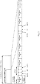
- Table 1 depicts seven uplink-downlink sub-frame configuration patterns supported in the FS2.
- Uplink-downlink configurations Uplink-down link configuration Downlink-to-Uplink Switch-point periodicity Sub-frame number 0 1 2 3 4 5 6 7 8 9 0 5 ms D S U U U D S U U U 1 5 ms D S U U D D S U U D 2 5 ms D S U D D D S U D D 3 10 ms D S U U U D D D D D D 4 10 ms D S U U D D D D D D D 5 10 ms D S U D D D D D D D D D 6 5 ms D S U U U U D S U U D (3) Downlink resource granularities in the existing LTE system: in the existing LTE system, the smallest resource granularity in the time domain is an Orthogonal Frequency Division Multiplexing (OFDM) symbol, and the smallest resource granularity in the frequency domain is a sub-carrier.
- OFDM Orthogonal Frequency Division Multiplexing
- a PRB is a resource element in a larger dimension, and includes N symb DL ⁇ N sc RB REs.
- a sub-frame includes a PRB pair, and the PRB pair is an elementary unit at which a data resource is allocated.
- DCI formats in the existing LTE system Downlink Control Information (DCI) is carried in a Physical Downlink Control Channel (DCI) to transmit uplink/downlink scheduling information and related common control information.
- DCI formats 0 and 4 are used to schedule uplink data
- DCI formats 1, 1A, 1B, 1C, 1D, 2, 2A, 2B, and 2C are used to schedule downlink data; and there are different numbers of information bits, and different meanings of information fields, in respective formats of the DCI for different transmission modes or uses thereof.
- the DCI includes the majority of information required for scheduling a User Equipment (UE), e.g., resource allocation information, a Modulation and Coding Scheme (MCS), a Hybrid Automatic Repeated Request (HARQ) ID, a New Data Indicator (NDI), etc.
- UE User Equipment
- MCS Modulation and Coding Scheme
- HARQ Hybrid Automatic Repeated Request
- NDI New Data Indicator
- the length of a TTI is fixed at 1ms, and the smallest granularity at which a resource is allocated is a PRB.
- the existing DCI can only be used to schedule a resource with the length of 1ms in a TTI, a resource is scheduled at the smallest granularity of a PRB, and a UE is allocated with consecutive or inconsecutive resources at the smallest granularity of a PRB or a Resource Block Group (RGB) in a TTI.
- RGB Resource Block Group
- DCIs are periodically transmitted on a PDSCH channel and contain scheduling information.
- DCIs provide uplink and downlink allocations, acknowledge uplink messages and configure the random access resources.
- An allocation is a physical resource on the PBSCH or PUSCH channels.
- a downlink or uplink allocation description in a DCI defines the start time, length and which physical channel the resource is on.
- the UEs receive DCIs in a chain when they are not otherwise transmitting or receiving.
- the DCI burst packet format consists of a length, followed by a payload and CRC.
- the DCI Packet Payload is variable length and contains retransmission scheme processing information, downlink allocations, uplink allocations and RACH allocations.
- US20150016361 patent application discloses a method for receiving information for interference cancellation of a mobile terminal, the method comprising: receiving, from a base station, multi-user downlink control information (MU DCI) including CRC scrambled with an identifier (ID) of a user group, the MU DCI including control information for a plurality of mobile terminals belonging to the user group, information indicating the number of mobile terminals simultaneously scheduled by the MU DCI in a subframe, and an index allocated to each mobile terminal being added to the end of the control information for each mobile terminal; and receiving downlink data for other mobile terminals in the user group using the control information for the other mobile terminals if the control information for the mobile terminal is included in the MU DCI.
- MU DCI multi-user downlink control information
- ID identifier
- US20130195041 patent application discloses that: methods and apparatus are described for a User Equipment (UE) with reduced processing capabilities (e.g., Machine Type Communication (MTC) UE) to transmit and receive signaling are provided.
- the Downlink Control Information (DCI) formats scheduling a transmission of a Physical Uplink Shared Channel (PUSCH) or a reception of a Physical Downlink Shared Channel (PDSCH) are designed and have a smaller size than respective DCI formats for conventional UEs.
- DCI formats scheduling PUSCHs to or PDSCHs for a group of MTC UEs are also designed and can have a same size as DCI formats scheduling PUSCH or PDSCH for an individual MTC UE.
- Embodiments of the invention provide a method and apparatus for transmitting downlink control information so as to enable downlink control information to be transmitted in a scenario where a resource is allocated flexibly in a variable transmission time interval.
- An embodiment of the invention provides a method for transmitting Downlink Control Information (DCI), the method including: transmitting the DCI, wherein the DCI includes: a first information field indicating a frequency resource occupied by a data resource scheduled by the DCI, and a second information field indicating a time resource occupied by the data resource scheduled by the DCI; wherein the time resource occupied by the data resource scheduled by the DCI includes: the quantity of symbols occupied by the data resource scheduled by the DCI; or the quantity of symbols occupied by the data resource scheduled by the DCI, and a start symbol index of the symbols; or a length of a Transmission Time Interval (TTI) for data transmission scheduled by the DCI; or a length of a Transmission Time Interval (TTI) for data transmission scheduled by the DCI, and a time domain start position of the data transmission.
- DCI Downlink Control Information
- the frequency resource occupied by the data resource scheduled by the DCI includes: the quantity of resource blocks occupied by the data resource scheduled by the DCI; or the quantity of resource blocks occupied by the data resource scheduled by the DCI, and a resource start position of the resource blocks; or the quantity of resource elements occupied by the data resource scheduled by the DCI; or the quantity of resource elements occupied by the data resource scheduled by the DCI, and a start index of the resource elements; or the quantity of sub-carriers occupied by the data resource scheduled by the DCI; or the quantity of sub-carriers occupied by the data resource scheduled by the DCI, and a start index of the sub-carriers.
- the DCI further includes a third information field indicating N scheduled users, wherein N is an integer greater than or equal to 1; wherein before the DCI is transmitted, the method further includes: allocating, by a base station, transmission resources for the N scheduled users; and/or, after the DCI is transmitted, the method further includes: transmitting, by a base station, data with the N scheduled users over allocated transmission resources.
- the DCI further includes one or any combination of following information fields: a fourth information field indicating a Modulation and Coding Scheme (MCS), or a group of MCSs; a fifth information field indicating a piece of or a group of pieces of multi-input multi-output channel information; a sixth information field indicating a Hybrid Automatic Repeated Request (HARQ) process identifier or a group of HARQ process identifiers; a seventh information field indicating a piece of or a group of pieces of Acknowledgement/Non-acknowledgement (ACK/NACK) information of an uplink Hybrid Automatic Repeated Request (HARQ); an eighth information field indicating a type of transmission and/or a type of service; or, a ninth information field, wherein the ninth information field indicates whether a group of scheduled users are equally allocated with a time-frequency resource region indicated by the first information field and the second information field in the DCI, wherein equal allocation refers to equal allocation in a time domain or in a frequency
- Another embodiment of the invention provides a method for transmitting Downlink Control Information (DCI), the method including: receiving the DCI, wherein the DCI includes: a first information field indicating a frequency resource occupied by a data resource scheduled by the DCI, and a second information field indicating a time resource occupied by the data resource scheduled by the DCI; wherein the time resource occupied by the data resource scheduled by the DCI includes: the quantity of symbols occupied by the data resource scheduled by the DCI; or the quantity of symbols occupied by the data resource scheduled by the DCI, and a start symbol index of the symbols; or a length of a Transmission Time Interval (TTI) for data transmission scheduled by the DCI; or a length of a Transmission Time Interval (TTI) for data transmission scheduled by the DCI, and a time domain start position of the data transmission.
- DCI Downlink Control Information
- the frequency resource occupied by the data resource scheduled by the DCI includes: the quantity of resource blocks occupied by the data resource scheduled by the DCI; or the quantity of resource blocks occupied by the data resource scheduled by the DCI, and a resource start position of the resource blocks; or the quantity of resource elements occupied by the data resource scheduled by the DCI; or the quantity of resource elements occupied by the data resource scheduled by the DCI, and a start index of the resource elements; or the quantity of sub-carriers occupied by the data resource scheduled by the DCI; or the quantity of sub-carriers occupied by the data resource scheduled by the DCI, and a start index of the sub-carriers.
- the DCI further includes a third information field indicating N scheduled users, wherein N is an integer greater than or equal to 1; wherein after the DCI is received, the method further includes: receiving or transmitting data over a transmission resource allocated by a base station.
- the DCI further includes one or any combination of following information fields: a fourth information field indicating a Modulation and Coding Scheme (MCS), or a group of MCSs; a fifth information field indicating a piece of or a group of pieces of multi-input multi-output channel information; a sixth information field indicating a Hybrid Automatic Repeated Request (HARQ) process identifier or a group of HARQ process identifiers; a seventh information field indicating a piece of or a group of pieces of Acknowledgement/Non-acknowledgement (ACK/NACK) information of an uplink Hybrid Automatic Repeated Request (HARQ); an eighth information field indicating a type of transmission and/or a type of service; or, a ninth information field, wherein the ninth information field indicates whether a group of scheduled users are equally allocated with a time-frequency resource region indicated by the first information field and the second information field in the DCI, wherein equal allocation refers to equal allocation in a time domain or in a frequency
- An embodiment of the invention provides a base station including: a sending module configured to transmit Downlink Control Information (DCI), wherein the DCI includes: a first information field indicating a frequency resource occupied by a data resource scheduled by the DCI, and a second information field indicating a time resource occupied by the data resource scheduled by the DCI; wherein the time resource occupied by the data resource scheduled by the DCI includes: the quantity of symbols occupied by the data resource scheduled by the DCI; or the quantity of symbols occupied by the data resource scheduled by the DCI, and a start symbol index of the symbols; or a length of a Transmission Time Interval (TTI) for data transmission scheduled by the DCI; or a length of a Transmission Time Interval (TTI) for data transmission scheduled by the DCI, and a time domain start position of the data transmission.
- DCI Downlink Control Information
- the frequency resource occupied by the data resource scheduled by the DCI includes: the quantity of resource blocks occupied by the data resource scheduled by the DCI; or the quantity of resource blocks occupied by the data resource scheduled by the DCI, and a resource start position of the resource blocks; or the quantity of resource elements occupied by the data resource scheduled by the DCI; or the quantity of resource elements occupied by the data resource scheduled by the DCI, and a start index of the resource elements; or the quantity of sub-carriers occupied by the data resource scheduled by the DCI; or the quantity of sub-carriers occupied by the data resource scheduled by the DCI, and a start index of the sub-carriers.
- the DCI further includes a third information field indicating N scheduled users, wherein N is an integer greater than or equal to 1; wherein the base station further includes: an allocating module configured to allocate transmission resources for the N scheduled users before the DCI is transmitted; and/or, a transmitting module configured to transmit data with the N scheduled users over allocated transmission resources after the DCI is transmitted.
- the DCI further includes one or any combination of following information fields: a fourth information field indicating a Modulation and Coding Scheme (MCS), or a group of MCSs; a fifth information field indicating a piece of or a group of pieces of multi-input multi-output channel information; a sixth information field indicating a Hybrid Automatic Repeated Request (HARQ) process identifier or a group of HARQ process identifiers; a seventh information field indicating a piece of or a group of pieces of Acknowledgement/Non-acknowledgement (ACK/NACK) information of an uplink Hybrid Automatic Repeated Request (HARQ); an eighth information field indicating a type of transmission and/or a type of service; or, a ninth information field, wherein the ninth information field indicates whether a group of scheduled users are equally allocated with a time-frequency resource region indicated by the first information field and the second information field in the DCI, wherein equal allocation refers to equal allocation in a time domain or in a frequency
- An embodiment of the invention provides a User Equipment (UE) including: a receiving module configured to receive Downlink Control Information (DCI), wherein the DCI includes at least one or more of following information fields: a first information field indicating a frequency resource occupied by a data resource scheduled by the DCI, a second information field indicating a time resource occupied by the data resource scheduled by the DCI, and a third information field indicating N scheduled users, wherein N is an integer greater than or equal to 1.
- DCI Downlink Control Information
- the frequency resource occupied by the data resource scheduled by the DCI includes: the quantity of resource blocks occupied by the data resource scheduled by the DCI; or the quantity of resource blocks occupied by the data resource scheduled by the DCI, and a resource start position of the resource blocks; or the quantity of resource elements occupied by the data resource scheduled by the DCI; or the quantity of resource elements occupied by the data resource scheduled by the DCI, and a start index of the resource elements; or the quantity of sub-carriers occupied by the data resource scheduled by the DCI; or the quantity of sub-carriers occupied by the data resource scheduled by the DCI, and a start index of the sub-carriers.
- the time resource occupied by the data resource scheduled by the DCI includes: the quantity of symbols occupied by the data resource scheduled by the DCI; or the quantity of symbols occupied by the data resource scheduled by the DCI, and a start symbol index of the symbols; or a length of a Transmission Time Interval (TTI) for data transmission scheduled by the DCI; or a length of a Transmission Time Interval (TTI) for data transmission scheduled by the DCI, and a time domain start position of the data transmission.
- TTI Transmission Time Interval
- TTI Transmission Time Interval
- the third information field indicates user identifiers of the N scheduled users.
- the DCI further includes one or any combination of following information fields: a fourth information field indicating a Modulation and Coding Scheme (MCS), or a group of MCSs; a fifth information field indicating a piece of or a group of pieces of multi-input multi-output channel information; a sixth information field indicating a Hybrid Automatic Repeated Request (HARQ) process identifier or a group of HARQ process identifiers; a seventh information field indicating a piece of or a group of pieces of Acknowledgement/Non-acknowledgement (ACK/NACK) information of an uplink Hybrid Automatic Repeated Request (HARQ); or an eighth information field indicating a type of transmission and/or a type of service.
- MCS Modulation and Coding Scheme
- HARQ Hybrid Automatic Repeated Request
- ACK/NACK Acknowledgement/Non-acknowledgement
- the seventh information field exists in DCI for scheduling uplink transmission.
- the DCI further includes a ninth information field, wherein the ninth information field indicates whether a group of scheduled UEs are equally allocated with a time-frequency resource region indicated by the first information field and the second information field in the DCI, wherein equal allocation refers to equal allocation in a time domain or in a frequency domain.
- the UE further includes: a transmitting module configured to receive or transmit data over a transmission resource allocated by a base station after the DCI is received.
- a base station including: a processor, a memory, a transceiver, and a bus interface, wherein: the processor is configured to read and execute programs in the memory to: transmit Downlink Control Information (DCI), wherein the DCI includes at least one or more of following information fields: a first information field indicating a frequency resource occupied by a data resource scheduled by the DCI, a second information field indicating a time resource occupied by the data resource scheduled by the DCI, and a third information field indicating N scheduled users, where N is an integer greater than or equal to 1.
- DCI Downlink Control Information
- a User Equipment including: a processor, a memory, a transceiver, and a bus interface, wherein: the processor is configured to read and execute programs in the memory to: receive Downlink Control Information (DCI), wherein the DCI includes at least one or more of following information fields: a first information field indicating a frequency resource occupied by a data resource scheduled by the DCI, a second information field indicating a time resource occupied by the data resource scheduled by the DCI, and a third information field indicating N scheduled users, where N is an integer greater than or equal to 1.
- DCI Downlink Control Information
- transmitted downlink control information includes at least one or more of the following information fields: a first information field indicating a frequency resource occupied by a data resource scheduled by the DCI, a second information field indicating a time resource occupied by the data resource scheduled by the DCI, and a third information field indicating N scheduled users. Since the downlink control information can indicate one or more of the following information: the frequency resource occupied by the data resource scheduled by the DCI, e.g., resource elements or sub-carriers, and the time resource occupied by the data resource scheduled by the DCI, e.g., symbols occupied in the time domain, the downlink control information can be transmitted in a scenario where a resource is allocated flexibly in a variable transmission time interval.
- a future mobile communication system needs to provide a shorter network delay, and to support more abundant types of services, so dynamic configuration of the length of a TTI and resources occupied in the TTI (e.g., several RUs or even several REs, where the RU stands for a Resource Unit, which can include one or more sub-carriers in the frequency domain, and one or more symbols in the time domain) according to a service demand becomes a trend of technology development.
- the embodiments of the invention propose a solution to transmitting DCI over a flexibly configured resource in a variable TTI in this scenario where a resource is allocated flexibly.
- the base station can be an Evolutional Node B (eNB or e-NodeB, for short), a macro eNB, a micro eNB (referred to a small eNB), a pico eNB, an Access Point (AP), or a Transmission Point (TP), in an LTE system, a base station in a next generation of wireless communication system, etc., or the base station can be conceptualized as including cells or sectors, although the embodiments of the invention will not be limited thereto.
- eNB Evolutional Node B
- e-NodeB for short
- a macro eNB a micro eNB
- AP Access Point
- TP Transmission Point
- the UE can be a handheld device, an on-vehicle device, a wearable device, a computing device, or another processing device connected with a wireless modem, and various forms of UEs, Mobile Stations (MSs), terminals, terminal equipment, etc., with a wireless communication function although the embodiments of the invention will not be limited thereto.
- MSs Mobile Stations
- terminals terminal equipment, etc.
- the LTE system can be regarded as corresponding to the 3 rd Generation Partnership Project (3GPP) Release 8 (Rel-8 or R8), Release 9 (Rel-9 or R9), Release 10 (Rel-10 or R10), and Releases subsequent thereto
- the LTE network can be structured as a macro cellular, a micro cellular, a pico cellular, a femto network, a network including repeaters and forwarding nodes, or various hybrid network structures (including one or more of the macro cellular, the micro cellular, the pico cellular, the femto network, and the repeaters and forwarding nodes), etc., although the embodiments of the invention will not be limited thereto.
- Fig. 4 is a schematic flow chart of transmitting DCI at a network side according to an embodiment of the invention, the flow can be performed by a base station.
- the flow can include the following operations.
- the operation 402 is to transmit the DCI, where the DCI includes at least one or more of following information fields: a first information field indicating a frequency resource occupied by a data resource scheduled by the DCI, a second information field indicating a time resource occupied by the data resource scheduled by the DCI, and a third information field indicating N scheduled users (e.g., UEs, where the same will apply hereinafter), where N is an integer greater than or equal to 1.
- the DCI can include the first information field indicating a size of the frequency resource occupied by the data resource scheduled by the DCI, and for example, the information field can indicate a size of an occupied resource, or a position and a size of an occupied resource, etc.; and the second information field indicating a size of the time resource occupied by the data resource scheduled by the DCI.
- the first information field can indicate the quantity of RBs occupied by the data resource scheduled by the DCI, or the quantity of resource elements occupied by the data resource scheduled by the DCI, or the quantity of sub-carriers occupied by the data resource scheduled by the DCI.
- the resource element can be an RU which is a resource region occupying X1 sub-carriers in a frequency domain, and X2 symbols in a time domain, where both X1 and X2 are integers greater than or equal to 1, and their values can be agreed on in advance, or can be configured at a higher layer.
- the resource element can alternatively be an RE which is a resource region occupying one sub-carrier in the frequency domain, and one symbol in the time domain.
- the symbol can be an OFDM symbol.
- the second information field can indicate the quantity of symbols occupied by the data resource scheduled by the DCI, or a length of a TTI occupied by the data resource scheduled by the DCI.
- the third information field can indicate an ID of a scheduled UE or IDs of a group of scheduled UEs, where when the UE or UEs are scheduled to transmit in the uplink, the UE or UEs corresponding to the ID or the IDs is or are a UE or UEs to transmit data; and when the UE or UEs are scheduled to transmit in the downlink, the UE or UEs corresponding to the ID or the IDs is or are a UE or UEs to receive data.
- DCI can further include one or any combination of the following fourth information field to eighth information field.
- the DCI above can further include a ninth information field, where the ninth information field indicates whether a group of scheduled UEs are equally allocated with a time-frequency resource region indicated by the first information field and the second information field in the DCI, where equal allocation refers to equal allocation in the time domain or in the frequency domain.
- the DCI may alternatively not include the ninth information field above, but it can be determined as agreed on in advance whether to equally allocate for a group of scheduled UEs a time-frequency resource region indicated by the first information field and the second information field in the DCI, or a time-frequency resource region indicated by the first information field and the second information field in the DCI can be allocated for a group of scheduled UEs under a rule agreed on in advance.
- a time-frequency resource region indicated by the first information field and the second information field in the DCI may be equally allocated for the group of UE according to an equal allocation flag carried in the ninth information field in the DCI, and an MCS level, and other common information, indicated in the DCI may be shared to thereby lower an overhead.
- the respective information fields will be shared (e.g., information fields indicating an MCS level, MIMO channel information, etc.), and allocated time-frequency resources may also be different. In this case, the ninth information field may not necessarily exist.
- the DCI above can include one or more of the first information field to the third information field, and furthermore can further include one or more of the fourth information field to the ninth information field.
- the respective information fields in the DCI above can be arranged in the DCI in an order agreed on in advance, although the embodiments of the invention will not be limited to any particular order in which the respective information fields are arranged.
- the base station can transmit the DCI in a PDCCH.
- the method can further include the following operation before the operation 402.
- the base station allocates transmission resources for the N scheduled users.
- the base station can configure a length of a TTI, and time-frequency resources for transmitting data in the TTI, dynamically according to a service demand, where the time-frequency resources can include several RUs or several REs.
- the method can further include the following operation after the operation 402.
- the base station transmits data with the N scheduled users over the allocated transmission resources.
- the base station receives data transmitted by the UE or the UEs corresponding to the UE ID or the group of UE IDs; and when the UE or UEs is or are scheduled to transmit in the downlink, the base station transmits data to the UE or the UEs corresponding to the UE ID or the group of UE IDs.
- transmitted DCI includes at least one or more of the following information fields: a first information field indicating a frequency resource occupied by a data resource scheduled by the DCI, a second information field indicating a time resource occupied by the data resource scheduled by the DCI, and a third information field indicating N scheduled users. Since the downlink control information can indicate resource elements or sub-carriers occupied in the frequency domain, and symbols occupied in the time domain, by transmission resources, the downlink control information can be transmitted in a scenario where a resource is allocated flexibly in a variable transmission time interval.
- Fig. 5 is a schematic flow chart of transmitting DCI at a UE side according to an embodiment of the invention, the flow can be performed by a UE.
- the flow can include the following operations.
- the operation 501 is to receive the DCI, where the DCI includes at least one or more of following information fields: a first information field indicating a frequency resource occupied by a data resource scheduled by the DCI, a second information field indicating a time resource occupied by the data resource scheduled by the DCI, and a third information field indicating N scheduled users (e.g., UEs, where the same will apply hereinafter), where N is an integer greater than or equal to 1.
- the DCI can include the first information field indicating a size of the frequency resource occupied by the data resource scheduled by the DCI, and for example, the information field can indicate a size of an occupied resource, or a position and a size of an occupied resource, etc.; and the second information field indicating a size of the time resource occupied by the data resource scheduled by the DCI.
- the method can further include the following operation after the operation 501.
- the operation 502 is to transmit data over a transmission resource allocated by a base station.
- the UE receives data transmitted by the base station over the allocated transmission resource; and when the base station schedules the UE to transmit in the uplink, the UE transmits data to the base station over the allocated transmission resource.
- transmitted DCI includes at least one or more of the following information fields: a first information field indicating a frequency resource occupied by a data resource scheduled by the DCI, a second information field indicating a time resource occupied by the data resource scheduled by the DCI, and a third information field indicating N scheduled users. Since the downlink control information can indicate resource elements or sub-carriers occupied in the frequency domain, and symbols occupied in the time domain, by transmission resources, the downlink control information can be transmitted in a scenario where a resource is allocated flexibly in a variable transmission time interval.
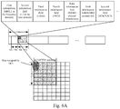
- a first scenario in this scenario, the base station currently schedules only one UE, and allocates for the UE transmission resources occupying L1 RUs in the frequency domain, and L2 OFDM symbols in the time domain.
- the information fields are composed, and the resources are indicated, in the DCI as illustrated in Fig. 6A .
- the base station transmits DCI in a PDCCH in a downlink TTI in a sub-frame, where the DCI indicates the scheduled UE, and the transmission resources allocated for the UE in the downlink TTI.
- the DCI includes a first information field indicating L1 RUs, a second information field indicating L2 OFDM symbols, a third information field indicating the ID of the scheduled UE, a fourth information field indicating a modulation and coding level for the UE, a fifth information field indicating channel information of the UE, a sixth information field indicating the current HARQ process ID of the UE, and a seventh information field indicating UL HARQ feedback.
- the UE determines upon reception of the DCI that a UE ID carried in the third information field is the same as the UE ID of the UE, according to the UE ID in the third information field, then the UE will determine that it is scheduled, and determine the time-frequency resource positions occupied by a data region according to indication information carried in the first information field (the quantity of RUs is L1), and indication information carried in the second information field (the quantity of OFDM symbols is L2); and further transmit or receive data in the determined data region according to the MCS indicated in the fourth information field, and the channel information indicated in the fifth information field. Furthermore for downlink data transmission, the UE can further make ACK/NACK feedback according to the HARQ process ID indicated in the sixth information field in the DCI, and make a UL HARQ according to ACK/NACK information indicated in the seventh information field.
- a control channel occupies the RU #0 (i.e., the first RU) in the frequency domain, and the OFDM symbol #0 (i.e., the first OFDM symbol) in the time domain, so the time-frequency positions occupied by the data region include: the RUs with the indexes of 0 to L1-1, i.e., L1 RUs in total, among the RUs occupied in the frequency domain; and the OFDM symbols with the indexes of 0 to L2-1, i.e., L2 OFDM symbols in total, among the OFDM symbols occupied in the time domain.
- the UE can determine the particular positions of the resources over which the data are transmitted, according to the start position information, and resource size information.
- DCI sent by the base station in another example can be as illustrated in Fig. 6B .
- the DCI as illustrated in Fig. 6B is different from the DCI as illustrated in Fig. 6A in an additional eighth information field indicating a type of service, and/or a type of transmission, where this information field can indicate the type of service, and/or the type of transmission of the current base station.
- the RUs in the example above can be replaced with RBs, that is, the first information field indicates the quantity of RBs occupied by the data resource scheduled by the DCI.
- a second scenario in this scenario, the base station currently schedules a group of UEs (e.g. three UEs, such as a UE1, a UE2, and a UE3 respectively), and allocates for the UEs transmission resources occupying L1 RUs in the frequency domain, and L2 OFDM symbols in the time domain.
- the information fields are composed, and the resources are indicated, in the DCI as illustrated in Fig. 7A .
- the base station transmits DCI in a PDCCH in a downlink TTI in a sub-frame, where the DCI indicates the three scheduled UEs, and the transmission resources allocated for these UEs in the downlink TTI.
- the DCI includes a first information field indicating L1 RUs, a second information field indicating L2 OFDM symbols, a third information field indicating the IDs of the scheduled UE1, UE2, and UE3, a fourth information field indicating respective modulation and coding levels for the three UEs, a fifth information field indicating respective channel information of the three UEs, a sixth information field indicating respective HARQ process IDs of the three UEs, and a seventh information field indicating respective UL HARQ feedback information of the three UEs, where the information in the respective information fields corresponds to each other in a sequential mapping order, and for example, the UE1 ID in the third information field corresponds to the first MCS indication information in the fourth information field, to the first channel information in the fifth information
- a UE determines upon reception of the DCI that a UE ID carried in the third information field is the same as the UE ID of the UE, according to the UE IDs in the third information field, then the UE will determine that it is scheduled, and the UE will determine the time-frequency resource positions occupied by a data region according to indication information carried in the first information field (the quantity of RUs is L1), and indication information carried in the second information field (the quantity of OFDM symbols is L2) with reference to an RU including a control channel; and further transmit or receive data in the determined data region according to the MCSs indicated in the fourth information field, and the channel information indicated in the fifth information field. Furthermore for downlink data transmission, the UE can further make ACK/NACK feedback according to the HARQ process IDs indicated in the sixth information field in the DCI, and make a UL HARQ according to ACK/NACK information indicated in the seventh information field.
- the control channel occupies the RU #0 (i.e., the first RU) in the frequency domain, and the OFDM symbol #0 (i.e., the first OFDM symbol) in the time domain, so the time-frequency positions occupied by the data region include: the RUs with the indexes of 0 to L1-1, i.e., L1 RUs in total, among the RUs occupied in the frequency domain; and the OFDM symbols with the indexes of 0 to L2-1, i.e., L2 OFDM symbols in total, among the OFDM symbols occupied in the time domain.
- the UE1, UE2 and UE3 are scheduled by the base station to perform MIMO transmission over the time-frequency resources.
- the UEs can determine the particular positions of the resources over which the data are transmitted, according to the start position information, and resource size information.
- DCI sent by the base station in another example can be as illustrated in Fig. 7B .
- the DCI as illustrated in Fig. 7B is different from the DCI as illustrated in Fig. 7A in an additional eighth information field indicating a type of service, and/or a type of transmission, where this information field can indicate the type of service, and/or the type of transmission of the current base station.
- the RUs in the example above can be replaced with RBs, that is, the first information field indicates the quantity of RBs occupied by the data resource scheduled by the DCI.
- a third scenario in this scenario, the base station currently schedules a group of UEs (e.g. three UEs, such as a UE1, a UE2, and a UE3 respectively), and there are similar channel conditions, and types of services for this group of UEs.
- the base station allocates for the UEs transmission resources occupying L1 RUs in the frequency domain, and L2 OFDM symbols in the time domain.
- the information fields are composed, and the resources are indicated, in the DCI as illustrated in Fig. 8A .
- the base station transmits DCI in a PDCCH in a downlink TTI in a sub-frame, where the DCI indicates the three scheduled UEs, and the transmission resources allocated for these UEs in the downlink TTI.
- the DCI includes a first information field indicating L1 RUs, a second information field indicating L2 OFDM symbols, a third information field indicating the IDs of the scheduled UE1, UE2, and UE3, a fourth information field indicating a modulation and coding level common to the three UEs, a fifth information field indicating channel information common to the three UEs, a sixth information field indicating respective HARQ process IDs of the three UEs, and a seventh information field indicating respective UL HARQ feedback information of the three UEs, where the information in the respective information fields correspond to each other in a sequential mapping order, and for example, the UE1 ID in the third information field corresponds the first HARQ process ID in the sixth information field, and the first ACK/NACK
- an additional ninth information field can be added to the DCI to indicate whether a group of UEs need to be equally allocated with a data region indicated in the DCI, where said information field can be a 1-bit information field. For example, when a value of indication information in the ninth information field is 1, these three scheduled UEs are equally allocated with the data region indicated in the DCI, i.e., equally allocated in the time domain or in the frequency domain.
- a UE determines upon reception of the DCI that a UE ID carried in the third information field is the same as the UE ID of the UE, according to the UE IDs in the third information field, then the UE will determine that it is scheduled, and the UE will determine the time-frequency resource positions occupied by the data region according to indication information carried in the first information field (the quantity of RUs is L1), indication information carried in the second information field (the quantity of OFDM symbols is L2), and information indicated in the ninth information field with reference to an RU including a control channel; and further transmit or receive data in the determined data region according to the MCS indicated in the fourth information field, and the channel information indicated in the fifth information field. Furthermore for downlink data transmission, the UE can further make ACK/NACK feedback according to the HARQ process IDs indicated in the sixth information field in the DCI, and make a UL HARQ according to ACK/NACK information indicated in the seventh information field.
- the control channel occupies the RU #0 (i.e., the first RU) in the frequency domain, and the OFDM symbol #0 (i.e., the first OFDM symbol) in the time domain, so the time-frequency positions occupied by the data region include: the RUs with the indexes of 0 to L1-1, i.e., L1 RUs in total, among the RUs occupied in the frequency domain; and the OFDM symbols with the indexes of 0 to L2-1, i.e., L2 OFDM symbols in total, among the OFDM symbols occupied in the time domain.
- the UE can determine the particular positions of the resources over which the data are transmitted, according to the start position information, and resource size information.
- DCI sent by the base station in another example can be as illustrated in Fig. 8B .
- the DCI as illustrated in Fig. 8B is different from the DCI as illustrated in Fig. 8A in an additional eighth information field indicating a type of service, and/or a type of transmission, where this information field can indicate the type of service, and/or the type of transmission of the current base station.
- the RUs in the example above can be replaced with RBs, that is, the first information field indicates the quantity of RBs occupied by the data resource scheduled by the DCI.
- an embodiment of the invention further provides a base station, which can perform the function of transmitting DCI at the network side as described in the embodiments above.
- the base station can include a sending module 902; and in a particular implementation, the base station can further include an allocating module 901 and/or a transmitting module 903, where their relationships can be as follows.
- the allocating module 901 is configured to allocate transmission resources for N scheduled users.
- the sending module 902 is configured to transmit DCI, where the DCI includes at least one or more of following information fields: a first information field indicating a frequency resource occupied by a data resource scheduled by the DCI, a second information field indicating a time resource occupied by the data resource scheduled by the DCI, and a third information field indicating the N scheduled users, where N is an integer greater than or equal to 1.
- the DCI can include the first information field indicating a size of the frequency resource occupied by the data resource scheduled by the DCI, and for example, the information field can indicate a size of an occupied resource, or a position and a size of an occupied resource, etc.; and the second information field indicating a size of the time resource occupied by the data resource scheduled by the DCI.
- the transmitting module 903 is configured to transmit data with the N scheduled users over allocated transmission resources.
- the frequency resource occupied by the data resource scheduled by the DCI includes: the quantity of resource blocks occupied by the data resource scheduled by the DCI; or the quantity of resource blocks occupied by the data resource scheduled by the DCI, and a resource start position of the resource blocks; or the quantity of resource elements occupied by the data resource scheduled by the DCI; or the quantity of resource elements occupied by the data resource scheduled by the DCI, and a start index of the resource elements; or the quantity of sub-carriers occupied by the data resource scheduled by the DCI; or the quantity of sub-carriers occupied by the data resource scheduled by the DCI, and a start index of the sub-carriers.
- the time resource occupied by the data resource scheduled by the DCI includes: the quantity of symbols occupied by the data resource scheduled by the DCI; or the quantity of symbols occupied by the data resource scheduled by the DCI, and a start symbol index of the symbols; or a length of a Transmission Time Interval (TTI) for data transmission scheduled by the DCI; or a length of a Transmission Time Interval (TTI) for data transmission scheduled by the DCI, and a time domain start position of the data transmission.
- TTI Transmission Time Interval
- TTI Transmission Time Interval
- the third information field indicates user IDs of the N scheduled users.
- the DCI further includes one or any combination of the following information fields: a fourth information field indicating a Modulation and Coding Scheme (MCS), or a group of MCSs; a fifth information field indicating a piece of or a group of pieces of multi-input multi-output channel information; a sixth information field indicating an HARQ process ID or a group of HARQ process IDs; a seventh information field indicating a piece of or a group of pieces of ACK/NACK information of an HARQ; or an eighth information field indicating a type of transmission and/or a type of service.
- MCS Modulation and Coding Scheme
- the seventh information field can exist in DCI for scheduling uplink transmission.
- the downlink control information further includes a ninth information field, wherein the ninth information field indicates whether a group of scheduled users are equally allocated with a time-frequency resource region indicated by the first information field and the second information field in the DCI, where equal allocation refers to equal allocation in the time domain or in the frequency domain.
- an embodiment of the invention further provides a UE, which can perform the function of transmitting DCI at the UE side as described in the embodiments above.
- the UE can include a receiving module 1001; and in a particular implementation, the UE can further include a transmitting module 1002, where their relationships can be as follows.
- the receiving module 1001 is configured to receive DCI, where the DCI includes at least one or more of following information fields: a first information field indicating a frequency resource occupied by a data resource scheduled by the DCI, a second information field indicating a time resource occupied by the data resource scheduled by the DCI, and a third information field indicating N scheduled users, where N is an integer greater than or equal to 1; and the transmitting module 1002 is configured to receive or transmit data over an allocated transmission resource.
- the DCI can include the first information field indicating a size of the frequency resource occupied by the data resource scheduled by the DCI, and for example, the information field can indicate a size of an occupied resource, a position and a size of an occupied resource, etc.; and the second information field indicating a size of the time resource occupied by the data resource scheduled by the DCI.
- the frequency resource occupied by the data resource scheduled by the DCI includes: the quantity of resource blocks occupied by the data resource scheduled by the DCI; or the quantity of resource blocks occupied by the data resource scheduled by the DCI, and a resource start position of the resource blocks; or the quantity of resource elements occupied by the data resource scheduled by the DCI; or the quantity of resource elements occupied by the data resource scheduled by the DCI, and a start index of the resource elements; or the quantity of sub-carriers occupied by the data resource scheduled by the DCI; or the quantity of sub-carriers occupied by the data resource scheduled by the DCI, and a start index of the sub-carriers.
- the time resource occupied by the data resource scheduled by the DCI includes: the quantity of symbols occupied by the data resource scheduled by the DCI; or the quantity of symbols occupied by the data resource scheduled by the DCI, and a start symbol index of the symbols; or a length of a Transmission Time Interval (TTI) for data transmission scheduled by the DCI; or a length of a Transmission Time Interval (TTI) for data transmission scheduled by the DCI, and a time domain start position of the data transmission.
- TTI Transmission Time Interval
- TTI Transmission Time Interval
- the third information field indicates user IDs of the N scheduled users.
- the DCI further includes one or any combination of the following information fields: a fourth information field indicating a Modulation and Coding Scheme (MCS), or a group of MCSs; a fifth information field indicating a piece of or a group of pieces of multi-input multi-output channel information; a sixth information field indicating an HARQ process ID or a group of HARQ process IDs; a seventh information field indicating a piece of or a group of pieces of ACK/NACK information of an HARQ; or an eighth information field indicating a type of transmission and/or a type of service.
- MCS Modulation and Coding Scheme
- the seventh information field can exist in DCI for scheduling uplink transmission.
- the DCI further includes a ninth information field, where the ninth information field indicates whether a group of scheduled users are equally allocated with a time-frequency resource region indicated by the first information field and the second information field in the DCI, where equal allocation refers to equal allocation in the time domain or in the frequency domain.
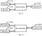
- an embodiment of the invention further provides a base station, which can perform the function of transmitting DCI at the network side as described in the embodiments above.
- the base station can include a processor 1101, a memory 1102, a transceiver 1103, and a bus interface, where: the processor 1101 is responsible for managing bus architecture and performing normal processes, and the memory 1102 can store data for use by the processor 1101 in performing operations.
- the transceiver 1103 is configured to receive and transmit data under the control of the processor 1101.
- the bus architecture can include any quantity of interconnecting buses and bridges to particularly link together various circuits including one or more processors represented by the processor 1101, and one or more memories represented by the memory 1102.
- the bus architecture can further link together various other circuits, e.g., a peripheral device, a manostat, a power management circuit, etc., all of which are well known in the art, so a further description thereof will be omitted in this context.
- the bus interface serves as an interface.
- the processor 1101 is responsible for managing the bus architecture and performing normal processes, and the memory 1102 can store data for use by the processor 1101 in performing operations.
- the flow of processing a signal according to the embodiment of the invention can be applied to the processor 1101, or performed by the processor 1101.
- the respective operations in the flow of processing a signal can be performed by integrated logic circuits in hardware, or instructions in software, in the processor 1101.
- the processor 1101 can be a general-purpose processor, a digital signal processor, an application specific integrated circuit, a field programmable gate array, or another programmable logic device, discrete gate, transistor logic device, or discrete hardware component.
- the respective methods, operations, and logic block diagrams disclosed in the embodiments of the invention can be implemented or performed by the processor 1101.
- the general-purpose processor can be a micro-processor, or can be any conventional processor, etc.
- the operations in the method according to the embodiment of the invention can be performed directly by a hardware processor, or performed by a combination of hardware and software modules in the processor.
- the software module can be located in a random memory, a flash memory, a read-only memory, a programmable read-only memory, an electrically erasable and programmable memory, a register, or another storage medium known in the art.
- the storage medium is located in the memory 1102, and the processor 1101 reads the information in the memory 1102, and performs the operations in the flow of processing a signal, in combination with the hardware thereof.
- the processor 1101 is configured to read and execute programs in the memory 1102 to: transmit DCI, where the DCI includes at least one or more of the following information fields: a first information field indicating a frequency resource occupied by a data resource scheduled by the DCI, a second information field indicating a time resource occupied by the data resource scheduled by the DCI, and a third information field indicating N scheduled users, where N is an integer greater than or equal to 1.
- the DCI can include the first information field indicating a size of the frequency resource occupied by the data resource scheduled by the DCI, and for example, the information field can indicate a size of an occupied resource, or a position and a size of an occupied resource, etc.; and the second information field indicating a size of the time resource occupied by the data resource scheduled by the DCI.
- the frequency resource occupied by the data resource scheduled by the DCI includes: the quantity of resource blocks occupied by the data resource scheduled by the DCI; or the quantity of resource blocks occupied by the data resource scheduled by the DCI, and a resource start position of the resource blocks; or the quantity of resource elements occupied by the data resource scheduled by the DCI; or the quantity of resource elements occupied by the data resource scheduled by the DCI, and a start index of the resource elements; or the quantity of sub-carriers occupied by the data resource scheduled by the DCI; or the quantity of sub-carriers occupied by the data resource scheduled by the DCI, and a start index of the sub-carriers.
- the time resource occupied by the data resource scheduled by the DCI includes: the quantity of symbols occupied by the data resource scheduled by the DCI; or the quantity of symbols occupied by the data resource scheduled by the DCI, and a start symbol index of the symbols; or a length of a Transmission Time Interval (TTI) for data transmission scheduled by the DCI; or a length of a Transmission Time Interval (TTI) for data transmission scheduled by the DCI, and a time domain start position of the data transmission.
- TTI Transmission Time Interval
- TTI Transmission Time Interval
- the third information field indicates user IDs of the N scheduled users.
- the DCI further includes one or any combination of the following information fields: a fourth information field indicating a Modulation and Coding Scheme (MCS), or a group of MCSs; a fifth information field indicating a piece of or a group of pieces of multi-input multi-output channel information; a sixth information field indicating an HARQ process ID or a group of HARQ process IDs; a seventh information field indicating a piece of or a group of pieces of ACK/NACK information of an HARQ; or an eighth information field indicating a type of transmission and/or a type of service.
- MCS Modulation and Coding Scheme
- the seventh information field can exist in DCI for scheduling uplink transmission.
- the DCI further includes a ninth information field, where the ninth information field indicates whether a group of scheduled users are equally allocated with a time-frequency resource region indicated by the first information field and the second information field in the DCI, where equal allocation refers to equal allocation in the time domain or in the frequency domain.
- the processor 1101 can be further configured to allocate transmission resources for the N scheduled users before the DCI is transmitted.
- the processor 1101 can be further configured to transmit data with the N scheduled users over allocated transmission resources after the DCI is transmitted.
- an embodiment of the invention further provides a UE, which can perform the function of transmitting DCI at the UE side as described in the embodiments above.
- the UE can include a processor 1201, a memory 1202, a transceiver 1203, and a bus interface, where: the processor 1201 is responsible for managing bus architecture and performing normal processes, and the memory 1202 can store data for use by the processor 1201 in performing operations.
- the transceiver 1203 is configured to receive and transmit data under the control of the processor 1201.
- the bus architecture can include any quantity of interconnecting buses and bridges to particularly link together various circuits including one or more processors represented by the processor 1201, and one or more memories represented by the memory 1202.
- the bus architecture can further link together various other circuits, e.g., a peripheral device, a manostat, a power management circuit, etc., all of which are well known in the art, so a further description thereof will be omitted in this context.
- the bus interface serves as an interface.
- the processor 1201 is responsible for managing the bus architecture and performing normal processes, and the memory 1202 can store data for use by the processor 1201 in performing operations.
- the flow of processing a signal according to the embodiment of the invention can be applied to the processor 1201, or performed by the processor 1201.
- the respective operations in the flow of processing a signal can be performed by integrated logic circuits in hardware, or instructions in software, in the processor 1201.
- the processor 1201 can be a general-purpose processor, a digital signal processor DSP, an application specific integrated circuit, a field programmable gate array, or another programmable logic device, discrete gate, transistor logic device, or discrete hardware component.
- the respective methods, operations, and logic block diagrams disclosed in the embodiments of the invention can be implemented or performed by the processor 1201.
- the general-purpose processor can be a micro-processor, or can be any conventional processor, etc.
- the operations in the method according to the embodiment of the invention can be performed directly by a hardware processor, or performed by a combination of hardware and software modules in the processor.
- the software module can be located in a random memory, a flash memory, a read-only memory, a programmable read-only memory, an electrically erasable and programmable memory, a register, or another storage medium known in the art.
- the storage medium is located in the memory 1202, and the processor 1201 reads the information in the memory 1202, and performs the operations in the flow of processing a signal, in combination with the hardware thereof.
- the processor 1201 is configured to read and execute programs in the memory 1202 to: receive DCI, where the DCI includes at least one or more of the following information fields: a first information field indicating a frequency resource occupied by a data resource scheduled by the DCI, a second information field indicating a time resource occupied by the data resource scheduled by the DCI, and a third information field indicating N scheduled users, where N is an integer greater than or equal to 1.
- the DCI can include the first information field indicating a size of the frequency resource occupied by the data resource scheduled by the DCI, and for example, the information field can indicate a size of an occupied resource, or a positions and a size of an occupied resource, etc.; and the second information field indicating a size of the time resource occupied by the data resource scheduled by the DCI.
- the frequency resource occupied by the data resource scheduled by the DCI includes: the quantity of resource blocks occupied by the data resource scheduled by the DCI; or the quantity of resource blocks occupied by the data resource scheduled by the DCI, and a resource start position of the resource blocks; or the quantity of resource elements occupied by the data resource scheduled by the DCI; or the quantity of resource elements occupied by the data resource scheduled by the DCI, and a start index of the resource elements; or the quantity of sub-carriers occupied by the data resource scheduled by the DCI; or the quantity of sub-carriers occupied by the data resource scheduled by the DCI, and a start index of the sub-carriers.
- the time resource occupied by the data resource scheduled by the DCI includes: the quantity of symbols occupied by the data resource scheduled by the DCI; or the quantity of symbols occupied by the data resource scheduled by the DCI, and a start symbol index of the symbols; or a length of a Transmission Time Interval (TTI) for data transmission scheduled by the DCI; or a length of a Transmission Time Interval (TTI) for data transmission scheduled by the DCI, and a time domain start position of the data transmission.
- TTI Transmission Time Interval
- TTI Transmission Time Interval
- the third information field indicates user IDs of the N scheduled users.
- the DCI further includes one or any combination of the following information fields: a fourth information field indicating a Modulation and Coding Scheme (MCS), or a group of MCSs; a fifth information field indicating a piece of or a group of pieces of multi-input multi-output channel information; a sixth information field indicating an HARQ process ID or a group of HARQ process IDs; a seventh information field indicating a piece of or a group of pieces of ACK/NACK information of an HARQ; or an eighth information field indicating a type of transmission and/or a type of service.
- MCS Modulation and Coding Scheme
- the seventh information field can exist in DCI for scheduling uplink transmission.
- the DCI further includes a ninth information field, where the ninth information field indicates whether a group of scheduled users are equally allocated with a time-frequency resource region indicated by the first information field and the second information field in the DCI, where equal allocation refers to equal allocation in the time domain or in the frequency domain.
- processor 1201 can be further configured to receive or transmit data over an allocated transmission resource after the downlink control information is received.
- These computer program instructions can also be stored into a computer readable memory capable of directing the computer or the other programmable data processing device to operate in a specific manner so that the instructions stored in the computer readable memory create an article of manufacture including instruction means which perform the functions specified in the flow(s) of the flow chart and/or the block(s) of the block diagram.
- These computer program instructions can also be loaded onto the computer or the other programmable data processing device so that a series of operational steps are performed on the computer or the other programmable data processing device to create a computer implemented process so that the instructions executed on the computer or the other programmable device provide operations for performing the functions specified in the flow(s) of the flow chart and/or the block(s) of the block diagram.
Landscapes
- Engineering & Computer Science (AREA)
- Signal Processing (AREA)
- Computer Networks & Wireless Communication (AREA)
- Quality & Reliability (AREA)
- Mobile Radio Communication Systems (AREA)
Claims (12)
- Verfahren zum Übertragen von Downlink-Steuerinformationen, DCI (Downlink Control Information), wobei das Verfahren umfasst:das Übertragen (402) der DCI, wobei die DCI umfassen: ein erstes Informationsfeld, das eine Frequenzressource angibt, die durch eine Datenressource belegt ist, die durch die DCI geplant ist, und ein zweites Informationsfeld, das eine Zeitressource angibt, die durch die Datenressource belegt ist, die durch die DCI geplant ist;wobei die Zeitressource, die durch die Datenressource belegt ist, die durch die DCI geplant ist, aufweist:eine Menge von Symbolen, die durch die Datenressource belegt sind, die durch die DCI geplant ist; odereine Menge von Symbolen, die durch die Datenressource belegt sind, die durch die DCI geplant ist, und einen Startsymbolindex der Symbole; odereine Länge eines Übertragungszeitintervalls, TTI (Transmission Time Interval), für eine Datenübertragung, die durch die DCI geplant ist; odereine Länge eines Übertragungszeitintervalls, TTI, für eine Datenübertragung, die durch die DCI geplant ist, und eine Zeitbereichstartposition der Datenübertragung.
- Verfahren nach Anspruch 1, wobei die Frequenzressource, die durch die Datenressource belegt ist, die durch die DCI geplant ist, aufweist:eine Menge von Ressourcenblöcken, die durch die Datenressource belegt sind, die durch die DCI geplant ist; odereine Menge von Ressourcenblöcken, die durch die Datenressource belegt sind, die durch die DCI geplant ist, und eine Ressourcenstartposition der Ressourcenblöcke; odereine Menge von Ressourcenelementen, die durch die Datenressource belegt sind, die durch die DCI geplant ist; odereine Menge von Ressourcenelementen, die durch die Datenressource belegt sind, die durch die DCI geplant ist, und einen Startindex der Ressourcenelemente; odereine Menge von Unterträgern, die durch die Datenressource belegt sind, die durch die DCI geplant ist; odereine Menge von Unterträgern, die durch die Datenressource belegt sind, die durch die DCI geplant ist, und einen Startindex der Unterträger.
- Verfahren nach Anspruch 1, wobei die DCI ferner ein drittes Informationsfeld umfassen, das N geplante Benutzer angibt, wobei N eine ganze Zahl größer oder gleich 1 ist;
wobei, bevor die DCI übertragen werden, das Verfahren ferner umfasst: das Zuweisen (401) von Übertragungsressourcen für die N geplanten Benutzer durch eine Basisstation; und/oder
nachdem die DCI übertragen werden, das Verfahren ferner umfasst: das Übertragen (403) von Daten mit den N geplanten Benutzern über zugewiesene Übertragungsressourcen durch eine Basisstation. - Verfahren nach einem der Ansprüche 1 bis 3, wobei die DCI ferner eine oder jegliche Kombination der folgenden Informationsfelder umfassen:ein viertes Informationsfeld, das ein MCS (Modulation and Coding Scheme) oder eine Gruppe von MCS angibt;ein fünftes Informationsfeld, das einen Teil von oder eine Gruppe von Teilen von Multi-Input-Multi-Output-Kanalinformationen angibt;ein sechstes Informationsfeld, das eine HARQ-(Hybrid Automatic Repeated Request)-Prozesskennung oder eine Gruppe von HARQ-Prozesskennungen angibt;ein siebtes Informationsfeld, das einen Teil von oder eine Gruppe von Teilen von ACK/NACK-(Acknowledgement/Non-Acknowledgement)-Informationen einer Uplink-HARQ (Hybrid Automatic Repeated Request) angibt;ein achtes Informationsfeld, das eine Art der Übertragung und/oder eine Art des Dienstes angibt; oderein neuntes Informationsfeld, das angibt, ob eine Gruppe geplanter Benutzer gleichmäßig mit einem Zeit-Frequenz-Ressourcenbereich, der durch das erste Informationsfeld und das zweite Informationsfeld in den DCI angegeben ist, zugewiesen ist, wobei sich gleichmäßige Zuweisung auf gleichmäßige Zuweisung in einem Zeitbereich oder in einem Frequenzbereich bezieht;wobei das siebte Informationsfeld in DCI für das Planen einer Uplink-Übertragung existiert.
- Verfahren zum Übertragen von Downlink-Steuerinformationen, DCI, wobei das Verfahren umfasst:das Empfangen (501) der DCI, wobei die DCI umfassen: ein erstes Informationsfeld, das eine Frequenzressource angibt, die durch eine Datenressource belegt ist, die durch die DCI geplant ist, und ein zweites Informationsfeld, das eine Zeitressource angibt, die durch die Datenressource belegt ist, die durch die DCI geplant ist;wobei die Zeitressource, die durch die Datenressource belegt ist, die durch die DCI geplant ist, aufweist:eine Menge von Symbolen, die durch die Datenressource belegt sind, die durch die DCI geplant ist; odereine Menge von Symbolen, die durch die Datenressource belegt sind, die durch die DCI geplant ist, und einen Startsymbolindex der Symbole; odereine Länge eines Übertragungszeitintervalls, TTI (Transmission Time Interval), für eine Datenübertragung, die durch die DCI geplant ist; odereine Länge eines Übertragungszeitintervalls, TTI, für eine Datenübertragung, die durch die DCI geplant ist, und eine Zeitbereichstartposition der Datenübertragung.
- Verfahren nach Anspruch 5, wobei die Frequenzressource, die durch die Datenressource belegt ist, die durch die DCI geplant ist, aufweist:eine Menge von Ressourcenblöcken, die durch die Datenressource belegt sind, die durch die DCI geplant ist; odereine Menge von Ressourcenblöcken, die durch die Datenressource belegt sind, die durch die DCI geplant ist, und eine Ressourcenstartposition der Ressourcenblöcke; odereine Menge von Ressourcenelementen, die durch die Datenressource belegt sind, die durch die DCI geplant ist; odereine Menge von Ressourcenelementen, die durch die Datenressource belegt sind, die durch die DCI geplant ist, und einen Startindex der Ressourcenelemente; odereine Menge von Unterträgern, die durch die Datenressource belegt sind, die durch die DCI geplant ist; odereine Menge von Unterträgern, die durch die Datenressource belegt sind, die durch die DCI geplant ist, und einen Startindex der Unterträger.
- Verfahren nach Anspruch 5, wobei die DCI ferner ein drittes Informationsfeld umfassen, das N geplante Benutzer angibt, wobei N eine ganze Zahl größer oder gleich 1 ist;
wobei, nachdem die DCI empfangen werden, das Verfahren ferner umfasst: das Empfangen oder Übertragen (502) von Daten über eine Übertragungsressource, die durch die Basisstation zugewiesen wird. - Verfahren nach einem der Ansprüche 5 bis 7, wobei die DCI ferner eine oder jegliche Kombination der folgenden Informationsfelder umfassen:ein viertes Informationsfeld, das ein MCS (Modulation and Coding Scheme) oder eine Gruppe von MCS angibt;ein fünftes Informationsfeld, das einen Teil von oder eine Gruppe von Teilen von Multi-Input-Multi-Output-Kanalinformationen angibt;ein sechstes Informationsfeld, das eine HARQ-(Hybrid Automatic Repeated Request)-Prozesskennung oder eine Gruppe von HARQ-Prozesskennungen angibt;ein siebtes Informationsfeld, das einen Teil von oder eine Gruppe von Teilen von ACK/NACK-(Acknowledgement/Non-Acknowledgement)-Informationen einer Uplink-HARQ (Hybrid Automatic Repeated Request) angibt;ein achtes Informationsfeld, das eine Art der Übertragung und/oder eine Art des Dienstes angibt; oderein neuntes Informationsfeld, das angibt, ob eine Gruppe geplanter Benutzer gleichmäßig mit einem Zeit-Frequenz-Ressourcenbereich, der durch das erste Informationsfeld und das zweite Informationsfeld in den DCI angegeben ist, zugewiesen ist, wobei sich gleichmäßige Zuweisung auf gleichmäßige Zuweisung in einem Zeitbereich oder in einem Frequenzbereich bezieht;wobei das siebte Informationsfeld in DCI für das Planen einer Uplink-Übertragung existiert.
- Basisstation, wobei die Basisstation aufweist:ein Sendemodul (902), das dazu ausgebildet ist, Downlink-Steuerinformationen, DCI, zu übertragen, wobei die DCI umfassen: ein erstes Informationsfeld, das eine Frequenzressource angibt, die durch eine Datenressource belegt ist, die durch die DCI geplant ist, und ein zweites Informationsfeld, das eine Zeitressource angibt, die durch die Datenressource belegt ist, die durch die DCI geplant ist;wobei die Zeitressource, die durch die Datenressource belegt ist, die durch die DCI geplant ist, aufweist:eine Menge von Symbolen, die durch die Datenressource belegt sind, die durch die DCI geplant ist; odereine Menge von Symbolen, die durch die Datenressource belegt sind, die durch die DCI geplant ist, und einen Startsymbolindex der Symbole; odereine Länge eines Übertragungszeitintervalls, TTI (Transmission Time Interval), für eine Datenübertragung, die durch die DCI geplant ist; odereine Länge eines Übertragungszeitintervalls, TTI, für eine Datenübertragung, die durch die DCI geplant ist, und eine Zeitbereichstartposition der Datenübertragung.
- Basisstation nach Anspruch 9, wobei die Frequenzressource, die durch die Datenressource belegt ist, die durch die DCI geplant ist, aufweist:eine Menge von Ressourcenblöcken, die durch die Datenressource belegt sind, die durch die DCI geplant ist; odereine Menge von Ressourcenblöcken, die durch die Datenressource belegt sind, die durch die DCI geplant ist, und eine Ressourcenstartposition der Ressourcenblöcke; odereine Menge von Ressourcenelementen, die durch die Datenressource belegt sind, die durch die DCI geplant ist; odereine Menge von Ressourcenelementen, die durch die Datenressource belegt sind, die durch die DCI geplant ist, und einen Startindex der Ressourcenelemente; odereine Menge von Unterträgern, die durch die Datenressource belegt sind, die durch die DCI geplant ist; odereine Menge von Unterträgern, die durch die Datenressource belegt sind, die durch die DCI geplant ist, und einen Startindex der Unterträger.
- Basisstation nach Anspruch 9, wobei die DCI ferner ein drittes Informationsfeld umfassen, das N geplante Benutzer angibt, wobei N eine ganze Zahl größer oder gleich 1 ist;
wobei die Basisstation ferner aufweist:ein zuweisendes Modul (901), das dazu ausgebildet ist, Übertragungsressourcen für die N geplanten Benutzer zuzuweisen, bevor die DCI übertragen werden; und/oderein übertragendes Modul (903), das dazu ausgebildet ist, Daten mit den N geplanten Benutzern über zugewiesene Übertragungsressourcen zu übertragen, nachdem die DCI übertragen werden. - Basisstation nach einem der Ansprüche 9 bis 11, wobei die DCI ferner eine oder jegliche Kombination der folgenden Informationsfelder umfassen:ein viertes Informationsfeld, das ein MCS (Modulation and Coding Scheme) oder eine Gruppe von MCS angibt;ein fünftes Informationsfeld, das einen Teil von oder eine Gruppe von Teilen von Multi-Input-Multi-Output-Kanalinformationen angibt;ein sechstes Informationsfeld, das eine HARQ-(Hybrid Automatic Repeated Request)-Prozesskennung oder eine Gruppe von HARQ-Prozesskennungen angibt;ein siebtes Informationsfeld, das einen Teil von oder eine Gruppe von Teilen von ACK/NACK-(Acknowledgement/Non-Acknowledgement)-Informationen einer Uplink-HARQ (Hybrid Automatic Repeated Request) angibt;ein achtes Informationsfeld, das eine Art der Übertragung und/oder eine Art des Dienstes angibt; oderein neuntes Informationsfeld, das angibt, ob eine Gruppe geplanter Benutzer gleichmäßig mit einem Zeit-Frequenz-Ressourcenbereich, der durch das erste Informationsfeld und das zweite Informationsfeld in den DCI angegeben ist, zugewiesen ist, wobei sich gleichmäßige Zuweisung auf gleichmäßige Zuweisung in einem Zeitbereich oder in einem Frequenzbereich bezieht;wobei das siebte Informationsfeld in DCI für das Planen einer Uplink-Übertragung existiert.
Applications Claiming Priority (3)
| Application Number | Priority Date | Filing Date | Title |
|---|---|---|---|
| CN201610074559 | 2016-02-02 | ||
| CN201610125584.4A CN107027184B (zh) | 2016-02-02 | 2016-03-04 | 一种下行控制信息传输方法及装置 |
| PCT/CN2017/071800 WO2017133479A1 (zh) | 2016-02-02 | 2017-01-20 | 一种下行控制信息传输方法及装置 |
Publications (3)
| Publication Number | Publication Date |
|---|---|
| EP3404979A1 EP3404979A1 (de) | 2018-11-21 |
| EP3404979A4 EP3404979A4 (de) | 2019-02-20 |
| EP3404979B1 true EP3404979B1 (de) | 2020-07-22 |
Family
ID=59524356
Family Applications (1)
| Application Number | Title | Priority Date | Filing Date |
|---|---|---|---|
| EP17746799.0A Active EP3404979B1 (de) | 2016-02-02 | 2017-01-20 | Verfahren und vorrichtung zur übertragung von downlink-steuerinformationen |
Country Status (5)
| Country | Link |
|---|---|
| US (2) | US11382123B2 (de) |
| EP (1) | EP3404979B1 (de) |
| JP (1) | JP6630838B2 (de) |
| KR (1) | KR102219746B1 (de) |
| CN (1) | CN107027184B (de) |
Families Citing this family (39)
| Publication number | Priority date | Publication date | Assignee | Title |
|---|---|---|---|---|
| CN110190929B (zh) * | 2016-08-12 | 2020-06-16 | 华为技术有限公司 | 数据传输的方法、装置和计算机可读存储介质 |
| CN110235397A (zh) * | 2016-12-01 | 2019-09-13 | 瑞典爱立信有限公司 | 下行链路harq反馈传输 |
| KR102288629B1 (ko) * | 2017-05-04 | 2021-08-11 | 삼성전자 주식회사 | 무선 통신 시스템에서 상향 제어 채널 전송 방법 및 장치 |
| CN109121212B (zh) * | 2017-06-24 | 2021-06-08 | 华为技术有限公司 | 数据传输方法、数据传输反馈方法和相关设备 |
| CN109525361B (zh) | 2017-09-20 | 2020-11-06 | 中国移动通信有限公司研究院 | 控制信息的传输方法、接收方法、基站及终端 |
| CN109673053B (zh) * | 2017-10-16 | 2023-08-08 | 普天信息技术有限公司 | 一种确定下行控制信道的方法及装置 |
| WO2019140588A1 (zh) * | 2018-01-18 | 2019-07-25 | Oppo广东移动通信有限公司 | 一种时域资源确定方法及装置、计算机存储介质 |
| JP7077409B2 (ja) | 2018-02-02 | 2022-05-30 | オッポ広東移動通信有限公司 | 情報伝送方法及び装置 |
| CN110139385A (zh) * | 2018-02-02 | 2019-08-16 | 中国移动通信有限公司研究院 | 一种发送下行控制信息的方法、网络设备及存储介质 |
| CN110166186B (zh) * | 2018-02-12 | 2020-11-24 | 电信科学技术研究院有限公司 | 一种确定dci中信息域取值的方法及装置 |
| US11039429B2 (en) | 2018-04-04 | 2021-06-15 | Huawei Technologies Co., Ltd. | Method and apparatus for downlink control information communication and interpretation |
| CN110417518B (zh) * | 2018-04-26 | 2022-08-26 | 华为技术有限公司 | 基于harq技术的通信方法、设备及系统 |
| JP7387642B2 (ja) * | 2018-05-11 | 2023-11-28 | テレフオンアクチーボラゲット エルエム エリクソン(パブル) | ダウンリンク制御情報(dci)のサイズ調整用のシステムおよび方法 |
| CN110677217B (zh) * | 2018-07-03 | 2021-05-11 | 电信科学技术研究院有限公司 | 一种数据传输方法及装置 |
| CN110830192B (zh) * | 2018-08-08 | 2022-08-19 | 展讯通信(上海)有限公司 | 系统消息的指示、确定方法及装置、存储介质、基站、用户设备 |
| EP4199401A1 (de) * | 2018-08-10 | 2023-06-21 | Huawei Technologies Co., Ltd. | Datenübertragungsverfahren und kommunikationsvorrichtung |
| GB2576217A (en) * | 2018-08-10 | 2020-02-12 | Nec Corp | Communication system |
| CA3098094A1 (en) * | 2018-08-23 | 2020-02-27 | Guangdong Oppo Mobile Telecommunications Corp., Ltd. | Feedback information transmission method and apparatus and communications device |
| CN110875803B (zh) * | 2018-09-01 | 2022-11-01 | 上海朗帛通信技术有限公司 | 一种被用于无线通信节点中的方法和装置 |
| CN113613331B (zh) | 2018-09-28 | 2024-05-24 | 华为技术有限公司 | 一种通信方法、装置及设备 |
| CN111107632B (zh) * | 2018-10-26 | 2022-08-05 | 大唐移动通信设备有限公司 | 一种数据传输方法及其装置 |
| CN113169818B (zh) * | 2018-12-28 | 2023-04-18 | 华为技术有限公司 | 下行控制信息处理方法、装置、终端设备及通信系统 |
| WO2020142940A1 (zh) * | 2019-01-09 | 2020-07-16 | 北京小米移动软件有限公司 | 资源分配方法及装置 |
| CN111435867B (zh) | 2019-01-11 | 2021-12-10 | 华为技术有限公司 | 上行控制信息复用的方法和装置 |
| WO2020164131A1 (zh) * | 2019-02-15 | 2020-08-20 | 华为技术有限公司 | 通信方法和装置 |
| SG11202109985UA (en) * | 2019-03-11 | 2021-10-28 | Beijing Xiaomi Mobile Software Co Ltd | Transmission indication method and apparatus |
| CN111867066B (zh) * | 2019-04-30 | 2023-04-07 | 大唐移动通信设备有限公司 | 一种信息指示和确定指示信息的方法及设备 |
| CN112188443B (zh) * | 2019-07-04 | 2022-04-12 | 华为技术有限公司 | 一种数据传输方法及通信装置 |
| JP6924226B2 (ja) * | 2019-07-11 | 2021-08-25 | シャープ株式会社 | 端末装置、基地局装置、および、通信方法 |
| WO2021056146A1 (zh) * | 2019-09-23 | 2021-04-01 | 华为技术有限公司 | 一种控制信息的传输方法、装置及系统 |
| US11582760B2 (en) * | 2019-09-25 | 2023-02-14 | Qualcomm Incorporated | Techniques for joint dynamic hybrid automatic repeat request for multiple transmission reception points |
| WO2021092841A1 (zh) | 2019-11-14 | 2021-05-20 | 北京小米移动软件有限公司 | 下行控制信息传输方法及装置、通信设备及存储介质 |
| US11595159B2 (en) * | 2020-02-13 | 2023-02-28 | Apple, Inc. | HARQ design for wireless communications |
| CN114257362B (zh) * | 2020-09-25 | 2024-09-20 | 北京紫光展锐通信技术有限公司 | 资源指示方法及相关装置 |
| KR102952979B1 (ko) * | 2020-10-15 | 2026-04-15 | 엘지전자 주식회사 | 디지털 aircomp 시그널링 |
| EP4231734B1 (de) * | 2020-10-19 | 2024-12-04 | Beijing Xiaomi Mobile Software Co., Ltd. | Verfahren und vorrichtung zum senden von hilfsressourcensätzen, verfahren und vorrichtung zum empfangen von hilfsressourcensätzen |
| CN116711429B (zh) * | 2021-05-10 | 2025-11-11 | Oppo广东移动通信有限公司 | 用于数据传输的方法、装置、设备及存储介质 |
| CN115623591B (zh) * | 2021-07-12 | 2026-04-24 | 展讯通信(上海)有限公司 | 一种指示方法及通信装置 |
| WO2023115583A1 (zh) * | 2021-12-24 | 2023-06-29 | Oppo广东移动通信有限公司 | 通信方法、终端设备和网络设备 |
Family Cites Families (28)
| Publication number | Priority date | Publication date | Assignee | Title |
|---|---|---|---|---|
| US8131306B2 (en) * | 2006-03-20 | 2012-03-06 | Intel Corporation | Wireless access network and method for allocating data subcarriers within a downlink subframe based on grouping of user stations |
| ZA200905048B (en) * | 2007-01-09 | 2010-09-29 | Sharp Kk | Base station device, mobile station device, control information transmission method, control information reception method and program |
| EP1944896A1 (de) * | 2007-01-09 | 2008-07-16 | Matsushita Electric Industrial Co., Ltd. | Konfiguration von Steuerkanälen in einem mobilen Kommunikationssystem |
| CN101272234B (zh) * | 2007-03-20 | 2011-11-23 | 中兴通讯股份有限公司 | 用于ofdm系统的数据传输方法及系统 |
| CN101568153B (zh) * | 2008-04-23 | 2012-02-01 | 电信科学技术研究院 | 一种实时小分组业务的传输方法及装置 |
| US20090276675A1 (en) * | 2008-05-05 | 2009-11-05 | Jussi Ojala | Signaling of redundancy version and new data indication |
| WO2010133043A1 (zh) * | 2009-05-22 | 2010-11-25 | 华为技术有限公司 | 多子帧调度方法、系统及终端、基站 |
| CN101801097B (zh) | 2010-01-08 | 2015-05-20 | 中兴通讯股份有限公司 | 物理上行共享信道调度信息的指示方法 |
| CN101801093A (zh) * | 2010-02-03 | 2010-08-11 | 中兴通讯股份有限公司 | 资源分配方式指示方法、装置和系统 |
| KR101684867B1 (ko) * | 2010-04-07 | 2016-12-09 | 삼성전자주식회사 | 공간 다중화 이득을 이용한 제어 정보 송수신 방법 |
| WO2013012261A2 (ko) | 2011-07-19 | 2013-01-24 | 엘지전자 주식회사 | 무선통신 시스템에서 자원 할당 정보를 송신 및 수신하는 방법과 이를 위한 장치 |
| CN103891166A (zh) * | 2011-09-30 | 2014-06-25 | 交互数字专利控股公司 | 无线通信中的多点传输 |
| US10039088B2 (en) | 2012-01-26 | 2018-07-31 | Samsung Electronics Co., Ltd. | Method and apparatus for scheduling communication for low capability devices |
| US9843429B2 (en) * | 2012-07-31 | 2017-12-12 | Lg Electronics Inc. | Method and apparatus for transmitting and receiving data |
| WO2014046458A1 (ko) * | 2012-09-20 | 2014-03-27 | 엘지전자 주식회사 | 무선 통신 시스템에서 안테나 포트 관계를 고려한 하향링크 신호 송수신 방법 및 장치 |
| WO2014129848A1 (ko) * | 2013-02-21 | 2014-08-28 | 엘지전자 주식회사 | 무선 통신 시스템에서 제어 정보를 송수신하는 방법 및 이를 위한 장치 |
| US9596056B2 (en) * | 2013-07-15 | 2017-03-14 | Lg Electronics Inc. | Method for interference cancellation in wireless communication system and apparatus therefor |
| CN104348579B (zh) * | 2013-08-05 | 2019-11-19 | 中兴通讯股份有限公司 | 下行信道时域位置确定方法和装置 |
| CN103716823B (zh) | 2013-12-23 | 2017-06-27 | 上海无线通信研究中心 | Lte/lte‑a系统中下行控制信息盲检指示发送及下行控制信息盲检方法 |
| CN103874217B (zh) | 2014-03-17 | 2017-06-13 | 大唐移动通信设备有限公司 | 在tdd‑lte系统中上行抗干扰的方法及设备 |
| KR101852708B1 (ko) * | 2014-05-08 | 2018-04-26 | 후아웨이 테크놀러지 컴퍼니 리미티드 | 리소스 스케줄링 방법, 디바이스 및 시스템 |
| CN105099634B (zh) * | 2014-05-09 | 2019-05-07 | 中兴通讯股份有限公司 | 动态资源的分配方法及装置、基站、终端 |
| US20160088594A1 (en) * | 2014-09-18 | 2016-03-24 | Gang Xiong | Device and method of supporting reduced data transmission bandwidth |
| WO2016072688A2 (ko) * | 2014-11-05 | 2016-05-12 | 엘지전자 주식회사 | Ack/nack 신호 수신 방법 및 mtc 기기 |
| US10805061B2 (en) * | 2015-07-20 | 2020-10-13 | Lg Electronics Inc. | Method and apparatus for handling MBSFN subframes for short TTI in wireless communication system |
| WO2017024563A1 (zh) * | 2015-08-12 | 2017-02-16 | 华为技术有限公司 | 一种数据传输方法、装置及系统 |
| PL3331179T3 (pl) * | 2015-12-18 | 2021-12-20 | Guangdong Oppo Mobile Telecommunications Corp., Ltd. | Sposób i terminal do transmisji danych |
| CN107231218B (zh) * | 2016-03-25 | 2021-07-30 | 大唐移动通信设备有限公司 | 一种ack/nack反馈方法及相关设备 |
-
2016
- 2016-03-04 CN CN201610125584.4A patent/CN107027184B/zh active Active
-
2017
- 2017-01-20 KR KR1020187025348A patent/KR102219746B1/ko active Active
- 2017-01-20 JP JP2018540423A patent/JP6630838B2/ja active Active
- 2017-01-20 EP EP17746799.0A patent/EP3404979B1/de active Active
- 2017-01-20 US US16/075,131 patent/US11382123B2/en active Active
-
2022
- 2022-05-31 US US17/829,279 patent/US12207276B2/en active Active
Non-Patent Citations (1)
| Title |
|---|
| None * |
Also Published As
| Publication number | Publication date |
|---|---|
| EP3404979A4 (de) | 2019-02-20 |
| JP6630838B2 (ja) | 2020-01-15 |
| KR20180110010A (ko) | 2018-10-08 |
| US12207276B2 (en) | 2025-01-21 |
| CN107027184A (zh) | 2017-08-08 |
| JP2019504572A (ja) | 2019-02-14 |
| US11382123B2 (en) | 2022-07-05 |
| US20180376496A1 (en) | 2018-12-27 |
| CN107027184B (zh) | 2020-01-14 |
| US20220295534A1 (en) | 2022-09-15 |
| EP3404979A1 (de) | 2018-11-21 |
| KR102219746B1 (ko) | 2021-02-23 |
Similar Documents
| Publication | Publication Date | Title |
|---|---|---|
| US12207276B2 (en) | Method and apparatus for transmitting downlink control information | |
| US9629139B2 (en) | Data transmission control method and system for user equipment | |
| EP2744139B1 (de) | Uplink-rückkopplungsverfahren und vorrichtung | |
| KR102081937B1 (ko) | 장치 대 장치 통신 방법 및 이를 수행하기 위한 장치 | |
| EP4608040A2 (de) | Dynamische verwaltung von uplink-steuersignalisierungsressourcen in einem drahtlosen netzwerk | |
| KR20240012604A (ko) | 무선 셀룰라 통신 시스템에서 상향링크 데이터 및 제어신호 전송 타이밍 결정 방법 및 장치 | |
| US8923253B2 (en) | Methods for transmitting and receiving channel state information (CSI) and apparatuses thereof | |
| CN104105203B (zh) | 上下行资源配置信息处理方法及装置 | |
| EP3518451B1 (de) | Datenübertragungsverfahren und -vorrichtung | |
| CN102958058A (zh) | 在异构网中用于通知动态上下行配置的方法和装置 | |
| EP3413667B1 (de) | Verfahren und vorrichtung zur zuweisung von uplink- und downlinkübertragungsressourcen | |
| KR20110073689A (ko) | 크로스 캐리어 스케쥴링을 지원하는 tdd 통신시스템에서 물리채널의 송수신 타이밍을 정의하는 방법 | |
| KR20120132911A (ko) | 이동 통신 시스템 및 그 시스템에서 데이터 전송 방법 | |
| US20220225326A1 (en) | Method and apparatus for determining of transmission resources for uplink channels of use for dual connectivity in wireless communication system | |
| EP3267613A1 (de) | Datenübertragungsverfahren, rückkopplungsinformationübertragungsverfahren und zugehörige vorrichtung | |
| CN107046719B (zh) | 用于减少时分双工的传输时延的方法、装置和系统 | |
| WO2017133479A1 (zh) | 一种下行控制信息传输方法及装置 | |
| WO2023010279A1 (en) | Method and apparatus for pucch resource configuration for multicast service | |
| KR101555133B1 (ko) | LTE-Advanced 네트워크를 기반으로 하는 D2D 통신을 위한 리소스 할당 방법 | |
| EP3506696A1 (de) | Datenübertragungsverfahren und -vorrichtung | |
| CN115664609A (zh) | 上行控制的接收、发送方法、装置、基站及用户设备 | |
| CN107113814A (zh) | 无线通信的方法、网络设备和终端设备 | |
| US12609801B2 (en) | Method and apparatus for HARQ-ACK feedback transmission | |
| CN104104470B (zh) | 一种上行传输方法及设备 | |
| EP2635081A1 (de) | Zuweisung von Kommunikationsressourcen |
Legal Events
| Date | Code | Title | Description |
|---|---|---|---|
| STAA | Information on the status of an ep patent application or granted ep patent |
Free format text: STATUS: THE INTERNATIONAL PUBLICATION HAS BEEN MADE |
|
| PUAI | Public reference made under article 153(3) epc to a published international application that has entered the european phase |
Free format text: ORIGINAL CODE: 0009012 |
|
| STAA | Information on the status of an ep patent application or granted ep patent |
Free format text: STATUS: REQUEST FOR EXAMINATION WAS MADE |
|
| 17P | Request for examination filed |
Effective date: 20180816 |
|
| AK | Designated contracting states |
Kind code of ref document: A1 Designated state(s): AL AT BE BG CH CY CZ DE DK EE ES FI FR GB GR HR HU IE IS IT LI LT LU LV MC MK MT NL NO PL PT RO RS SE SI SK SM TR |
|
| AX | Request for extension of the european patent |
Extension state: BA ME |
|
| A4 | Supplementary search report drawn up and despatched |
Effective date: 20190123 |
|
| RIC1 | Information provided on ipc code assigned before grant |
Ipc: H04W 72/04 20090101AFI20190117BHEP |
|
| DAV | Request for validation of the european patent (deleted) | ||
| DAX | Request for extension of the european patent (deleted) | ||
| REG | Reference to a national code |
Ref country code: DE Ref legal event code: R079 Ref document number: 602017020229 Country of ref document: DE Free format text: PREVIOUS MAIN CLASS: H04W0072040000 Ipc: H04W0072120000 |
|
| GRAP | Despatch of communication of intention to grant a patent |
Free format text: ORIGINAL CODE: EPIDOSNIGR1 |
|
| STAA | Information on the status of an ep patent application or granted ep patent |
Free format text: STATUS: GRANT OF PATENT IS INTENDED |
|
| RIC1 | Information provided on ipc code assigned before grant |
Ipc: H04W 72/12 20090101AFI20200212BHEP |
|
| INTG | Intention to grant announced |
Effective date: 20200224 |
|
| GRAS | Grant fee paid |
Free format text: ORIGINAL CODE: EPIDOSNIGR3 |
|
| GRAA | (expected) grant |
Free format text: ORIGINAL CODE: 0009210 |
|
| STAA | Information on the status of an ep patent application or granted ep patent |
Free format text: STATUS: THE PATENT HAS BEEN GRANTED |
|
| AK | Designated contracting states |
Kind code of ref document: B1 Designated state(s): AL AT BE BG CH CY CZ DE DK EE ES FI FR GB GR HR HU IE IS IT LI LT LU LV MC MK MT NL NO PL PT RO RS SE SI SK SM TR |
|
| REG | Reference to a national code |
Ref country code: GB Ref legal event code: FG4D |
|
| REG | Reference to a national code |
Ref country code: CH Ref legal event code: EP |
|
| REG | Reference to a national code |
Ref country code: DE Ref legal event code: R096 Ref document number: 602017020229 Country of ref document: DE |
|
| REG | Reference to a national code |
Ref country code: AT Ref legal event code: REF Ref document number: 1294654 Country of ref document: AT Kind code of ref document: T Effective date: 20200815 |
|
| REG | Reference to a national code |
Ref country code: IE Ref legal event code: FG4D |
|
| REG | Reference to a national code |
Ref country code: LT Ref legal event code: MG4D |
|
| REG | Reference to a national code |
Ref country code: AT Ref legal event code: MK05 Ref document number: 1294654 Country of ref document: AT Kind code of ref document: T Effective date: 20200722 |
|
| PG25 | Lapsed in a contracting state [announced via postgrant information from national office to epo] |
Ref country code: SE Free format text: LAPSE BECAUSE OF FAILURE TO SUBMIT A TRANSLATION OF THE DESCRIPTION OR TO PAY THE FEE WITHIN THE PRESCRIBED TIME-LIMIT Effective date: 20200722 Ref country code: HR Free format text: LAPSE BECAUSE OF FAILURE TO SUBMIT A TRANSLATION OF THE DESCRIPTION OR TO PAY THE FEE WITHIN THE PRESCRIBED TIME-LIMIT Effective date: 20200722 Ref country code: FI Free format text: LAPSE BECAUSE OF FAILURE TO SUBMIT A TRANSLATION OF THE DESCRIPTION OR TO PAY THE FEE WITHIN THE PRESCRIBED TIME-LIMIT Effective date: 20200722 Ref country code: PT Free format text: LAPSE BECAUSE OF FAILURE TO SUBMIT A TRANSLATION OF THE DESCRIPTION OR TO PAY THE FEE WITHIN THE PRESCRIBED TIME-LIMIT Effective date: 20201123 Ref country code: BG Free format text: LAPSE BECAUSE OF FAILURE TO SUBMIT A TRANSLATION OF THE DESCRIPTION OR TO PAY THE FEE WITHIN THE PRESCRIBED TIME-LIMIT Effective date: 20201022 Ref country code: LT Free format text: LAPSE BECAUSE OF FAILURE TO SUBMIT A TRANSLATION OF THE DESCRIPTION OR TO PAY THE FEE WITHIN THE PRESCRIBED TIME-LIMIT Effective date: 20200722 Ref country code: AT Free format text: LAPSE BECAUSE OF FAILURE TO SUBMIT A TRANSLATION OF THE DESCRIPTION OR TO PAY THE FEE WITHIN THE PRESCRIBED TIME-LIMIT Effective date: 20200722 Ref country code: ES Free format text: LAPSE BECAUSE OF FAILURE TO SUBMIT A TRANSLATION OF THE DESCRIPTION OR TO PAY THE FEE WITHIN THE PRESCRIBED TIME-LIMIT Effective date: 20200722 Ref country code: NO Free format text: LAPSE BECAUSE OF FAILURE TO SUBMIT A TRANSLATION OF THE DESCRIPTION OR TO PAY THE FEE WITHIN THE PRESCRIBED TIME-LIMIT Effective date: 20201022 Ref country code: GR Free format text: LAPSE BECAUSE OF FAILURE TO SUBMIT A TRANSLATION OF THE DESCRIPTION OR TO PAY THE FEE WITHIN THE PRESCRIBED TIME-LIMIT Effective date: 20201023 |
|
| PG25 | Lapsed in a contracting state [announced via postgrant information from national office to epo] |
Ref country code: IS Free format text: LAPSE BECAUSE OF FAILURE TO SUBMIT A TRANSLATION OF THE DESCRIPTION OR TO PAY THE FEE WITHIN THE PRESCRIBED TIME-LIMIT Effective date: 20201122 Ref country code: PL Free format text: LAPSE BECAUSE OF FAILURE TO SUBMIT A TRANSLATION OF THE DESCRIPTION OR TO PAY THE FEE WITHIN THE PRESCRIBED TIME-LIMIT Effective date: 20200722 Ref country code: RS Free format text: LAPSE BECAUSE OF FAILURE TO SUBMIT A TRANSLATION OF THE DESCRIPTION OR TO PAY THE FEE WITHIN THE PRESCRIBED TIME-LIMIT Effective date: 20200722 Ref country code: LV Free format text: LAPSE BECAUSE OF FAILURE TO SUBMIT A TRANSLATION OF THE DESCRIPTION OR TO PAY THE FEE WITHIN THE PRESCRIBED TIME-LIMIT Effective date: 20200722 |
|
| PG25 | Lapsed in a contracting state [announced via postgrant information from national office to epo] |
Ref country code: NL Free format text: LAPSE BECAUSE OF FAILURE TO SUBMIT A TRANSLATION OF THE DESCRIPTION OR TO PAY THE FEE WITHIN THE PRESCRIBED TIME-LIMIT Effective date: 20200722 |
|
| REG | Reference to a national code |
Ref country code: DE Ref legal event code: R097 Ref document number: 602017020229 Country of ref document: DE |
|
| PG25 | Lapsed in a contracting state [announced via postgrant information from national office to epo] |
Ref country code: RO Free format text: LAPSE BECAUSE OF FAILURE TO SUBMIT A TRANSLATION OF THE DESCRIPTION OR TO PAY THE FEE WITHIN THE PRESCRIBED TIME-LIMIT Effective date: 20200722 Ref country code: CZ Free format text: LAPSE BECAUSE OF FAILURE TO SUBMIT A TRANSLATION OF THE DESCRIPTION OR TO PAY THE FEE WITHIN THE PRESCRIBED TIME-LIMIT Effective date: 20200722 Ref country code: DK Free format text: LAPSE BECAUSE OF FAILURE TO SUBMIT A TRANSLATION OF THE DESCRIPTION OR TO PAY THE FEE WITHIN THE PRESCRIBED TIME-LIMIT Effective date: 20200722 Ref country code: SM Free format text: LAPSE BECAUSE OF FAILURE TO SUBMIT A TRANSLATION OF THE DESCRIPTION OR TO PAY THE FEE WITHIN THE PRESCRIBED TIME-LIMIT Effective date: 20200722 Ref country code: EE Free format text: LAPSE BECAUSE OF FAILURE TO SUBMIT A TRANSLATION OF THE DESCRIPTION OR TO PAY THE FEE WITHIN THE PRESCRIBED TIME-LIMIT Effective date: 20200722 Ref country code: IT Free format text: LAPSE BECAUSE OF FAILURE TO SUBMIT A TRANSLATION OF THE DESCRIPTION OR TO PAY THE FEE WITHIN THE PRESCRIBED TIME-LIMIT Effective date: 20200722 |
|
| PLBE | No opposition filed within time limit |
Free format text: ORIGINAL CODE: 0009261 |
|
| STAA | Information on the status of an ep patent application or granted ep patent |
Free format text: STATUS: NO OPPOSITION FILED WITHIN TIME LIMIT |
|
| PG25 | Lapsed in a contracting state [announced via postgrant information from national office to epo] |
Ref country code: AL Free format text: LAPSE BECAUSE OF FAILURE TO SUBMIT A TRANSLATION OF THE DESCRIPTION OR TO PAY THE FEE WITHIN THE PRESCRIBED TIME-LIMIT Effective date: 20200722 |
|
| 26N | No opposition filed |
Effective date: 20210423 |
|
| PG25 | Lapsed in a contracting state [announced via postgrant information from national office to epo] |
Ref country code: SK Free format text: LAPSE BECAUSE OF FAILURE TO SUBMIT A TRANSLATION OF THE DESCRIPTION OR TO PAY THE FEE WITHIN THE PRESCRIBED TIME-LIMIT Effective date: 20200722 |
|
| REG | Reference to a national code |
Ref country code: DE Ref legal event code: R081 Ref document number: 602017020229 Country of ref document: DE Owner name: DATANG MOBILE COMMUNICATIONS EQUIPMENT CO., LT, CN Free format text: FORMER OWNER: CHINA ACADEMY OF TELECOMMUNICATIONS TECHNOLOGY, BEIJING, CN |
|
| PG25 | Lapsed in a contracting state [announced via postgrant information from national office to epo] |
Ref country code: SI Free format text: LAPSE BECAUSE OF FAILURE TO SUBMIT A TRANSLATION OF THE DESCRIPTION OR TO PAY THE FEE WITHIN THE PRESCRIBED TIME-LIMIT Effective date: 20200722 Ref country code: MC Free format text: LAPSE BECAUSE OF FAILURE TO SUBMIT A TRANSLATION OF THE DESCRIPTION OR TO PAY THE FEE WITHIN THE PRESCRIBED TIME-LIMIT Effective date: 20200722 |
|
| REG | Reference to a national code |
Ref country code: CH Ref legal event code: PL |
|
| PG25 | Lapsed in a contracting state [announced via postgrant information from national office to epo] |
Ref country code: LU Free format text: LAPSE BECAUSE OF NON-PAYMENT OF DUE FEES Effective date: 20210120 |
|
| REG | Reference to a national code |
Ref country code: BE Ref legal event code: MM Effective date: 20210131 Ref country code: NL Ref legal event code: MP Effective date: 20200722 |
|
| REG | Reference to a national code |
Ref country code: GB Ref legal event code: 732E Free format text: REGISTERED BETWEEN 20211007 AND 20211013 |
|
| PG25 | Lapsed in a contracting state [announced via postgrant information from national office to epo] |
Ref country code: CH Free format text: LAPSE BECAUSE OF NON-PAYMENT OF DUE FEES Effective date: 20210131 Ref country code: LI Free format text: LAPSE BECAUSE OF NON-PAYMENT OF DUE FEES Effective date: 20210131 |
|
| PG25 | Lapsed in a contracting state [announced via postgrant information from national office to epo] |
Ref country code: IE Free format text: LAPSE BECAUSE OF NON-PAYMENT OF DUE FEES Effective date: 20210120 |
|
| PG25 | Lapsed in a contracting state [announced via postgrant information from national office to epo] |
Ref country code: BE Free format text: LAPSE BECAUSE OF NON-PAYMENT OF DUE FEES Effective date: 20210131 |
|
| P01 | Opt-out of the competence of the unified patent court (upc) registered |
Effective date: 20230512 |
|
| PG25 | Lapsed in a contracting state [announced via postgrant information from national office to epo] |
Ref country code: CY Free format text: LAPSE BECAUSE OF FAILURE TO SUBMIT A TRANSLATION OF THE DESCRIPTION OR TO PAY THE FEE WITHIN THE PRESCRIBED TIME-LIMIT Effective date: 20200722 |
|
| PG25 | Lapsed in a contracting state [announced via postgrant information from national office to epo] |
Ref country code: HU Free format text: LAPSE BECAUSE OF FAILURE TO SUBMIT A TRANSLATION OF THE DESCRIPTION OR TO PAY THE FEE WITHIN THE PRESCRIBED TIME-LIMIT; INVALID AB INITIO Effective date: 20170120 |
|
| PG25 | Lapsed in a contracting state [announced via postgrant information from national office to epo] |
Ref country code: MK Free format text: LAPSE BECAUSE OF FAILURE TO SUBMIT A TRANSLATION OF THE DESCRIPTION OR TO PAY THE FEE WITHIN THE PRESCRIBED TIME-LIMIT Effective date: 20200722 |
|
| PG25 | Lapsed in a contracting state [announced via postgrant information from national office to epo] |
Ref country code: MT Free format text: LAPSE BECAUSE OF FAILURE TO SUBMIT A TRANSLATION OF THE DESCRIPTION OR TO PAY THE FEE WITHIN THE PRESCRIBED TIME-LIMIT Effective date: 20200722 |
|
| PG25 | Lapsed in a contracting state [announced via postgrant information from national office to epo] |
Ref country code: TR Free format text: LAPSE BECAUSE OF FAILURE TO SUBMIT A TRANSLATION OF THE DESCRIPTION OR TO PAY THE FEE WITHIN THE PRESCRIBED TIME-LIMIT Effective date: 20200722 |
|
| PGFP | Annual fee paid to national office [announced via postgrant information from national office to epo] |
Ref country code: GB Payment date: 20260123 Year of fee payment: 10 |
|
| PGFP | Annual fee paid to national office [announced via postgrant information from national office to epo] |
Ref country code: DE Payment date: 20260121 Year of fee payment: 10 |
|
| PGFP | Annual fee paid to national office [announced via postgrant information from national office to epo] |
Ref country code: FR Payment date: 20260123 Year of fee payment: 10 |