EP3406482B1 - Appuie-tête et procédé de montage d'un appuie-tête - Google Patents
Appuie-tête et procédé de montage d'un appuie-tête Download PDFInfo
- Publication number
- EP3406482B1 EP3406482B1 EP18165466.6A EP18165466A EP3406482B1 EP 3406482 B1 EP3406482 B1 EP 3406482B1 EP 18165466 A EP18165466 A EP 18165466A EP 3406482 B1 EP3406482 B1 EP 3406482B1
- Authority
- EP
- European Patent Office
- Prior art keywords
- support rod
- bearing sleeve
- latching
- relative
- latching element
- Prior art date
- Legal status (The legal status is an assumption and is not a legal conclusion. Google has not performed a legal analysis and makes no representation as to the accuracy of the status listed.)
- Active
Links
Images


Classifications
-
- B—PERFORMING OPERATIONS; TRANSPORTING
- B60—VEHICLES IN GENERAL
- B60N—SEATS SPECIALLY ADAPTED FOR VEHICLES; VEHICLE PASSENGER ACCOMMODATION NOT OTHERWISE PROVIDED FOR
- B60N2/00—Seats specially adapted for vehicles; Arrangement or mounting of seats in vehicles
- B60N2/80—Head-rests
- B60N2/897—Head-rests with sleeves located in the back-rest for guiding the rods of the head-rest
-
- B—PERFORMING OPERATIONS; TRANSPORTING
- B60—VEHICLES IN GENERAL
- B60N—SEATS SPECIALLY ADAPTED FOR VEHICLES; VEHICLE PASSENGER ACCOMMODATION NOT OTHERWISE PROVIDED FOR
- B60N2/00—Seats specially adapted for vehicles; Arrangement or mounting of seats in vehicles
- B60N2/80—Head-rests
- B60N2/806—Head-rests movable or adjustable
- B60N2/809—Head-rests movable or adjustable vertically slidable
Definitions
- the invention relates to a headrest.
- a headrest is known from prior public use. It comprises a headrest part on which support rods are held, with which the headrest part can be mounted on the structure of the backrest. Furthermore, the headrest comprises backrest-fixed guide sleeves made of plastic, into which the support rods are inserted and releasably locked with them. A height adjustment takes place e.g. by a relative movement between the head support part and the support rods or between the support rods and the guide sleeves.
- the support rod known from the prior art was assembled by moving the guide sleeve into a seat on the backrest and locking it there. The locking took place e.g. by locking elements of the guide sleeve, which moved into engagement with the backrest structure when the guide sleeve was arranged in its seat. Then the support rods were mounted in the guide sleeves. The support rods prevented that the locking elements of the guide sleeves could move into the interior of the guide sleeve out of engagement with the structure of the backrest.
- the support structure includes a bracket attached to the backrest made of metal.
- the supporting structure comprises a sleeve 11 which is inserted into the holder and is locked to a lower edge of the holder 1 by means of two opposing bolts 18.
- a support rod for the headrest can be inserted into an opening in the sleeve for storage on the backrest.
- the object of the invention is to create a device with which the assembly of the headrest on the backrest of a vehicle seat can be carried out more easily.
- the headrest device comprises a headrest part on which at least one support rod is held immovably or movably relative to the headrest part. With the support rod, the headrest part can be stored on the backrest of a vehicle seat.
- the headrest device further comprises a bearing sleeve in which the support rod is mounted. The bearing sleeve can be attached to the structure of the backrest (hereinafter referred to as the backrest structure).
- the bearing sleeve has a locking element which can be moved between a locking position in which the locking element protrudes beyond an outer surface of the bearing sleeve and is in engagement with the backrest structure, and a mounting position in which the locking element is movable less than an outer surface with respect to the locking position the guide sleeve protrudes.
- the locking element does not touch the outer surface of the bearing sleeve or only slightly.
- the bearing sleeve can then be moved into a bearing seat of the backrest structure. In the locking position, the bearing sleeve is firmly connected to the backrest structure.
- the headrest can be designed without height adjustment. In this case, neither the support rod can be moved relative to the backrest, nor the headrest part relative to the support rod.
- the headrest is provided with a height adjustment, the head support part being movable relative to the support rod.
- the headrest is provided with a height adjustment, wherein the support rod is movable relative to the bearing sleeve.
- the headrest according to the invention is designed in such a way that the guide sleeve can be pushed onto the support rod during assembly and the headrest, i.e. Headrest part with support rods and guide sleeves together, can be mounted on the structure of the backrest.
- the support rods have a recess into which the locking element of the guide sleeve can retreat in the assembly position when the guide sleeve is moved into the seat of the backrest structure.
- recess and recess denote both removal of material and a depression produced by material deformation.
- the terms can also refer to both openings and closed recesses.
- the locking element is e.g. movable by a relative movement between the support rod and the bearing sleeve of the support rod from the mounting position into the locking position. This means that the locking element can be moved into the locking position by a force acting on the support rod or on the bearing sleeve.
- the locking element has a contact surface which, in the assembly position, is arranged at an angle to a path of movement of the support rod, so that when there is contact between the support rod and the locking element, a force acting in the axial direction of the support rod can be transmitted to the locking element and deflected into a radial force in order to to move the locking element into the locking position.
- the locking element is adjusted, for example, by a separate adjusting element between the assembly position and the locking position.
- the locking element comprises e.g. a locking surface which interacts in the locking position with a counter surface of the backrest structure and prevents movement of the bearing sleeve in the dismantling direction of the bearing sleeve.
- the locking surface is arranged relative to the counter surface in such a way that the interaction of the locking surface and the counter surface prevents a relative movement between the bearing sleeve and the backrest structure in at least one direction.
- the locking element is e.g. formed in one piece with the bearing sleeve. It can e.g. be formed on the bearing sleeve in such a way that it is movable.
- a film hinge can be formed between the locking element and the bearing sleeve. Film hinge means, for example, that the material has a smaller thickness at this point, which only allows mobility at this point.
- the locking element is e.g. in the mounting position or in the locking position.
- the return can be made by a separate spring or by the elastic return force of the material.
- the locking element When the locking element is loaded into the locking position, it moves e.g. does not automatically return to the assembly position. I.e. After mounting the bearing sleeve, the locking element is in the locking position and cannot impair the mobility of the support rod in the bearing sleeve.
- Interacting positive locking means which are formed on the support rod and on the locking element, releasably prevent, for example, an unintentional movement of the bolt from the assembly position into the locking position.
- the bearing sleeve comprises e.g. a locking element which can be brought into engagement with a counter element of the support rod in order to prevent an axial relative movement between the bearing sleeve and support rod in at least one direction.
- the locking element acts e.g. in a conventional manner together with a locking notch. In a locking position the locking element is in engagement with the locking notch and prevents e.g. movement of the support rod relative to the bearing sleeve in at least one direction of movement, e.g. in two opposite directions of movement.
- the locking element is e.g. movable into a release position in which the support rod can be displaced relative to the bearing sleeve.
- the locking element can be arranged in the assembly position in at least one first relative position between the bearing sleeve and the support rod, the support rod preventing a movement of the locking element from the locking position into the assembly position in at least one second relative position.
- the assembly comprising the headrest part, the support rods and the bearing sleeves mounted on the support rods can be mounted in the assembly seats of the backrest structure.
- a subsequent movement from the first relative position to the second relative position e.g. prevents the locking element from moving back into the assembly position.
- the first relative position to the second relative position e.g. the locking element moved from the assembly position to the locking position.
- the second relative position e.g. a wall of the support rod, the return movement of the locking element in the assembly position.
- the locking element is arranged in relation to the counter-element in such a way that it can be moved into the locking position.
- the invention also relates to a method for assembling a headrest.
- the object was achieved by a method for assembling a headrest with the features of claim 7.
- a headrest part is used, on which at least one support rod is fastened in a relatively movable or immovable manner for mounting on a backrest structure of a vehicle seat.
- a bearing sleeve is slipped onto the support rod, e.g. such that a locking element arranged in the assembly position protrudes into a recess in the support rod and in this way does not protrude beyond an outer surface of the support rod.
- the assembly pre-assembled in this way can then be delivered for assembly on the vehicle seat.
- the bearing sleeve together with the headrest part and the support rod attached to it is then arranged in an assembly seat of the backrest structure. Thereafter, the locking element is moved from the assembly position into the locking position, in which a relative movement between the bearing sleeve and the seat structure is locked at least in the dismantling direction.
- the support rod is moved from a first relative position into a second relative position.
- the locking element can be moved from the assembly position into the locking position.
- a restoring force can also initiate the movement Cause bolt position.
- This can also be, for example, the elastic restoring force of the material, especially since, for example, the movement from the assembly position to the locking position usually only takes place once, at most a few times.
- the relative movement can have the effect that the locking element is secured in the locking position.
- the fuse can e.g. take place in that the support rod outer surface prevents a movement of the locking element from the locking position into the assembly position.
- the relative movement can cause the locking element of the bearing sleeve to be moved from a release position to a locking position in the second relative position, with the support rod being able to move relative to the bearing sleeve in the release position and the locking element in a counter-element in the locking position Support rod engages and thus a relative movement of the support rod with respect to the bearing sleeve in at least one direction, in particular in two directions, is locked.
- a headrest device is designated as a whole by the reference number 10.
- the same reference symbols in the different figures denote corresponding parts, even if small letters are added or omitted.
- the headrest 10 comprises according to Fig. 1 a headrest part 11 which is supported by means of support rods 12 on the structure of a backrest 13 of a vehicle seat 14, which is only partially shown.
- the support rods 12 are designed as a tube with a central axis m, but according to an alternative embodiment they can also be made of solid material.
- a support rod bracket can alternatively be used be used.
- the support rods 12 are to be understood as free ends of the support rod bracket.
- bearing sleeves 15 are used, which are usually made of plastic.
- the bearing sleeves 15 are in Fig. 1 not shown.
- the bearing sleeves 15 prevent noises between the generally metallic backrest structure and the support rod 12 made of metal.
- the bearing sleeve 15 can be used to compensate for inaccuracies of fit.
- the bearing sleeve 15 has an inner surface 35 which - contrary to the illustration in the Figs. 2 to 5 - Is in contact with an outer surface 36 of the support rod 12.
- the support rod 12 is in direct contact with the inner surface 35 of the bearing sleeve 15.
- the inner surface 35 can also form projections and / or ribs and / or elastic arms that are in contact with the support rod 12.
- the invention is independent of the manner in which the support rod 12 is mounted and guided on the bearing sleeve 15.
- the shape of the support rod 12 is also irrelevant in the invention.
- the bearing sleeve 15 can, for example, be circular or also angular in cross section.
- the bearing sleeve 15 is provided with an annular web 17 which projects radially outward beyond the bearing sleeve 15.
- a locking element 18 is separated from the wall of the bearing sleeve 15 in such a way that a free end region 19 is formed.
- the connection point between the end region 19 and the bearing sleeve 15 is designed, for example, as a film hinge joint 20, ie the material of the wall of the bearing sleeve 15 is of a thickness at this point that a movement of the locking element 18 between a Fig. 2 mounting position shown and one in Fig. 5 bolt position shown is possible.
- the locking element 18 can be pivoted in the directions u1 and u2 between the mounting position and the locking position.
- the locking element 18 comprises a contact surface 24 which, in the assembly position, forms an acute angle with a direction of movement z2 of the support rod 12. In this way, when the support rod 12 moves relative to the bearing sleeve 15 in the direction z2, a region of the support rod 12 can exert a force on the locking element 18 which moves the locking element into the locking position.
- the first locking element further comprises a locking surface 25, which in the locking position according to FIG Fig. 5 cooperates with a counter surface 26 of a backrest structure 27 in order to prevent a movement of the bearing sleeve 15 in direction x2 from the assembly seat by a lock.
- a projection 28 of the locking element 18 interacts positively with the support rod 12 in the mounting position and prevents unintentional movement out of the mounting position, e.g. in the locking position.
- the projection 28 is elastically deformable when a threshold force is exceeded on the contact surface 24, so that the locking element 18 can be moved from the assembly position into the locking position. In the assembly position, the locking element 18 also prevents the bearing sleeve 15 from moving out of a defined position relative to the support rod 12.
- the bearing sleeve 15 comprises a locking element 21.
- the locking element 21 is fastened to the bearing sleeve 15.
- the locking element 21 can be moved between a release position and a locking position and is loaded into the locking position by its elastic restoring force.
- a separate spring could also load the locking element 21 into the locking position.
- the locking element 21 can be arranged in a recess 22 of the bearing sleeve 15, for example.
- the recess 22 can also be a mere recess, that is to say a recess in the wall of the bearing sleeve 15.
- the locking element 21 is in engagement with a recess 23 of the support rod 12.
- the recess 23 can also contrary to the illustration in Fig. 2 instead of a breakthrough, a mere depression in the surface of the support rod 12, which is produced, for example, by an impression in the wall of the support rod 12.
- the support rod 12 is shown in the present exemplary embodiment Fig. 5 immovable in both directions z1 and z2 relative to the bearing sleeve 15.
- the support rod 12 can be moved relative to the bearing sleeve 15 in the directions z1 and z2 when the locking element 18 is in the locking position.
- the recess 23 can also be designed with an edge formed transversely to the direction of movement z2 and a ramp formed at an angle to the direction of movement z1 that the support rod 12 in the The locking position is only immovable in the direction z2 relative to the bearing sleeve 15, but is movable in the direction z1.
- the exemplary embodiment corresponds to FIG Fig. 6 the first embodiment according to Figs. 1 to 5
- a recess 29 is provided in the support rod 12 - for engaging the first locking element in the assembly position.
- the breakthrough can be a mere depression in the surface of the support rod 12, which has been produced, for example, by an impression in the wall of the support rod 12. Due to the recess 29, the locking element 18 can move into the assembly position.
- the assembly procedure can be carried out as follows.
- each free end is a support rod 12 within the meaning of this application.
- the locking element 18 is moved into the assembly position, ie into engagement with the recess 29, the projection 28 being positively engaged with a structure of the support rod 12 (see FIG Fig. 2 ).
- the projection 28 is in engagement with a soffit 37 of the recess 29.
- the headrest 10 pre-assembled in this way can then be packaged and delivered to the automobile manufacturer's assembly line.
- each assembly seat 30 is formed by a sleeve 31, for example a sleeve with a circular cylindrical cross section, which is fastened to the structure 27, for example by a welding process.
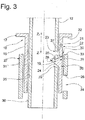
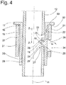
- the support rods 12 with the bearing sleeves 15 mounted thereon are moved in the direction z1 into the assembly seat 30 (please refer Fig. 3 ) until each bearing sleeve 15 is arranged in a mounting seat 30 (see Fig. 4 ).
- the bearing sleeve 15 is arranged in the assembly seat 30 when a lower surface 32 of the annular web 17 rests on an end surface 33 of the sleeve structure 31.
- the sleeve structure 31 comprises a recess 34 which is arranged approximately opposite the recess 29 of the support rod 12 when the support rod 12 is in the first relative position and the bearing sleeve 15 is in the assembly seat 30.
- the support rod 12 is arranged relative to the bearing sleeve 15 in the second relative position and the locking element 18 is arranged in the locking position.
- the locking surface 25 is positioned in relation to the mating surface 26 in such a way that a movement of the bearing sleeve 15 in direction z2 is locked.
- the interaction of the lower surface 32 of the bearing sleeve 15 with the end face 33 of the backrest structure 27 prevents the bearing sleeve 15 from moving in the direction z1.
- a region 38 of the outer surface 36 of the support rod 12 prevents the locking element 18 from moving back into the assembly position.
- the recess 23 is arranged in relation to the locking element 21 in such a way that it can move in direction x into engagement with the recess 23, so that a movement of the support rod 12 in the directions z1 and z2 relative to the bearing sleeve 15 is locked.
- the locking element 21 is in engagement with in the x direction the recess 23 loaded. The headrest 10 is thus fully assembled and held firmly on the structure 27 of the backrest 13.
Landscapes
- Engineering & Computer Science (AREA)
- Aviation & Aerospace Engineering (AREA)
- Transportation (AREA)
- Mechanical Engineering (AREA)
- Chair Legs, Seat Parts, And Backrests (AREA)
- Seats For Vehicles (AREA)
Claims (10)
- Appuie-tête (10) comprenant une partie d'appui de tête (11) sur laquelle au moins une barre de support (12) destinée à s'appuyer sur le dossier (13) d'un siège de véhicule (14) est maintenue de façon immobile ou de façon mobile par rapport à la partie d'appui de tête (11), comprenant une douille de palier (15) dans laquelle la barre de support (12) est montée, dans lequel la douille de palier (15) présente, en vue de son verrouillage sur une structure (27) du siège de véhicule (14), un élément de verrou (18) qui est déplaçable entre une position de verrouillage, dans laquelle l'élément de verrou (18) est saillant au-dessus d'une face extérieure (36) de la douille de palier (15), et une position de montage dans laquelle elle est moins saillante au-dessus d'une face extérieure (36) de la douille de palier (15) par rapport à la position de verrouillage, caractérisé en ce que la barre de support (12) comporte une découpe (29) dans laquelle l'élément de verrou peut s'engager dans la position de montage.
- Appuie-tête selon la revendication 1, caractérisé en ce que l'élément de verrou (18) présente une face de contact (24) qui coopère avec une face de la barre de support (12), dans lequel l'élément de verrou (18) est déplaçable dans la position de verrouillage par un déplacement relatif de la barre de support (12) entre la barre de support (12) et la douille de palier (15).
- Appuie-tête selon la revendication 2, caractérisé en ce que la face de contact (24) dans la position de montage est disposée en oblique par rapport à une direction de déplacement (z2) de la barre de support (12), de telle manière que, lors du contact entre la barre de support (12) et l'élément de verrou (18), une force qui agit dans la direction axiale de la barre de support (12) puisse être transmise à l'élément de verrou (18) et puisse être déviée en une force radiale, dans le but de déplacer l'élément de verrou (18) dans la position de verrouillage.
- Appuie-tête selon l'une quelconque des revendications précédentes, caractérisé en ce que l'élément de verrou (18) présente une face de verrou (25) qui, dans la position de verrouillage, peut coopérer avec une face opposée (26) de la structure de dossier (27) et empêche un déplacement de la douille de palier (15) dans la direction de démontage (z2) de la douille de palier (15).
- Appuie-tête selon l'une quelconque des revendications précédentes, caractérisé en ce que l'élément de verrouillage (18) dans la position de montage peut se trouver dans au moins une première position relative entre la douille de palier (15) et la barre de support (12), et en ce que dans au moins une seconde position relative la barre de support (12) empêche un déplacement à partir de la position de verrouillage jusque dans la position de montage.
- Appuie-tête selon l'une quelconque des revendications précédentes, caractérisé en ce que la douille de palier (15) comprend un élément d'arrêt (21), qui peut être mis en prise avec un évidement (23) de la barre de support (12), dans le but d'empêcher un déplacement relatif axial entre la douille de palier (15) et la barre de support (12) dans au moins une direction (z2).
- Procédé de montage d'un appuie-tête (10) sur la structure (27) d'un dossier (13) de siège de véhicule (14), comprenant les étapes suivantes:engager une douille de palier (15) sur au moins une barre de support (12) dans une première position relative, de telle manière qu'un élément de verrou (18) de la douille de palier (15) soit disposé dans une position de montage dans laquelle l'élément de verrou (18) pénètre dans une découpe (29) de la barre de support (12) et une face de verrou (25) de l'élément de verrou (18) est moins saillante par rapport à une position de verrou au-dessus d'une face extérieure (36) de la douille de palier (15),engager la douille de palier (15) en même temps que la partie d'appui de tête (11) et la barre de support (12) fixée à celle-ci dans un siège de montage (30) de la structure (27), etdéplacer l'élément de verrou (18) à partir de la position de montage jusque dans la position de verrouillage dans laquelle l'élément de verrou (18) est saillant au-dessus d'une face extérieure (36) de la douille de palier (15) et une face de verrou (25) de l'élément de verrou (18) coopère par verrouillage avec une face opposée (26) de la structure (27).
- Procédé selon la revendication 7, caractérisé par un déplacement relatif entre la barre de support (12) et la douille de palier (15) à partir de la première position relative jusque dans une seconde position relative.
- Procédé selon la revendication 8, caractérisé en ce que l'on déplace l'élément de verrou dans la position de verrouillage pendant le déplacement de la barre de support (12) entre la première position relative et la seconde position relative.
- Procédé selon la revendication 8 ou 9, caractérisé en ce que l'on déplace dans la seconde position relative un élément d'arrêt (21) de la douille de palier (15) en prise avec un évidement (23) de la barre de support (12), dans le but d'empêcher un déplacement axial de la barre de support (12) par rapport à la douille de palier (15).
Applications Claiming Priority (1)
| Application Number | Priority Date | Filing Date | Title |
|---|---|---|---|
| DE102017004485.6A DE102017004485B3 (de) | 2017-05-10 | 2017-05-10 | Kopfstütze und Verfahren zur Montage einer Kopfstütze |
Publications (2)
| Publication Number | Publication Date |
|---|---|
| EP3406482A1 EP3406482A1 (fr) | 2018-11-28 |
| EP3406482B1 true EP3406482B1 (fr) | 2020-08-26 |
Family
ID=61868461
Family Applications (1)
| Application Number | Title | Priority Date | Filing Date |
|---|---|---|---|
| EP18165466.6A Active EP3406482B1 (fr) | 2017-05-10 | 2018-04-03 | Appuie-tête et procédé de montage d'un appuie-tête |
Country Status (2)
| Country | Link |
|---|---|
| EP (1) | EP3406482B1 (fr) |
| DE (1) | DE102017004485B3 (fr) |
Families Citing this family (2)
| Publication number | Priority date | Publication date | Assignee | Title |
|---|---|---|---|---|
| CN111685525A (zh) * | 2020-06-24 | 2020-09-22 | 上海延锋座椅有限公司 | 一种双锁止头枕导套结构 |
| DE102021119621B4 (de) | 2021-07-28 | 2024-12-05 | Grammer Aktiengesellschaft | Halteteil zur Lagerung einer Kopfstütze sowie Kopfstützenvorrichtung mit wenigstens einem Halteteil und Verfahren zur Montage eines Halteteils |
Family Cites Families (5)
| Publication number | Priority date | Publication date | Assignee | Title |
|---|---|---|---|---|
| JP3513646B2 (ja) * | 1998-09-29 | 2004-03-31 | 株式会社パイオラックス | ヘッドレストの支持構造 |
| US6802565B2 (en) * | 2002-05-29 | 2004-10-12 | Centura Group, Inc. | Head restraint assembly for motor vehicle |
| FR2881089B1 (fr) * | 2005-01-26 | 2008-08-29 | Itw De France Sas | Gaine de reception d'une d'appui-tete |
| DE102013005246B4 (de) | 2013-03-27 | 2023-08-10 | Grammer Aktiengesellschaft | Lagervorrichtung sowie Fahrzeugsitz mit einer Lagervorrichtung |
| DE102013009469B4 (de) | 2013-06-06 | 2018-07-26 | Grammer Aktiengesellschaft | Kopfstütze |
-
2017
- 2017-05-10 DE DE102017004485.6A patent/DE102017004485B3/de active Active
-
2018
- 2018-04-03 EP EP18165466.6A patent/EP3406482B1/fr active Active
Non-Patent Citations (1)
| Title |
|---|
| None * |
Also Published As
| Publication number | Publication date |
|---|---|
| EP3406482A1 (fr) | 2018-11-28 |
| DE102017004485B3 (de) | 2018-06-14 |
Similar Documents
| Publication | Publication Date | Title |
|---|---|---|
| EP3045347B1 (fr) | Dispositif de stockage et appui-tete | |
| DE102015011477B4 (de) | Kopfstütze | |
| EP3170694B1 (fr) | Accoudoir | |
| DE102009015463A1 (de) | Neigungsverstellvorrichtung für einen Fahrzeugsitz | |
| EP3456583A1 (fr) | Accoudoir | |
| EP3406482B1 (fr) | Appuie-tête et procédé de montage d'un appuie-tête | |
| WO2020126327A1 (fr) | Ensemble système de direction conçu pour un véhicule automobile | |
| DE19806790B4 (de) | Vorrichtung an einem Betätigungsorgan, insbesondere einer Türgriffanordnung an einem Kraftfahrzeug | |
| EP3392078B1 (fr) | Dispositif d'articulation, dispositif d'aménagement d'un habitacle comprenant un dispositif d'articulation ainsi que procédé de montage du dispositif d'articulation | |
| DE112022000583T5 (de) | Halterungseinsatz für eine kopfstützenhülsenvorrichtung, eine hülsenvorrichtungsbaugruppe davon | |
| DE102010048956A1 (de) | Vorrichtung und Verfahren zur Befestigung eines mindestens eine Öffnung aufweisenden Bauteils an einem Trägerteil | |
| EP3059117B1 (fr) | Appuie-tete | |
| EP3819513B1 (fr) | Palier lisse, dispositif d'équipement pourvu d'au moins un palier lisse et dispositif d'équipement pourvu d'au moins un palier logé rotatif | |
| DE102014001821A1 (de) | Vorrichtung zur Positionierung eines Gassackmoduls in einem Kraftfahrzeug | |
| EP3727091B1 (fr) | Arrangement comprenant une tringle et un element mural d'un tiroir | |
| EP0063294B1 (fr) | Dispositif de fixation, en particulier pour accoudoir ou poignées à la paroi intérieure de carosserie pour véhicules | |
| EP3045617B1 (fr) | Rosette et système de loquet de porte ou de fenêtre et d'une rosette sur une ouverture de vantail de fenêtre ou de porte ou similaire | |
| DE102016115267B4 (de) | Vorrichtung zum Einstellen einer Rückenlehnenneigung und Verfahren zur Montage der Vorrichtung | |
| EP3802206B1 (fr) | Dispositif de palier et appuie-tête | |
| EP3531193A1 (fr) | Partie charnière à ressort pour une monture de lunette, charnière à ressort dotée d'une telle partie charnière à ressort et procédé de montage d'une telle partie charnière à ressort | |
| DE102019208534B4 (de) | Kopfstützenhalterung und Kopfstützenanordnung | |
| DE102018114585A1 (de) | Schubkasten und Verfahren zur Montage einer Rückwand an einer Seitenzarge eines Schubkastens | |
| DE60200712T2 (de) | Einstellbarer Anschlag für bewegliche Teile einer Fahrzeugkarosserie | |
| EP3967549A1 (fr) | Dispositif palier pour un appui-tête | |
| DE102013010251A1 (de) | Abstimmbarer Anschraubpunkt eines Kunststoffbauteils |
Legal Events
| Date | Code | Title | Description |
|---|---|---|---|
| PUAI | Public reference made under article 153(3) epc to a published international application that has entered the european phase |
Free format text: ORIGINAL CODE: 0009012 |
|
| STAA | Information on the status of an ep patent application or granted ep patent |
Free format text: STATUS: THE APPLICATION HAS BEEN PUBLISHED |
|
| AK | Designated contracting states |
Kind code of ref document: A1 Designated state(s): AL AT BE BG CH CY CZ DE DK EE ES FI FR GB GR HR HU IE IS IT LI LT LU LV MC MK MT NL NO PL PT RO RS SE SI SK SM TR |
|
| AX | Request for extension of the european patent |
Extension state: BA ME |
|
| STAA | Information on the status of an ep patent application or granted ep patent |
Free format text: STATUS: REQUEST FOR EXAMINATION WAS MADE |
|
| 17P | Request for examination filed |
Effective date: 20190502 |
|
| RBV | Designated contracting states (corrected) |
Designated state(s): AL AT BE BG CH CY CZ DE DK EE ES FI FR GB GR HR HU IE IS IT LI LT LU LV MC MK MT NL NO PL PT RO RS SE SI SK SM TR |
|
| RIC1 | Information provided on ipc code assigned before grant |
Ipc: B60N 2/897 20180101AFI20200408BHEP Ipc: B60N 2/809 20180101ALI20200408BHEP Ipc: B60N 2/818 20180101ALI20200408BHEP |
|
| GRAP | Despatch of communication of intention to grant a patent |
Free format text: ORIGINAL CODE: EPIDOSNIGR1 |
|
| STAA | Information on the status of an ep patent application or granted ep patent |
Free format text: STATUS: GRANT OF PATENT IS INTENDED |
|
| INTG | Intention to grant announced |
Effective date: 20200526 |
|
| GRAS | Grant fee paid |
Free format text: ORIGINAL CODE: EPIDOSNIGR3 |
|
| GRAA | (expected) grant |
Free format text: ORIGINAL CODE: 0009210 |
|
| STAA | Information on the status of an ep patent application or granted ep patent |
Free format text: STATUS: THE PATENT HAS BEEN GRANTED |
|
| RBV | Designated contracting states (corrected) |
Designated state(s): AL AT BE BG CH CY CZ DK EE ES FI FR GB GR HR HU IE IS IT LI LT LU LV MC MK MT NL NO PL PT RO RS SE SI SK SM TR |
|
| REG | Reference to a national code |
Ref country code: DE Ref legal event code: R108 |
|
| AK | Designated contracting states |
Kind code of ref document: B1 Designated state(s): AL AT BE BG CH CY CZ DK EE ES FI FR GB GR HR HU IE IS IT LI LT LU LV MC MK MT NL NO PL PT RO RS SE SI SK SM TR |
|
| REG | Reference to a national code |
Ref country code: GB Ref legal event code: FG4D Free format text: NOT ENGLISH |
|
| REG | Reference to a national code |
Ref country code: CH Ref legal event code: EP |
|
| REG | Reference to a national code |
Ref country code: AT Ref legal event code: REF Ref document number: 1306065 Country of ref document: AT Kind code of ref document: T Effective date: 20200915 |
|
| REG | Reference to a national code |
Ref country code: IE Ref legal event code: FG4D Free format text: LANGUAGE OF EP DOCUMENT: GERMAN |
|
| RAP2 | Party data changed (patent owner data changed or rights of a patent transferred) |
Owner name: GRAMMER AG |
|
| REG | Reference to a national code |
Ref country code: LT Ref legal event code: MG4D |
|
| PG25 | Lapsed in a contracting state [announced via postgrant information from national office to epo] |
Ref country code: GR Free format text: LAPSE BECAUSE OF FAILURE TO SUBMIT A TRANSLATION OF THE DESCRIPTION OR TO PAY THE FEE WITHIN THE PRESCRIBED TIME-LIMIT Effective date: 20201127 Ref country code: SE Free format text: LAPSE BECAUSE OF FAILURE TO SUBMIT A TRANSLATION OF THE DESCRIPTION OR TO PAY THE FEE WITHIN THE PRESCRIBED TIME-LIMIT Effective date: 20200826 Ref country code: BG Free format text: LAPSE BECAUSE OF FAILURE TO SUBMIT A TRANSLATION OF THE DESCRIPTION OR TO PAY THE FEE WITHIN THE PRESCRIBED TIME-LIMIT Effective date: 20201126 Ref country code: NO Free format text: LAPSE BECAUSE OF FAILURE TO SUBMIT A TRANSLATION OF THE DESCRIPTION OR TO PAY THE FEE WITHIN THE PRESCRIBED TIME-LIMIT Effective date: 20201126 Ref country code: FI Free format text: LAPSE BECAUSE OF FAILURE TO SUBMIT A TRANSLATION OF THE DESCRIPTION OR TO PAY THE FEE WITHIN THE PRESCRIBED TIME-LIMIT Effective date: 20200826 Ref country code: HR Free format text: LAPSE BECAUSE OF FAILURE TO SUBMIT A TRANSLATION OF THE DESCRIPTION OR TO PAY THE FEE WITHIN THE PRESCRIBED TIME-LIMIT Effective date: 20200826 Ref country code: LT Free format text: LAPSE BECAUSE OF FAILURE TO SUBMIT A TRANSLATION OF THE DESCRIPTION OR TO PAY THE FEE WITHIN THE PRESCRIBED TIME-LIMIT Effective date: 20200826 Ref country code: PT Free format text: LAPSE BECAUSE OF FAILURE TO SUBMIT A TRANSLATION OF THE DESCRIPTION OR TO PAY THE FEE WITHIN THE PRESCRIBED TIME-LIMIT Effective date: 20201228 |
|
| REG | Reference to a national code |
Ref country code: NL Ref legal event code: MP Effective date: 20200826 |
|
| PG25 | Lapsed in a contracting state [announced via postgrant information from national office to epo] |
Ref country code: LV Free format text: LAPSE BECAUSE OF FAILURE TO SUBMIT A TRANSLATION OF THE DESCRIPTION OR TO PAY THE FEE WITHIN THE PRESCRIBED TIME-LIMIT Effective date: 20200826 Ref country code: PL Free format text: LAPSE BECAUSE OF FAILURE TO SUBMIT A TRANSLATION OF THE DESCRIPTION OR TO PAY THE FEE WITHIN THE PRESCRIBED TIME-LIMIT Effective date: 20200826 Ref country code: RS Free format text: LAPSE BECAUSE OF FAILURE TO SUBMIT A TRANSLATION OF THE DESCRIPTION OR TO PAY THE FEE WITHIN THE PRESCRIBED TIME-LIMIT Effective date: 20200826 Ref country code: NL Free format text: LAPSE BECAUSE OF FAILURE TO SUBMIT A TRANSLATION OF THE DESCRIPTION OR TO PAY THE FEE WITHIN THE PRESCRIBED TIME-LIMIT Effective date: 20200826 Ref country code: IS Free format text: LAPSE BECAUSE OF FAILURE TO SUBMIT A TRANSLATION OF THE DESCRIPTION OR TO PAY THE FEE WITHIN THE PRESCRIBED TIME-LIMIT Effective date: 20201226 |
|
| PG25 | Lapsed in a contracting state [announced via postgrant information from national office to epo] |
Ref country code: SM Free format text: LAPSE BECAUSE OF FAILURE TO SUBMIT A TRANSLATION OF THE DESCRIPTION OR TO PAY THE FEE WITHIN THE PRESCRIBED TIME-LIMIT Effective date: 20200826 Ref country code: EE Free format text: LAPSE BECAUSE OF FAILURE TO SUBMIT A TRANSLATION OF THE DESCRIPTION OR TO PAY THE FEE WITHIN THE PRESCRIBED TIME-LIMIT Effective date: 20200826 Ref country code: RO Free format text: LAPSE BECAUSE OF FAILURE TO SUBMIT A TRANSLATION OF THE DESCRIPTION OR TO PAY THE FEE WITHIN THE PRESCRIBED TIME-LIMIT Effective date: 20200826 Ref country code: CZ Free format text: LAPSE BECAUSE OF FAILURE TO SUBMIT A TRANSLATION OF THE DESCRIPTION OR TO PAY THE FEE WITHIN THE PRESCRIBED TIME-LIMIT Effective date: 20200826 Ref country code: DK Free format text: LAPSE BECAUSE OF FAILURE TO SUBMIT A TRANSLATION OF THE DESCRIPTION OR TO PAY THE FEE WITHIN THE PRESCRIBED TIME-LIMIT Effective date: 20200826 |
|
| PG25 | Lapsed in a contracting state [announced via postgrant information from national office to epo] |
Ref country code: ES Free format text: LAPSE BECAUSE OF FAILURE TO SUBMIT A TRANSLATION OF THE DESCRIPTION OR TO PAY THE FEE WITHIN THE PRESCRIBED TIME-LIMIT Effective date: 20200826 Ref country code: AL Free format text: LAPSE BECAUSE OF FAILURE TO SUBMIT A TRANSLATION OF THE DESCRIPTION OR TO PAY THE FEE WITHIN THE PRESCRIBED TIME-LIMIT Effective date: 20200826 |
|
| PG25 | Lapsed in a contracting state [announced via postgrant information from national office to epo] |
Ref country code: SK Free format text: LAPSE BECAUSE OF FAILURE TO SUBMIT A TRANSLATION OF THE DESCRIPTION OR TO PAY THE FEE WITHIN THE PRESCRIBED TIME-LIMIT Effective date: 20200826 |
|
| PLBE | No opposition filed within time limit |
Free format text: ORIGINAL CODE: 0009261 |
|
| STAA | Information on the status of an ep patent application or granted ep patent |
Free format text: STATUS: NO OPPOSITION FILED WITHIN TIME LIMIT |
|
| 26N | No opposition filed |
Effective date: 20210527 |
|
| PG25 | Lapsed in a contracting state [announced via postgrant information from national office to epo] |
Ref country code: SI Free format text: LAPSE BECAUSE OF FAILURE TO SUBMIT A TRANSLATION OF THE DESCRIPTION OR TO PAY THE FEE WITHIN THE PRESCRIBED TIME-LIMIT Effective date: 20200826 |
|
| PG25 | Lapsed in a contracting state [announced via postgrant information from national office to epo] |
Ref country code: MC Free format text: LAPSE BECAUSE OF FAILURE TO SUBMIT A TRANSLATION OF THE DESCRIPTION OR TO PAY THE FEE WITHIN THE PRESCRIBED TIME-LIMIT Effective date: 20200826 |
|
| PG25 | Lapsed in a contracting state [announced via postgrant information from national office to epo] |
Ref country code: LU Free format text: LAPSE BECAUSE OF NON-PAYMENT OF DUE FEES Effective date: 20210403 |
|
| REG | Reference to a national code |
Ref country code: BE Ref legal event code: MM Effective date: 20210430 |
|
| PG25 | Lapsed in a contracting state [announced via postgrant information from national office to epo] |
Ref country code: CH Free format text: LAPSE BECAUSE OF NON-PAYMENT OF DUE FEES Effective date: 20210430 Ref country code: LI Free format text: LAPSE BECAUSE OF NON-PAYMENT OF DUE FEES Effective date: 20210430 |
|
| PG25 | Lapsed in a contracting state [announced via postgrant information from national office to epo] |
Ref country code: IE Free format text: LAPSE BECAUSE OF NON-PAYMENT OF DUE FEES Effective date: 20210403 |
|
| PG25 | Lapsed in a contracting state [announced via postgrant information from national office to epo] |
Ref country code: IS Free format text: LAPSE BECAUSE OF FAILURE TO SUBMIT A TRANSLATION OF THE DESCRIPTION OR TO PAY THE FEE WITHIN THE PRESCRIBED TIME-LIMIT Effective date: 20201226 |
|
| PG25 | Lapsed in a contracting state [announced via postgrant information from national office to epo] |
Ref country code: BE Free format text: LAPSE BECAUSE OF NON-PAYMENT OF DUE FEES Effective date: 20210430 |
|
| PG25 | Lapsed in a contracting state [announced via postgrant information from national office to epo] |
Ref country code: CY Free format text: LAPSE BECAUSE OF FAILURE TO SUBMIT A TRANSLATION OF THE DESCRIPTION OR TO PAY THE FEE WITHIN THE PRESCRIBED TIME-LIMIT Effective date: 20200826 |
|
| PG25 | Lapsed in a contracting state [announced via postgrant information from national office to epo] |
Ref country code: HU Free format text: LAPSE BECAUSE OF FAILURE TO SUBMIT A TRANSLATION OF THE DESCRIPTION OR TO PAY THE FEE WITHIN THE PRESCRIBED TIME-LIMIT; INVALID AB INITIO Effective date: 20180403 |
|
| PG25 | Lapsed in a contracting state [announced via postgrant information from national office to epo] |
Ref country code: MK Free format text: LAPSE BECAUSE OF FAILURE TO SUBMIT A TRANSLATION OF THE DESCRIPTION OR TO PAY THE FEE WITHIN THE PRESCRIBED TIME-LIMIT Effective date: 20200826 |
|
| REG | Reference to a national code |
Ref country code: AT Ref legal event code: MM01 Ref document number: 1306065 Country of ref document: AT Kind code of ref document: T Effective date: 20230403 |
|
| PG25 | Lapsed in a contracting state [announced via postgrant information from national office to epo] |
Ref country code: TR Free format text: LAPSE BECAUSE OF FAILURE TO SUBMIT A TRANSLATION OF THE DESCRIPTION OR TO PAY THE FEE WITHIN THE PRESCRIBED TIME-LIMIT Effective date: 20200826 |
|
| PG25 | Lapsed in a contracting state [announced via postgrant information from national office to epo] |
Ref country code: AT Free format text: LAPSE BECAUSE OF NON-PAYMENT OF DUE FEES Effective date: 20230403 |
|
| PG25 | Lapsed in a contracting state [announced via postgrant information from national office to epo] |
Ref country code: AT Free format text: LAPSE BECAUSE OF NON-PAYMENT OF DUE FEES Effective date: 20230403 |
|
| PG25 | Lapsed in a contracting state [announced via postgrant information from national office to epo] |
Ref country code: MT Free format text: LAPSE BECAUSE OF FAILURE TO SUBMIT A TRANSLATION OF THE DESCRIPTION OR TO PAY THE FEE WITHIN THE PRESCRIBED TIME-LIMIT Effective date: 20200826 |
|
| PGFP | Annual fee paid to national office [announced via postgrant information from national office to epo] |
Ref country code: IT Payment date: 20250430 Year of fee payment: 8 |
|
| PGFP | Annual fee paid to national office [announced via postgrant information from national office to epo] |
Ref country code: FR Payment date: 20250425 Year of fee payment: 8 |
|
| PGFP | Annual fee paid to national office [announced via postgrant information from national office to epo] |
Ref country code: GB Payment date: 20260324 Year of fee payment: 9 |
|
| PGFP | Annual fee paid to national office [announced via postgrant information from national office to epo] |
Ref country code: AT Payment date: 20260410 Year of fee payment: 5 |