EP3406482A1 - Appuie-tête et procédé de montage d'un appuie-tête - Google Patents
Appuie-tête et procédé de montage d'un appuie-tête Download PDFInfo
- Publication number
- EP3406482A1 EP3406482A1 EP18165466.6A EP18165466A EP3406482A1 EP 3406482 A1 EP3406482 A1 EP 3406482A1 EP 18165466 A EP18165466 A EP 18165466A EP 3406482 A1 EP3406482 A1 EP 3406482A1
- Authority
- EP
- European Patent Office
- Prior art keywords
- bearing sleeve
- support rod
- locking element
- locking
- headrest
- Prior art date
- Legal status (The legal status is an assumption and is not a legal conclusion. Google has not performed a legal analysis and makes no representation as to the accuracy of the status listed.)
- Granted
Links
Images


Classifications
-
- B—PERFORMING OPERATIONS; TRANSPORTING
- B60—VEHICLES IN GENERAL
- B60N—SEATS SPECIALLY ADAPTED FOR VEHICLES; VEHICLE PASSENGER ACCOMMODATION NOT OTHERWISE PROVIDED FOR
- B60N2/00—Seats specially adapted for vehicles; Arrangement or mounting of seats in vehicles
- B60N2/80—Head-rests
- B60N2/897—Head-rests with sleeves located in the back-rest for guiding the rods of the head-rest
-
- B—PERFORMING OPERATIONS; TRANSPORTING
- B60—VEHICLES IN GENERAL
- B60N—SEATS SPECIALLY ADAPTED FOR VEHICLES; VEHICLE PASSENGER ACCOMMODATION NOT OTHERWISE PROVIDED FOR
- B60N2/00—Seats specially adapted for vehicles; Arrangement or mounting of seats in vehicles
- B60N2/80—Head-rests
- B60N2/806—Head-rests movable or adjustable
- B60N2/809—Head-rests movable or adjustable vertically slidable
Definitions
- the invention relates according to a first aspect of a headrest.
- a headrest is known from public prior use. It comprises a headrest part, on which support rods are held, with which the headrest part can be mounted on the structure of the backrest.
- the headrest includes backrest-resistant guide sleeves made of plastic, in which the support rods inserted and are releasably locked with these. Height adjustment finds e.g. by a relative movement between the headrest part and the support rods or between the support rods and the guide sleeves instead.
- the known from the prior art support bar was mounted by the guide sleeve was moved into a seat on the backrest and locked there.
- the lock was made e.g. by locking elements of the guide sleeve, which moved into engagement with the backrest structure when the guide sleeve was arranged in its seat. Thereafter, the support rods were mounted in the guide sleeves.
- the support bars prevented that the locking elements of the guide sleeves could move into the interior of the guide sleeve out of engagement with the structure of the backrest.
- the headrests are not always produced by the car manufacturers themselves, but by suppliers and then delivered to the car manufacturer for assembly.
- the object of the invention is to provide a device with which the mounting of the headrest on the backrest of a vehicle seat is easier to carry out.
- the headrest device comprises a head attachment part on which at least one support rod is held immovable or relatively movable relative to the head attachment part. With the support rod, the headrest part can be stored on the backrest of a vehicle seat. Furthermore, the headrest device comprises a bearing sleeve in which the support rod is mounted. The bearing sleeve is fastened to the structure of the backrest (hereinafter referred to as backrest structure).
- the bearing sleeve has a latch member movable between a latch position in which the latch member protrudes beyond an outer surface of the bearing sleeve and engages the backrest structure, and a mounting position in which the latch member moves less over an outer surface with respect to the latch position the guide sleeve protrudes.
- the mounting position protrudes e.g. the locking element
- the outer surface of the bearing sleeve is not or only slightly.
- the bearing sleeve can then be moved into a bearing seat of the backrest structure. In the locking position, the bearing sleeve is firmly connected to the backrest structure.
- the headrest can be designed without height adjustment. In this case, neither the support rod relative to the backrest, nor the headrest part can be moved relative to the support rod.
- the headrest is provided with a height adjustment, wherein the headrest part is movable relative to the support rod.
- the headrest is provided with a height adjustment, wherein the support rod is movable relative to the bearing sleeve.
- the headrest according to the invention is designed such that the guide sleeve can be pushed onto the support rod during assembly and the headrest, i. Headrest part with support rods and guide sleeves together, can be mounted on the structure of the backrest.
- the support bars have e.g. a recess into which the locking element of the guide sleeve can retreat in the mounting position when the guide sleeve is moved into the seat of the backrest structure.
- recess and recess designate in the context of the invention both a material removal, as well as a depression produced by material deformation. The terms may also refer to both apertures and closed wells.
- the locking element is e.g. moved by a relative movement between the support rod and the bearing sleeve of the support rod from the mounting position to the locking position. This means that the locking element can be moved into the locking position by a force acting on the support rod or on the bearing sleeve.
- the locking element is adjusted, for example, by a separate adjusting element between the mounting position and the locking position.
- the locking element comprises e.g. a locking surface, which cooperates in the locking position with a mating surface of the backrest structure and prevents movement of the bearing sleeve in the removal direction of the bearing sleeve. If the locking element - e.g. due to a relative movement between the support rod and the bearing sleeve - is moved into the locking position, the locking surface is arranged relative to the counter surface such that the interaction of locking surface and counter surface prevents relative movement between the bearing sleeve and backrest structure in at least one direction.
- the locking element is e.g. formed integrally with the bearing sleeve. It can e.g. be formed on the bearing sleeve so that it is movable. For example, can be formed between the locking element and the bearing sleeve, a film hinge. Film hinge means, for example, that the material at this point has a smaller thickness, which allows mobility only at this point.
- the locking element is e.g. reset load in the mounting position or in the locking position.
- the provision can be made by a separate spring or by the elastic restoring force of the material.
- the latch member When the latch member is loaded in the latch position, it moves e.g. not automatically back to the mounting position. That after mounting the bearing sleeve, the locking element is in the locking position and can not affect the mobility of the support rod in the bearing sleeve.
- Co-operating positive engagement means which are formed on the support rod and on the locking element, for example, releasably prevent unwanted movement of the bolt from the mounting position to the locking position.
- the bearing sleeve comprises e.g. a locking element which can be brought into engagement with a counter-element of the support rod in order to prevent an axial relative movement between the bearing sleeve and the support rod in at least one direction.
- the locking element acts e.g. in a conventional manner with a notch together. In a locking position, the locking element is engaged with the notch and prevents e.g. a movement of the support rod relative to the bearing sleeve in at least one direction of movement, e.g. in two opposite directions of movement.
- the locking element is e.g. movable in a release position, in which the support rod is displaceable relative to the bearing sleeve.
- the assembly comprising the headrest part, the support rods and the bearing sleeves mounted on the support rods can be mounted in the mounting seats of the backrest structure.
- the first relative position to the second relative position e.g. prevents the latch member from moving back to the mounting position.
- moving from the first relative position to the second relative position e.g. moves the locking element from the mounting position to the locking position.
- the second relative position prevents e.g. a wall of the support rod, the return movement of the locking element in the mounting position.
- the locking element is arranged to the counter-element such that it can be moved into the locking position.
- the invention also relates to a method for mounting a headrest.
- the object was achieved by a method for mounting a headrest with the features of claim 8.
- a headrest part is used, to which at least one support rod is attached to be movable on a backrest structure of a vehicle seat movable or immovable.
- a bearing sleeve is attached, e.g. in such a way that a locking element arranged in the mounting position projects into a recess of the support rod and in this way does not protrude beyond an outer surface of the support rod.
- the pre-assembled assembly can then be supplied for mounting on the vehicle seat.
- the bearing sleeve is arranged together with the head attachment part and the support rod attached thereto in a mounting seat of the backrest structure.
- the locking element is moved from the mounting position into the locking position, in which a relative movement between the bearing sleeve and the seat structure is locked at least in the dismounting direction.
- the support rod is moved after the arrangement of the bearing sleeve in the mounting seat from a first relative position to a second relative position.
- the locking element can be moved from the mounting position to the locking position.
- a restoring force movement in the Effect locking position can also be, for example, the elastic restoring force of the material, in particular since, for example, the movement from the assembly position into the locking position usually takes place only once, at most a few times.
- the relative movement can cause the locking element is secured in the locking position.
- the fuse may e.g. be effected in that the support rod outer surface prevents movement of the locking element from the locking position to the mounting position.
- the relative movement can cause that in the second relative position, the locking element of the bearing sleeve is movable from a release position to a locking position, wherein in the release position movement of the support rod relative to the bearing sleeve is possible and in the locking position, the locking element in a counter element of Support rod engages and thus a relative movement of the support rod with respect to the bearing sleeve in at least one direction, in particular in two directions, locked.
- a headrest device is denoted overall by the reference numeral 10.
- Like reference numerals in the various figures indicate corresponding parts, even if small letters are readjusted or omitted.
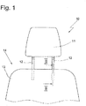
- the headrest 10 includes according to Fig. 1 a headrest part 11 which is mounted by means of support rods 12 to the structure of a backrest 13 of a vehicle seat 14, which is only partially shown.
- the support rods 12 are formed in the present embodiment as a pipe with a central axis m, but they can also be made of solid material according to an alternative embodiment. Instead of single support rods may alternatively also a support bar bracket be used. In this case, the support rods 12 are to be understood as free ends of the support bar bracket.
- bearing sleeves 15 are used, which are usually made of plastic.
- the bearing sleeves 15 are in Fig. 1 not shown.
- the bearing sleeves 15 prevent noise between the usually metallic backrest structure and the support rod 12 made of metal.
- the bearing sleeve 15 fit inaccuracies can be compensated.
- the bearing sleeve 15 has an inner surface 35, which - contrary to the representation in the Fig. 2 to 5 - Is in contact with an outer surface 36 of the support rod 12.
- the support rod 12 is directly in contact with the inner surface 35 of the bearing sleeve 15.
- the inner surface 35 may also form projections and / or ribs and / or elastic arms, which are in contact with the support rod 12.
- the invention is independent of the manner of storage and management of the support rod 12 on the bearing sleeve 15. Also on the shape of the support rod 12 is not important in the invention.
- the bearing sleeve 15 may be circular or even angular in cross section, for example.
- the bearing sleeve 15 is provided with a ring land 17 which projects radially outwardly beyond the bearing sleeve 15.
- a locking element 18 is divided so that a free end portion 19 is formed.
- the junction between the end portion 19 and the bearing sleeve 15 is formed for example as a film hinge joint 20, that is, the material of the wall of the bearing sleeve 15 is at this point of a thickness that movement of the locking element 18 between a in Fig. 2 shown assembly position and a in Fig. 5 shown locking position is possible.
- the locking element 18 is pivotable in the directions u1 and u2 between the mounting position and the locking position.
- the locking element 18 comprises a contact surface 24 which forms an acute angle in the mounting position with a movement direction z2 of the support rod 12. In this way, a region of the support rod 12 in a movement of the support rod 12 relative to the bearing sleeve 15 in the direction z2 exert a force on the locking element 18, which moves the locking element in the locking position.
- the first locking element further comprises a locking surface 25, which in the locking position according to Fig. 5 cooperates with a mating surface 26 of a backrest structure 27 to prevent movement of the bearing sleeve 15 in the direction x2 from the mounting seat by a lock.
- a projection 28 of the locking element 18 cooperates with the support rod 12 in a form-fitting manner in the mounting position and prevents unintentional movement out of the mounting position, e.g. in the latch position.
- the projection 28 is elastically deformable on exceeding a threshold force on the contact surface 24, so that the locking element 18 can be moved from the mounting position to the locking position.
- the locking element 18 also prevents the bearing sleeve 15 from moving out of a defined relative position to the support rod 12.
- the bearing sleeve 15 comprises a locking element 21.
- the locking element 21 is attached to the bearing sleeve 15.
- the locking element 21 is movable between a release position and a locking position and loaded by its elastic restoring force in the locking position.
- a separate spring could load the locking element 21 in the locking position.
- the locking element 21 may be arranged for example in a recess 22 of the bearing sleeve 15. Contrary to the illustration in Fig. 2 can the recess 22 instead of a breakthrough in the wall of the bearing sleeve 15 and a mere recess, so be a depression in the wall of the bearing sleeve 15.
- the locking element 21 is in engagement with a recess 23 of the support rod 12.
- the recess 23 may also be opposite to the representation in Fig. 2 instead of a breakthrough be a mere depression in the surface of the support rod 12, which is prepared for example by an impression in the wall of the support rod 12.
- the support rod 12 in the present embodiment according to Fig. 5 immovable in both directions z1 and z2 relative to the bearing sleeve 15.
- the support bar 12 can be moved relative to the bearing sleeve 15 in the directions z1 and z2 when the locking element 18 is in the locking position.
- the recess 23 may also be formed with an edge formed transversely to the direction of movement z2 edge and an obliquely to the direction of movement z1 shaped ramp that the support rod 12 in the Arretierposition immovable only in the direction z2 relative to the bearing sleeve 15, in the direction z1, however, is movable.
- the embodiment corresponds to Fig. 6 the first embodiment according to the Fig. 1 to 5
- a recess 29 is provided in the support rod 12 is - for engagement of the first locking element in the mounting position - a recess 29 is provided.
- the recess 29 may be contrary to the representation in Fig. 2 instead of one Breakthrough be a mere depression in the surface of the support rod 12, which was prepared for example by an impression in the wall of the support rod 12. Due to the recess 29, the locking element 18 can move into the mounting position.
- a positive connection between the support rod 12 and the bearing sleeve 15, which prevents the bearing sleeve 12 - eg during transport of the headrest 10 - from its relative position to the Support rod 12 moves.
- the assembly process can be carried out as follows.
- the finished manufactured headrest part 11 with the support rods 12 attached thereto is provided and on each support rod 12, a bearing sleeve 15 is attached and brought into the first relative position to the support rod 12.
- each free end is a support rod 12 in the sense of this application.
- the locking element 18 is moved into the mounting position, ie in engagement with the recess 29, wherein the projection 28 is positively engaged with a structure of the support rod 12 (see Fig. 2 ).
- the projection 28 with a soffit 37 of the recess 29 is engaged.
- the headrest 10 preassembled in this way can then be packaged and delivered to the assembly line of the automobile manufacturer.
- the structure 27 of the backrest 13 of the vehicle seat 14 is provided with mounting seats 30.
- Each mounting seat 30 is formed in the present embodiment of a sleeve 31, for example, a circular cylindrical in cross-section sleeve which is attached to the structure 27, for example by a welding operation.
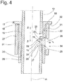
- the support rods 12 with the bearing sleeves 15 mounted thereon are moved in the direction of z1 in the mounting seat 30 (please refer Fig. 3 ), until each bearing sleeve 15 is arranged in a mounting seat 30 (see Fig. 4 ).
- the bearing sleeve 15 is arranged in the mounting seat 30 when a lower surface 32 of the annular web 17 rests on an end face 33 of the sleeve structure 31.
- the sleeve structure 31 comprises a recess 34, which is arranged approximately opposite the recess 29 of the support rod 12, when the support rod 12 is in the first relative position and the bearing sleeve 15 in the mounting seat 30.
- the support rod 12 is arranged relative to the bearing sleeve 15 in the second relative position and the locking element 18 is arranged in the locking position.
- the locking surface 25 is positioned relative to the mating surface 26 such that movement of the bearing sleeve 15 in the direction z2 is locked.
- the interaction of the lower surface 32 of the bearing sleeve 15 with the end face 33 of the backrest structure 27 prevents movement of the bearing sleeve 15 in the direction z1.
- a region 38 of the outer surface 36 of the support rod 12 prevents a return movement of the locking element 18 in the mounting position.
- the recess 23 is arranged to the locking member 21 so that it can move in the direction x in engagement with the recess 23, so that a movement of the support rod 12 in the directions z1 and z2 is locked relative to the bearing sleeve 15.
- the locking element 21 is in the direction x in engagement with the recess 23 loaded.
Landscapes
- Engineering & Computer Science (AREA)
- Aviation & Aerospace Engineering (AREA)
- Transportation (AREA)
- Mechanical Engineering (AREA)
- Chair Legs, Seat Parts, And Backrests (AREA)
- Seats For Vehicles (AREA)
Applications Claiming Priority (1)
| Application Number | Priority Date | Filing Date | Title |
|---|---|---|---|
| DE102017004485.6A DE102017004485B3 (de) | 2017-05-10 | 2017-05-10 | Kopfstütze und Verfahren zur Montage einer Kopfstütze |
Publications (2)
| Publication Number | Publication Date |
|---|---|
| EP3406482A1 true EP3406482A1 (fr) | 2018-11-28 |
| EP3406482B1 EP3406482B1 (fr) | 2020-08-26 |
Family
ID=61868461
Family Applications (1)
| Application Number | Title | Priority Date | Filing Date |
|---|---|---|---|
| EP18165466.6A Active EP3406482B1 (fr) | 2017-05-10 | 2018-04-03 | Appuie-tête et procédé de montage d'un appuie-tête |
Country Status (2)
| Country | Link |
|---|---|
| EP (1) | EP3406482B1 (fr) |
| DE (1) | DE102017004485B3 (fr) |
Cited By (2)
| Publication number | Priority date | Publication date | Assignee | Title |
|---|---|---|---|---|
| CN112450634A (zh) * | 2020-06-24 | 2021-03-09 | 延锋安道拓座椅有限公司 | 一种双锁止头枕导套结构 |
| CN115675230A (zh) * | 2021-07-28 | 2023-02-03 | 格瑞玛股份公司 | 保持件、头枕装置和用于安装保持件的方法 |
Citations (3)
| Publication number | Priority date | Publication date | Assignee | Title |
|---|---|---|---|---|
| US20030222491A1 (en) * | 2002-05-29 | 2003-12-04 | Centura Group, Inc. | Head restraint assembly for motor vehicle |
| DE69928345T2 (de) * | 1998-09-29 | 2006-08-10 | Piolax Inc., Yokohama | Tragstruktur für Kopfstütze |
| DE602006000827T2 (de) * | 2005-01-26 | 2009-04-16 | I.T.W. De France | Hülle zur Aufnahme einer Kopfstützenführungsstange |
Family Cites Families (2)
| Publication number | Priority date | Publication date | Assignee | Title |
|---|---|---|---|---|
| DE102013005246B4 (de) | 2013-03-27 | 2023-08-10 | Grammer Aktiengesellschaft | Lagervorrichtung sowie Fahrzeugsitz mit einer Lagervorrichtung |
| DE102013009469B4 (de) | 2013-06-06 | 2018-07-26 | Grammer Aktiengesellschaft | Kopfstütze |
-
2017
- 2017-05-10 DE DE102017004485.6A patent/DE102017004485B3/de active Active
-
2018
- 2018-04-03 EP EP18165466.6A patent/EP3406482B1/fr active Active
Patent Citations (3)
| Publication number | Priority date | Publication date | Assignee | Title |
|---|---|---|---|---|
| DE69928345T2 (de) * | 1998-09-29 | 2006-08-10 | Piolax Inc., Yokohama | Tragstruktur für Kopfstütze |
| US20030222491A1 (en) * | 2002-05-29 | 2003-12-04 | Centura Group, Inc. | Head restraint assembly for motor vehicle |
| DE602006000827T2 (de) * | 2005-01-26 | 2009-04-16 | I.T.W. De France | Hülle zur Aufnahme einer Kopfstützenführungsstange |
Cited By (3)
| Publication number | Priority date | Publication date | Assignee | Title |
|---|---|---|---|---|
| CN112450634A (zh) * | 2020-06-24 | 2021-03-09 | 延锋安道拓座椅有限公司 | 一种双锁止头枕导套结构 |
| CN112450634B (zh) * | 2020-06-24 | 2023-12-01 | 延锋国际座椅系统有限公司 | 一种双锁止头枕导套结构 |
| CN115675230A (zh) * | 2021-07-28 | 2023-02-03 | 格瑞玛股份公司 | 保持件、头枕装置和用于安装保持件的方法 |
Also Published As
| Publication number | Publication date |
|---|---|
| DE102017004485B3 (de) | 2018-06-14 |
| EP3406482B1 (fr) | 2020-08-26 |
Similar Documents
| Publication | Publication Date | Title |
|---|---|---|
| EP3045347B1 (fr) | Dispositif de stockage et appui-tete | |
| DE102015011477B4 (de) | Kopfstütze | |
| EP2910319B1 (fr) | Dispositif de support | |
| DE102011112418A1 (de) | Vorrichtung zur Befestigung einer Kopfstütze an einem Fahrzeugsitz und Fahrzeugsitz mit Kopfstütze | |
| DE102014103801B3 (de) | Rückenlehne für ein Kraftfahrzeug mit wenigstens zwei unabhängig voneinander verschwenkbaren Lehnenteilen | |
| DE102018121594B4 (de) | Halterung zur Verbindung eines Kindersitzes mit einem klappbaren Fahrzeugsitz | |
| EP3406482B1 (fr) | Appuie-tête et procédé de montage d'un appuie-tête | |
| DE112022000583T5 (de) | Halterungseinsatz für eine kopfstützenhülsenvorrichtung, eine hülsenvorrichtungsbaugruppe davon | |
| EP3144185A1 (fr) | Dispositif de protection a monter dans un vehicule et son procede de fabrication | |
| DE102010048956A1 (de) | Vorrichtung und Verfahren zur Befestigung eines mindestens eine Öffnung aufweisenden Bauteils an einem Trägerteil | |
| DE102021119621A1 (de) | Halteteil zur Lagerung einer Kopfstütze sowie Kopfstützenvorrichtung mit wenigstens einem Halteteil und Verfahren zur Montage eines Halteteils | |
| EP3392078B1 (fr) | Dispositif d'articulation, dispositif d'aménagement d'un habitacle comprenant un dispositif d'articulation ainsi que procédé de montage du dispositif d'articulation | |
| EP2839987B1 (fr) | Étrier de barre porte-cintres, appuie-tête et procédé de montage | |
| EP3059117B1 (fr) | Appuie-tete | |
| DE10145240A1 (de) | Kopfstütze für Fahrzeugsitze | |
| DE3731409A1 (de) | Elektromotor, insbesondere elektrischer kleinmotor | |
| DE2101047C3 (de) | Scheibenwischer | |
| DE69404908T2 (de) | Scheibenwischer mit gelenkig verbundenen Elementen | |
| DE102005005826B4 (de) | Kopfstütze | |
| EP3045617B1 (fr) | Rosette et système de loquet de porte ou de fenêtre et d'une rosette sur une ouverture de vantail de fenêtre ou de porte ou similaire | |
| DE102011050540B4 (de) | Kopfstütze für Kraftfahrzeugsitz | |
| DE102019208534B4 (de) | Kopfstützenhalterung und Kopfstützenanordnung | |
| DE102018209413B4 (de) | Tragvorrichtung für eine Schutzvorrichtung eines Kraftfahrzeugs | |
| DE102006059096A1 (de) | Baugruppe zur fahrzeugseitigen Befestigung eines Gurtschlosses | |
| DE202015005155U1 (de) | Lagerträgeranordnung und Längswellenanordnung mit einer solchen Lagerträgeranordnung |
Legal Events
| Date | Code | Title | Description |
|---|---|---|---|
| PUAI | Public reference made under article 153(3) epc to a published international application that has entered the european phase |
Free format text: ORIGINAL CODE: 0009012 |
|
| STAA | Information on the status of an ep patent application or granted ep patent |
Free format text: STATUS: THE APPLICATION HAS BEEN PUBLISHED |
|
| AK | Designated contracting states |
Kind code of ref document: A1 Designated state(s): AL AT BE BG CH CY CZ DE DK EE ES FI FR GB GR HR HU IE IS IT LI LT LU LV MC MK MT NL NO PL PT RO RS SE SI SK SM TR |
|
| AX | Request for extension of the european patent |
Extension state: BA ME |
|
| STAA | Information on the status of an ep patent application or granted ep patent |
Free format text: STATUS: REQUEST FOR EXAMINATION WAS MADE |
|
| 17P | Request for examination filed |
Effective date: 20190502 |
|
| RBV | Designated contracting states (corrected) |
Designated state(s): AL AT BE BG CH CY CZ DE DK EE ES FI FR GB GR HR HU IE IS IT LI LT LU LV MC MK MT NL NO PL PT RO RS SE SI SK SM TR |
|
| RIC1 | Information provided on ipc code assigned before grant |
Ipc: B60N 2/897 20180101AFI20200408BHEP Ipc: B60N 2/809 20180101ALI20200408BHEP Ipc: B60N 2/818 20180101ALI20200408BHEP |
|
| GRAP | Despatch of communication of intention to grant a patent |
Free format text: ORIGINAL CODE: EPIDOSNIGR1 |
|
| STAA | Information on the status of an ep patent application or granted ep patent |
Free format text: STATUS: GRANT OF PATENT IS INTENDED |
|
| INTG | Intention to grant announced |
Effective date: 20200526 |
|
| GRAS | Grant fee paid |
Free format text: ORIGINAL CODE: EPIDOSNIGR3 |
|
| GRAA | (expected) grant |
Free format text: ORIGINAL CODE: 0009210 |
|
| STAA | Information on the status of an ep patent application or granted ep patent |
Free format text: STATUS: THE PATENT HAS BEEN GRANTED |
|
| RBV | Designated contracting states (corrected) |
Designated state(s): AL AT BE BG CH CY CZ DK EE ES FI FR GB GR HR HU IE IS IT LI LT LU LV MC MK MT NL NO PL PT RO RS SE SI SK SM TR |
|
| REG | Reference to a national code |
Ref country code: DE Ref legal event code: R108 |
|
| AK | Designated contracting states |
Kind code of ref document: B1 Designated state(s): AL AT BE BG CH CY CZ DK EE ES FI FR GB GR HR HU IE IS IT LI LT LU LV MC MK MT NL NO PL PT RO RS SE SI SK SM TR |
|
| REG | Reference to a national code |
Ref country code: GB Ref legal event code: FG4D Free format text: NOT ENGLISH |
|
| REG | Reference to a national code |
Ref country code: CH Ref legal event code: EP |
|
| REG | Reference to a national code |
Ref country code: AT Ref legal event code: REF Ref document number: 1306065 Country of ref document: AT Kind code of ref document: T Effective date: 20200915 |
|
| REG | Reference to a national code |
Ref country code: IE Ref legal event code: FG4D Free format text: LANGUAGE OF EP DOCUMENT: GERMAN |
|
| RAP2 | Party data changed (patent owner data changed or rights of a patent transferred) |
Owner name: GRAMMER AG |
|
| REG | Reference to a national code |
Ref country code: LT Ref legal event code: MG4D |
|
| PG25 | Lapsed in a contracting state [announced via postgrant information from national office to epo] |
Ref country code: GR Free format text: LAPSE BECAUSE OF FAILURE TO SUBMIT A TRANSLATION OF THE DESCRIPTION OR TO PAY THE FEE WITHIN THE PRESCRIBED TIME-LIMIT Effective date: 20201127 Ref country code: SE Free format text: LAPSE BECAUSE OF FAILURE TO SUBMIT A TRANSLATION OF THE DESCRIPTION OR TO PAY THE FEE WITHIN THE PRESCRIBED TIME-LIMIT Effective date: 20200826 Ref country code: BG Free format text: LAPSE BECAUSE OF FAILURE TO SUBMIT A TRANSLATION OF THE DESCRIPTION OR TO PAY THE FEE WITHIN THE PRESCRIBED TIME-LIMIT Effective date: 20201126 Ref country code: NO Free format text: LAPSE BECAUSE OF FAILURE TO SUBMIT A TRANSLATION OF THE DESCRIPTION OR TO PAY THE FEE WITHIN THE PRESCRIBED TIME-LIMIT Effective date: 20201126 Ref country code: FI Free format text: LAPSE BECAUSE OF FAILURE TO SUBMIT A TRANSLATION OF THE DESCRIPTION OR TO PAY THE FEE WITHIN THE PRESCRIBED TIME-LIMIT Effective date: 20200826 Ref country code: HR Free format text: LAPSE BECAUSE OF FAILURE TO SUBMIT A TRANSLATION OF THE DESCRIPTION OR TO PAY THE FEE WITHIN THE PRESCRIBED TIME-LIMIT Effective date: 20200826 Ref country code: LT Free format text: LAPSE BECAUSE OF FAILURE TO SUBMIT A TRANSLATION OF THE DESCRIPTION OR TO PAY THE FEE WITHIN THE PRESCRIBED TIME-LIMIT Effective date: 20200826 Ref country code: PT Free format text: LAPSE BECAUSE OF FAILURE TO SUBMIT A TRANSLATION OF THE DESCRIPTION OR TO PAY THE FEE WITHIN THE PRESCRIBED TIME-LIMIT Effective date: 20201228 |
|
| REG | Reference to a national code |
Ref country code: NL Ref legal event code: MP Effective date: 20200826 |
|
| PG25 | Lapsed in a contracting state [announced via postgrant information from national office to epo] |
Ref country code: LV Free format text: LAPSE BECAUSE OF FAILURE TO SUBMIT A TRANSLATION OF THE DESCRIPTION OR TO PAY THE FEE WITHIN THE PRESCRIBED TIME-LIMIT Effective date: 20200826 Ref country code: PL Free format text: LAPSE BECAUSE OF FAILURE TO SUBMIT A TRANSLATION OF THE DESCRIPTION OR TO PAY THE FEE WITHIN THE PRESCRIBED TIME-LIMIT Effective date: 20200826 Ref country code: RS Free format text: LAPSE BECAUSE OF FAILURE TO SUBMIT A TRANSLATION OF THE DESCRIPTION OR TO PAY THE FEE WITHIN THE PRESCRIBED TIME-LIMIT Effective date: 20200826 Ref country code: NL Free format text: LAPSE BECAUSE OF FAILURE TO SUBMIT A TRANSLATION OF THE DESCRIPTION OR TO PAY THE FEE WITHIN THE PRESCRIBED TIME-LIMIT Effective date: 20200826 Ref country code: IS Free format text: LAPSE BECAUSE OF FAILURE TO SUBMIT A TRANSLATION OF THE DESCRIPTION OR TO PAY THE FEE WITHIN THE PRESCRIBED TIME-LIMIT Effective date: 20201226 |
|
| PG25 | Lapsed in a contracting state [announced via postgrant information from national office to epo] |
Ref country code: SM Free format text: LAPSE BECAUSE OF FAILURE TO SUBMIT A TRANSLATION OF THE DESCRIPTION OR TO PAY THE FEE WITHIN THE PRESCRIBED TIME-LIMIT Effective date: 20200826 Ref country code: EE Free format text: LAPSE BECAUSE OF FAILURE TO SUBMIT A TRANSLATION OF THE DESCRIPTION OR TO PAY THE FEE WITHIN THE PRESCRIBED TIME-LIMIT Effective date: 20200826 Ref country code: RO Free format text: LAPSE BECAUSE OF FAILURE TO SUBMIT A TRANSLATION OF THE DESCRIPTION OR TO PAY THE FEE WITHIN THE PRESCRIBED TIME-LIMIT Effective date: 20200826 Ref country code: CZ Free format text: LAPSE BECAUSE OF FAILURE TO SUBMIT A TRANSLATION OF THE DESCRIPTION OR TO PAY THE FEE WITHIN THE PRESCRIBED TIME-LIMIT Effective date: 20200826 Ref country code: DK Free format text: LAPSE BECAUSE OF FAILURE TO SUBMIT A TRANSLATION OF THE DESCRIPTION OR TO PAY THE FEE WITHIN THE PRESCRIBED TIME-LIMIT Effective date: 20200826 |
|
| PG25 | Lapsed in a contracting state [announced via postgrant information from national office to epo] |
Ref country code: ES Free format text: LAPSE BECAUSE OF FAILURE TO SUBMIT A TRANSLATION OF THE DESCRIPTION OR TO PAY THE FEE WITHIN THE PRESCRIBED TIME-LIMIT Effective date: 20200826 Ref country code: AL Free format text: LAPSE BECAUSE OF FAILURE TO SUBMIT A TRANSLATION OF THE DESCRIPTION OR TO PAY THE FEE WITHIN THE PRESCRIBED TIME-LIMIT Effective date: 20200826 |
|
| PG25 | Lapsed in a contracting state [announced via postgrant information from national office to epo] |
Ref country code: SK Free format text: LAPSE BECAUSE OF FAILURE TO SUBMIT A TRANSLATION OF THE DESCRIPTION OR TO PAY THE FEE WITHIN THE PRESCRIBED TIME-LIMIT Effective date: 20200826 |
|
| PLBE | No opposition filed within time limit |
Free format text: ORIGINAL CODE: 0009261 |
|
| STAA | Information on the status of an ep patent application or granted ep patent |
Free format text: STATUS: NO OPPOSITION FILED WITHIN TIME LIMIT |
|
| 26N | No opposition filed |
Effective date: 20210527 |
|
| PG25 | Lapsed in a contracting state [announced via postgrant information from national office to epo] |
Ref country code: SI Free format text: LAPSE BECAUSE OF FAILURE TO SUBMIT A TRANSLATION OF THE DESCRIPTION OR TO PAY THE FEE WITHIN THE PRESCRIBED TIME-LIMIT Effective date: 20200826 |
|
| PG25 | Lapsed in a contracting state [announced via postgrant information from national office to epo] |
Ref country code: MC Free format text: LAPSE BECAUSE OF FAILURE TO SUBMIT A TRANSLATION OF THE DESCRIPTION OR TO PAY THE FEE WITHIN THE PRESCRIBED TIME-LIMIT Effective date: 20200826 |
|
| PG25 | Lapsed in a contracting state [announced via postgrant information from national office to epo] |
Ref country code: LU Free format text: LAPSE BECAUSE OF NON-PAYMENT OF DUE FEES Effective date: 20210403 |
|
| REG | Reference to a national code |
Ref country code: BE Ref legal event code: MM Effective date: 20210430 |
|
| PG25 | Lapsed in a contracting state [announced via postgrant information from national office to epo] |
Ref country code: CH Free format text: LAPSE BECAUSE OF NON-PAYMENT OF DUE FEES Effective date: 20210430 Ref country code: LI Free format text: LAPSE BECAUSE OF NON-PAYMENT OF DUE FEES Effective date: 20210430 |
|
| PG25 | Lapsed in a contracting state [announced via postgrant information from national office to epo] |
Ref country code: IE Free format text: LAPSE BECAUSE OF NON-PAYMENT OF DUE FEES Effective date: 20210403 |
|
| PG25 | Lapsed in a contracting state [announced via postgrant information from national office to epo] |
Ref country code: IS Free format text: LAPSE BECAUSE OF FAILURE TO SUBMIT A TRANSLATION OF THE DESCRIPTION OR TO PAY THE FEE WITHIN THE PRESCRIBED TIME-LIMIT Effective date: 20201226 |
|
| PG25 | Lapsed in a contracting state [announced via postgrant information from national office to epo] |
Ref country code: BE Free format text: LAPSE BECAUSE OF NON-PAYMENT OF DUE FEES Effective date: 20210430 |
|
| PG25 | Lapsed in a contracting state [announced via postgrant information from national office to epo] |
Ref country code: CY Free format text: LAPSE BECAUSE OF FAILURE TO SUBMIT A TRANSLATION OF THE DESCRIPTION OR TO PAY THE FEE WITHIN THE PRESCRIBED TIME-LIMIT Effective date: 20200826 |
|
| PG25 | Lapsed in a contracting state [announced via postgrant information from national office to epo] |
Ref country code: HU Free format text: LAPSE BECAUSE OF FAILURE TO SUBMIT A TRANSLATION OF THE DESCRIPTION OR TO PAY THE FEE WITHIN THE PRESCRIBED TIME-LIMIT; INVALID AB INITIO Effective date: 20180403 |
|
| PG25 | Lapsed in a contracting state [announced via postgrant information from national office to epo] |
Ref country code: MK Free format text: LAPSE BECAUSE OF FAILURE TO SUBMIT A TRANSLATION OF THE DESCRIPTION OR TO PAY THE FEE WITHIN THE PRESCRIBED TIME-LIMIT Effective date: 20200826 |
|
| REG | Reference to a national code |
Ref country code: AT Ref legal event code: MM01 Ref document number: 1306065 Country of ref document: AT Kind code of ref document: T Effective date: 20230403 |
|
| PG25 | Lapsed in a contracting state [announced via postgrant information from national office to epo] |
Ref country code: TR Free format text: LAPSE BECAUSE OF FAILURE TO SUBMIT A TRANSLATION OF THE DESCRIPTION OR TO PAY THE FEE WITHIN THE PRESCRIBED TIME-LIMIT Effective date: 20200826 |
|
| PG25 | Lapsed in a contracting state [announced via postgrant information from national office to epo] |
Ref country code: AT Free format text: LAPSE BECAUSE OF NON-PAYMENT OF DUE FEES Effective date: 20230403 |
|
| PG25 | Lapsed in a contracting state [announced via postgrant information from national office to epo] |
Ref country code: AT Free format text: LAPSE BECAUSE OF NON-PAYMENT OF DUE FEES Effective date: 20230403 |
|
| PG25 | Lapsed in a contracting state [announced via postgrant information from national office to epo] |
Ref country code: MT Free format text: LAPSE BECAUSE OF FAILURE TO SUBMIT A TRANSLATION OF THE DESCRIPTION OR TO PAY THE FEE WITHIN THE PRESCRIBED TIME-LIMIT Effective date: 20200826 |
|
| PGFP | Annual fee paid to national office [announced via postgrant information from national office to epo] |
Ref country code: IT Payment date: 20250430 Year of fee payment: 8 |
|
| PGFP | Annual fee paid to national office [announced via postgrant information from national office to epo] |
Ref country code: FR Payment date: 20250425 Year of fee payment: 8 |
|
| PGFP | Annual fee paid to national office [announced via postgrant information from national office to epo] |
Ref country code: GB Payment date: 20260324 Year of fee payment: 9 |
|
| PGFP | Annual fee paid to national office [announced via postgrant information from national office to epo] |
Ref country code: AT Payment date: 20260410 Year of fee payment: 5 |