EP3032154B1 - Ensemble de connexion avec un collier et un support pour la fixation d'une ligne, en particulier une ligne electrique, sur un vehicule ferroviaire - Google Patents
Ensemble de connexion avec un collier et un support pour la fixation d'une ligne, en particulier une ligne electrique, sur un vehicule ferroviaire Download PDFInfo
- Publication number
- EP3032154B1 EP3032154B1 EP15198580.1A EP15198580A EP3032154B1 EP 3032154 B1 EP3032154 B1 EP 3032154B1 EP 15198580 A EP15198580 A EP 15198580A EP 3032154 B1 EP3032154 B1 EP 3032154B1
- Authority
- EP
- European Patent Office
- Prior art keywords
- fastening
- clamp
- clip
- section
- cup
- Prior art date
- Legal status (The legal status is an assumption and is not a legal conclusion. Google has not performed a legal analysis and makes no representation as to the accuracy of the status listed.)
- Active
Links
Images

Classifications
-
- F—MECHANICAL ENGINEERING; LIGHTING; HEATING; WEAPONS; BLASTING
- F16—ENGINEERING ELEMENTS AND UNITS; GENERAL MEASURES FOR PRODUCING AND MAINTAINING EFFECTIVE FUNCTIONING OF MACHINES OR INSTALLATIONS; THERMAL INSULATION IN GENERAL
- F16L—PIPES; JOINTS OR FITTINGS FOR PIPES; SUPPORTS FOR PIPES, CABLES OR PROTECTIVE TUBING; MEANS FOR THERMAL INSULATION IN GENERAL
- F16L3/00—Supports for pipes, cables or protective tubing, e.g. hangers, holders, clamps, cleats, clips, brackets
- F16L3/08—Supports for pipes, cables or protective tubing, e.g. hangers, holders, clamps, cleats, clips, brackets substantially surrounding the pipe, cable or protective tubing
- F16L3/10—Supports for pipes, cables or protective tubing, e.g. hangers, holders, clamps, cleats, clips, brackets substantially surrounding the pipe, cable or protective tubing divided, i.e. with two members engaging the pipe, cable or protective tubing
- F16L3/1075—Supports for pipes, cables or protective tubing, e.g. hangers, holders, clamps, cleats, clips, brackets substantially surrounding the pipe, cable or protective tubing divided, i.e. with two members engaging the pipe, cable or protective tubing with two members, the two members being joined with a hinge on one side and fastened together on the other side
-
- H—ELECTRICITY
- H02—GENERATION; CONVERSION OR DISTRIBUTION OF ELECTRIC POWER
- H02G—INSTALLATION OF ELECTRIC CABLES OR LINES, OR OF COMBINED OPTICAL AND ELECTRIC CABLES OR LINES
- H02G3/00—Installations of electric cables or lines or protective tubing therefor in or on buildings, equivalent structures or vehicles
- H02G3/30—Installations of cables or lines on walls, floors or ceilings
- H02G3/32—Installations of cables or lines on walls, floors or ceilings using mounting clamps
-
- B—PERFORMING OPERATIONS; TRANSPORTING
- B60—VEHICLES IN GENERAL
- B60L—PROPULSION OF ELECTRICALLY-PROPELLED VEHICLES; SUPPLYING ELECTRIC POWER FOR AUXILIARY EQUIPMENT OF ELECTRICALLY-PROPELLED VEHICLES; ELECTRODYNAMIC BRAKE SYSTEMS FOR VEHICLES IN GENERAL; MAGNETIC SUSPENSION OR LEVITATION FOR VEHICLES; MONITORING OPERATING VARIABLES OF ELECTRICALLY-PROPELLED VEHICLES; ELECTRIC SAFETY DEVICES FOR ELECTRICALLY-PROPELLED VEHICLES
- B60L2200/00—Type of vehicles
- B60L2200/26—Rail vehicles
Definitions
- the present invention relates to a connection arrangement for attaching a line, in particular live line, to a rail vehicle, with a clamp and a carrier to which the clamp is attached.
- Block clamps require due to the two mounting screws an increased amount of fasteners and mounting and welding parts on the vehicle. Block clamps continue to have a larger footprint than normal pipe clamps.
- the necessary EMC shielding and / or the mechanical protection of the pipe via a separate pipe laid in the pipe is mass-intensive and, as a result of this laying method, results in an increased cable cross-section, since higher pipe temperatures are to be expected here.
- the snap closure is formed by hook-shaped end portions of each of the two attachment portions, wherein the hooks are shaped so that they can be passed in the direction from the open position to the closed position past each other to make a snap connection, but in the opposite direction interlock (hook) and thus not together can be passed over.
- the latter means that the snap connection can not be solved solely by moving the two clamp parts from the closed position to the open position, but additional measures, including the bending back of one of the hook-shaped elements with a tool, are necessary.
- a prefixing of the clamp takes place at the inserted therein line.
- the final fixation is achieved by a screw which is guided through corresponding openings in the fastening sections, wherein one of the fastening sections can have an internal thread cooperating with the screw.
- the EP 1158 233 A2 describes a hose or pipe clamp, which also consists of two clamp members, each having a cup-shaped portion and a mounting portion, wherein the clamp members are pivotally connected to each other via a hinge and wherein the mounting portions are pressed together in the closed position of the clamp by a screw.
- the clamp can be mounted (fastened) to a support together with the lead therein. In this case, one of the fastening portions bears against the carrier and a screw is screwed from the direction of the other of the fastening portions through two openings provided in the fastening portions into a threaded bore in the carrier.
- the EP 2 251579 A1 describes a clamp, which consists of a continuous, circularly curved tether, wherein at both ends of the tether each having an outwardly facing projection is provided with an opening, wherein for closing the clamp a screw can be passed through the two openings, with a separate mother works together.
- a pipe clamp which consists of two connected by a hinge clamp members, which also each have a cup-shaped portion and a mounting portion. In the closed position, the two cup-shaped sections abut each other and are firmly and inextricably linked together by creating a wrap.
- the GB 239 390 A discloses a clamp, for their attachment initially a bolt anchored by screwing in the wall, then the clamp in the closed state on the upper end of the bolt, which is provided with an external thread, inserted and finally a nut is bolted to the bolt end.
- the DE 91 04 130 U1 discloses a clamp with a mounting portion with integrally formed thread, wherein the clamp is fixed in place via a separate molded-on nut 13 on a support and then only the fastening portions are screwed together.
- a connection arrangement for fastening a line, in particular a live line, for example a high-voltage line, to a rail vehicle, with a clamp and a carrier to which the clamp is fastened, the clamp comprising a first clamp part, which has a first bowl-shaped section and a subsequent first, in particular tab-shaped, attachment portion, wherein the clamp has a second clamp member having a second cup-shaped portion and an adjoining second, in particular tab-shaped, attachment portion, wherein the first and second clamp member, in particular via a hinge, connected to each other and relative mutually (eg about a hinge axis) are pivotable between an open position and a closed position, wherein the first and second cup-shaped portion in the closed position together enclose a receiving space (for the line), wherein the first and second attachment portion (in the closed position) radially outward extend the receiving space and are configured connectable to each other and wherein the first attachment portion has a, in particular planar, mounting portion comprising a pointing
- the first and second cup-shaped sections in the closed position together form a ring enclosing a receiving space (for the conduit), the first and second attachment portions (in the closed position) extending radially outside the ring.
- the mounting surface of the mounting portion of the first mounting portion lies in a plane which extends radially outside of the ring.
- the first and second attachment portions each have an opening (recess or bore), the openings being aligned with one another in the closed position. Furthermore, on one of the fastening sections, in particular the second fastening section, an internal thread coaxial with the opening of this fastening section is provided.
- open position is meant a position in which the two clamp parts relative to each other so far (in particular about the hinge axis) are pivoted apart that a line having an outer diameter corresponding to the cross-sectional length of the receiving space and the inner diameter of the ring in the Clamp can be inserted.
- the closed position is meant a position in which the two clamp parts are arranged relative to each other so that they are inlaid Line with an outer diameter corresponding to the cross section of the receiving space or inner diameter of the ring, almost completely enclose and / or touch (would) and the two openings in the mounting portions are exactly aligned with each other, the central axes so coaxial to each other, whereby a fastening means, in particular a screw through which two openings can be made.
- a “ring” is meant in particular a circular ring, wherein other cross-sectional shapes are basically also conceivable.
- the ring is not necessarily completely closed, but may have a gap in the closed position between the ends of the cup-shaped portions to which the respective attachment portion adjacent. It is also conceivable, however, that in the closed position said ends of the cup-shaped sections touch, so that the cup-shaped sections form a closed ring.
- the ring formed by the two cup-shaped sections extends around a central axis which defines the axial direction of the clamp and the ring.
- the mounting surface is the surface over which the first clamp member is mounted on a support, for example a scaffold of a cable ladder or the bottom of a cable tray.
- the mounting surface of the mounting portion does not directly contact the carrier, but between the mounting surface and the surface of the carrier may also be provided a lock washer or washer.
- the latter can be connected to the mounting surface firmly, for example, material fit, positive or non-positive, connected.
- the mounting surface extends in particular perpendicular to the central axis of the opening of the first attachment portion and / or perpendicular to the direction of a guided through the openings of the attachment portions in the closed position fastener, e.g. a screw.
- a projection is meant an imaginary extension of the mounting surface bounding lines in the direction perpendicular to the mounting surface direction. These imaginary extension or the volume bounded by it according to the invention cuts (in the closed position) the receiving space or overlaps with this. In this way, the mounting surface, if this is defined as pointing down, arranged at least in sections, possibly even completely, under the receiving space.
- the first attachment portion has a mounting portion whose vertical projection in the direction of the first to the second attachment portion intersects the receiving space, whereby the mounting surface and possibly also the majority or montagerelevante part of at least the first attachment portion is below the receiving space, a particularly simple attachment of the lines is possible in that, for attachment to a carrier, for example to the scaffold of a cable ladder or to a cable tray, accessibility is only required from one side of the carrier.
- the clamp of the connection arrangement according to the invention can be easily inserted from above into the space bounded by the side walls and the floor, and for fixing, the installer needs only the fastening portions, e.g. by means of a fastener such as a screw to fix the carrier without having to reach into the area between the side walls.
- a fastener such as a screw
- Said mounting surface can lie in a plane extending radially outside of the receiving space, which further simplifies assembly.
- the clamp can be mounted directly on the mounting portions on the support. It is according to the invention by the coaxial internal thread on one of the attachment portions, in particular on the second attachment portion, at the same time a possibility provided, by using only a single fastener, such as a screw, optionally with an additional lock washer or washer to attach the clamp with the guided therein line on the carrier or screw. By attaching or screwing on the carrier, the clamp is simultaneously brought into the closed position or finally fixed in the closed position and thereby clamped the line.
- the clamp of the connection arrangement according to the invention makes it possible to insert or mount a line in a cable tray, which can be mounted in a prefabricated manner on the rail vehicle.
- the prefabricated carrier or the cable tray is in this case preassembled, in particular, on the vehicle, for example in the underfloor area, wherein the clamp of the connection arrangement according to the invention enables the subsequent attachment of the conduit in a simple manner. Additional mechanical cable ducts or routes must not be provided, as this space is kept in the prefabricated cable tray or cable ladder.
- the projection of the opening of the first fastening section along its central axis intersects the ring in the closed position.
- the central axis of the opening of the first fastening section intersects the ring in the closed position.
- the shortest distance between the central axis of the opening and / or projection of the opening along its central axis and a plane parallel thereto, which passes through the central axis of the ring is therefore in particular smaller than the shortest distance between the central axis of the ring and the outer surface of the second clamp member , In this way, the dimensions of the clamp are minimized, so that a conduit can be mounted in a relatively small space, in particular in a narrow cable tray or cable ladder.
- the shortest distance of the plane through which the mounting surface extends, to the central axis in particular, at most 1.8 times, preferably at most 1.6 times, more preferably at most 1.4 times, of the ring should be as short as the shortest distance between the central axis of the ring and the inner surface of the first clamp part. In this way, the dimensions of the clamp are further reduced.
- the fastening section on which the fastening interface or the internal thread is provided is the second fastening section, that is to say the fastening section which does not have the contact surface.
- the clamp with the conduit guided therein can first be placed on a support, in particular in a cable tray, and then fastened thereto, by fastening a fastening means, for example, from below the support or the gutter floor.
- a screw is initially passed through an opening in the support or channel bottom, then through an opening in the first attachment portion and finally through an opening in the second attachment portion to the attachment interface or into the internal thread.
- the attachment means then acts perpendicular to the mounting surface holding together with the mounting interface.
- the attachment interface or the internal thread is part of the opening in the attachment portion, so the opening is provided with the attachment interface or the internal thread.
- the attachment interface or the internal thread is provided in a threaded sleeve, which is arranged on the attachment portion, in particular on the side facing away from the other attachment portion in the closed position.
- the fastening interface or the internal thread is therefore not part of the opening in the fastening section, but the fastening interface or the internal thread is part of a coaxial opening in a separate element which is directly adjacent to or placed on the fastening section.
- the connection of the threaded sleeve with the mounting portion is in particular a cohesive Connection.
- the connection between the threaded sleeve and the fastening section can also be positive or non-positive.
- the first and second fastening sections together form a snap-in connection in the closed position (to enter).
- a snap connection is a positive connection, which is generated solely by moving the clamp parts relative to each other from the open position to the closed position.
- the first and second attachment portion thus act together as a snap closure.
- the snap connection or the snap closure is in particular alone by moving the clamp parts relative to each other from the closed position to the open position detachable. To open the clamp so only the relative pivotal movement between the clamp parts is necessary.
- the elastic part is in particular a spring-mounted and / or elastic projection which is formed in the respective attachment portion.
- one of the attachment portions has an elastic end portion which projects into the movement path of the other attachment portion, in particular into the movement path of the outer edge of the other attachment portion.
- the elastic end portion is bent in an S-shape, that is bent twice, wherein the one of the two bends forms the projection, which springs back relative to each other by the movement of the two clamp parts, when the respective other attachment portion is guided past this projection.
- an easy way is created in this way to put the clamp around a line and vorzufix Schl.
- the clamp optionally still be moved along the line, but can not inadvertently detached from the line.
- a prefixing is for example advantageous if the line is to be used with the clamp in a relatively narrow cable tray, which is provided with interruptions or engagement gaps.
- the clamp can be placed on the line and pre-fixed, in which case the entire line is moved with the clamp in the cable tray or only the clamp along the cable in the cable tray to a position at which the clamp to be bolted to the cable tray.
- the screwing then leads to the final fixation of the line within the clamp and the line and clamp on the carrier, for example on the cable tray.
- one of the shell-shaped sections in particular the shell-shaped section of the first clamp section, is connected to a spacer abutment which extends radially outside the receiving space, in particular radially outside the ring.
- the spacer abutment is, in particular, a projection which protrudes from the ring shape.
- a distance abutment can prevent axial rotation of the clamp, for example, when the clamp is pre-mounted on the line (prefixed) and is to be moved within a cable tray, possibly together with the line in the axial direction.
- the spacer abutment extends from the cup-shaped portion to which it is connected in a direction away from the attachment portion adjoining the cup-shaped portion.
- the outer edge of the spacer abutment preferably extends at least as far as the plane in which the mounting surface of the first fastening section extends.
- the spacer abutment can consist of a material part pushed out radially outward from the material of the cup-shaped section. In particular, it is a strip-shaped, preferably flat, portion, which is pressed out, for example, centrally from the cup-shaped portion radially outward. By pushing out creates in the cup-shaped portion, ie in the band material of the cup-shaped portion, a Material cut. In this case, the distance abutment has been produced, in particular, by a punched cut and subsequent bending over of the section forming the spacer abutment.
- the cup-shaped section and the fastening section of the first and / or second clamp part are formed together in one piece.
- the distance abutment and the rest of the cup-shaped portion are formed together in one piece.
- “Integral” means that the elements form a one-piece component, ie an integral component. In this way, the clamp can be particularly easy to produce.
- the first and / or second clamp member made of metal and is in particular formed from a metal strip.
- the thickness / thickness of the respective clamp member preferably has a value in a range of 0.5 to 5 mm, preferably 0.75 to 3 mm, more preferably 1 to 2 mm.
- the respective clamp member is in particular a stamped and bent part.
- the respective clamp part and / or the respective cup-shaped section and / or the respective fastening section and / or the spacer abutment are produced in particular by punching or stamping.
- the shaping elements of the clamp band material are preferably selected such that they lie only on the broad band surface, that is to say the surface facing in the radial direction, and thus additional bends perpendicular to the radial surface are not necessary during production.
- the lateral edges (cut edges) of the cup-shaped portion and the attachment portion of the first and / or second clamp member lie in the same plane.
- the hinge of an opening in particular a slot-shaped opening which is formed at the hinge-side end of the one clamp member, for example, the first clamp member, and of an inserted into the opening tab, the hinge side End of the other clamp member, for example, the second clamp member, is formed, that is, adjoins the cup-shaped portion of this clamp member formed.
- a hinge or joint can be produced in a simple manner, in particular by stamping. In particular, no separate hinge pin for connecting the two clamp parts is necessary.
- the distance in the circumferential direction between the hinge and the first attachment portion is smaller than the distance in the circumferential direction between the hinge and the second attachment portion.
- the hinge is not disposed diametrically opposite from the location at which the respective attachment portion is connected to the cup-shaped portion.
- the shell-shaped sections are therefore not half-shells. This allows in a very limited installation space, for example, within a relatively narrow cable tray, relatively large opening widths of the clamp.
- the clamp of the connecting arrangement is located on the first cup-shaped portion and the second cup-shaped portion radially inside a plastic insert, in particular rubber insert, which merges in particular from the region of the first cup-shaped portion in the region of the second cup-shaped portion, ie inside past the hinge in the circumferential direction, wherein the plastic insert preferably biases the clamp parts relative to each other in the direction of the closed position.
- a plastic insert protects the lead in the clamp from mechanical damage.
- the plastic insert in the pre-fixed state of the clamp an unintentional displacement of the clamp relative to Prevent conduction in the axial direction.
- such a plastic insert facilitates the application of the clamp on a line when the plastic insert causes a bias in the direction of the closed position.
- the lateral edges of the cup-shaped portions are further embedded in the material of the plastic insert, that is, covered by it.
- the clamp parts can therefore also be bordered to the side of the plastic insert, so that the clamp parts can not move relative to the plastic insert in the axial direction.
- the plastic insert is in the closed position in particular in the circumferential direction over an angular range of at least 240 degrees, preferably at least 270 degrees, more preferably at least 320 degrees, the inside connected to the two cup-shaped sections or the ring.
- the ratio of the maximum cross section, in particular diameter, of the receiving space and / or the inner diameter of the ring to the width (in the axial direction) of the first and / or second cup-shaped portion is at most 3, preferably at most 2, more preferably at most 1.5. In this way, a relatively large contact surface between the clamp inside and outside of the line is guaranteed.
- the carrier defines a conduit receiving space into which the clamp is receivable with a conduit (axially) through the clamp (in the closed position), for example with a scaffold of a cable ladder or with a cable tray, the clamp being attached to a mounting surface is attached to the carrier and the fastening portions of the clamp between the mounting surface and the receiving space of the clamp are arranged.
- such a connection arrangement can be produced by placing a clamp of the connection arrangement according to the invention around a line which already extends at least in sections along the support, in particular in a cable tray, the clamp initially (for example in the region of an interruption or interruption) , Engaging gap in the carrier or the cable tray) is prefixed to the line by making the snap connection and wherein then the clamp is optionally moved together with the line in the pre-fixed state on the carrier or in the cable tray in the direction of the cable to the final mounting position.
- a spacer abutment can prevent unintentional rotation of the clamp or the openings and the mounting interface or the internal thread relative to the carrier.
- a fastener such as a screw
- the support In the final mounting position then only a fastener, such as a screw, first by the support, then through the opening of the first mounting portion and finally through the opening of the second mounting portion and in particular in the mounting interface or the internal thread, the / on the second fastening portion, in particular in a threaded sleeve, may be provided, fixed or screwed.
- a fastening means in particular a screw
- the fastening means is guided in a direction from the mounting surface of the carrier to the first attachment portion and then to the second attachment portion through the openings, wherein the attachment interface or the internal thread, in particular at the second attachment portion, preferably in an am second attachment portion fixed threaded sleeve, is provided.
- the screw is then guided through the openings in a direction from the first fastening section or mounting section to the second fastening section.
- connection arrangement allows a relatively simple attachment of the lines, wherein the accessibility is necessary only from one side of the carrier. Furthermore, no additional loose parts except the fastener or the Screw and possibly a washer or washer necessary.
- the cable is mechanically protected and laid EMC-friendly, without the use of a comprehensive metallic conduit installation, which is mass-intensive and labor-intensive. Since the clamp is divided, in particular divided into two parts, this can be folded over by large cross sections through the opening of the clamp and prefixed with the snap closure, which can all be realized by a single component without additional screwing.
- the clamp is stretched at the attachment, in particular via the integrated mounting interface, in particular the integrated internal thread or the integrated threaded sleeve, at the installation site around the line and fastened at the same time.
- a force absorption of the clamp is given and secured the pipe material against twisting and slipping.
- FIG. 1a is a perspective view of a clamp 1 for attachment of a high voltage line 11 to a rail vehicle.
- FIG. 1b shows a view of the clamp 1 from below, Figure 1c a view from behind, Figure 1d a view from the side and Figure 1e a view from the front.
- the clamp 1 has two hingedly connected clamp parts 2 and 3, which in this case each consist of metal, in particular a sheet-metal strip produced by stamping bending.
- the first clamp part 2 has a first cup-shaped section 2.1 and a subsequent first, here tab-shaped attachment section 2.2.
- the second clamp part 3 has a second shell-shaped section 3.1 and an adjoining second, likewise lug-shaped fastening section 3.2.
- the first and second clamp part 2 and 3 are pivotally connected to each other via a hinge 4 and movable relative to each other between an open position and a closed position shown in the figures.
- the first and second cup-shaped sections 2.1 and 3.1 together form a circular ring 5, that is, the inner contour and / or outer contour of the cup-shaped sections follow a circular line.
- the ring 5 encloses a receiving space 6 for the high voltage line 11.
- the ratio of the inner diameter of the ring 5 to the axial width of the first and second cup-shaped sections 2.1 and 3.1 is here 1.4 by way of example.
- the first and second attachment portions 2.2 and 3.2 both extend radially outside of the ring 5 (radially outside the circular outer contour of the cup-shaped portions).
- the second attachment portion 3.2 is flat, except for the curved transition region between the cup-shaped portion 3.1 and the attachment portion 3.2.
- the first attachment portion 2.2 has a flat mounting portion 2.22, which extends parallel to the second attachment portion 3.2. In the mutually parallel areas of the fastening portions aligned openings 2.21 and 3.21 are provided in the closed position, through which a screw 13 can be guided to secure the clamp 1 to a support 12.
- the opening 2.21 of the first fastening section 2.2 is arranged within the mounting section 2.22 or a mounting surface 2.221 of the mounting section 2.22, which forms a support for fixing the clamp 1, the mounting surface 2.221 facing away from the second fastening section 3.2 lying in a plane E which extends radially outside of the receiving space 6 and outside of the ring 5.
- Figure 1d shows that in the closed position, a projection of the mounting surface 2.221 in a direction perpendicular to the mounting surface 2.221 direction intersects the receiving space 6.
- the center axis M of the openings 2.21 and 3.21 runs perpendicular to the plane E and intersects the shell of the shell-shaped sections (to be described later).
- FIG. 1b It can be seen that the projection (projection surface) of the openings 2.21 and 3.21 along the central axis M and in the direction from the first to the second attachment section intersects the ring 5.
- FIGS. 1a and d further show a threaded sleeve 8 with an internal thread 7, which is arranged on the attachment portion 3.2 and connected to this material fit, on the side facing away from the other attachment portion 2.2 side.
- FIG. 1d a provided between the first mounting portion 2.2 and the second mounting portion 3.2 snap connection recognizable, which makes it possible by merely pivoting the two clamp parts 2 and 3 relative to each other from the open position to the closed position and vice versa (from the closed position to the open position) the outer edge of the second attachment portion 3.2 to pass an S-shaped bent elastic end portion of the first attachment portion 2.2.
- the S-shaped end section extends in particular at an angle, in this case orthogonally, to the mounting section 2.22 or the mounting surface 2.221.
- FIGS. 1a to d a distance abutment 9, which extends radially outside of the ring 5 and is bent out of the cup-shaped portion 2.1 of the first clamp member 2 by stamping bending.
- the distance abutment 9 is how FIG. 1b shows, arranged centrally between the axial side edges of the first cup-shaped portion 2.1.
- the outer edge of the distance abutment 9 extends beyond the plane E, namely as far as a washer (provided here by way of example) which in FIG Figure 1d is arranged below the mounting portion 2.22 and is arranged in the intended mounted state between the mounting portion 2.22 and the carrier 12.
- the two shell-shaped sections 2.1 and 3.1 are each formed in one piece with the adjoining fastening sections 2.2 and 3.2 made of metal.
- the cup-shaped sections 2.1 and 3.1 are pivotally connected to each other via a hinge 4 formed by mating.
- the hinge is in Figure 1c clearly visible. It consists of a slot-shaped opening 4.1 in the cup-shaped section 2.1 and an engaging or inserted therein tab 4.2, which is adjacent to the hinge-side end of the other cup-shaped portion 3.1.
- the hinge 4 is not diametrical is arranged opposite to the attachment sections 2.2 and 3.2, but (relative to the circumferential direction) is closer to the first attachment portion 2.2 than at the second attachment portion 3.2. In other words, the distance in the circumferential direction between the hinge 4 and the first attachment portion 2.2 is smaller than the distance in the circumferential direction between the hinge 4 and the second attachment portion 3.2.
- the two cup-shaped sections 2.1 and 3.1 are provided with a rubber insert 10, namely radially inwardly and at the lateral edges and also radially on the outside in the edge region. As in FIG. 1a can be clearly seen, the two cup-shaped sections 2.1 and 3.1 are laterally completely embedded in the material of the rubber insert 10.
- the rubber insert 10 passes from the region of the first cup-shaped portion 2.1 in the region of the second cup-shaped portion 3.1 and leads to the hinge 4 on the inside over.
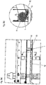
- FIGS. 2a and b further show a connection arrangement with a clamp 1 of the type described above (a spacer abutment was omitted here).
- the connection arrangement further comprises a high voltage line 11 whose outer diameter corresponds to the inner diameter of the ring 5.
- the clamp 1 is attached via a screw 13 to a support 12, which is formed here by a cable tray.
- the cable tray or the distance between the side walls is how FIG. 2b clearly shows, not significantly wider than the transverse dimension of the clamp (dimensions of the clamp in the direction of the plane E).
- the clamp 1 can be fixed in a simple manner on the support 12 on the underside, namely by first a prefixing of the clamp 1 on the line 11 via the aforementioned snap connection and then the clamp 1 attached to the final position within the cable tray 12 by means of the screw 13 becomes.
- the screw 13 is inserted from below through the support 12, then through the opening 2.21 of the first attachment section 2.2, then through the opening 3.21 of the second attachment section 3.2 and finally rotated into the internal thread 7 of the threaded sleeve 8.
Landscapes
- Engineering & Computer Science (AREA)
- General Engineering & Computer Science (AREA)
- Architecture (AREA)
- Civil Engineering (AREA)
- Structural Engineering (AREA)
- Mechanical Engineering (AREA)
- Clamps And Clips (AREA)
Claims (13)
- Agencement de connexion servant à la fixation d'une ligne, en particulier d'une ligne conductrice de courant électrique, sur un véhicule ferroviaire, ledit agencement de connexion comprenant un collier (1) et un support (12) sur lequel est fixé le collier (1),- où le collier (1) comprend un premier élément de collier (2) qui présente une première partie (2.1) en forme de coque et une première partie de fixation (2.2) se raccordant à ladite première partie en forme de coque,- où le collier (1) comprend un second élément de collier (3) qui présente une seconde partie (3.1) en forme de coque et une seconde partie de fixation (3.2) se raccordant à ladite seconde partie en forme de coque,- où le premier et le second élément de collier (2, 3) sont assemblés l'un à l'autre et peuvent pivoter l'un par rapport à l'autre entre une position d'ouverture et une position de fermeture, où la première et la seconde partie (2.1, 3.1) entourent ensemble un espace de logement (6), dans la position de fermeture, et forment un anneau (5) qui entoure l'espace de logement (6),- où la première et la seconde partie de fixation (2.2, 3.2) s'étendent, dans le sens radial, à l'extérieur de l'espace de logement (6) et de l'anneau (5) et sont configurées en pouvant être assemblées l'une à l'autre, et- où la première et la seconde partie de fixation (2.2, 3.2) présentent à chaque fois une ouverture (2.21, 3.21), où les ouvertures (2.21, 3.21) sont alignées l'une par rapport à l'autre dans la position de fermeture,- où il est prévu, sur l'une des parties de fixation (2.2, 3.2), un filetage intérieur (7) disposé de façon coaxiale par rapport à l'ouverture (2.21, 3.21) de cette partie de fixation (2.2, 3.2), et où un moyen de fixation (13) est guidé, à travers des ouvertures (2.21, 3.21) se trouvant dans la première et la seconde partie de fixation (2.2, 3.2), et est vissé avec le filetage intérieur (7) où, en procédant de cette manière, le collier (1) est fixé sur le support (12), de même que les éléments de collier (2, 3) sont, aussi, fixés l'un par rapport à l'autre dans la position de fermeture,- où la première partie de fixation (2.2) présente une partie de montage (2.22) qui comprend une surface de montage (2.221) s'écartant de la seconde partie de fixation (3.2), laquelle surface de montage forme un appui servant à la fixation du collier (1),- où, dans la position de fermeture, une projection de la surface de montage (2.221) coupe l'espace de logement (6) dans une direction perpendiculaire à la surface de montage (2.221), et- où la projection de l'ouverture (2.21) de la première partie de fixation (2.2) coupe l'anneau (5) le long de l'axe médian (M) de ladite ouverture, dans la position de fermeture.
- Agencement de connexion selon la revendication 1, caractérisé en ce que la surface de montage (2.221) de la partie de montage (2.22) de la première partie de fixation (2.2) se trouve dans un plan (E) qui s'étend à l'extérieur de l'anneau (5), dans le sens radial.
- Agencement de connexion selon la revendication 1 ou 2, caractérisé en ce que l'axe médian (M) de l'ouverture (2.21) de la première partie de fixation (2.2) coupe l'anneau (5) dans la position de fermeture.
- Agencement de connexion selon l'une quelconque des revendications précédentes, caractérisé en ce que la partie de fixation, sur laquelle est prévu le filetage intérieur (7), est la seconde partie de fixation (3.2).
- Agencement de connexion selon la revendication 4, caractérisé en ce que le filetage intérieur (7) fait partie de l'ouverture (2.21, 3.21) se trouvant dans la partie de fixation (2.2, 3.2), ou bien le filetage intérieur est prévu dans un manchon fileté (8) qui est disposé sur la partie de fixation (2.2, 3.2).
- Agencement de connexion selon l'une quelconque des revendications précédentes, caractérisé en ce que la première et la seconde partie de fixation (2.2, 3.2) forment ensemble, dans la position de fermeture, un assemblage à encliquetage qui est détachable, en particulier seulement par un mouvement des éléments de collier (2, 3) l'un par rapport à l'autre, passant de la position de fermeture dans la position d'ouverture.
- Agencement de connexion selon l'une quelconque des revendications précédentes, caractérisé en ce que l'une des parties (2.1, 3.1) en forme de coque, en particulier la partie (2.1) en forme de coque du premier élément de collier (2), est reliée à une butée d'espacement (9) qui s'étend à l'extérieur de l'espace de logement (6) dans le sens radial, en particulier à l'extérieur de l'anneau (5) dans le sens radial.
- Agencement de connexion selon l'une quelconque des revendications précédentes, caractérisé en ce que le premier et le second élément de collier (2, 3) sont reliés l'un à l'autre par une charnière (4), où la charnière (4) est formée en particulier par une ouverture (4.1), de préférence par une ouverture (4.1) en forme de fente qui est configurée sur l'extrémité côté charnière de l'un des éléments de collier (2 ; 3), et qui est formée par une languette (4.2) introduite dans l'ouverture (4.1), languette qui est configurée sur l'extrémité côté charnière respectivement de l'autre élément de collier (3 ; 2).
- Agencement de connexion selon la revendication 8, caractérisé en ce que l'espacement, dans la direction circonférentielle, compris entre la charnière (4) et la première partie de fixation (2.2), est plus petit que l'espacement, dans la direction circonférentielle, compris entre la charnière (4) et la seconde partie de fixation (3.2).
- Agencement de connexion selon l'une quelconque des revendications précédentes, caractérisé en ce qu'une pièce intercalaire (10) en matière plastique, en particulier une pièce intercalaire (10) en caoutchouc, vient en appui, côté intérieur dans le sens radial, sur la première partie (2.1) en forme de coque et sur la seconde partie (3.1) en forme de coque, pièce intercalaire en caoutchouc qui passe, en particulier, de la zone de la première partie (2.1) en forme de coque, dans la zone de la seconde partie (3.1) en forme de coque et, de préférence, précontraint les éléments de collier (2, 3) l'un par rapport à l'autre dans la direction de la position de fermeture.
- Agencement de connexion selon l'une quelconque des revendications précédentes, caractérisé en ce que le rapport de la longueur de section maximale, en particulier du diamètre (D), de l'espace de logement (6) et/ou du diamètre intérieur (D) de l'anneau (5), relativement à la largeur (B) de la première et/ou de la seconde partie (2.1, 3.1) en forme de coque, est au maximum égal à 3, de préférence au maximum égal à 2, de façon particulièrement préférable au maximum égal à 1,5.
- Agencement de connexion selon l'une quelconque des revendications précédentes,- où le support (12) délimite un espace de logement de ligne, espace dans lequel le collier (1) peut être logé avec une ligne (11) guidée à travers le collier (1),- où le collier (1) est fixé sur une surface de fixation du support (12), et les parties de fixation (2.2, 3.2) du collier (1) sont disposées entre la surface de fixation et l'espace de logement (6) du collier (1).
- Agencement de connexion selon l'une quelconque des revendications précédentes, caractérisé en ce que le moyen de fixation (13) est guidé, à travers les ouvertures (2.21, 3.21), dans une direction allant de la surface de fixation du support (12) jusqu'à la première partie de fixation (2.2), et ensuite, jusqu'à la seconde partie de fixation (3.2), où le filetage intérieur (7) est prévu en particulier sur la seconde partie de fixation (3.2), de préférence dans un manchon fileté (8) fixé sur la seconde partie de fixation (3.2).
Applications Claiming Priority (1)
| Application Number | Priority Date | Filing Date | Title |
|---|---|---|---|
| DE102014118499.8A DE102014118499B4 (de) | 2014-12-12 | 2014-12-12 | Schelle zur Befestigung einer Leitung, insbesondere stromführenden Leitung, an einem Schienenfahrzeug |
Publications (2)
| Publication Number | Publication Date |
|---|---|
| EP3032154A1 EP3032154A1 (fr) | 2016-06-15 |
| EP3032154B1 true EP3032154B1 (fr) | 2018-06-27 |
Family
ID=54848412
Family Applications (1)
| Application Number | Title | Priority Date | Filing Date |
|---|---|---|---|
| EP15198580.1A Active EP3032154B1 (fr) | 2014-12-12 | 2015-12-09 | Ensemble de connexion avec un collier et un support pour la fixation d'une ligne, en particulier une ligne electrique, sur un vehicule ferroviaire |
Country Status (2)
| Country | Link |
|---|---|
| EP (1) | EP3032154B1 (fr) |
| DE (1) | DE102014118499B4 (fr) |
Families Citing this family (3)
| Publication number | Priority date | Publication date | Assignee | Title |
|---|---|---|---|---|
| DE102016112758B4 (de) * | 2016-07-12 | 2020-06-18 | Lisa Dräxlmaier GmbH | Halteteil und verfahren zum befestigen von elektrischen leitungen sowie leitungsanordnung in einem fahrzeug |
| CN110336234A (zh) * | 2019-08-07 | 2019-10-15 | 沈阳飞机工业(集团)有限公司 | 一种线束敷设快速定位调整装置及其使用方法 |
| CN111416312B (zh) * | 2020-04-16 | 2025-09-09 | 格力电器(重庆)有限公司 | 一种固线夹组件以及电器盒 |
Family Cites Families (13)
| Publication number | Priority date | Publication date | Assignee | Title |
|---|---|---|---|---|
| GB239390A (en) * | 1924-10-24 | 1925-09-10 | Arthur Henry Barker | Improved means for attaching pipes to walls |
| DE811763C (de) * | 1948-10-02 | 1952-05-08 | Maria Dax | Rohrschelle |
| DE8323916U1 (de) * | 1983-08-18 | 1983-12-08 | Puk-Werke Kg Kunststoff-Stahlverarbeitung Gmbh & Co, 1000 Berlin | Kabeltragwanne |
| DE3808334C1 (en) * | 1988-03-12 | 1989-08-24 | Rasmussen Gmbh, 6457 Maintal, De | Clamp for fastening a pipe |
| DE9104130U1 (de) * | 1991-04-05 | 1991-05-29 | OBO Bettermann oHG, 5750 Menden | Rohrschelle aus Metall |
| DE9402626U1 (de) * | 1994-02-17 | 1994-04-21 | Saxonia-Franke GmbH & Co, 73037 Göppingen | Befestigungsclip für Leitungen, Kabel o.dgl. |
| SE510015C2 (sv) * | 1996-11-01 | 1999-04-12 | Isco Ab | Monteringsklämma |
| JP3870329B2 (ja) * | 1997-02-25 | 2007-01-17 | 日本機電株式会社 | 鋼管緊結金具 |
| DE10023126A1 (de) * | 2000-05-11 | 2001-11-29 | Hydac Befestigungstechnik Gmbh | Schelle zur Befestigung von Schlauch-oder Rohrleitungen |
| DE102006025793A1 (de) * | 2006-06-02 | 2007-12-06 | Contitech Techno-Chemie Gmbh | Halterung für eine Rohrleitung |
| DE102009019670A1 (de) * | 2009-04-30 | 2011-01-05 | Hydac Accessories Gmbh | Schelle |
| DE102010022248B4 (de) * | 2010-05-31 | 2016-04-14 | Schwing Gmbh | Mastaufbau für eine Betonfördervorrichtung |
| FR2974878A1 (fr) * | 2011-05-05 | 2012-11-09 | Caillau Ets | Collier de serrage a charniere |
-
2014
- 2014-12-12 DE DE102014118499.8A patent/DE102014118499B4/de active Active
-
2015
- 2015-12-09 EP EP15198580.1A patent/EP3032154B1/fr active Active
Non-Patent Citations (1)
| Title |
|---|
| None * |
Also Published As
| Publication number | Publication date |
|---|---|
| DE102014118499B4 (de) | 2021-03-25 |
| DE102014118499A1 (de) | 2016-06-16 |
| EP3032154A1 (fr) | 2016-06-15 |
Similar Documents
| Publication | Publication Date | Title |
|---|---|---|
| DE3503293C2 (fr) | ||
| WO2019115100A1 (fr) | Clip de montage | |
| EP3433912B1 (fr) | Un support de pièce plate pour fixer une pièce plate à un cadre d'une armoire électrique et armoire électrique correspondante | |
| DE202011050310U1 (de) | Abgewinkelte Midi- oder Schmelzsicherung | |
| EP3406501B1 (fr) | Véhicule pourvu d'au moins un dispositif de canal et procédé permettant d'équiper un véhicule d'un dispositif de canal | |
| EP3032154B1 (fr) | Ensemble de connexion avec un collier et un support pour la fixation d'une ligne, en particulier une ligne electrique, sur un vehicule ferroviaire | |
| EP3789280A1 (fr) | Élément de console, système pourvu d'élément de console et procédé de liaison d'un élément de console à un plancher d'un véhicule | |
| EP3374234B1 (fr) | Système de fixation | |
| EP2873874B1 (fr) | Agencement pour la fixation d'un équipement d'intérieur d'un véhicule automobile | |
| EP2869417B1 (fr) | Dispositif de liaison de sections de conduit de câble et conduit de câble | |
| EP3740399B1 (fr) | Attache et ensemble support de fil de contact | |
| EP0139980B1 (fr) | Cable clamp | |
| DE202010010424U1 (de) | Wanddurchführungsklemme für elektrische Leiter | |
| DE102010002634B4 (de) | Befestigungsanordnung für Kabelführungen | |
| EP2177694A2 (fr) | Pince de clôture pour la fixation d'une grille de clôture sur un poteau | |
| EP3071896A1 (fr) | Dispositif de retenue pour boîtier et procédé de montage du boîtier à l'aide du dispositif de retenue | |
| EP3658787B1 (fr) | Composant moulé, procédé servant à assembler au moins un composant en tôle à un composant moulé, et système de construction d'une tôle | |
| EP2339710A2 (fr) | Appareil d'installation électrique | |
| EP2403084A2 (fr) | Guidage de câble et de conduite | |
| EP2124308B1 (fr) | Appareil d'installation électrique | |
| EP3618208A1 (fr) | Conduit de câbles et dispositif de raccordement de sections de conduit de câbles | |
| EP3772778B1 (fr) | Système porteur permettant de fixer un objet oblong ainsi qu'élément rapporté formant agrafe | |
| EP3740398B1 (fr) | Bride de suspension pour lignes aériennes gauchies l'une par rapport à l'autre | |
| EP3050177A1 (fr) | Dispositif boîtier pour une borne de connexion électrique et borne de connexion électrique correspondante | |
| EP3628450B1 (fr) | Dispositif de fixation mécanique d'au moins un connecteur adaptateur à un boîtier |
Legal Events
| Date | Code | Title | Description |
|---|---|---|---|
| PUAI | Public reference made under article 153(3) epc to a published international application that has entered the european phase |
Free format text: ORIGINAL CODE: 0009012 |
|
| AK | Designated contracting states |
Kind code of ref document: A1 Designated state(s): AL AT BE BG CH CY CZ DE DK EE ES FI FR GB GR HR HU IE IS IT LI LT LU LV MC MK MT NL NO PL PT RO RS SE SI SK SM TR |
|
| AX | Request for extension of the european patent |
Extension state: BA ME |
|
| 17P | Request for examination filed |
Effective date: 20160804 |
|
| RBV | Designated contracting states (corrected) |
Designated state(s): AL AT BE BG CH CY CZ DE DK EE ES FI FR GB GR HR HU IE IS IT LI LT LU LV MC MK MT NL NO PL PT RO RS SE SI SK SM TR |
|
| 17Q | First examination report despatched |
Effective date: 20170321 |
|
| GRAP | Despatch of communication of intention to grant a patent |
Free format text: ORIGINAL CODE: EPIDOSNIGR1 |
|
| INTG | Intention to grant announced |
Effective date: 20180124 |
|
| GRAS | Grant fee paid |
Free format text: ORIGINAL CODE: EPIDOSNIGR3 |
|
| GRAA | (expected) grant |
Free format text: ORIGINAL CODE: 0009210 |
|
| AK | Designated contracting states |
Kind code of ref document: B1 Designated state(s): AL AT BE BG CH CY CZ DE DK EE ES FI FR GB GR HR HU IE IS IT LI LT LU LV MC MK MT NL NO PL PT RO RS SE SI SK SM TR |
|
| RAP1 | Party data changed (applicant data changed or rights of an application transferred) |
Owner name: BOMBARDIER TRANSPORTATION GMBH |
|
| REG | Reference to a national code |
Ref country code: GB Ref legal event code: FG4D Free format text: NOT ENGLISH |
|
| REG | Reference to a national code |
Ref country code: AT Ref legal event code: REF Ref document number: 1012645 Country of ref document: AT Kind code of ref document: T Effective date: 20180715 |
|
| REG | Reference to a national code |
Ref country code: IE Ref legal event code: FG4D Free format text: LANGUAGE OF EP DOCUMENT: GERMAN |
|
| REG | Reference to a national code |
Ref country code: DE Ref legal event code: R096 Ref document number: 502015004819 Country of ref document: DE |
|
| PG25 | Lapsed in a contracting state [announced via postgrant information from national office to epo] |
Ref country code: BG Free format text: LAPSE BECAUSE OF FAILURE TO SUBMIT A TRANSLATION OF THE DESCRIPTION OR TO PAY THE FEE WITHIN THE PRESCRIBED TIME-LIMIT Effective date: 20180927 Ref country code: NO Free format text: LAPSE BECAUSE OF FAILURE TO SUBMIT A TRANSLATION OF THE DESCRIPTION OR TO PAY THE FEE WITHIN THE PRESCRIBED TIME-LIMIT Effective date: 20180927 Ref country code: FI Free format text: LAPSE BECAUSE OF FAILURE TO SUBMIT A TRANSLATION OF THE DESCRIPTION OR TO PAY THE FEE WITHIN THE PRESCRIBED TIME-LIMIT Effective date: 20180627 Ref country code: SE Free format text: LAPSE BECAUSE OF FAILURE TO SUBMIT A TRANSLATION OF THE DESCRIPTION OR TO PAY THE FEE WITHIN THE PRESCRIBED TIME-LIMIT Effective date: 20180627 Ref country code: LT Free format text: LAPSE BECAUSE OF FAILURE TO SUBMIT A TRANSLATION OF THE DESCRIPTION OR TO PAY THE FEE WITHIN THE PRESCRIBED TIME-LIMIT Effective date: 20180627 |
|
| REG | Reference to a national code |
Ref country code: NL Ref legal event code: MP Effective date: 20180627 |
|
| REG | Reference to a national code |
Ref country code: LT Ref legal event code: MG4D |
|
| PG25 | Lapsed in a contracting state [announced via postgrant information from national office to epo] |
Ref country code: RS Free format text: LAPSE BECAUSE OF FAILURE TO SUBMIT A TRANSLATION OF THE DESCRIPTION OR TO PAY THE FEE WITHIN THE PRESCRIBED TIME-LIMIT Effective date: 20180627 Ref country code: HR Free format text: LAPSE BECAUSE OF FAILURE TO SUBMIT A TRANSLATION OF THE DESCRIPTION OR TO PAY THE FEE WITHIN THE PRESCRIBED TIME-LIMIT Effective date: 20180627 Ref country code: GR Free format text: LAPSE BECAUSE OF FAILURE TO SUBMIT A TRANSLATION OF THE DESCRIPTION OR TO PAY THE FEE WITHIN THE PRESCRIBED TIME-LIMIT Effective date: 20180928 Ref country code: LV Free format text: LAPSE BECAUSE OF FAILURE TO SUBMIT A TRANSLATION OF THE DESCRIPTION OR TO PAY THE FEE WITHIN THE PRESCRIBED TIME-LIMIT Effective date: 20180627 |
|
| PG25 | Lapsed in a contracting state [announced via postgrant information from national office to epo] |
Ref country code: NL Free format text: LAPSE BECAUSE OF FAILURE TO SUBMIT A TRANSLATION OF THE DESCRIPTION OR TO PAY THE FEE WITHIN THE PRESCRIBED TIME-LIMIT Effective date: 20180627 |
|
| PG25 | Lapsed in a contracting state [announced via postgrant information from national office to epo] |
Ref country code: SK Free format text: LAPSE BECAUSE OF FAILURE TO SUBMIT A TRANSLATION OF THE DESCRIPTION OR TO PAY THE FEE WITHIN THE PRESCRIBED TIME-LIMIT Effective date: 20180627 Ref country code: RO Free format text: LAPSE BECAUSE OF FAILURE TO SUBMIT A TRANSLATION OF THE DESCRIPTION OR TO PAY THE FEE WITHIN THE PRESCRIBED TIME-LIMIT Effective date: 20180627 Ref country code: CZ Free format text: LAPSE BECAUSE OF FAILURE TO SUBMIT A TRANSLATION OF THE DESCRIPTION OR TO PAY THE FEE WITHIN THE PRESCRIBED TIME-LIMIT Effective date: 20180627 Ref country code: IS Free format text: LAPSE BECAUSE OF FAILURE TO SUBMIT A TRANSLATION OF THE DESCRIPTION OR TO PAY THE FEE WITHIN THE PRESCRIBED TIME-LIMIT Effective date: 20181027 Ref country code: EE Free format text: LAPSE BECAUSE OF FAILURE TO SUBMIT A TRANSLATION OF THE DESCRIPTION OR TO PAY THE FEE WITHIN THE PRESCRIBED TIME-LIMIT Effective date: 20180627 Ref country code: PL Free format text: LAPSE BECAUSE OF FAILURE TO SUBMIT A TRANSLATION OF THE DESCRIPTION OR TO PAY THE FEE WITHIN THE PRESCRIBED TIME-LIMIT Effective date: 20180627 |
|
| PG25 | Lapsed in a contracting state [announced via postgrant information from national office to epo] |
Ref country code: IT Free format text: LAPSE BECAUSE OF FAILURE TO SUBMIT A TRANSLATION OF THE DESCRIPTION OR TO PAY THE FEE WITHIN THE PRESCRIBED TIME-LIMIT Effective date: 20180627 Ref country code: SM Free format text: LAPSE BECAUSE OF FAILURE TO SUBMIT A TRANSLATION OF THE DESCRIPTION OR TO PAY THE FEE WITHIN THE PRESCRIBED TIME-LIMIT Effective date: 20180627 Ref country code: ES Free format text: LAPSE BECAUSE OF FAILURE TO SUBMIT A TRANSLATION OF THE DESCRIPTION OR TO PAY THE FEE WITHIN THE PRESCRIBED TIME-LIMIT Effective date: 20180627 |
|
| REG | Reference to a national code |
Ref country code: DE Ref legal event code: R097 Ref document number: 502015004819 Country of ref document: DE |
|
| PLBE | No opposition filed within time limit |
Free format text: ORIGINAL CODE: 0009261 |
|
| STAA | Information on the status of an ep patent application or granted ep patent |
Free format text: STATUS: NO OPPOSITION FILED WITHIN TIME LIMIT |
|
| PG25 | Lapsed in a contracting state [announced via postgrant information from national office to epo] |
Ref country code: DK Free format text: LAPSE BECAUSE OF FAILURE TO SUBMIT A TRANSLATION OF THE DESCRIPTION OR TO PAY THE FEE WITHIN THE PRESCRIBED TIME-LIMIT Effective date: 20180627 |
|
| 26N | No opposition filed |
Effective date: 20190328 |
|
| REG | Reference to a national code |
Ref country code: CH Ref legal event code: PL |
|
| PG25 | Lapsed in a contracting state [announced via postgrant information from national office to epo] |
Ref country code: SI Free format text: LAPSE BECAUSE OF FAILURE TO SUBMIT A TRANSLATION OF THE DESCRIPTION OR TO PAY THE FEE WITHIN THE PRESCRIBED TIME-LIMIT Effective date: 20180627 Ref country code: MC Free format text: LAPSE BECAUSE OF FAILURE TO SUBMIT A TRANSLATION OF THE DESCRIPTION OR TO PAY THE FEE WITHIN THE PRESCRIBED TIME-LIMIT Effective date: 20180627 Ref country code: LU Free format text: LAPSE BECAUSE OF NON-PAYMENT OF DUE FEES Effective date: 20181209 |
|
| REG | Reference to a national code |
Ref country code: IE Ref legal event code: MM4A |
|
| REG | Reference to a national code |
Ref country code: BE Ref legal event code: MM Effective date: 20181231 |
|
| PG25 | Lapsed in a contracting state [announced via postgrant information from national office to epo] |
Ref country code: IE Free format text: LAPSE BECAUSE OF NON-PAYMENT OF DUE FEES Effective date: 20181209 |
|
| PG25 | Lapsed in a contracting state [announced via postgrant information from national office to epo] |
Ref country code: AL Free format text: LAPSE BECAUSE OF FAILURE TO SUBMIT A TRANSLATION OF THE DESCRIPTION OR TO PAY THE FEE WITHIN THE PRESCRIBED TIME-LIMIT Effective date: 20180627 Ref country code: BE Free format text: LAPSE BECAUSE OF NON-PAYMENT OF DUE FEES Effective date: 20181231 |
|
| PG25 | Lapsed in a contracting state [announced via postgrant information from national office to epo] |
Ref country code: CH Free format text: LAPSE BECAUSE OF NON-PAYMENT OF DUE FEES Effective date: 20181231 Ref country code: LI Free format text: LAPSE BECAUSE OF NON-PAYMENT OF DUE FEES Effective date: 20181231 |
|
| PG25 | Lapsed in a contracting state [announced via postgrant information from national office to epo] |
Ref country code: MT Free format text: LAPSE BECAUSE OF FAILURE TO SUBMIT A TRANSLATION OF THE DESCRIPTION OR TO PAY THE FEE WITHIN THE PRESCRIBED TIME-LIMIT Effective date: 20180627 |
|
| PG25 | Lapsed in a contracting state [announced via postgrant information from national office to epo] |
Ref country code: TR Free format text: LAPSE BECAUSE OF FAILURE TO SUBMIT A TRANSLATION OF THE DESCRIPTION OR TO PAY THE FEE WITHIN THE PRESCRIBED TIME-LIMIT Effective date: 20180627 |
|
| PG25 | Lapsed in a contracting state [announced via postgrant information from national office to epo] |
Ref country code: PT Free format text: LAPSE BECAUSE OF FAILURE TO SUBMIT A TRANSLATION OF THE DESCRIPTION OR TO PAY THE FEE WITHIN THE PRESCRIBED TIME-LIMIT Effective date: 20180627 |
|
| PG25 | Lapsed in a contracting state [announced via postgrant information from national office to epo] |
Ref country code: CY Free format text: LAPSE BECAUSE OF FAILURE TO SUBMIT A TRANSLATION OF THE DESCRIPTION OR TO PAY THE FEE WITHIN THE PRESCRIBED TIME-LIMIT Effective date: 20180627 Ref country code: HU Free format text: LAPSE BECAUSE OF FAILURE TO SUBMIT A TRANSLATION OF THE DESCRIPTION OR TO PAY THE FEE WITHIN THE PRESCRIBED TIME-LIMIT; INVALID AB INITIO Effective date: 20151209 Ref country code: MK Free format text: LAPSE BECAUSE OF NON-PAYMENT OF DUE FEES Effective date: 20180627 |
|
| GBPC | Gb: european patent ceased through non-payment of renewal fee |
Effective date: 20191209 |
|
| PG25 | Lapsed in a contracting state [announced via postgrant information from national office to epo] |
Ref country code: GB Free format text: LAPSE BECAUSE OF NON-PAYMENT OF DUE FEES Effective date: 20191209 |
|
| P01 | Opt-out of the competence of the unified patent court (upc) registered |
Effective date: 20230822 |
|
| PGFP | Annual fee paid to national office [announced via postgrant information from national office to epo] |
Ref country code: DE Payment date: 20251211 Year of fee payment: 11 |
|
| PGFP | Annual fee paid to national office [announced via postgrant information from national office to epo] |
Ref country code: AT Payment date: 20251222 Year of fee payment: 11 |
|
| PGFP | Annual fee paid to national office [announced via postgrant information from national office to epo] |
Ref country code: FR Payment date: 20251223 Year of fee payment: 11 |