EP3406817A1 - Metallbeschichtete dachunterspannbahn - Google Patents
Metallbeschichtete dachunterspannbahn Download PDFInfo
- Publication number
- EP3406817A1 EP3406817A1 EP18171232.4A EP18171232A EP3406817A1 EP 3406817 A1 EP3406817 A1 EP 3406817A1 EP 18171232 A EP18171232 A EP 18171232A EP 3406817 A1 EP3406817 A1 EP 3406817A1
- Authority
- EP
- European Patent Office
- Prior art keywords
- layer
- metal coating
- sealing layer
- cover layer
- sealing
- Prior art date
- Legal status (The legal status is an assumption and is not a legal conclusion. Google has not performed a legal analysis and makes no representation as to the accuracy of the status listed.)
- Granted
Links
Images
Classifications
-
- E—FIXED CONSTRUCTIONS
- E04—BUILDING
- E04D—ROOF COVERINGS; SKY-LIGHTS; GUTTERS; ROOF-WORKING TOOLS
- E04D12/00—Non-structural supports for roofing materials, e.g. battens, boards
- E04D12/002—Sheets of flexible material, e.g. roofing tile underlay
-
- B—PERFORMING OPERATIONS; TRANSPORTING
- B32—LAYERED PRODUCTS
- B32B—LAYERED PRODUCTS, i.e. PRODUCTS BUILT-UP OF STRATA OF FLAT OR NON-FLAT, e.g. CELLULAR OR HONEYCOMB, FORM
- B32B15/00—Layered products comprising a layer of metal
- B32B15/14—Layered products comprising a layer of metal next to a fibrous or filamentary layer
-
- B—PERFORMING OPERATIONS; TRANSPORTING
- B32—LAYERED PRODUCTS
- B32B—LAYERED PRODUCTS, i.e. PRODUCTS BUILT-UP OF STRATA OF FLAT OR NON-FLAT, e.g. CELLULAR OR HONEYCOMB, FORM
- B32B27/00—Layered products comprising a layer of synthetic resin
- B32B27/06—Layered products comprising a layer of synthetic resin as the main or only constituent of a layer, which is next to another layer of the same or of a different material
- B32B27/08—Layered products comprising a layer of synthetic resin as the main or only constituent of a layer, which is next to another layer of the same or of a different material of synthetic resin
-
- B—PERFORMING OPERATIONS; TRANSPORTING
- B32—LAYERED PRODUCTS
- B32B—LAYERED PRODUCTS, i.e. PRODUCTS BUILT-UP OF STRATA OF FLAT OR NON-FLAT, e.g. CELLULAR OR HONEYCOMB, FORM
- B32B27/00—Layered products comprising a layer of synthetic resin
- B32B27/12—Layered products comprising a layer of synthetic resin next to a fibrous or filamentary layer
-
- B—PERFORMING OPERATIONS; TRANSPORTING
- B32—LAYERED PRODUCTS
- B32B—LAYERED PRODUCTS, i.e. PRODUCTS BUILT-UP OF STRATA OF FLAT OR NON-FLAT, e.g. CELLULAR OR HONEYCOMB, FORM
- B32B27/00—Layered products comprising a layer of synthetic resin
- B32B27/32—Layered products comprising a layer of synthetic resin comprising polyolefins
-
- B—PERFORMING OPERATIONS; TRANSPORTING
- B32—LAYERED PRODUCTS
- B32B—LAYERED PRODUCTS, i.e. PRODUCTS BUILT-UP OF STRATA OF FLAT OR NON-FLAT, e.g. CELLULAR OR HONEYCOMB, FORM
- B32B3/00—Layered products comprising a layer with external or internal discontinuities or unevennesses, or a layer of non-planar shape; Layered products comprising a layer having particular features of form
- B32B3/26—Layered products comprising a layer with external or internal discontinuities or unevennesses, or a layer of non-planar shape; Layered products comprising a layer having particular features of form characterised by a particular shape of the outline of the cross-section of a continuous layer; characterised by a layer with cavities or internal voids ; characterised by an apertured layer
- B32B3/266—Layered products comprising a layer with external or internal discontinuities or unevennesses, or a layer of non-planar shape; Layered products comprising a layer having particular features of form characterised by a particular shape of the outline of the cross-section of a continuous layer; characterised by a layer with cavities or internal voids ; characterised by an apertured layer characterised by an apertured layer, the apertures going through the whole thickness of the layer, e.g. expanded metal, perforated layer, slit layer regular cells B32B3/12
-
- B—PERFORMING OPERATIONS; TRANSPORTING
- B32—LAYERED PRODUCTS
- B32B—LAYERED PRODUCTS, i.e. PRODUCTS BUILT-UP OF STRATA OF FLAT OR NON-FLAT, e.g. CELLULAR OR HONEYCOMB, FORM
- B32B5/00—Layered products characterised by the non- homogeneity or physical structure, i.e. comprising a fibrous, filamentary, particulate or foam layer; Layered products characterised by having a layer differing constitutionally or physically in different parts
- B32B5/02—Layered products characterised by the non- homogeneity or physical structure, i.e. comprising a fibrous, filamentary, particulate or foam layer; Layered products characterised by having a layer differing constitutionally or physically in different parts characterised by structural features of a fibrous or filamentary layer
- B32B5/022—Non-woven fabric
-
- B—PERFORMING OPERATIONS; TRANSPORTING
- B32—LAYERED PRODUCTS
- B32B—LAYERED PRODUCTS, i.e. PRODUCTS BUILT-UP OF STRATA OF FLAT OR NON-FLAT, e.g. CELLULAR OR HONEYCOMB, FORM
- B32B7/00—Layered products characterised by the relation between layers; Layered products characterised by the relative orientation of features between layers, or by the relative values of a measurable parameter between layers, i.e. products comprising layers having different physical, chemical or physicochemical properties; Layered products characterised by the interconnection of layers
- B32B7/04—Interconnection of layers
- B32B7/12—Interconnection of layers using interposed adhesives or interposed materials with bonding properties
-
- E—FIXED CONSTRUCTIONS
- E04—BUILDING
- E04D—ROOF COVERINGS; SKY-LIGHTS; GUTTERS; ROOF-WORKING TOOLS
- E04D5/00—Roof covering by making use of flexible material, e.g. supplied in roll form
- E04D5/10—Roof covering by making use of flexible material, e.g. supplied in roll form by making use of compounded or laminated materials, e.g. metal foils or plastic films coated with bitumen
-
- B—PERFORMING OPERATIONS; TRANSPORTING
- B32—LAYERED PRODUCTS
- B32B—LAYERED PRODUCTS, i.e. PRODUCTS BUILT-UP OF STRATA OF FLAT OR NON-FLAT, e.g. CELLULAR OR HONEYCOMB, FORM
- B32B2255/00—Coating on the layer surface
- B32B2255/10—Coating on the layer surface on synthetic resin layer or on natural or synthetic rubber layer
-
- B—PERFORMING OPERATIONS; TRANSPORTING
- B32—LAYERED PRODUCTS
- B32B—LAYERED PRODUCTS, i.e. PRODUCTS BUILT-UP OF STRATA OF FLAT OR NON-FLAT, e.g. CELLULAR OR HONEYCOMB, FORM
- B32B2255/00—Coating on the layer surface
- B32B2255/20—Inorganic coating
- B32B2255/205—Metallic coating
-
- B—PERFORMING OPERATIONS; TRANSPORTING
- B32—LAYERED PRODUCTS
- B32B—LAYERED PRODUCTS, i.e. PRODUCTS BUILT-UP OF STRATA OF FLAT OR NON-FLAT, e.g. CELLULAR OR HONEYCOMB, FORM
- B32B2262/00—Composition or structural features of fibres which form a fibrous or filamentary layer or are present as additives
- B32B2262/02—Synthetic macromolecular fibres
- B32B2262/0253—Polyolefin fibres
-
- B—PERFORMING OPERATIONS; TRANSPORTING
- B32—LAYERED PRODUCTS
- B32B—LAYERED PRODUCTS, i.e. PRODUCTS BUILT-UP OF STRATA OF FLAT OR NON-FLAT, e.g. CELLULAR OR HONEYCOMB, FORM
- B32B2307/00—Properties of the layers or laminate
- B32B2307/40—Properties of the layers or laminate having particular optical properties
-
- B—PERFORMING OPERATIONS; TRANSPORTING
- B32—LAYERED PRODUCTS
- B32B—LAYERED PRODUCTS, i.e. PRODUCTS BUILT-UP OF STRATA OF FLAT OR NON-FLAT, e.g. CELLULAR OR HONEYCOMB, FORM
- B32B2307/00—Properties of the layers or laminate
- B32B2307/50—Properties of the layers or laminate having particular mechanical properties
- B32B2307/514—Oriented
- B32B2307/516—Oriented mono-axially
-
- B—PERFORMING OPERATIONS; TRANSPORTING
- B32—LAYERED PRODUCTS
- B32B—LAYERED PRODUCTS, i.e. PRODUCTS BUILT-UP OF STRATA OF FLAT OR NON-FLAT, e.g. CELLULAR OR HONEYCOMB, FORM
- B32B2307/00—Properties of the layers or laminate
- B32B2307/50—Properties of the layers or laminate having particular mechanical properties
- B32B2307/514—Oriented
- B32B2307/518—Oriented bi-axially
-
- B—PERFORMING OPERATIONS; TRANSPORTING
- B32—LAYERED PRODUCTS
- B32B—LAYERED PRODUCTS, i.e. PRODUCTS BUILT-UP OF STRATA OF FLAT OR NON-FLAT, e.g. CELLULAR OR HONEYCOMB, FORM
- B32B2307/00—Properties of the layers or laminate
- B32B2307/70—Other properties
- B32B2307/71—Resistive to light or to UV
-
- B—PERFORMING OPERATIONS; TRANSPORTING
- B32—LAYERED PRODUCTS
- B32B—LAYERED PRODUCTS, i.e. PRODUCTS BUILT-UP OF STRATA OF FLAT OR NON-FLAT, e.g. CELLULAR OR HONEYCOMB, FORM
- B32B2307/00—Properties of the layers or laminate
- B32B2307/70—Other properties
- B32B2307/724—Permeability to gases, adsorption
-
- B—PERFORMING OPERATIONS; TRANSPORTING
- B32—LAYERED PRODUCTS
- B32B—LAYERED PRODUCTS, i.e. PRODUCTS BUILT-UP OF STRATA OF FLAT OR NON-FLAT, e.g. CELLULAR OR HONEYCOMB, FORM
- B32B2307/00—Properties of the layers or laminate
- B32B2307/70—Other properties
- B32B2307/732—Dimensional properties
-
- B—PERFORMING OPERATIONS; TRANSPORTING
- B32—LAYERED PRODUCTS
- B32B—LAYERED PRODUCTS, i.e. PRODUCTS BUILT-UP OF STRATA OF FLAT OR NON-FLAT, e.g. CELLULAR OR HONEYCOMB, FORM
- B32B2419/00—Buildings or parts thereof
- B32B2419/06—Roofs, roof membranes
Definitions
- the invention relates to a laminar structure for use as a roof underlayment, consisting of a base layer and a cover layer and a sealing layer arranged between the base layer and cover layer.
- Roof underlays usually have a multilayer structure.
- a functional film which may be a polyolefin film, has pores in the micrometer range, with the pore size and pore density selected so that the functional film is water vapor permeable but impermeable to liquid water.
- the functional film is sealed on both sides with fleece layers.
- the EP 1 930 363 A2 describes a metal-coated film, wherein the film for electromagnetic radiation in the wavelength range of 1 to 18 GHz has a damping effect.
- the mean pore size of the functional film is 0.1 to 5 ⁇ m.
- the metallization of roof underlays has the advantage that the outwardly facing metal coating reflects infrared light, so that in summer the heat input is reduced by the roof underlayment in the underlying roof.
- a metal-coated roof underlayment has the disadvantage that during laying the metal coating can be damaged or rubbed off.
- the reflection of visible light by the metal coating complicates the laying work, since it unfolds a dazzling effect for the processor.
- the invention has for its object to further develop a generic roof underlay Nutzsvorteilhaft.
- the layer structure has a multilayer structure. Between a base layer and a cover layer extends a functional film, which forms a sealing layer which is waterproof, but also permeable to water vapor. According to the invention, this sealing layer is coated with a metal coating.
- the metal may be aluminum.
- the metal can be vapor-deposited directly onto the sealing layer.
- the sealing layer is a microporous film having a pore size of 0.5 to 5 microns, wherein the layer thickness of the metal coating is smaller than the average pore size.
- the layer thickness can be between 20 and 80 nm, preferably about 50 nm.
- the metal layer applied in particular directly to the sealing layer according to the invention has no free surface. It is rather covered by the cover layer.
- the cover protects the metal coating against mechanical damage and especially against abrasion.
- the cover layer moreover preferably also has an optical filter function. It acts as a low-pass filter. While infrared light passes largely through the capping layer but is reflected on the metal coating, the capping layer is only slightly transmissive to UV light and / or visible light.
- the cover layer can also be in
- the support layer may perform the function of a low-pass filter, which transmits ultraviolet light or visible light only slightly, but is transparent to infrared light.
- the cover layer and / or the support layer may be a nonwoven.
- the fleece is preferably made of polypropylene.
- the cover layer is thermally bonded to the coating or the sealing layer at bonding points. The connection can also be made via an adhesive which is applied locally, for example in thin threads, to the metal layer.
- the support layer can be connected to the sealing layer.
- connection can be made by a thermal bonding method using a calender.
- the microporous sealing layer may consist of polyolefin, in particular of polyethylene or polypropylene. It can have a material thickness between 20 and 30 microns.
- the mechanical connection of the layers of the layer structure takes place via a local heating with a surface-structured calender roll. The layers of the layer structure are selectively heated or pressed against each other. In the area of the metal coating, this can have the consequence that the metal coating is slightly destroyed by melting or melting, so that a direct connection between the sealing layer and the covering layer takes place. Sealing layer and covering layer can thus also be selectively connected to one another in a materially bonded manner.
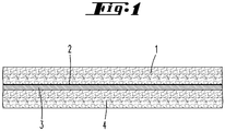
- FIG. 1 shows the cross section through a roof underlay.
- the drawing shows the cross section through the structure according to the invention, designed as a roof underlay or other building foil structure, which is a flat layer structure, which is intended in particular for resting on roof substructures or roof insulation.
- the roof underlayment shown in the embodiment has a support layer 4, on which there is a sealing layer 3, which is provided with a metal coating 2.
- a cover layer 1 is applied on the metal coating 2.
- the roof underlay is in the installed state part of a roof, wherein the support layer 4 has the roof substructure or to a roof insulation.
- the base layer 4 can be applied in particular to a battens.
- the cover layer 1 the roof skin is applied.
- roof battens can be mounted on the cover layer 1, to which roof tiles, in particular roof tiles, are fastened, so that the cover layer 1 faces the roof tiles.
- the support layer 4 consists of a polypropylene film with a material thickness of about 0.3 to 0.5 mm.
- the base layer 4 may be connected to the sealing layer 3 via a thermal bonding method.
- the compound can also be achieved by a hotmelt adhesive, wherein the hotmelt adhesive is applied in such a way that the sealing layer 3 retains its inherently water vapor permeable property and water impermeable property.
- the sealing layer 3 is preferably a microporous film and has a material thickness of 20 to 30 microns. It may consist of a polyolefin, for example. Polyethylene or polypropylene.
- the sealing layer 3 is rendered permeable to water vapor in a known manner by admixing the film with hard material particles during its production and then by stretching the film monoaxially or biaxially.
- the sealing layer 3 has a metal coating 2.
- the metal coating 2 is a vapor-deposited coating of aluminum.
- the layer thickness of the metal coating 2 is less than the mean pore size of the sealing layer 3.
- the average pore size can be between 0.1 and 5 microns.
- the thickness of the metal coating 2 is 20 to 80 nm, and preferably about 50 nm.
- the cover layer is preferably a nonwoven, in particular a polypropylene nonwoven with a layer thickness of 0.3 to 0.5 mm.
- the covering layer 1 can be connected to the metal coating 2 by thermal bonding or by means of a hotmelt adhesive. Again, the connection points between the cover layer 1 and metal coating 2 are limited to local areas, so that the water vapor permeability of the sealing layer 3 is not affected. The water vapor permeability is also not affected by the metal coating 2, since the metal coating 2 is substantially thinner than the average pore size of the sealing layer 3.
- the cover layer 1 may also be selectively connected directly to the sealing layer 3, so that the sealing layer 3 with the cover layer. 1 is anchored.
- the covering layer 1 and possibly the supporting layer 4 are substantially permeable to infrared light. They have low visible light transmittance and / or ultraviolet light transmittance.
- the infrared light passing through the cover layer 1 or base layer 4 acting as a bandpass filter is reflected at the metal coating 2.
- Slight visible light passing through the covering layer 1 and UV light passing through the covering layer 1 are also reflected on the metal coating 2.
- the metal coating 2 thus fulfills two tasks: it prevents heat from passing from the outside into the roof interior, by reflecting infrared radiation. It protects the sealing layer 3 from aging caused by UV irradiation, since it also reflects UV light passing through the covering layer 1.
- the covering layer 1 also fulfills a double function: it protects the metal coating 2 against mechanical damage during installation, for example against abrasion. It also avoids that the metal layer 2 unfolds a dazzling effect by preventing the passage of visible light through the cover layer 1 as far as possible.
- the metal layer 2 may be made thinner due to their inventive arrangement, as they should have been if they were located on the visible surface of a roof underlay.
- a nonwoven material can be used, which has a particularly high permeability to infrared radiation.
- the infrared light is reflected on the metal layer 1 without the disturbing glare effect for the processor. It is therefore of particular advantage if the metal layer between the microporous film formed by the sealant layer 3 and a nonwoven fabric formed by the cover layer 1.
- a laminar layer structure which is characterized in that the sealing layer 3 has a metal coating 2 on its side facing the covering layer 4.
- a flat layer structure which is characterized by the use as a roof underlay, consisting of a base layer 4 and a covering layer 1 and a sealing layer 3 arranged between base layer 4 and covering layer 1, wherein the sealing layer 3 has a metal coating 2 on one of its sides and the covering layer 1 an optical low-pass filter is formed which is infrared transparent and is at least difficult to transmit for visible and UV light.
- a flat layer structure which is characterized in that the cover layer 1 and / or the support layer 4 each consist of a nonwoven.
- a laminar structure which is characterized in that the sealing layer 3 is formed by a microporous film or microperforated film.
- a laminar layer structure which is characterized in that the metal coating 2 consists of aluminum vapor-deposited on the sealing layer 3, and / or that the layer thickness of the metal coating 2 is smaller than an average pore density of the waterproof, but water-vapor-permeable sealing layer 3.
- a laminar structure which is characterized in that the cover layer 1 forms an optical low-pass filter which is infrared-transparent and at least difficult to transmit for visible and UV light.
- a laminar structure which is characterized in that the support layer 4 and / or the cover layer 1 consists of polypropylene and has a layer thickness which is between 0.3 and 0.5 mm.
- a laminar layer structure which is characterized in that the sealing layer 3 consists of a polyolefin, in particular polyethylene or polypropylene, and in particular 20 to 30 microns thick.
- a laminar structure which is characterized in that the connection of the cover layer 1 with the metal coating 2 and / or the connection of the support layer 4 is achieved with the sealing layer 3 via bonding points generated by thermal bonding.
Landscapes
- Engineering & Computer Science (AREA)
- Architecture (AREA)
- Civil Engineering (AREA)
- Structural Engineering (AREA)
- Textile Engineering (AREA)
- Laminated Bodies (AREA)
- Roof Covering Using Slabs Or Stiff Sheets (AREA)
Abstract
Description
- Die Erfindung betrifft ein flächiges Schichtgebilde zur Verwendung als Dachunterspannbahn, bestehend aus einer Tragschicht und einer Abdeckschicht und einer zwischen Tragschicht und Abdeckschicht angeordneten Dichtschicht.
- Dachunterspannbahnen besitzen üblicherweise einen mehrschichtigen Aufbau. Ein Funktionsfilm, der ein Polyolefin-Film sein kann, besitzt Poren im Mikrometerbereich, wobei die Porengröße und die Porendichte so gewählt ist, dass der Funktionsfilm wasserdampfdurchlässig, aber für flüssiges Wasser undurchlässig ist. Der Funktionsfilm ist beidseitig mit Vliesschichten abgedichtet.
- Die
EP 1 930 363 A2 beschreibt eine metallbeschichtete Folie, wobei die Folie für elektromagnetische Strahlung im Wellenlängenbereich von 1 bis 18 GHz dämpfende Wirkung entfaltet. Die mittlere Porengröße des Funktionsfilms beträgt 0,1 bis 5 µm. - Die Metallisierung von Dachunterspannbahnen bringt den Vorteil, dass die nach außen weisende Metallbeschichtung infrarotes Licht reflektiert, so dass im Sommer der Wärmeeintrag durch die Dachunterspannbahn in das darunterliegende Dach vermindert wird. Eine metallbeschichtete Dachunterspannbahn hat allerdings den Nachteil, dass bei der Verlegung die Metallbeschichtung beschädigt oder abgerieben werden kann. Ferner erschwert die Reflektion sichtbaren Lichtes durch die Metallbeschichtung die Verlegearbeiten, da sie eine Blendwirkung für den Verarbeiter entfaltet.
- Der Erfindung liegt die Aufgabe zugrunde, eine gattungsgemäße Dachunterspannbahn gebrauchsvorteilhaft weiterzubilden.
- Gelöst wird die Aufgabe durch die in den Ansprüchen angegebene Erfindung, wobei die Unteransprüche nicht nur vorteilhafte Weiterbildungen der im Hauptanspruch angegebenen Erfindung darstellen, sondern auch eigenständige Lösungen der Aufgabe.
- Zunächst und im Wesentlichen wird ein flächiges Schichtgebilde vorgeschlagen, welches für die Verwendung als Dachunterspannbahn oder ganz allgemein als Baufolie geeignet ist. Das Schichtgebilde hat einen mehrschichtigen Aufbau. Zwischen einer Tragschicht und einer Abdeckschicht erstreckt sich ein Funktionsfilm, der eine Dichtschicht ausbildet, die wasserdicht, aber auch wasserdampfdurchlässig ist. Erfindungsgemäß ist diese Dichtschicht mit einer Metallbeschichtung beschichtet. Bei dem Metall kann es sich um Aluminium handeln. Das Metall kann unmittelbar auf die Dichtschicht aufgedampft werden. Bei der Dichtschicht handelt es sich um einen mikroporösen Film mit einer Porengröße von 0,5 bis 5 µm, wobei die Schichtdicke der Metallbeschichtung kleiner ist, als die mittlere Porengröße. Die Schichtdicke kann zwischen 20 und 80 nm, bevorzugt etwa 50 nm betragen. Die insbesondere unmittelbar auf die Dichtschicht aufgetragene Metallschicht hat erfindungsgemäß keine freie Oberfläche. Sie wird vielmehr von der Abdeckschicht abgedeckt. Die Abdeckschicht schützt die Metallbeschichtung gegen mechanische Beschädigung und insbesondere gegen Abrieb. Die Abdeckschicht hat darüber hinaus bevorzugt auch eine optische Filterfunktion. Sie wirkt als Tiefpassfilter. Während infrarotes Licht weitestgehend durch die Abdeckschicht hindurchtritt, aber an der Metallbeschichtung reflektiert wird, ist die Abdeckschicht für UV-Licht und/oder sichtbares Licht nur geringfügig durchlässig. Die Abdeckschicht kann auch im
- Wesentlichen undurchlässig für sichtbares Licht und UV-Licht sein. Dies hat zur Folge, dass ein Verarbeiter nicht auf metallglänzende Flächen blicken muss bzw. dass der Verarbeiter durch reflektiertes sichtbares Licht bei der Verlegearbeit nicht geblendet wird. In einer alternativen Variante der Erfindung kann die Tragschicht die Funktion eines Tiefpassfilters ausüben, der ultraviolettes Licht oder sichtbares Licht nur geringfügig durchlässt, aber durchlässig für infrarotes Licht ist. Bei der Abdeckschicht und/oder der Tragschicht kann es sich um ein Vlies handeln. Das Vlies besteht bevorzugt aus Polypropylen. Die Abdeckschicht ist an Bondingpunkten thermisch an die Beschichtung bzw. die Dichtschicht gebunden. Die Verbindung kann aber auch über einen Kleber erfolgen, der lokal, bspw. in dünnen Fäden, auf die Metallschicht aufgebracht wird. In ähnlicher Weise kann die Tragschicht mit der Dichtschicht verbunden werden. Auch hier kann die Verbindung durch ein thermisches Bondingverfahren unter Verwendung eines Kalanders erfolgen. Es ist aber auch möglich, die Tragschicht mit einem Schmelzkleber in derselben Weise zu verbinden, wie die Abdeckschicht mit der Dichtschicht bzw. der Metallbeschichtung verbunden wird. Die mikroporöse Dichtschicht kann aus Polyolefin bestehen, insbesondere aus Polyethylen oder Polypropylen. Sie kann eine Materialstärke zwischen 20 und 30 µm besitzen. Es ist ferner vorgesehen, dass die mechanische Verbindung der Schichten des Schichtengebildes über eine lokale Erwärmung mit einer oberflächenstrukturierten Kalanderwalze erfolgt. Dabei werden die Schichten des Schichtengebildes punktuell erwärmt bzw. gegeneinander gedrückt. Dies kann im Bereich der Metallbeschichtung zur Folge haben, dass durch Auf- oder Anschmelzen die Metallbeschichtung geringfügig zerstört wird, so dass eine unmittelbare Verbindung zwischen der Dichtschicht und der Abdeckschicht erfolgt. Dichtschicht und Abdeckschicht können so auch punktuell stoffschlüssig miteinander verbunden sein.
- Nachfolgend wird die Erfindung anhand der beigefügten Zeichnung im Detail erläutert. Die
Figur 1 zeigt den Querschnitt durch eine Dachunterspannbahn. - Die Zeichnung zeigt den Querschnitt durch die erfindungsgemäße, als Dachunterspannbahn oder anderweitige Baufolie ausgebildete Struktur, bei der es sich um ein flächiges Schichtgebilde handelt, das insbesondere zur Auflage auf Dachunterkonstruktionen oder Dachdämmungen bestimmt ist. Die im Ausführungsbeispiel dargestellte Dachunterspannbahn besitzt eine Tragschicht 4, auf der sich eine Dichtschicht 3 befindet, die mit einer Metallbeschichtung 2 versehen ist. Auf der Metallbeschichtung 2 ist eine Abdeckschicht 1 aufgebracht. Die Dachunterspannbahn ist im verlegten Zustand Teil eines Daches, wobei die Tragschicht 4 zur Dachunterkonstruktion bzw. zu einer Dachdämmung weist. Die Tragschicht 4 kann insbesondere auf eine Lattung aufgebracht werden. Auf die Abdeckschicht 1 wird die Dachhaut aufgebracht. Hierzu können auf der Abdeckschicht 1 Dachlatten montiert werden, an denen Dachsteine, insbesondere Dachziegel, befestigt werden, so dass die Abdeckschicht 1 zu den Dachsteinen weist.
- Beim Ausführungsbeispiel besteht die Tragschicht 4 aus einem Polypropylenfilm mit einer Materialstärke von etwa 0,3 bis 0,5 mm.
- Die Tragschicht 4 kann über ein thermisches Bondingverfahren mit der Dichtschicht 3 verbunden sein. Die Verbindung kann auch durch einen Schmelzkleber erzielt werden, wobei der Schmelzkleber derart appliziert wird, dass die Dichtschicht 3 ihre von Hause aus wasserdampfdurchlässige Eigenschaft und wasserundurchlässige Eigenschaft behält.
- Die Dichtschicht 3 ist bevorzugt ein mikroporöser Film und besitzt eine Materialstärke von 20 bis 30 µm. Sie kann aus einem Polyolefin, bspw. Polyethylen oder Polypropylen bestehen. Die Dichtschicht 3 wird in bekannter Weise dadurch wasserdampfdurchlässig gemacht, dass dem Film bei seiner Fertigung Hartstoffteilchen beigemischt werden und der Film anschließend monoaxial oder biaxial gereckt wird.
- Die Dichtschicht 3 besitzt eine Metallbeschichtung 2. Bei der Metallbeschichtung 2 handelt es sich um eine aufgedampfte Beschichtung aus Aluminium. Die Schichtdicke der Metallbeschichtung 2 ist geringer als die mittlere Porengröße der Dichtschicht 3. Die mittlere Porengröße kann zwischen 0,1 und 5 µm betragen. Die Dicke der Metallbeschichtung 2 beträgt 20 bis 80 nm und bevorzugt etwa 50 nm.
- Auf die Metallbeschichtung 2 ist eine Abdeckschicht 1 aufgebracht. Bei der Abdeckschicht handelt es sich bevorzugt um ein Vlies, insbesondere ein Polypropylenvlies mit einer Schichtdicke von 0,3 bis 0,5 mm.
- Die Abdeckschicht 1 kann über thermisches Bonding oder mittels eines Schmelzklebers mit der Metallbeschichtung 2 verbunden sein. Auch hier sind die Verbindungspunkte zwischen Abdeckschicht 1 und Metallbeschichtung 2 auf lokale Bereiche beschränkt, so dass die Wasserdampfdurchlässigkeit der Dichtschicht 3 nicht beeinträchtigt wird. Deren Wasserdampfdurchlässigkeit wird auch nicht durch die Metallbeschichtung 2 beeinträchtigt, da die Metallbeschichtung 2 wesentlich dünner ist, als die mittlere Porengröße der Dichtschicht 3. Die Abdeckschicht 1 kann auch punktuell unmittelbar mit der Dichtschicht 3 verbunden sein, so dass die Dichtschicht 3 mit der Abdeckschicht 1 verankert ist.
- Die Abdeckschicht 1 und ggf. die Tragschicht 4 sind im Wesentlichen durchlässig für infrarotes Licht. Sie haben nur eine geringe Durchlässigkeit für sichtbares Licht und/oder für UV-Licht. Das durch die als Bandpassfilter wirkende Abdeckschicht 1 bzw. Tragschicht 4 hindurchtretende infrarote Licht wird an der Metallbeschichtung 2 reflektiert. Geringfügiges, durch die Abdeckschicht 1 hindurchtretendes sichtbares Licht sowie durch die Abdeckschicht 1 hindurchtretendes UV-Licht wird ebenfalls an der Metallbeschichtung 2 reflektiert.
- Die Metallbeschichtung 2 erfüllt somit zwei Aufgaben: Sie verhindert einen Wärmedurchtritt von außen in das Dachinnere, indem sie infrarote Strahlung reflektiert. Sie schützt die Dichtschicht 3 vor einer durch eine UV-Bestrahlung verursachte Alterung, da sie auch UV-Licht, welches durch die Abdeckschicht 1 hindurchtritt, reflektiert.
- Die Abdeckschicht 1 erfüllt ebenfalls eine Doppelfunktion: Sie schützt die Metallbeschichtung 2 gegen eine mechanische Beeinträchtigung bei der Verlegung, bspw. gegen Abrieb. Sie vermeidet darüber hinaus, dass die Metallschicht 2 eine Blendwirkung entfaltet, indem sie das Hindurchtreten sichtbaren Lichtes durch die Abdeckschicht 1 weitestgehend verhindert.
- Die Metallschicht 2 kann aufgrund ihrer erfindungsgemäßen Anordnung dünner ausgebildet sein, als sie es hätte sein müssen, wenn Sie auf der sichtbaren Oberfläche einer Dachunterspannbahn angeordnet wäre.
- Für die Abdeckschicht 1 kann ein Vliesmaterial zum Einsatz kommen, das eine besonders hohe Durchlässigkeit für infrarote Strahlung aufweist. Das Infrarotlicht wird ohne die störende Blendwirkung für den Verarbeiter an der Metallschicht 1 reflektiert. Es ist deshalb von besonderem Vorteil, wenn die Metallschicht zwischen dem mikroporösen Film, der von der Dichtschicht 3 gebildet ist und einen Vlies liegt, das von der Abdeckschicht 1 gebildet ist.
- Die vorstehenden Ausführungen dienen der Erläuterung der von der Anmeldung insgesamt erfassten Erfindungen, die den Stand der Technik zumindest durch die folgenden Merkmalskombinationen jeweils auch eigenständig weiterbilden, wobei zwei, mehrere oder alle dieser Merkmalskombinationen auch kombiniert sein können, nämlich:
- Ein flächiges Schichtgebilde, das dadurch gekennzeichnet ist, dass die Dichtschicht 3 auf ihrer zur Abdeckschicht 4 weisenden Seite eine Metallbeschichtung 2 aufweist.
- Ein flächiges Schichtgebilde, das gekennzeichnet ist durch die Verwendung als Dachunterspannbahn, bestehend aus einer Tragschicht 4 und einer Abdeckschicht 1 und einer zwischen Tragschicht 4 und Abdeckschicht 1 angeordneten Dichtschicht 3, wobei die Dichtschicht 3 auf einer ihrer Seiten eine Metallbeschichtung 2 aufweist und die Abdeckschicht 1 einen optischen Tiefpassfilter ausbildet, der infrarotdurchlässig ist und für sichtbares und UV-Licht zumindest schwer durchlässig ist.
- Ein flächiges Schichtgebilde, das dadurch gekennzeichnet ist, dass die Abdeckschicht 1 und/oder die Tragschicht 4 jeweils aus einem Vlies bestehen.
- Ein flächiges Schichtgebilde, das dadurch gekennzeichnet ist, dass die Dichtschicht 3 von einem mikroporösen Film oder mikroperforierten Film gebildet ist.
- Ein flächiges Schichtgebilde, das dadurch gekennzeichnet ist, dass die Metallbeschichtung 2 aus auf der Dichtschicht 3 aufgedampftem Aluminium besteht, und/ oder, dass die Schichtdicke der Metallbeschichtung 2 kleiner ist, als eine mittlere Porendichte der wasserdichten, aber wasserdampfdurchlässigen Dichtschicht 3.
- Ein flächiges Schichtgebilde, das dadurch gekennzeichnet ist, dass die Abdeckschicht 1 einen optischen Tiefpassfilter ausbildet, der infrarotdurchlässig ist und für sichtbares und UV-Licht zumindest schwer durchlässig ist.
- Ein flächiges Schichtgebilde, das dadurch gekennzeichnet ist, dass die Tragschicht 4 und/oder die Abdeckschicht 1 aus Polypropylen besteht und eine Schichtdicke aufweist, die zwischen 0,3 und 0,5 mm liegt.
- Ein flächiges Schichtgebilde, das dadurch gekennzeichnet ist, dass die Dichtschicht 3 aus einem Polyolefin, insbesondere Polyethylen oder Polypropylen besteht und insbesondere 20 bis 30 µm dick ist.
- Ein flächiges Schichtgebilde, das dadurch gekennzeichnet ist, dass die Verbindung der Abdeckschicht 1 mit der Metallbeschichtung 2 und/oder die Verbindung der Tragschicht 4 mit der Dichtschicht 3 über durch thermisches Verfestigen erzeugte Bonding-Punkte erreicht ist.
- Alle offenbarten Merkmale sind (für sich, aber auch in Kombination untereinander) erfindungswesentlich. In die Offenbarung der Anmeldung wird hiermit auch der Offenbarungsinhalt der zugehörigen/beigefügten Prioritätsunterlagen (Abschrift der Voranmeldung) vollinhaltlich mit einbezogen, auch zu dem Zweck, Merkmale dieser Unterlagen in Ansprüche vorliegender Anmeldung mit aufzunehmen. Die Unteransprüche charakterisieren, auch ohne die Merkmale eines in Bezug genommenen Anspruchs, mit ihren Merkmalen eigenständige erfinderische Weiterbildungen des Standes der Technik, insbesondere um auf Basis dieser Ansprüche Teilanmeldungen vorzunehmen. Die in jedem Anspruch angegebene Erfindung kann zusätzlich ein oder mehrere der in der vorstehenden Beschreibung, insbesondere mit Bezugsziffern versehene und/oder in der Bezugsziffernliste angegebene Merkmale aufweisen. Die Erfindung betrifft auch Gestaltungsformen, bei denen einzelne der in der vorstehenden Beschreibung genannten Merkmale nicht verwirklicht sind, insbesondere soweit sie erkennbar für den jeweiligen Verwendungszweck entbehrlich sind oder durch andere technisch gleichwirkende Mittel ersetzt werden können.
-
- 1
- Abdeckschicht
- 2
- Metallbeschichtung
- 3
- Dichtschicht
- 4
- Tragschicht, Vlies
Claims (10)
- Flächiges Schichtgebilde zur Verwendung als Dachunterspannbahn, bestehend aus einer Tragschicht (4) und einer Abdeckschicht (1) und einer zwischen Tragschicht (4) und Abdeckschicht (1) angeordneten Dichtschicht (3), dadurch gekennzeichnet, dass die Dichtschicht (3) auf ihrer zur Abdeckschicht (1) weisenden Seite eine Metallbeschichtung (2) aufweist.
- Flächiges Schichtgebilde zur Verwendung als Dachunterspannbahn, bestehend aus einer Tragschicht (4) und einer Abdeckschicht (1) und einer zwischen Tragschicht (4) und Abdeckschicht (1) angeordneten Dichtschicht (3), wobei die Dichtschicht (3) auf einer ihrer Seiten eine Metallbeschichtung (2) aufweist und die Abdeckschicht (1) einen optischen Tiefpassfilter ausbildet, der infrarotdurchlässig ist und für sichtbares und UV-Licht zumindest schwer durchlässig ist.
- Flächiges Schichtgebilde nach einem der Ansprüche 1 oder 2, dadurch gekennzeichnet, dass die Abdeckschicht (1) und/oder die Tragschicht (4) jeweils aus einem Vlies bestehen.
- Flächiges Schichtgebilde nach einem der vorhergehenden Ansprüche, dadurch gekennzeichnet, dass die Dichtschicht (3) von einem mikroporösen Film oder mikroperforierten Film gebildet ist.
- Flächiges Schichtgebilde nach einem der vorhergehenden Ansprüche, dadurch gekennzeichnet, dass die Metallbeschichtung (2) aus auf der Dichtschicht (3) aufgedampftem Aluminium besteht, und/ oder, dass die Schichtdicke der Metallbeschichtung (2) kleiner ist, als eine mittlere Porendichte der wasserdichten, aber wasserdampfdurchlässigen Dichtschicht (3).
- Flächiges Schichtgebilde nach einem der vorhergehenden Ansprüche, dadurch gekennzeichnet, dass die Abdeckschicht (1) einen optischen Tiefpassfilter ausbildet, der infrarotdurchlässig ist und für sichtbares und UV-Licht zumindest schwer durchlässig ist.
- Flächiges Schichtgebilde nach einem der vorhergehenden Ansprüche, dadurch gekennzeichnet, dass die Tragschicht (4) und/oder die Abdeckschicht (1) aus Polypropylen besteht und eine Schichtdicke aufweist, die zwischen 0,3 und 0,5 mm liegt.
- Flächiges Schichtgebilde nach einem der vorhergehenden Ansprüche, dadurch gekennzeichnet, dass die Dichtschicht (3) aus einem Polyolefin, insbesondere Polyethylen oder Polypropylen besteht und insbesondere 20 bis 30 µm dick ist.
- Flächiges Schichtgebilde nach einem der vorhergehenden Ansprüche, dadurch gekennzeichnet, dass die Verbindung der Abdeckschicht (1) mit der Metallbeschichtung (2) und/oder die Verbindung der Tragschicht (4) mit der Dichtschicht (3) über durch thermisches Verfestigen erzeugte Bonding-Punkte erreicht ist.
- Flächiges Schichtgebilde, gekennzeichnet durch eines oder mehrere der kennzeichnenden Merkmale eines der vorhergehenden Ansprüche.
Priority Applications (3)
| Application Number | Priority Date | Filing Date | Title |
|---|---|---|---|
| HRP20241369TT HRP20241369T1 (hr) | 2017-05-24 | 2018-05-08 | Obloga za krov obložena metalom |
| RS20241099A RS66026B1 (sr) | 2017-05-24 | 2018-05-08 | Obloga za krov obložena metalom |
| SI201831132T SI3406817T1 (sl) | 2017-05-24 | 2018-05-08 | Strešna podloga s kovinsko prevleko |
Applications Claiming Priority (1)
| Application Number | Priority Date | Filing Date | Title |
|---|---|---|---|
| DE102017111352.5A DE102017111352A1 (de) | 2017-05-24 | 2017-05-24 | Metallbeschichtete Dachunterspannbahn |
Publications (2)
| Publication Number | Publication Date |
|---|---|
| EP3406817A1 true EP3406817A1 (de) | 2018-11-28 |
| EP3406817B1 EP3406817B1 (de) | 2024-07-17 |
Family
ID=62244272
Family Applications (1)
| Application Number | Title | Priority Date | Filing Date |
|---|---|---|---|
| EP18171232.4A Active EP3406817B1 (de) | 2017-05-24 | 2018-05-08 | Metallbeschichtete dachunterspannbahn |
Country Status (9)
| Country | Link |
|---|---|
| EP (1) | EP3406817B1 (de) |
| DE (1) | DE102017111352A1 (de) |
| ES (1) | ES2988720T3 (de) |
| HR (1) | HRP20241369T1 (de) |
| HU (1) | HUE068683T2 (de) |
| PL (1) | PL3406817T3 (de) |
| PT (1) | PT3406817T (de) |
| RS (1) | RS66026B1 (de) |
| SI (1) | SI3406817T1 (de) |
Cited By (1)
| Publication number | Priority date | Publication date | Assignee | Title |
|---|---|---|---|---|
| US20220120085A1 (en) * | 2020-10-16 | 2022-04-21 | Zhifeng LIU | Multi-layered roofing membrane and method for manufacturing same |
Citations (5)
| Publication number | Priority date | Publication date | Assignee | Title |
|---|---|---|---|---|
| DE2827136A1 (de) * | 1978-06-21 | 1980-01-03 | Hoechst Ag | Bituminierte dachbahn |
| EP0074028A2 (de) * | 1981-09-05 | 1983-03-16 | Günter Dr.-Ing. Pusch | IR-reflektierende, flexible Materialbahn |
| EP1930363A2 (de) | 2006-12-05 | 2008-06-11 | RKW AG Rheinische Kunststoffwerke | Folien mit Metallbeschichtung |
| EP2312073A1 (de) * | 2008-08-12 | 2011-04-20 | Fukuvi Chemical Industry Co., Ltd. | Wärmeisolierte, feuchtigkeitsdurchlässige und wasserdichte folie |
| WO2014205502A1 (en) * | 2013-06-27 | 2014-12-31 | Silver Batts Pty Ltd | Building membranes |
-
2017
- 2017-05-24 DE DE102017111352.5A patent/DE102017111352A1/de not_active Withdrawn
-
2018
- 2018-05-08 ES ES18171232T patent/ES2988720T3/es active Active
- 2018-05-08 HR HRP20241369TT patent/HRP20241369T1/hr unknown
- 2018-05-08 EP EP18171232.4A patent/EP3406817B1/de active Active
- 2018-05-08 PL PL18171232.4T patent/PL3406817T3/pl unknown
- 2018-05-08 HU HUE18171232A patent/HUE068683T2/hu unknown
- 2018-05-08 RS RS20241099A patent/RS66026B1/sr unknown
- 2018-05-08 PT PT181712324T patent/PT3406817T/pt unknown
- 2018-05-08 SI SI201831132T patent/SI3406817T1/sl unknown
Patent Citations (5)
| Publication number | Priority date | Publication date | Assignee | Title |
|---|---|---|---|---|
| DE2827136A1 (de) * | 1978-06-21 | 1980-01-03 | Hoechst Ag | Bituminierte dachbahn |
| EP0074028A2 (de) * | 1981-09-05 | 1983-03-16 | Günter Dr.-Ing. Pusch | IR-reflektierende, flexible Materialbahn |
| EP1930363A2 (de) | 2006-12-05 | 2008-06-11 | RKW AG Rheinische Kunststoffwerke | Folien mit Metallbeschichtung |
| EP2312073A1 (de) * | 2008-08-12 | 2011-04-20 | Fukuvi Chemical Industry Co., Ltd. | Wärmeisolierte, feuchtigkeitsdurchlässige und wasserdichte folie |
| WO2014205502A1 (en) * | 2013-06-27 | 2014-12-31 | Silver Batts Pty Ltd | Building membranes |
Cited By (2)
| Publication number | Priority date | Publication date | Assignee | Title |
|---|---|---|---|---|
| US20220120085A1 (en) * | 2020-10-16 | 2022-04-21 | Zhifeng LIU | Multi-layered roofing membrane and method for manufacturing same |
| US12173508B2 (en) * | 2020-10-16 | 2024-12-24 | Zhifeng LIU | Multi-layered roofing membrane and method for manufacturing same |
Also Published As
| Publication number | Publication date |
|---|---|
| HUE068683T2 (hu) | 2025-01-28 |
| ES2988720T3 (es) | 2024-11-21 |
| RS66026B1 (sr) | 2024-11-29 |
| DE102017111352A1 (de) | 2018-11-29 |
| HRP20241369T1 (hr) | 2024-12-20 |
| PL3406817T3 (pl) | 2024-11-18 |
| EP3406817B1 (de) | 2024-07-17 |
| PT3406817T (pt) | 2024-08-29 |
| SI3406817T1 (sl) | 2025-03-31 |
Similar Documents
| Publication | Publication Date | Title |
|---|---|---|
| DE102005047656A1 (de) | Verbundscheibe mit eiem integrierten Halteelement | |
| DE10041526B4 (de) | Abschirmende Thermoreflexionsfolie für den Baubereich, speziell als Unterspannbahn | |
| DE60027359T2 (de) | Absorber-Reflektor für Solarheizung | |
| EP2041388B1 (de) | Sonnenschutzvorrichtung mit winkelselektiver transmission | |
| DE1646230A1 (de) | Transparenter Schichtstoff und Verfahren zu dessen Herstellung | |
| EP2190665B1 (de) | Verbundelement und verfahren zur herstellung seiner befestigung | |
| WO1989004409A1 (fr) | Materiau calorifuge utile pour des couches d'isolation et d'etancheite de pans de combles | |
| DE202015000535U1 (de) | Unterdachbahn für Steildächer mit angrenzenden Dachflächen | |
| EP3406817B1 (de) | Metallbeschichtete dachunterspannbahn | |
| AT502539B1 (de) | Verbundfolie | |
| AT15092U1 (de) | Unterbodendämmelement | |
| EP3021056A1 (de) | Gebäudeintegrierbare Photovoltaik-Baueinheit | |
| DE19803584A1 (de) | Licht-transmittierendes Hochbauelement | |
| EP2177686A2 (de) | Plastisch verformbare materialbahn | |
| EP3611017B1 (de) | Feuerbeständige schutzfolie | |
| WO2019068929A1 (de) | Verfahren zum rückseitigen abdecken von photovoltaikmodulen | |
| DE29801546U1 (de) | Dampfsperrbahn | |
| EP2022906B1 (de) | Folienelement | |
| DE9313157U1 (de) | Flächengebilde, insbesondere für Sonnenschutz | |
| DE1784660C3 (de) | Dachunterspannbahn | |
| EP1586501A1 (de) | Beschichtung von Innenverkleidung in Passagierflugzeugen | |
| EP3124691B1 (de) | Verfahren zum herstellen einer bitumenbahn sowie bitumenbahn | |
| EP0979906B1 (de) | Dampfsperrbahn | |
| DE102024112555A1 (de) | Optische Elemente für Fenster, Displays, und/oder Beleuchtungen | |
| AT514483B1 (de) | Dampfsperrbahn |
Legal Events
| Date | Code | Title | Description |
|---|---|---|---|
| REG | Reference to a national code |
Ref country code: HR Ref legal event code: TUEP Ref document number: P20241369T Country of ref document: HR |
|
| PUAI | Public reference made under article 153(3) epc to a published international application that has entered the european phase |
Free format text: ORIGINAL CODE: 0009012 |
|
| STAA | Information on the status of an ep patent application or granted ep patent |
Free format text: STATUS: THE APPLICATION HAS BEEN PUBLISHED |
|
| AK | Designated contracting states |
Kind code of ref document: A1 Designated state(s): AL AT BE BG CH CY CZ DE DK EE ES FI FR GB GR HR HU IE IS IT LI LT LU LV MC MK MT NL NO PL PT RO RS SE SI SK SM TR |
|
| AX | Request for extension of the european patent |
Extension state: BA ME |
|
| STAA | Information on the status of an ep patent application or granted ep patent |
Free format text: STATUS: REQUEST FOR EXAMINATION WAS MADE |
|
| 17P | Request for examination filed |
Effective date: 20190416 |
|
| RBV | Designated contracting states (corrected) |
Designated state(s): AL AT BE BG CH CY CZ DE DK EE ES FI FR GB GR HR HU IE IS IT LI LT LU LV MC MK MT NL NO PL PT RO RS SE SI SK SM TR |
|
| RAP1 | Party data changed (applicant data changed or rights of an application transferred) |
Owner name: BMI STEILDACH GMBH |
|
| STAA | Information on the status of an ep patent application or granted ep patent |
Free format text: STATUS: EXAMINATION IS IN PROGRESS |
|
| 17Q | First examination report despatched |
Effective date: 20220215 |
|
| GRAP | Despatch of communication of intention to grant a patent |
Free format text: ORIGINAL CODE: EPIDOSNIGR1 |
|
| STAA | Information on the status of an ep patent application or granted ep patent |
Free format text: STATUS: GRANT OF PATENT IS INTENDED |
|
| GRAS | Grant fee paid |
Free format text: ORIGINAL CODE: EPIDOSNIGR3 |
|
| INTG | Intention to grant announced |
Effective date: 20240301 |
|
| GRAA | (expected) grant |
Free format text: ORIGINAL CODE: 0009210 |
|
| STAA | Information on the status of an ep patent application or granted ep patent |
Free format text: STATUS: THE PATENT HAS BEEN GRANTED |
|
| RAP1 | Party data changed (applicant data changed or rights of an application transferred) |
Owner name: BMI DEUTSCHLAND GMBH |
|
| AK | Designated contracting states |
Kind code of ref document: B1 Designated state(s): AL AT BE BG CH CY CZ DE DK EE ES FI FR GB GR HR HU IE IS IT LI LT LU LV MC MK MT NL NO PL PT RO RS SE SI SK SM TR |
|
| REG | Reference to a national code |
Ref country code: CH Ref legal event code: EP |
|
| REG | Reference to a national code |
Ref country code: DE Ref legal event code: R096 Ref document number: 502018014850 Country of ref document: DE |
|
| REG | Reference to a national code |
Ref country code: IE Ref legal event code: FG4D Free format text: LANGUAGE OF EP DOCUMENT: GERMAN |
|
| REG | Reference to a national code |
Ref country code: PT Ref legal event code: SC4A Ref document number: 3406817 Country of ref document: PT Date of ref document: 20240829 Kind code of ref document: T Free format text: AVAILABILITY OF NATIONAL TRANSLATION Effective date: 20240822 |
|
| REG | Reference to a national code |
Ref country code: SK Ref legal event code: T3 Ref document number: E 44674 Country of ref document: SK |
|
| REG | Reference to a national code |
Ref country code: LT Ref legal event code: MG9D |
|
| REG | Reference to a national code |
Ref country code: NL Ref legal event code: MP Effective date: 20240717 |
|
| REG | Reference to a national code |
Ref country code: ES Ref legal event code: FG2A Ref document number: 2988720 Country of ref document: ES Kind code of ref document: T3 Effective date: 20241121 |
|
| REG | Reference to a national code |
Ref country code: HR Ref legal event code: NPPZ Ref document number: P20241369T Country of ref document: HR |
|
| REG | Reference to a national code |
Ref country code: HR Ref legal event code: NPPU Ref document number: P20241369T Country of ref document: HR |
|
| PG25 | Lapsed in a contracting state [announced via postgrant information from national office to epo] |
Ref country code: NL Free format text: LAPSE BECAUSE OF FAILURE TO SUBMIT A TRANSLATION OF THE DESCRIPTION OR TO PAY THE FEE WITHIN THE PRESCRIBED TIME-LIMIT Effective date: 20240717 |
|
| REG | Reference to a national code |
Ref country code: HR Ref legal event code: T1PR Ref document number: P20241369 Country of ref document: HR |
|
| PG25 | Lapsed in a contracting state [announced via postgrant information from national office to epo] |
Ref country code: NL Free format text: LAPSE BECAUSE OF FAILURE TO SUBMIT A TRANSLATION OF THE DESCRIPTION OR TO PAY THE FEE WITHIN THE PRESCRIBED TIME-LIMIT Effective date: 20240717 |
|
| PG25 | Lapsed in a contracting state [announced via postgrant information from national office to epo] |
Ref country code: NO Free format text: LAPSE BECAUSE OF FAILURE TO SUBMIT A TRANSLATION OF THE DESCRIPTION OR TO PAY THE FEE WITHIN THE PRESCRIBED TIME-LIMIT Effective date: 20241017 |
|
| PG25 | Lapsed in a contracting state [announced via postgrant information from national office to epo] |
Ref country code: FI Free format text: LAPSE BECAUSE OF FAILURE TO SUBMIT A TRANSLATION OF THE DESCRIPTION OR TO PAY THE FEE WITHIN THE PRESCRIBED TIME-LIMIT Effective date: 20240717 Ref country code: GR Free format text: LAPSE BECAUSE OF FAILURE TO SUBMIT A TRANSLATION OF THE DESCRIPTION OR TO PAY THE FEE WITHIN THE PRESCRIBED TIME-LIMIT Effective date: 20241018 |
|
| PG25 | Lapsed in a contracting state [announced via postgrant information from national office to epo] |
Ref country code: LV Free format text: LAPSE BECAUSE OF FAILURE TO SUBMIT A TRANSLATION OF THE DESCRIPTION OR TO PAY THE FEE WITHIN THE PRESCRIBED TIME-LIMIT Effective date: 20240717 |
|
| PG25 | Lapsed in a contracting state [announced via postgrant information from national office to epo] |
Ref country code: IS Free format text: LAPSE BECAUSE OF FAILURE TO SUBMIT A TRANSLATION OF THE DESCRIPTION OR TO PAY THE FEE WITHIN THE PRESCRIBED TIME-LIMIT Effective date: 20241117 |
|
| REG | Reference to a national code |
Ref country code: HU Ref legal event code: AG4A Ref document number: E068683 Country of ref document: HU |
|
| PG25 | Lapsed in a contracting state [announced via postgrant information from national office to epo] |
Ref country code: NO Free format text: LAPSE BECAUSE OF FAILURE TO SUBMIT A TRANSLATION OF THE DESCRIPTION OR TO PAY THE FEE WITHIN THE PRESCRIBED TIME-LIMIT Effective date: 20241017 Ref country code: LV Free format text: LAPSE BECAUSE OF FAILURE TO SUBMIT A TRANSLATION OF THE DESCRIPTION OR TO PAY THE FEE WITHIN THE PRESCRIBED TIME-LIMIT Effective date: 20240717 Ref country code: IS Free format text: LAPSE BECAUSE OF FAILURE TO SUBMIT A TRANSLATION OF THE DESCRIPTION OR TO PAY THE FEE WITHIN THE PRESCRIBED TIME-LIMIT Effective date: 20241117 Ref country code: GR Free format text: LAPSE BECAUSE OF FAILURE TO SUBMIT A TRANSLATION OF THE DESCRIPTION OR TO PAY THE FEE WITHIN THE PRESCRIBED TIME-LIMIT Effective date: 20241018 Ref country code: FI Free format text: LAPSE BECAUSE OF FAILURE TO SUBMIT A TRANSLATION OF THE DESCRIPTION OR TO PAY THE FEE WITHIN THE PRESCRIBED TIME-LIMIT Effective date: 20240717 |
|
| PG25 | Lapsed in a contracting state [announced via postgrant information from national office to epo] |
Ref country code: DK Free format text: LAPSE BECAUSE OF FAILURE TO SUBMIT A TRANSLATION OF THE DESCRIPTION OR TO PAY THE FEE WITHIN THE PRESCRIBED TIME-LIMIT Effective date: 20240717 Ref country code: SM Free format text: LAPSE BECAUSE OF FAILURE TO SUBMIT A TRANSLATION OF THE DESCRIPTION OR TO PAY THE FEE WITHIN THE PRESCRIBED TIME-LIMIT Effective date: 20240717 |
|
| REG | Reference to a national code |
Ref country code: DE Ref legal event code: R097 Ref document number: 502018014850 Country of ref document: DE |
|
| PG25 | Lapsed in a contracting state [announced via postgrant information from national office to epo] |
Ref country code: EE Free format text: LAPSE BECAUSE OF FAILURE TO SUBMIT A TRANSLATION OF THE DESCRIPTION OR TO PAY THE FEE WITHIN THE PRESCRIBED TIME-LIMIT Effective date: 20240717 |
|
| PLBE | No opposition filed within time limit |
Free format text: ORIGINAL CODE: 0009261 |
|
| REG | Reference to a national code |
Ref country code: HR Ref legal event code: ODRP Ref document number: P20241369 Country of ref document: HR Payment date: 20250429 Year of fee payment: 8 |
|
| STAA | Information on the status of an ep patent application or granted ep patent |
Free format text: STATUS: NO OPPOSITION FILED WITHIN TIME LIMIT |
|
| 26N | No opposition filed |
Effective date: 20250422 |
|
| PGFP | Annual fee paid to national office [announced via postgrant information from national office to epo] |
Ref country code: PL Payment date: 20250425 Year of fee payment: 8 Ref country code: DE Payment date: 20250519 Year of fee payment: 8 |
|
| PGFP | Annual fee paid to national office [announced via postgrant information from national office to epo] |
Ref country code: ES Payment date: 20250616 Year of fee payment: 8 |
|
| PGFP | Annual fee paid to national office [announced via postgrant information from national office to epo] |
Ref country code: RS Payment date: 20250425 Year of fee payment: 8 |
|
| PGFP | Annual fee paid to national office [announced via postgrant information from national office to epo] |
Ref country code: AL Payment date: 20250519 Year of fee payment: 8 |
|
| PGFP | Annual fee paid to national office [announced via postgrant information from national office to epo] |
Ref country code: HR Payment date: 20250429 Year of fee payment: 8 |
|
| PGFP | Annual fee paid to national office [announced via postgrant information from national office to epo] |
Ref country code: PT Payment date: 20250507 Year of fee payment: 8 |
|
| PGFP | Annual fee paid to national office [announced via postgrant information from national office to epo] |
Ref country code: HU Payment date: 20250505 Year of fee payment: 8 Ref country code: FR Payment date: 20250521 Year of fee payment: 8 |
|
| PGFP | Annual fee paid to national office [announced via postgrant information from national office to epo] |
Ref country code: BG Payment date: 20250516 Year of fee payment: 8 |
|
| PGFP | Annual fee paid to national office [announced via postgrant information from national office to epo] |
Ref country code: RO Payment date: 20250430 Year of fee payment: 8 Ref country code: AT Payment date: 20250519 Year of fee payment: 8 |
|
| PGFP | Annual fee paid to national office [announced via postgrant information from national office to epo] |
Ref country code: TR Payment date: 20250502 Year of fee payment: 8 Ref country code: SK Payment date: 20250430 Year of fee payment: 8 |
|
| PGFP | Annual fee paid to national office [announced via postgrant information from national office to epo] |
Ref country code: CZ Payment date: 20250428 Year of fee payment: 8 |
|
| PGFP | Annual fee paid to national office [announced via postgrant information from national office to epo] |
Ref country code: SI Payment date: 20250428 Year of fee payment: 8 |
|
| PG25 | Lapsed in a contracting state [announced via postgrant information from national office to epo] |
Ref country code: SE Free format text: LAPSE BECAUSE OF FAILURE TO SUBMIT A TRANSLATION OF THE DESCRIPTION OR TO PAY THE FEE WITHIN THE PRESCRIBED TIME-LIMIT Effective date: 20240717 |
|
| PGFP | Annual fee paid to national office [announced via postgrant information from national office to epo] |
Ref country code: MK Payment date: 20250428 Year of fee payment: 8 |
|
| REG | Reference to a national code |
Ref country code: CH Ref legal event code: H13 Free format text: ST27 STATUS EVENT CODE: U-0-0-H10-H13 (AS PROVIDED BY THE NATIONAL OFFICE) Effective date: 20251223 |
|
| PG25 | Lapsed in a contracting state [announced via postgrant information from national office to epo] |
Ref country code: LU Free format text: LAPSE BECAUSE OF NON-PAYMENT OF DUE FEES Effective date: 20250508 |
|
| PG25 | Lapsed in a contracting state [announced via postgrant information from national office to epo] |
Ref country code: CH Free format text: LAPSE BECAUSE OF NON-PAYMENT OF DUE FEES Effective date: 20250531 |
|
| GBPC | Gb: european patent ceased through non-payment of renewal fee |
Effective date: 20250508 |
|
| REG | Reference to a national code |
Ref country code: BE Ref legal event code: MM Effective date: 20250531 |
|
| PG25 | Lapsed in a contracting state [announced via postgrant information from national office to epo] |
Ref country code: MC Free format text: LAPSE BECAUSE OF FAILURE TO SUBMIT A TRANSLATION OF THE DESCRIPTION OR TO PAY THE FEE WITHIN THE PRESCRIBED TIME-LIMIT Effective date: 20240717 |
|
| PG25 | Lapsed in a contracting state [announced via postgrant information from national office to epo] |
Ref country code: GB Free format text: LAPSE BECAUSE OF NON-PAYMENT OF DUE FEES Effective date: 20250508 |
|
| PG25 | Lapsed in a contracting state [announced via postgrant information from national office to epo] |
Ref country code: IE Free format text: LAPSE BECAUSE OF NON-PAYMENT OF DUE FEES Effective date: 20250508 |
|
| PG25 | Lapsed in a contracting state [announced via postgrant information from national office to epo] |
Ref country code: BE Free format text: LAPSE BECAUSE OF NON-PAYMENT OF DUE FEES Effective date: 20250531 Ref country code: IT Free format text: LAPSE BECAUSE OF NON-PAYMENT OF DUE FEES Effective date: 20250508 |