EP3406931A1 - Selbstregulierender hydraulischer anschlag für den endanschlag einer schwingungsbewegung - Google Patents
Selbstregulierender hydraulischer anschlag für den endanschlag einer schwingungsbewegung Download PDFInfo
- Publication number
- EP3406931A1 EP3406931A1 EP18166928.4A EP18166928A EP3406931A1 EP 3406931 A1 EP3406931 A1 EP 3406931A1 EP 18166928 A EP18166928 A EP 18166928A EP 3406931 A1 EP3406931 A1 EP 3406931A1
- Authority
- EP
- European Patent Office
- Prior art keywords
- hydraulic
- plug
- cylinder
- stop according
- damper
- Prior art date
- Legal status (The legal status is an assumption and is not a legal conclusion. Google has not performed a legal analysis and makes no representation as to the accuracy of the status listed.)
- Granted
Links
Images

Classifications
-
- F—MECHANICAL ENGINEERING; LIGHTING; HEATING; WEAPONS; BLASTING
- F16—ENGINEERING ELEMENTS AND UNITS; GENERAL MEASURES FOR PRODUCING AND MAINTAINING EFFECTIVE FUNCTIONING OF MACHINES OR INSTALLATIONS; THERMAL INSULATION IN GENERAL
- F16F—SPRINGS; SHOCK-ABSORBERS; MEANS FOR DAMPING VIBRATION
- F16F9/00—Springs, vibration-dampers, shock-absorbers, or similarly-constructed movement-dampers using a fluid or the equivalent as damping medium
- F16F9/32—Details
- F16F9/48—Arrangements for providing different damping effects at different parts of the stroke
- F16F9/49—Stops limiting fluid passage, e.g. hydraulic stops or elastomeric elements inside the cylinder which contribute to changes in fluid damping
-
- F—MECHANICAL ENGINEERING; LIGHTING; HEATING; WEAPONS; BLASTING
- F16—ENGINEERING ELEMENTS AND UNITS; GENERAL MEASURES FOR PRODUCING AND MAINTAINING EFFECTIVE FUNCTIONING OF MACHINES OR INSTALLATIONS; THERMAL INSULATION IN GENERAL
- F16F—SPRINGS; SHOCK-ABSORBERS; MEANS FOR DAMPING VIBRATION
- F16F15/00—Suppression of vibrations in systems; Means or arrangements for avoiding or reducing out-of-balance forces, e.g. due to motion
- F16F15/02—Suppression of vibrations of non-rotating, e.g. reciprocating systems; Suppression of vibrations of rotating systems by use of members not moving with the rotating systems
- F16F15/04—Suppression of vibrations of non-rotating, e.g. reciprocating systems; Suppression of vibrations of rotating systems by use of members not moving with the rotating systems using elastic means
-
- F—MECHANICAL ENGINEERING; LIGHTING; HEATING; WEAPONS; BLASTING
- F16—ENGINEERING ELEMENTS AND UNITS; GENERAL MEASURES FOR PRODUCING AND MAINTAINING EFFECTIVE FUNCTIONING OF MACHINES OR INSTALLATIONS; THERMAL INSULATION IN GENERAL
- F16F—SPRINGS; SHOCK-ABSORBERS; MEANS FOR DAMPING VIBRATION
- F16F15/00—Suppression of vibrations in systems; Means or arrangements for avoiding or reducing out-of-balance forces, e.g. due to motion
- F16F15/02—Suppression of vibrations of non-rotating, e.g. reciprocating systems; Suppression of vibrations of rotating systems by use of members not moving with the rotating systems
- F16F15/023—Suppression of vibrations of non-rotating, e.g. reciprocating systems; Suppression of vibrations of rotating systems by use of members not moving with the rotating systems using fluid means
-
- F—MECHANICAL ENGINEERING; LIGHTING; HEATING; WEAPONS; BLASTING
- F16—ENGINEERING ELEMENTS AND UNITS; GENERAL MEASURES FOR PRODUCING AND MAINTAINING EFFECTIVE FUNCTIONING OF MACHINES OR INSTALLATIONS; THERMAL INSULATION IN GENERAL
- F16F—SPRINGS; SHOCK-ABSORBERS; MEANS FOR DAMPING VIBRATION
- F16F9/00—Springs, vibration-dampers, shock-absorbers, or similarly-constructed movement-dampers using a fluid or the equivalent as damping medium
- F16F9/32—Details
- F16F9/50—Special means providing automatic damping adjustment, i.e. self-adjustment of damping by particular sliding movements of a valve element, other than flexions or displacement of valve discs; Special means providing self-adjustment of spring characteristics
- F16F9/512—Means responsive to load action, i.e. static load on the damper or dynamic fluid pressure changes in the damper, e.g. due to changes in velocity
-
- F—MECHANICAL ENGINEERING; LIGHTING; HEATING; WEAPONS; BLASTING
- F16—ENGINEERING ELEMENTS AND UNITS; GENERAL MEASURES FOR PRODUCING AND MAINTAINING EFFECTIVE FUNCTIONING OF MACHINES OR INSTALLATIONS; THERMAL INSULATION IN GENERAL
- F16F—SPRINGS; SHOCK-ABSORBERS; MEANS FOR DAMPING VIBRATION
- F16F9/00—Springs, vibration-dampers, shock-absorbers, or similarly-constructed movement-dampers using a fluid or the equivalent as damping medium
- F16F9/32—Details
- F16F9/50—Special means providing automatic damping adjustment, i.e. self-adjustment of damping by particular sliding movements of a valve element, other than flexions or displacement of valve discs; Special means providing self-adjustment of spring characteristics
- F16F9/516—Special means providing automatic damping adjustment, i.e. self-adjustment of damping by particular sliding movements of a valve element, other than flexions or displacement of valve discs; Special means providing self-adjustment of spring characteristics resulting in the damping effects during contraction being different from the damping effects during extension, i.e. responsive to the direction of movement
-
- F—MECHANICAL ENGINEERING; LIGHTING; HEATING; WEAPONS; BLASTING
- F16—ENGINEERING ELEMENTS AND UNITS; GENERAL MEASURES FOR PRODUCING AND MAINTAINING EFFECTIVE FUNCTIONING OF MACHINES OR INSTALLATIONS; THERMAL INSULATION IN GENERAL
- F16F—SPRINGS; SHOCK-ABSORBERS; MEANS FOR DAMPING VIBRATION
- F16F9/00—Springs, vibration-dampers, shock-absorbers, or similarly-constructed movement-dampers using a fluid or the equivalent as damping medium
- F16F9/32—Details
- F16F9/34—Special valve constructions; Shape or construction of throttling passages
- F16F9/346—Throttling passages in the form of slots arranged in cylinder walls
Definitions
- the present invention relates to a hydraulic stop for damping an oscillating movement, as well as a telescopic damper and a vehicle comprising a suspension, equipped with this type of hydraulic stop.
- Motor vehicles generally comprise for each wheel a suspension comprising a suspension spring, and a hydraulic telescopic damper which brakes the movement of the suspension.
- the telescopic damper may include a hydraulic limit stop, which slows the movement of the suspension to avoid shock at the end of the race.
- a known type of hydraulic stop particularly for a vehicle suspension damper, presented in particular by the document FR-A1-2902850 , comprises a cylinder rod comprising at its end a piston descending before the end of stroke in a chamber formed in an inner tube which is fitted in an outer tube. The whole is contained in a body filled with a fluid.
- the outer tube has a manual or automatic control disposed outside the body, allowing its rotation about its main axis.
- the inner and outer tubes have a series of holes distributed axially, which in the angular position of the outer tube can be fully aligned with each other to form a maximum passage of the fluid, or progressively misaligned to obtain a reduction of this passage.
- An end-of-stroke hydraulic abutment is obtained with an increasingly higher braking force as a function of the progress of the piston, closing an increasing number of axially distributed bores.
- the adjustment of the angular position of the outer tube gives different laws of braking, allowing for a suspension damper of a vehicle, to adapt to the load of this vehicle.
- the present invention is intended to avoid these disadvantages of the prior art.
- a hydraulic stop for the damping of an end of stroke of an oscillating movement comprising an annular sleeve fitted around a cylinder fixed to a body, designed to move axially forward when a compression by driving a fluid towards an inner chamber formed in this cylinder through bores distributed axially, this stop being remarkable in that the inner chamber comprises a plug sliding in the cylinder by closing or opening additional holes of the cylinder , this plug being connected to the annular sleeve by a push spring which in the limit switch pushes the plug forward, and being connected to the body by a hydraulic damper, and by a return spring which the return to the rearward by developing a lower force than that of the thrust spring.
- the additional bores of the cylinder are then arranged so as to obtain in this lower position of the plug a different damping law, in particular giving a higher braking to increase the damping in the case of a suspension of a vehicle more charge.
- the hydraulic stop according to the invention may further comprise one or more of the following features, which may be combined with each other.
- the hydraulic damper comprises calibrated passages of the fluid giving for the plug from a compressed position, under the effect of the return spring a complete relaxation time greater than three seconds.
- the additional bores have a free passage section which is reduced when the bushel is in the most forward position.
- the thrust spring is a helical spring disposed behind the plug.
- the plug has inside a hydraulic control chamber, closed forwards by a pin fitted into a bore of this plug forming the hydraulic damper.
- the return spring is disposed inside the hydraulic control chamber.
- the hydraulic damper comprises a hydraulic control chamber having a valve allowing an outlet of the fluid outside this control chamber.
- the return spring can squeeze a ball forming the valve.
- the invention also relates to a telescopic damper provided for a vehicle suspension, comprising a hydraulic end stop comprising any one of the preceding features.
- the invention furthermore relates to a motor vehicle equipped with suspensions comprising hydraulic stops comprising any one of the preceding features.
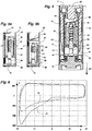
- the figure 1 has a telescopic damper comprising a cylindrical outer body 2 forming a tube, containing a piston 4 fixed to the end of a damper rod 20, sliding axially in this body with a seal to define a front chamber 6 and a rear chamber 22.
- the piston 4 comprises reduced passages of the fluid 8 between the front chamber 6 and the rear chamber 22, which slow down its movement as a function of the direction and the speed of passage of the fluid, and therefore the speed of the damper rod. 20.
- the piston 4 extends to the side conventionally called the front side, indicated by the arrow "AV", by a circular jacket 10 which fits towards the end of the stroke in an annular outer chamber 16, fitting around a end stop tube 12 forming a cylinder.
- the abutment tube 12 defining inside an inner chamber 26, is fixed by its front end to a cover 14 closing the front end of the outer body 2.
- the liner 10 comprises an outer annular boss 24 guiding it in the outer body 2, and a series of axially aligned radial bores 18 which, in the rear direction, have a smaller and smaller diameter.
- the fluid of this outer chamber is discharged to the inner chamber 26 by the holes 18 of calibrated section to achieve a braking of the advance of the rod of the damper 20.
- the fluid then passes from the inner chamber 26 to the volume rear 22 by reduced passages 8 of the piston 4.
- the holes 18 of the liner 10 are closed gradually which reduces more and more the total fluid passage section of the outer chamber 6 to the inner chamber 26, and increases the braking force that becomes very important near the end of the race.
- the figure 3 presents the force F of braking of the thrust bearing expressed in daN on the vertical axis, which is negative for braking, as a function of the stroke C expressed in millimeters, for different speeds of movement of the piston 4. For each speed we have a start of stroke of the attack stop at -25mm, then a race towards the negative values giving a braking force more and more important which comes from the progressive closure of the holes 18.
- the Figures 4, 5a and 5b have a thrust bearing comprising a plug 40 fitted inside the thrust tube 12, which has holes axial means 44 allowing free passage of the fluid on both sides forming the inner chamber 26.
- the plug 40 having an axial shape can be achieved economically by sintering metal powders.
- a helical thrust spring 46 is disposed between the piston 4 and the plug 40, to apply on this plug after a sufficient compression stroke of the telescopic damper, a forward force coming into contact.
- the plug 40 comprises an axial control chamber 48 containing a helical return spring 50, which bears downwards on a calibrated cylindrical pin 52 fitted in this chamber, which can slide axially.
- the force delivered by the return spring 50 is significantly lower than that delivered by the thrust spring 46.
- the calibrated pin 52 has a reduced clearance with the bore of the control chamber 48 receiving it, which is a fluid passage calibrated to form a hydraulic damper emptying at a slow speed depending on this game.
- the calibrated peg 52 a roller bearing roller, having both a high accuracy, a good surface and a very low cost.
- this calibrated pin 52 it is possible for this calibrated pin 52 to use a ball fitted into the bore.
- the return spring 50 is supported upwardly on a valve ball 54 closing an upper bore of this axial chamber opening on the top of the plug 40.
- This valve allows in particular a faster purge of the air contained in the chamber of control 48, escaping through the drilling of the top during assembly and first operations of the hydraulic damper.
- the base of the calibrated pin 52 is supported on a lower support 56, itself bearing on the front end cover 14 of the outer body.
- the lower support 56 can be produced economically by machining, by sintering metal powders, by molding a plastic material.
- the abutment tube 12 has an additional vacuum law lower bore 60, which is uncovered when the plug 40 is in a raised up position. figure 5a , and two additional upper law holes in charge 62, which are discovered when this bushel is in a lowered position presented figure 5b .
- the figure 6 presents the braking force F on the hydraulic stop as a function of the stroke C of this stop.
- the finish on the hydraulic stop is for a stroke C of 0mm.
- the attacking stop Upon arrival of the rod 20 towards the end of stroke, the attacking stop has a low stiffness presented by the first curve 70, ensuring comfort.
- the attacking abutment At the arrival of the rod 20 towards the end of the stroke, the attacking abutment has a high stiffness presented by the second curve 72.
- the second curve 72 has an increasing braking much more rapidly, which delivers at the end of stroke a much higher maximum force which is increased by 260daN.
- the stroke of the plug 40 downwards emptying the control chamber 48 is made after the application by the push spring 46 of a force for a minimum duration of several seconds, preferably more than three seconds, which can be d ' about five to ten seconds. In this case it is sufficiently far from the period given by the oscillation frequency of the suspension of a vehicle, which is about 1 Hz.
- the end stop may comprise only the additional bores 60, 62 on the abutment tube 12, or also in combination with the bores 18 on the sleeve 10, as shown. figure 1 .
- the telescopic damper comprising the hydraulic stop according to the invention can be arranged in the motor vehicle in all directions.
- the front side can be turned down or up, the body of the damper 2 can be attached to the suspension or the vehicle body.
Landscapes
- Engineering & Computer Science (AREA)
- General Engineering & Computer Science (AREA)
- Mechanical Engineering (AREA)
- Physics & Mathematics (AREA)
- Acoustics & Sound (AREA)
- Aviation & Aerospace Engineering (AREA)
- Fluid Mechanics (AREA)
- Fluid-Damping Devices (AREA)
- Vehicle Body Suspensions (AREA)
Applications Claiming Priority (1)
| Application Number | Priority Date | Filing Date | Title |
|---|---|---|---|
| FR1754603A FR3066796B1 (fr) | 2017-05-24 | 2017-05-24 | Butee hydraulique auto-ajustable pour la fin de course d’un mouvement oscillant |
Publications (2)
| Publication Number | Publication Date |
|---|---|
| EP3406931A1 true EP3406931A1 (de) | 2018-11-28 |
| EP3406931B1 EP3406931B1 (de) | 2020-04-01 |
Family
ID=59325501
Family Applications (1)
| Application Number | Title | Priority Date | Filing Date |
|---|---|---|---|
| EP18166928.4A Active EP3406931B1 (de) | 2017-05-24 | 2018-04-12 | Selbstregulierender hydraulischer anschlag für den endanschlag einer schwingungsbewegung |
Country Status (3)
| Country | Link |
|---|---|
| EP (1) | EP3406931B1 (de) |
| CN (1) | CN108930754B (de) |
| FR (1) | FR3066796B1 (de) |
Cited By (6)
| Publication number | Priority date | Publication date | Assignee | Title |
|---|---|---|---|---|
| IT201800010763A1 (it) * | 2018-12-03 | 2020-06-03 | Sistemi Sospensioni Spa | Ammortizzatore idraulico, particolarmente per sospensione di veicolo, con tampone idraulico operante durante la corsa di compressione dell'ammortizzatore e con dispositivo di regolazione per regolare il comportamento del tampone idraulico in funzione del carico del veicolo. |
| WO2020169893A1 (fr) * | 2019-02-21 | 2020-08-27 | Psa Automobiles Sa | Amortisseur hydraulique equipe d'une butee de fin de course auto-adaptable |
| FR3094057A1 (fr) * | 2019-03-22 | 2020-09-25 | Psa Automobiles Sa | Amortisseur avec butee de fin de course auto-adaptable equipee d’une chambre en avant d’un boisseau |
| FR3094058A1 (fr) * | 2019-03-22 | 2020-09-25 | Psa Automobiles Sa | Amortisseur avec butee de fin de course auto-adaptable equipee de perçages dans la tige |
| WO2021005180A1 (fr) * | 2019-07-09 | 2021-01-14 | Soben | Butée hydraulique pour amortisseur |
| ES2832888A1 (es) * | 2019-12-11 | 2021-06-11 | Kyb Europe Gmbh Sucursal En Navarra | Dispositivo de control hidraulico de carga variable |
Families Citing this family (3)
| Publication number | Priority date | Publication date | Assignee | Title |
|---|---|---|---|---|
| FR3094434B1 (fr) * | 2019-03-28 | 2021-11-19 | Psa Automobiles Sa | Amortisseur avec butee de fin de course equipee d’un clapet de limitation de pression |
| CN116292723A (zh) * | 2023-03-09 | 2023-06-23 | 四川宁江山川机械有限责任公司 | 一种用于车辆悬架减震器的阀体 |
| CN116518003B (zh) * | 2023-04-04 | 2025-10-03 | 四川宁江山川机械有限责任公司 | 一种用于车辆减振器液压缓冲机构的阀座 |
Citations (4)
| Publication number | Priority date | Publication date | Assignee | Title |
|---|---|---|---|---|
| GB311079A (en) * | 1928-04-27 | 1929-05-09 | Noel Banner Newton | Improvements in or relating to hydraulic and like shock absorbers |
| FR2902850A1 (fr) | 2006-06-21 | 2007-12-28 | Soben Soc Par Actions Simplifi | Dispositif a butee hydraulique, notamment pour amortisseur reglable |
| FR2973853A1 (fr) * | 2011-04-11 | 2012-10-12 | Peugeot Citroen Automobiles Sa | Amortisseur hydraulique en particulier pour vehicule automobile |
| FR3013413A1 (fr) * | 2013-11-16 | 2015-05-22 | Emc | Amortisseur hydraulique optimise contre les risques de talonnage |
Family Cites Families (4)
| Publication number | Priority date | Publication date | Assignee | Title |
|---|---|---|---|---|
| JPS5612428Y2 (de) * | 1977-12-13 | 1981-03-23 | ||
| DE102010020524A1 (de) * | 2010-05-14 | 2011-11-17 | Dr. Ing. H.C. F. Porsche Aktiengesellschaft | Restdruckhalteventil und Federbein |
| ES2561132B1 (es) * | 2014-07-23 | 2016-12-19 | Kyb Suspensions Europe, S.A. | Sistema de control de carga variable en un dispositivo hidráulico |
| DE102015100876B4 (de) * | 2014-12-16 | 2016-08-11 | medi prosthetics GmbH | Hydraulischer Dämpfungszylinder, insbesondere für ein Prothesenkniegelenk |
-
2017
- 2017-05-24 FR FR1754603A patent/FR3066796B1/fr not_active Expired - Fee Related
-
2018
- 2018-04-12 EP EP18166928.4A patent/EP3406931B1/de active Active
- 2018-05-24 CN CN201810507953.5A patent/CN108930754B/zh active Active
Patent Citations (4)
| Publication number | Priority date | Publication date | Assignee | Title |
|---|---|---|---|---|
| GB311079A (en) * | 1928-04-27 | 1929-05-09 | Noel Banner Newton | Improvements in or relating to hydraulic and like shock absorbers |
| FR2902850A1 (fr) | 2006-06-21 | 2007-12-28 | Soben Soc Par Actions Simplifi | Dispositif a butee hydraulique, notamment pour amortisseur reglable |
| FR2973853A1 (fr) * | 2011-04-11 | 2012-10-12 | Peugeot Citroen Automobiles Sa | Amortisseur hydraulique en particulier pour vehicule automobile |
| FR3013413A1 (fr) * | 2013-11-16 | 2015-05-22 | Emc | Amortisseur hydraulique optimise contre les risques de talonnage |
Cited By (18)
| Publication number | Priority date | Publication date | Assignee | Title |
|---|---|---|---|---|
| CN113195933A (zh) * | 2018-12-03 | 2021-07-30 | 马瑞利悬挂系统意大利公司 | 液压减震器,其具有在减震器的压缩行程期间操作的液压止动构件以及具有用于根据车辆负载来调节液压止动构件的性能的调节装置 |
| WO2020115642A1 (en) * | 2018-12-03 | 2020-06-11 | Sistemi Sospensioni S.P.A. | Hydraulic shock-absorber with a hydraulic stop member operating during the compression stroke of the shock-absorber and with an adjustment device for adjusting the behaviour of the hydraulic stop member depending on the vehicle load |
| IT201800010763A1 (it) * | 2018-12-03 | 2020-06-03 | Sistemi Sospensioni Spa | Ammortizzatore idraulico, particolarmente per sospensione di veicolo, con tampone idraulico operante durante la corsa di compressione dell'ammortizzatore e con dispositivo di regolazione per regolare il comportamento del tampone idraulico in funzione del carico del veicolo. |
| US11473645B2 (en) | 2018-12-03 | 2022-10-18 | Marelli Suspension Systems Italy S.P.A. | Hydraulic shock-absorber with hydraulic stop member and adjustment device |
| CN113195933B (zh) * | 2018-12-03 | 2022-08-09 | 马瑞利悬挂系统意大利公司 | 液压减震器 |
| WO2020169893A1 (fr) * | 2019-02-21 | 2020-08-27 | Psa Automobiles Sa | Amortisseur hydraulique equipe d'une butee de fin de course auto-adaptable |
| FR3093155A1 (fr) * | 2019-02-21 | 2020-08-28 | Psa Automobiles Sa | Amortisseur hydraulique equipe d’une butee de fin de course auto-adaptable |
| FR3094057A1 (fr) * | 2019-03-22 | 2020-09-25 | Psa Automobiles Sa | Amortisseur avec butee de fin de course auto-adaptable equipee d’une chambre en avant d’un boisseau |
| WO2020193882A1 (fr) * | 2019-03-22 | 2020-10-01 | Psa Automobiles Sa | Amortisseur avec butee de fin de course auto-adaptable equipee de perçages dans la tige |
| CN113614409A (zh) * | 2019-03-22 | 2021-11-05 | 标致雪铁龙汽车股份有限公司 | 带有于嵌套塞前配备腔室的自适应行程末尾止挡的减振器 |
| WO2020193884A1 (fr) * | 2019-03-22 | 2020-10-01 | Psa Automobiles Sa | Amortisseur avec butee de fin de course auto-adaptable equipee d'une chambre en avant d'un boisseau |
| FR3094058A1 (fr) * | 2019-03-22 | 2020-09-25 | Psa Automobiles Sa | Amortisseur avec butee de fin de course auto-adaptable equipee de perçages dans la tige |
| CN113614409B (zh) * | 2019-03-22 | 2023-09-15 | 标致雪铁龙汽车股份有限公司 | 带有于嵌套塞前配备腔室的自适应行程末尾止挡的减振器 |
| WO2021005180A1 (fr) * | 2019-07-09 | 2021-01-14 | Soben | Butée hydraulique pour amortisseur |
| FR3098561A1 (fr) * | 2019-07-09 | 2021-01-15 | Soben | Butée hydraulique pour amortisseur |
| ES2832888A1 (es) * | 2019-12-11 | 2021-06-11 | Kyb Europe Gmbh Sucursal En Navarra | Dispositivo de control hidraulico de carga variable |
| WO2021116510A1 (es) * | 2019-12-11 | 2021-06-17 | Kyb Europe Gmbh, Sucursal En Navarra | Dispositivo de control hidráulico de carga variable |
| EP4075014A4 (de) * | 2019-12-11 | 2023-02-22 | KYB Europe GmbH, Sucursal en Navarra | Hydraulische steuervorrichtung mit variabler last |
Also Published As
| Publication number | Publication date |
|---|---|
| EP3406931B1 (de) | 2020-04-01 |
| CN108930754A (zh) | 2018-12-04 |
| FR3066796A1 (fr) | 2018-11-30 |
| CN108930754B (zh) | 2021-11-02 |
| FR3066796B1 (fr) | 2019-06-21 |
Similar Documents
| Publication | Publication Date | Title |
|---|---|---|
| EP3406931B1 (de) | Selbstregulierender hydraulischer anschlag für den endanschlag einer schwingungsbewegung | |
| EP2199164B1 (de) | Dichtung für einen Hauptbremszylinder für ein Kraftfahrzeug | |
| EP3440375A1 (de) | Hydraulischer stossdämpfer mit einem anschlag mit verstellbarer bremsregelung | |
| EP4022196A1 (de) | Hydraulischer anschlag mit trägheitsmasse für kraftfahrzeugaufhängung | |
| FR2772858A1 (fr) | Boite de vitesses | |
| WO1991004876A1 (fr) | Procede de suspension de roue de vehicule | |
| FR2820478A1 (fr) | Butee hydraulique de traction pour amortisseurs de vibrations | |
| EP3717792B1 (de) | Hydraulischer stossdämpfer mit selbsteinstellbarem lastabhängigem endanschlag | |
| EP3918226B1 (de) | Hydraulischer anschlag für eine kraftfahrzeugaufhängung mit trägheitsmasse | |
| FR2766129A1 (fr) | Unite a piston-cylindre pour une suspension de roue d'un vehicule | |
| EP3004683A1 (de) | Stossdämpfer mit hydraulischer endlagendämpfung | |
| FR2784165A1 (fr) | Soupape avec dispositif d'amortissement | |
| EP3948011B1 (de) | Fluiddämpfer aufweisend einen selbstanpassenden anschlag mit einem schwimmenden schieber | |
| EP3861229B1 (de) | Hydraulischer stossdämpfer mit hydraulischer endanschlagsbegrenzung an einer selbst einstellbaren höhe | |
| EP1774195A2 (de) | Dämpfungsvorrichtung mit hilfskraftunterstützter verzögerung sowie deren anwendung zur dämpfung der zusammenschiebbaren lenksäule eines kraftfahrzeugs | |
| EP3948012A1 (de) | Dämpfer mit wegbegrenzungsanschlag mit einem druckbegrenzungsventil | |
| FR3086359A1 (fr) | Amortisseur hydraulique avec butee hydraulique de fin de course a positionnement auto-ajustable | |
| FR2974609A1 (fr) | Amortisseur hydraulique comprenant une tige coulissant dans un tube | |
| EP3942196B1 (de) | Fluiddämpfer auweisend einen selbstanpassenden anschlag mit einer kammer vor einem schieber | |
| WO2020169893A1 (fr) | Amortisseur hydraulique equipe d'une butee de fin de course auto-adaptable | |
| FR2876757A1 (fr) | Verin, de preference double effet, a amortisseur de fin de course | |
| EP3942195B1 (de) | Fluiddämpfer aufweisend einen selbstanpanssenden anschlag mit öffnungen an der stange | |
| CA2563794A1 (fr) | Systeme amortisseur a detente rapide et butee hydraulique de fin de course et procede d'utilisation | |
| EP1557584B1 (de) | Komprimierte Gasfeder mit in einem maximalen und einen Zwischenbereich einstellbaren Hubweg | |
| FR2487031A1 (fr) | Perfectionnement aux amortisseurs hydrauliques telescopiques, notamment pour suspensions de vehicules automobiles |
Legal Events
| Date | Code | Title | Description |
|---|---|---|---|
| PUAI | Public reference made under article 153(3) epc to a published international application that has entered the european phase |
Free format text: ORIGINAL CODE: 0009012 |
|
| STAA | Information on the status of an ep patent application or granted ep patent |
Free format text: STATUS: THE APPLICATION HAS BEEN PUBLISHED |
|
| AK | Designated contracting states |
Kind code of ref document: A1 Designated state(s): AL AT BE BG CH CY CZ DE DK EE ES FI FR GB GR HR HU IE IS IT LI LT LU LV MC MK MT NL NO PL PT RO RS SE SI SK SM TR |
|
| AX | Request for extension of the european patent |
Extension state: BA ME |
|
| STAA | Information on the status of an ep patent application or granted ep patent |
Free format text: STATUS: REQUEST FOR EXAMINATION WAS MADE |
|
| 17P | Request for examination filed |
Effective date: 20190516 |
|
| RBV | Designated contracting states (corrected) |
Designated state(s): AL AT BE BG CH CY CZ DE DK EE ES FI FR GB GR HR HU IE IS IT LI LT LU LV MC MK MT NL NO PL PT RO RS SE SI SK SM TR |
|
| RIC1 | Information provided on ipc code assigned before grant |
Ipc: F16F 9/346 20060101ALN20190919BHEP Ipc: F16F 9/516 20060101ALI20190919BHEP Ipc: F16F 9/512 20060101ALI20190919BHEP Ipc: F16F 9/49 20060101AFI20190919BHEP |
|
| GRAP | Despatch of communication of intention to grant a patent |
Free format text: ORIGINAL CODE: EPIDOSNIGR1 |
|
| STAA | Information on the status of an ep patent application or granted ep patent |
Free format text: STATUS: GRANT OF PATENT IS INTENDED |
|
| RIC1 | Information provided on ipc code assigned before grant |
Ipc: F16F 9/516 20060101ALI20190920BHEP Ipc: F16F 9/512 20060101ALI20190920BHEP Ipc: F16F 9/346 20060101ALN20190920BHEP Ipc: F16F 9/49 20060101AFI20190920BHEP |
|
| INTG | Intention to grant announced |
Effective date: 20191030 |
|
| GRAS | Grant fee paid |
Free format text: ORIGINAL CODE: EPIDOSNIGR3 |
|
| GRAA | (expected) grant |
Free format text: ORIGINAL CODE: 0009210 |
|
| STAA | Information on the status of an ep patent application or granted ep patent |
Free format text: STATUS: THE PATENT HAS BEEN GRANTED |
|
| AK | Designated contracting states |
Kind code of ref document: B1 Designated state(s): AL AT BE BG CH CY CZ DE DK EE ES FI FR GB GR HR HU IE IS IT LI LT LU LV MC MK MT NL NO PL PT RO RS SE SI SK SM TR |
|
| REG | Reference to a national code |
Ref country code: GB Ref legal event code: FG4D Free format text: NOT ENGLISH |
|
| REG | Reference to a national code |
Ref country code: CH Ref legal event code: EP Ref country code: AT Ref legal event code: REF Ref document number: 1251737 Country of ref document: AT Kind code of ref document: T Effective date: 20200415 |
|
| REG | Reference to a national code |
Ref country code: DE Ref legal event code: R096 Ref document number: 602018003358 Country of ref document: DE |
|
| REG | Reference to a national code |
Ref country code: IE Ref legal event code: FG4D Free format text: LANGUAGE OF EP DOCUMENT: FRENCH |
|
| PG25 | Lapsed in a contracting state [announced via postgrant information from national office to epo] |
Ref country code: BG Free format text: LAPSE BECAUSE OF FAILURE TO SUBMIT A TRANSLATION OF THE DESCRIPTION OR TO PAY THE FEE WITHIN THE PRESCRIBED TIME-LIMIT Effective date: 20200701 |
|
| REG | Reference to a national code |
Ref country code: NL Ref legal event code: MP Effective date: 20200401 |
|
| REG | Reference to a national code |
Ref country code: LT Ref legal event code: MG4D Ref country code: DE Ref legal event code: R084 Ref document number: 602018003358 Country of ref document: DE |
|
| PG25 | Lapsed in a contracting state [announced via postgrant information from national office to epo] |
Ref country code: FI Free format text: LAPSE BECAUSE OF FAILURE TO SUBMIT A TRANSLATION OF THE DESCRIPTION OR TO PAY THE FEE WITHIN THE PRESCRIBED TIME-LIMIT Effective date: 20200401 Ref country code: GR Free format text: LAPSE BECAUSE OF FAILURE TO SUBMIT A TRANSLATION OF THE DESCRIPTION OR TO PAY THE FEE WITHIN THE PRESCRIBED TIME-LIMIT Effective date: 20200702 Ref country code: NO Free format text: LAPSE BECAUSE OF FAILURE TO SUBMIT A TRANSLATION OF THE DESCRIPTION OR TO PAY THE FEE WITHIN THE PRESCRIBED TIME-LIMIT Effective date: 20200701 Ref country code: PT Free format text: LAPSE BECAUSE OF FAILURE TO SUBMIT A TRANSLATION OF THE DESCRIPTION OR TO PAY THE FEE WITHIN THE PRESCRIBED TIME-LIMIT Effective date: 20200817 Ref country code: CZ Free format text: LAPSE BECAUSE OF FAILURE TO SUBMIT A TRANSLATION OF THE DESCRIPTION OR TO PAY THE FEE WITHIN THE PRESCRIBED TIME-LIMIT Effective date: 20200401 Ref country code: LT Free format text: LAPSE BECAUSE OF FAILURE TO SUBMIT A TRANSLATION OF THE DESCRIPTION OR TO PAY THE FEE WITHIN THE PRESCRIBED TIME-LIMIT Effective date: 20200401 Ref country code: IS Free format text: LAPSE BECAUSE OF FAILURE TO SUBMIT A TRANSLATION OF THE DESCRIPTION OR TO PAY THE FEE WITHIN THE PRESCRIBED TIME-LIMIT Effective date: 20200801 Ref country code: SE Free format text: LAPSE BECAUSE OF FAILURE TO SUBMIT A TRANSLATION OF THE DESCRIPTION OR TO PAY THE FEE WITHIN THE PRESCRIBED TIME-LIMIT Effective date: 20200401 Ref country code: NL Free format text: LAPSE BECAUSE OF FAILURE TO SUBMIT A TRANSLATION OF THE DESCRIPTION OR TO PAY THE FEE WITHIN THE PRESCRIBED TIME-LIMIT Effective date: 20200401 |
|
| RAP2 | Party data changed (patent owner data changed or rights of a patent transferred) |
Owner name: PSA AUTOMOBILES SA |
|
| REG | Reference to a national code |
Ref country code: AT Ref legal event code: MK05 Ref document number: 1251737 Country of ref document: AT Kind code of ref document: T Effective date: 20200401 |
|
| PG25 | Lapsed in a contracting state [announced via postgrant information from national office to epo] |
Ref country code: LV Free format text: LAPSE BECAUSE OF FAILURE TO SUBMIT A TRANSLATION OF THE DESCRIPTION OR TO PAY THE FEE WITHIN THE PRESCRIBED TIME-LIMIT Effective date: 20200401 Ref country code: HR Free format text: LAPSE BECAUSE OF FAILURE TO SUBMIT A TRANSLATION OF THE DESCRIPTION OR TO PAY THE FEE WITHIN THE PRESCRIBED TIME-LIMIT Effective date: 20200401 Ref country code: RS Free format text: LAPSE BECAUSE OF FAILURE TO SUBMIT A TRANSLATION OF THE DESCRIPTION OR TO PAY THE FEE WITHIN THE PRESCRIBED TIME-LIMIT Effective date: 20200401 |
|
| PG25 | Lapsed in a contracting state [announced via postgrant information from national office to epo] |
Ref country code: AL Free format text: LAPSE BECAUSE OF FAILURE TO SUBMIT A TRANSLATION OF THE DESCRIPTION OR TO PAY THE FEE WITHIN THE PRESCRIBED TIME-LIMIT Effective date: 20200401 |
|
| REG | Reference to a national code |
Ref country code: DE Ref legal event code: R097 Ref document number: 602018003358 Country of ref document: DE |
|
| PG25 | Lapsed in a contracting state [announced via postgrant information from national office to epo] |
Ref country code: MC Free format text: LAPSE BECAUSE OF FAILURE TO SUBMIT A TRANSLATION OF THE DESCRIPTION OR TO PAY THE FEE WITHIN THE PRESCRIBED TIME-LIMIT Effective date: 20200401 Ref country code: ES Free format text: LAPSE BECAUSE OF FAILURE TO SUBMIT A TRANSLATION OF THE DESCRIPTION OR TO PAY THE FEE WITHIN THE PRESCRIBED TIME-LIMIT Effective date: 20200401 Ref country code: RO Free format text: LAPSE BECAUSE OF FAILURE TO SUBMIT A TRANSLATION OF THE DESCRIPTION OR TO PAY THE FEE WITHIN THE PRESCRIBED TIME-LIMIT Effective date: 20200401 Ref country code: DK Free format text: LAPSE BECAUSE OF FAILURE TO SUBMIT A TRANSLATION OF THE DESCRIPTION OR TO PAY THE FEE WITHIN THE PRESCRIBED TIME-LIMIT Effective date: 20200401 Ref country code: IT Free format text: LAPSE BECAUSE OF FAILURE TO SUBMIT A TRANSLATION OF THE DESCRIPTION OR TO PAY THE FEE WITHIN THE PRESCRIBED TIME-LIMIT Effective date: 20200401 Ref country code: SM Free format text: LAPSE BECAUSE OF FAILURE TO SUBMIT A TRANSLATION OF THE DESCRIPTION OR TO PAY THE FEE WITHIN THE PRESCRIBED TIME-LIMIT Effective date: 20200401 Ref country code: AT Free format text: LAPSE BECAUSE OF FAILURE TO SUBMIT A TRANSLATION OF THE DESCRIPTION OR TO PAY THE FEE WITHIN THE PRESCRIBED TIME-LIMIT Effective date: 20200401 Ref country code: EE Free format text: LAPSE BECAUSE OF FAILURE TO SUBMIT A TRANSLATION OF THE DESCRIPTION OR TO PAY THE FEE WITHIN THE PRESCRIBED TIME-LIMIT Effective date: 20200401 Ref country code: LU Free format text: LAPSE BECAUSE OF NON-PAYMENT OF DUE FEES Effective date: 20200412 |
|
| REG | Reference to a national code |
Ref country code: BE Ref legal event code: MM Effective date: 20200430 |
|
| PLBE | No opposition filed within time limit |
Free format text: ORIGINAL CODE: 0009261 |
|
| STAA | Information on the status of an ep patent application or granted ep patent |
Free format text: STATUS: NO OPPOSITION FILED WITHIN TIME LIMIT |
|
| PG25 | Lapsed in a contracting state [announced via postgrant information from national office to epo] |
Ref country code: PL Free format text: LAPSE BECAUSE OF FAILURE TO SUBMIT A TRANSLATION OF THE DESCRIPTION OR TO PAY THE FEE WITHIN THE PRESCRIBED TIME-LIMIT Effective date: 20200401 Ref country code: BE Free format text: LAPSE BECAUSE OF NON-PAYMENT OF DUE FEES Effective date: 20200430 Ref country code: SK Free format text: LAPSE BECAUSE OF FAILURE TO SUBMIT A TRANSLATION OF THE DESCRIPTION OR TO PAY THE FEE WITHIN THE PRESCRIBED TIME-LIMIT Effective date: 20200401 |
|
| 26N | No opposition filed |
Effective date: 20210112 |
|
| REG | Reference to a national code |
Ref country code: GB Ref legal event code: 746 Effective date: 20210302 |
|
| PG25 | Lapsed in a contracting state [announced via postgrant information from national office to epo] |
Ref country code: IE Free format text: LAPSE BECAUSE OF NON-PAYMENT OF DUE FEES Effective date: 20200412 |
|
| PG25 | Lapsed in a contracting state [announced via postgrant information from national office to epo] |
Ref country code: SI Free format text: LAPSE BECAUSE OF FAILURE TO SUBMIT A TRANSLATION OF THE DESCRIPTION OR TO PAY THE FEE WITHIN THE PRESCRIBED TIME-LIMIT Effective date: 20200401 |
|
| PG25 | Lapsed in a contracting state [announced via postgrant information from national office to epo] |
Ref country code: LI Free format text: LAPSE BECAUSE OF NON-PAYMENT OF DUE FEES Effective date: 20210430 Ref country code: CH Free format text: LAPSE BECAUSE OF NON-PAYMENT OF DUE FEES Effective date: 20210430 |
|
| PG25 | Lapsed in a contracting state [announced via postgrant information from national office to epo] |
Ref country code: TR Free format text: LAPSE BECAUSE OF FAILURE TO SUBMIT A TRANSLATION OF THE DESCRIPTION OR TO PAY THE FEE WITHIN THE PRESCRIBED TIME-LIMIT Effective date: 20200401 Ref country code: MT Free format text: LAPSE BECAUSE OF FAILURE TO SUBMIT A TRANSLATION OF THE DESCRIPTION OR TO PAY THE FEE WITHIN THE PRESCRIBED TIME-LIMIT Effective date: 20200401 Ref country code: CY Free format text: LAPSE BECAUSE OF FAILURE TO SUBMIT A TRANSLATION OF THE DESCRIPTION OR TO PAY THE FEE WITHIN THE PRESCRIBED TIME-LIMIT Effective date: 20200401 |
|
| PG25 | Lapsed in a contracting state [announced via postgrant information from national office to epo] |
Ref country code: MK Free format text: LAPSE BECAUSE OF FAILURE TO SUBMIT A TRANSLATION OF THE DESCRIPTION OR TO PAY THE FEE WITHIN THE PRESCRIBED TIME-LIMIT Effective date: 20200401 |
|
| REG | Reference to a national code |
Ref country code: DE Ref legal event code: R081 Ref document number: 602018003358 Country of ref document: DE Owner name: STELLANTIS AUTO SAS, FR Free format text: FORMER OWNER: PSA AUTOMOBILES SA, POISSY, FR |
|
| PGFP | Annual fee paid to national office [announced via postgrant information from national office to epo] |
Ref country code: DE Payment date: 20250319 Year of fee payment: 8 |
|
| PGFP | Annual fee paid to national office [announced via postgrant information from national office to epo] |
Ref country code: GB Payment date: 20260319 Year of fee payment: 9 |
|
| PGFP | Annual fee paid to national office [announced via postgrant information from national office to epo] |
Ref country code: FR Payment date: 20260319 Year of fee payment: 9 |