EP3407431B1 - Kompaktstecker - Google Patents
Kompaktstecker Download PDFInfo
- Publication number
- EP3407431B1 EP3407431B1 EP18173290.0A EP18173290A EP3407431B1 EP 3407431 B1 EP3407431 B1 EP 3407431B1 EP 18173290 A EP18173290 A EP 18173290A EP 3407431 B1 EP3407431 B1 EP 3407431B1
- Authority
- EP
- European Patent Office
- Prior art keywords
- housing
- sleeve
- strand
- contact
- fastener unit
- Prior art date
- Legal status (The legal status is an assumption and is not a legal conclusion. Google has not performed a legal analysis and makes no representation as to the accuracy of the status listed.)
- Active
Links
Images


Classifications
-
- H—ELECTRICITY
- H01—ELECTRIC ELEMENTS
- H01R—ELECTRICALLY-CONDUCTIVE CONNECTIONS; STRUCTURAL ASSOCIATIONS OF A PLURALITY OF MUTUALLY-INSULATED ELECTRICAL CONNECTING ELEMENTS; COUPLING DEVICES; CURRENT COLLECTORS
- H01R13/00—Details of coupling devices of the kinds covered by groups H01R12/70 or H01R24/00 - H01R33/00
- H01R13/40—Securing contact members in or to a base or case; Insulating of contact members
- H01R13/42—Securing in a demountable manner
- H01R13/428—Securing in a demountable manner by resilient locking means on the contact members; by locking means on resilient contact members
- H01R13/434—Securing in a demountable manner by resilient locking means on the contact members; by locking means on resilient contact members by separate resilient locking means on contact member, e.g. retainer collar or ring around contact member
-
- H—ELECTRICITY
- H01—ELECTRIC ELEMENTS
- H01R—ELECTRICALLY-CONDUCTIVE CONNECTIONS; STRUCTURAL ASSOCIATIONS OF A PLURALITY OF MUTUALLY-INSULATED ELECTRICAL CONNECTING ELEMENTS; COUPLING DEVICES; CURRENT COLLECTORS
- H01R13/00—Details of coupling devices of the kinds covered by groups H01R12/70 or H01R24/00 - H01R33/00
- H01R13/46—Bases; Cases
- H01R13/502—Bases; Cases composed of different pieces
-
- G—PHYSICS
- G02—OPTICS
- G02B—OPTICAL ELEMENTS, SYSTEMS OR APPARATUS
- G02B6/00—Light guides; Structural details of arrangements comprising light guides and other optical elements, e.g. couplings
- G02B6/24—Coupling light guides
- G02B6/36—Mechanical coupling means
- G02B6/38—Mechanical coupling means having fibre to fibre mating means
- G02B6/3807—Dismountable connectors, i.e. comprising plugs
- G02B6/381—Dismountable connectors, i.e. comprising plugs of the ferrule type, e.g. fibre ends embedded in ferrules, connecting a pair of fibres
- G02B6/3825—Dismountable connectors, i.e. comprising plugs of the ferrule type, e.g. fibre ends embedded in ferrules, connecting a pair of fibres with an intermediate part, e.g. adapter, receptacle, linking two plugs
-
- G—PHYSICS
- G02—OPTICS
- G02B—OPTICAL ELEMENTS, SYSTEMS OR APPARATUS
- G02B6/00—Light guides; Structural details of arrangements comprising light guides and other optical elements, e.g. couplings
- G02B6/24—Coupling light guides
- G02B6/36—Mechanical coupling means
- G02B6/38—Mechanical coupling means having fibre to fibre mating means
- G02B6/3807—Dismountable connectors, i.e. comprising plugs
- G02B6/3873—Connectors using guide surfaces for aligning ferrule ends, e.g. tubes, sleeves, V-grooves, rods, pins, balls
- G02B6/3874—Connectors using guide surfaces for aligning ferrule ends, e.g. tubes, sleeves, V-grooves, rods, pins, balls using tubes, sleeves to align ferrules
- G02B6/3878—Connectors using guide surfaces for aligning ferrule ends, e.g. tubes, sleeves, V-grooves, rods, pins, balls using tubes, sleeves to align ferrules comprising a plurality of ferrules, branching and break-out means
-
- G—PHYSICS
- G02—OPTICS
- G02B—OPTICAL ELEMENTS, SYSTEMS OR APPARATUS
- G02B6/00—Light guides; Structural details of arrangements comprising light guides and other optical elements, e.g. couplings
- G02B6/24—Coupling light guides
- G02B6/36—Mechanical coupling means
- G02B6/38—Mechanical coupling means having fibre to fibre mating means
- G02B6/3807—Dismountable connectors, i.e. comprising plugs
- G02B6/389—Dismountable connectors, i.e. comprising plugs characterised by the method of fastening connecting plugs and sockets, e.g. screw- or nut-lock, snap-in, bayonet type
- G02B6/3891—Bayonet type
-
- H—ELECTRICITY
- H01—ELECTRIC ELEMENTS
- H01R—ELECTRICALLY-CONDUCTIVE CONNECTIONS; STRUCTURAL ASSOCIATIONS OF A PLURALITY OF MUTUALLY-INSULATED ELECTRICAL CONNECTING ELEMENTS; COUPLING DEVICES; CURRENT COLLECTORS
- H01R13/00—Details of coupling devices of the kinds covered by groups H01R12/70 or H01R24/00 - H01R33/00
- H01R13/40—Securing contact members in or to a base or case; Insulating of contact members
- H01R13/42—Securing in a demountable manner
- H01R13/422—Securing in resilient one-piece base or case, e.g. by friction; One-piece base or case formed with resilient locking means
-
- H—ELECTRICITY
- H01—ELECTRIC ELEMENTS
- H01R—ELECTRICALLY-CONDUCTIVE CONNECTIONS; STRUCTURAL ASSOCIATIONS OF A PLURALITY OF MUTUALLY-INSULATED ELECTRICAL CONNECTING ELEMENTS; COUPLING DEVICES; CURRENT COLLECTORS
- H01R13/00—Details of coupling devices of the kinds covered by groups H01R12/70 or H01R24/00 - H01R33/00
- H01R13/40—Securing contact members in or to a base or case; Insulating of contact members
- H01R13/42—Securing in a demountable manner
- H01R13/426—Securing by a separate resilient retaining piece supported by base or case, e.g. collar or metal contact-retention clip
-
- H—ELECTRICITY
- H01—ELECTRIC ELEMENTS
- H01R—ELECTRICALLY-CONDUCTIVE CONNECTIONS; STRUCTURAL ASSOCIATIONS OF A PLURALITY OF MUTUALLY-INSULATED ELECTRICAL CONNECTING ELEMENTS; COUPLING DEVICES; CURRENT COLLECTORS
- H01R13/00—Details of coupling devices of the kinds covered by groups H01R12/70 or H01R24/00 - H01R33/00
- H01R13/62—Means for facilitating engagement or disengagement of coupling parts or for holding them in engagement
- H01R13/627—Snap or like fastening
-
- H—ELECTRICITY
- H01—ELECTRIC ELEMENTS
- H01R—ELECTRICALLY-CONDUCTIVE CONNECTIONS; STRUCTURAL ASSOCIATIONS OF A PLURALITY OF MUTUALLY-INSULATED ELECTRICAL CONNECTING ELEMENTS; COUPLING DEVICES; CURRENT COLLECTORS
- H01R13/00—Details of coupling devices of the kinds covered by groups H01R12/70 or H01R24/00 - H01R33/00
- H01R13/62—Means for facilitating engagement or disengagement of coupling parts or for holding them in engagement
- H01R13/629—Additional means for facilitating engagement or disengagement of coupling parts, e.g. aligning or guiding means, levers, gas pressure electrical locking indicators, manufacturing tolerances
-
- G—PHYSICS
- G02—OPTICS
- G02B—OPTICAL ELEMENTS, SYSTEMS OR APPARATUS
- G02B6/00—Light guides; Structural details of arrangements comprising light guides and other optical elements, e.g. couplings
- G02B6/24—Coupling light guides
- G02B6/36—Mechanical coupling means
- G02B6/38—Mechanical coupling means having fibre to fibre mating means
- G02B6/3807—Dismountable connectors, i.e. comprising plugs
- G02B6/381—Dismountable connectors, i.e. comprising plugs of the ferrule type, e.g. fibre ends embedded in ferrules, connecting a pair of fibres
- G02B6/3818—Dismountable connectors, i.e. comprising plugs of the ferrule type, e.g. fibre ends embedded in ferrules, connecting a pair of fibres of a low-reflection-loss type
- G02B6/3821—Dismountable connectors, i.e. comprising plugs of the ferrule type, e.g. fibre ends embedded in ferrules, connecting a pair of fibres of a low-reflection-loss type with axial spring biasing or loading means
-
- H—ELECTRICITY
- H01—ELECTRIC ELEMENTS
- H01R—ELECTRICALLY-CONDUCTIVE CONNECTIONS; STRUCTURAL ASSOCIATIONS OF A PLURALITY OF MUTUALLY-INSULATED ELECTRICAL CONNECTING ELEMENTS; COUPLING DEVICES; CURRENT COLLECTORS
- H01R13/00—Details of coupling devices of the kinds covered by groups H01R12/70 or H01R24/00 - H01R33/00
- H01R13/62—Means for facilitating engagement or disengagement of coupling parts or for holding them in engagement
- H01R13/621—Bolt, set screw or screw clamp
- H01R13/6215—Bolt, set screw or screw clamp using one or more bolts
-
- H—ELECTRICITY
- H01—ELECTRIC ELEMENTS
- H01R—ELECTRICALLY-CONDUCTIVE CONNECTIONS; STRUCTURAL ASSOCIATIONS OF A PLURALITY OF MUTUALLY-INSULATED ELECTRICAL CONNECTING ELEMENTS; COUPLING DEVICES; CURRENT COLLECTORS
- H01R13/00—Details of coupling devices of the kinds covered by groups H01R12/70 or H01R24/00 - H01R33/00
- H01R13/62—Means for facilitating engagement or disengagement of coupling parts or for holding them in engagement
- H01R13/625—Casing or ring with bayonet engagement
-
- H—ELECTRICITY
- H01—ELECTRIC ELEMENTS
- H01R—ELECTRICALLY-CONDUCTIVE CONNECTIONS; STRUCTURAL ASSOCIATIONS OF A PLURALITY OF MUTUALLY-INSULATED ELECTRICAL CONNECTING ELEMENTS; COUPLING DEVICES; CURRENT COLLECTORS
- H01R2107/00—Four or more poles
Definitions
- the invention relates to a connector for connecting at least two cables to at least two corresponding cables.
- Each cable can here include one or more electrical conductors, and / or one or more light conductors, that is to say one or more optical fibers.
- the connector constitutes a first connector which is configured to be itself fixed to a second connector. Said at least two cables are attached to said first connector and said at least two corresponding cables are attached to the second connector. Also, when the first and the second connector are assembled together, said at least two cables are connected together with said at least two corresponding cables.
- the document DE 10 2013 209533 A1 in fact reveals a connector comprising a housing, and a cable fixing assembly, in which the housing has an internal housing opening out through an opening in a rear face of the housing; the cable fixing assembly has an axis, and comprises a contact and a sleeve, said contact being configured to be fixed to one end of a cable previously passed through the sleeve; the connector has, for the cable fixing assembly, a bayonet connection enabling the cable fixing assembly to be mounted at least in part in the internal housing of the housing; and the housing and the cable fixing assembly are configured such that, upon said mounting, the cable fixing assembly is inserted through said opening into the housing.
- a connector comprising a housing, and several cable fixing assemblies.
- the different cable tie sets are all the same.
- Each cable tie assembly is used to secure one of the cables to the enclosure. All cables are attached to the housing via the rear face thereof.
- the box has openings in its rear face, namely as many openings as there are cables to be fixed.
- Each cable tie assembly includes a contact, a spring, and a sleeve.
- the contact is an end part (or a set of parts), attached to the end of the cable to ensure connection with a corresponding contact of another fixing assembly with which the fixing assembly in question is to be connected.
- the function of the contact is defined in connection with the corresponding contact of the second connector: the contact is a terminating part (or a set of parts), which is able, by cooperating with the corresponding contact of the second connector, to establish the connection between the electrical conductor (s) or of cable light and the corresponding electrical or light conductor (s) of the cable attached to the second connector.
- each contact is configured to be attached to one end of one of the cables previously passed through the sleeve, and then to be mounted in an insertion direction by passing through one of the openings in the rear face of the housing.
- the direction of insertion is the same for all cable tie assemblies.
- Connectors of this type perform the connection function very satisfactorily; however, they are not very compact, which can be problematic for some applications.
- the objective of the invention is to provide a connector (a 'first connector') to which a number of cables can be attached so as to be connected to the same number of corresponding cables by means of a second connector, and which has increased compactness compared to the connector indicated above.
- the first and second cable fixing assemblies are placed at least in part in the same housing.
- the expression 'in the same housing' means here that the parts of the housing in which the parts of the first and of the second contact fastening assembly which are in the housing are disposed communicate, that is to say are not entirely separated from each other by a partition. Therefore, in the mounted position in the housing, the parts of the first and second contact fastening assemblies which are in the housing are at least partly opposite each other.
- the portions of the first and of the second cable fixing assembly closest to one another are located directly opposite one another.
- the first and second cable tie assemblies can be placed extremely close to each other. Thanks to these arrangements, the housing of the connector can be reduced in size, the center distance between the cable fixing assemblies can be small, and the connector can be compact.
- the connector defined above comprises at least two cable fixing assemblies and can naturally include any number strictly greater than two.
- the contact has the same function as the connector contact presented previously in the 'Background to the invention' section.
- Each cable can be a cable comprising one or more electrical conductors and / or one or more optical fibers. Consequently, each contact can be a contact provided for one or more electrical conductors and / or one or more optical fibers.
- the internal housing naturally also has at least one other opening for the connection of the contacts of the fixing assemblies, normally towards the front.
- the housing can be made in one or more parts.
- the housing of the fixing assemblies can be made of a conductive material, for example metal; the housing may for example be constituted by a single metal part, in particular machined. This may be the case, for example, if the contacts have an insulating outer sheath.
- the housing is preferably formed of an electrically insulating material, for example of plastic (polymer or other).
- the housing can then for example be formed by an insulating insert placed inside a metallic outer shell. If not, it can optionally be entirely made of plastic.
- a bayonet connection is a specific arrangement or configuration of two parts making it possible to assemble them by carrying out two movements, namely a relative translational movement of one part with respect to the other followed by a relative rotational movement of 'one piece in relation to the other.
- a bayonet connection can also be referred to as a 'quarter turn' connection.
- the term 'quarter turn' in no way implies here that the rotation is equal to a quarter turn.
- the rotation can be between 20 and 45 °, for example.
- each of said first and second cable fixing assembly is configured to be mounted by inserting the cable fixing assembly axially into the opening of the housing up to a certain point. predetermined axial position, then rotating the sleeve around the axis of the fastener assembly.
- the purpose and effect of mounting the fastening assembly at least in part in the internal housing of the housing is to secure the fastening assembly to the housing.
- additional means can be provided to ensure that the fixing assembly remains durably in the desired mounting position and does not come apart over time.
- the connector comprises, for at least one of said first and second cable fixing assembly, a latching mechanism (or clipping) allowing the cable fixing assembly, after assembly, to be locked in the mounted position, and thus to be kept in a fixed position relative to the housing.
- Snap-fastening is a method of assembling two parts by engagement and elastic deformation (generally local deformation, for example of a tongue, or by deformation of all the parts involved in the assembly). When the two parts are engaged in the snap-in position, the parts have generally returned to their initial shape and no longer exhibit elastic deformation (or less elastic deformation). When the two parts are engaged with each other in the latching position, they cooperate with each other so as to oppose, or even block, the relative movements of said parts in the direction of release ( opposite to the sense of engagement).
- each of the first and second cable attachment assemblies is configured to be mounted in the housing by inserting the cable attachment assembly into the opening of the housing to a first axial position, then by rotating the sleeve around the axis of the fixing assembly, then by releasing the sleeve, the cable fixing assembly then locking axially with respect to the housing under the action of return means.
- return means can for example be a spring.
- the housing and the sleeve can be arranged in different ways to secure the attachment of the cable fixing assembly to the housing.
- first holding means to ensure the locking of all the degrees of freedom of the sleeve (relative to the housing) except a translation relative to the axis of the fixing assembly and a rotation around this axis
- second and third holding means to ensure the locking of the sleeve respectively in translation in the direction of insertion and in rotation around this axis.
- the fixing of the cable is ensured largely by the guide surface (s). These surfaces make it possible to block (however possibly with a certain tolerance, a certain play) all the degrees of freedom of the sleeve except the translation with respect to the axis of the fixing assembly and a rotation about this axis. Most often, the sleeve is of cylindrical outer shape.
- the guide surface (s) also have a cylindrical shape, with a diameter at least equal to that of the sleeve, which makes it possible to ensure that the sleeve is arranged coaxially with the guide surfaces and thus to ensure that the sleeve is held in position (apart from its axial translation and its rotation with respect to the axis of the fixing assembly) .
- the peculiarity of the connector according to the invention is that, unlike the connector presented previously, at least for the two cable fixing assemblies, the contacts are configured to be mounted in the direction of insertion by passing through the same opening of the cable. rear side of the housing.
- said at least a guide surface of the cable fixing assembly in question extends only over a part of the periphery of the sleeve, and leaves portions of the sleeves of the first and of the second cable fixing assembly closest to one of the other directly opposite one another, these portions of the sleeves of the first and of the second cable fixing assembly not being separated from each other by any partition of the housing.
- This arrangement makes it possible to position the contacts of the first and of the second cable fixing assembly, within the housing of the housing, very close to one another. Thanks to this arrangement, the center distance between the two fixing assemblies, in the mounted position, can be reduced to a minimum; in particular, the sleeves of the two fixing assemblies in the mounted position may be separated only by a very small distance; it is not necessary to provide a minimum distance, as would be the case if a wall of the housing were to separate the two sleeves from each other.
- the center distance between the first and the second cable fixing assembly can therefore be less than 1.5 times or even 1.2 times the external diameter of the sleeve (this external diameter relates to the part of the sleeve which is located in the housing in the mounted position, and which cooperates with the guide surface (s).
- the sleeve may include a part located outside the housing in the mounted position; this part may be of any shape, in particular of non-cylindrical shape).
- said at least one guide surface extends (possibly extends only) over two angular sectors opposite to each other.
- these two angular sectors are oriented in directions which are generally perpendicular or oblique with respect to the line passing through the axes. of the first and second cable fixing assembly.
- the connector comprises three fixing assemblies of cable, and when these three cable tie assemblies are placed right next to each other in the mounted position (aligned).
- the box For the cable fixing assembly placed between the other two (in the mounted position), the box then has exactly two guide surfaces located opposite one another and between which the sleeve is located, in the mounted position.
- the connector can be arranged in different ways.
- the second retaining means may in particular include a spring, which forms a latching mechanism.
- the fixing of the cable fixing assembly is then ensured by the cooperation of the housing, the spring and the contact with the sleeve.
- the spring is generally of the helical type and is then placed around the end of the cable. In one embodiment, the spring is at least partly, or possibly entirely, disposed inside the sleeve, when the fixing assembly is in the mounted position.
- the spring is used in compression. In the mounted position, it applies opposite forces to the housing and the contact respectively, which causes the contact to be pushed forward (i.e. in the direction of insertion) relative to the housing.
- the housing is arranged so as to axially block the contact.
- the contact has a spring bearing surface of the contact disposed such that the spring disposed around the end of the cable can apply. a compressive force at the spring bearing surface of the contact in an axial direction thereof.
- the contact has a shape substantially cylindrical outer, and the spring bearing surface of the contact is formed on an outer flange of the contact.
- this support can be direct (the spring is in contact with the housing) or indirect.
- the spring can be supported on the sleeve, and the sleeve is supported on the housing.
- the sleeve has a spring bearing surface of the sleeve arranged so that the spring disposed around the end of the cable can apply a compressive force to the bearing surface of the sleeve. spring from the sleeve in an axial direction thereof.
- the sleeve has a cylindrical internal bore and the spring bearing surface of the sleeve is formed on a shoulder arranged in this bore.
- the connector ensures the axial locking of the contact in two different ways depending on whether or not it is connected with a corresponding 'second connector'.
- a first blocking mode in the absence of the 'second connector' mentioned above, it is the housing itself which blocks the contact towards the front, by countering the force applied to the contact by the spring. (The contact locks forward against a surface of the housing).
- the axial locking of the contacts towards the front takes place in a different manner: the contacts of the first connector and of the second connector are then engaged in mutual engagement.
- the axial locking of each of the contacts of the first and of the second connector is then ensured not by the housing blocking the contact, but by the contacts of the second connector engaging the contact of the first connector.
- the springs of the contact fastening assemblies then serve to maintain the contacts of the first connector in permanent contact with the contacts of the second connector. Thanks to this, advantageously a very good quality contact is established between the contacts of the first and of the second connector.
- the contact is then a contact with integrated spring function.
- the force applied by the spring to the housing towards the rear is transmitted via the sleeve: the rear part of the spring exerts a force towards the rear on the sleeve, and the sleeve to his turn exercises this force on the housing.
- the sleeve must therefore be able to transmit this force to the housing.
- the sleeve has at least one axial locking lug, protruding from its outer surface
- the housing and the cable fixing assembly in question are configured such that in the mounted position, under the effect of the pressure of the spring, the sleeve is pushed backwards into the mounted position in which said at least one axial locking lug bears on at least one axial locking surface of the sleeve of the housing, which blocks said at least one axial locking lug towards the rear and thus prevents any displacement of the sleeve towards the rear.
- the connector can advantageously have visual marks (one mark per cable fixing assembly) in order to make it possible to ensure that the various cables are properly fixed to the box.
- the sleeve has a mark
- the cable fixing assembly and the sleeve are configured such that when the sleeve is in the first axial position , the mark is not visible on a rear side of the housing, while when the sleeve is in the second axial position, the mark is visible, and preferably protrudes, on the rear side of the housing.
- the mark serves as a fixing indicator and proves to the operator in charge of fixing the various cables that the sleeve is in the mounted position and therefore that the cable is properly secured.
- the mark may for example be a color mark and / or a projection provided on the outer surface of the sleeve, a color mark provided on the outer surface of the sleeve and / or a protrusion provided on this surface.
- the sleeve and the housing can be configured such that the mark protrudes rearwardly (and not radially) when the sleeve is in the mounted position.
- the radially outer surface of the housing does not have to include radial passage making it possible to check the correct positioning of the sleeve.
- mechanically weakening the housing is avoided by the presence of such a radial passage.
- the mark may be produced in the form of an axial rib, in particular of cylindrical outer shape.
- the internal surfaces of the housing arranged to cooperate with the axial locking pins can also be formed in the form of cylindrical surfaces. As a result, the internal surface of the housing can be machined particularly easily, for example with two-size cutters, and by following simple tool paths.
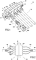
- the connector 10 includes a housing 20 and four cable tie assemblies 30A, 30B, 30C, 30D identical to each other.
- Each cable tie assembly includes a contact (32A, 32B, 32C, 32D), a spring (34A, 34B, 34C, 34D), and a sleeve (36A, 36B, 36C, 36D).
- the connector 10 constitutes a first connector designed to be fixed to a corresponding second connector 110 ( Fig. 2 ).
- the connector 10 can be connected to four cables 40.
- the connector 110 is on its side connected to four cables 140, the connectors 10 and 110 together make it possible to connect the four cables 40 to the four cables 140 in parallel.
- the cables 40 are assembled, away from the connector 10, in a sheath 41;
- the cables 140 are assembled, away from the connector 110, in a sheath 141.
- the box 20 is fixed to the box 120 by screws 44.
- connector 10 A relatively important difference between connector 10 and connector 110 is that in connector 10 the contacts are 'spring-loaded', whereas in connector 110 the contacts are fixed, i.e. maintained in a fixed position relative to the housing 120.
- the housing 20 is a housing made in two parts. It comprises an insert 21 made of injected and / or machined plastic, placed inside a shell 23 made of aluminum manufactured by machining ( Fig. 3 ). It has a platform 22, the ends of which are crossed by two screws 44 which serve to fix the connector 10 on the connector 110.
- the housing 20 has the general shape of a rectangular parallelepiped arranged between a front face 24 and a rear face 25.
- the rear face 25 is pierced by a wide opening serving to pass the fixing assemblies 30.
- the four fixing assemblies 30 being identical, the description of the connector 10 will be made simply by referring to the assembly 30A.
- Cable tie assembly 30A includes contact 32A, spring 34A, and sleeve 36A ( Fig. 1 , 3 ). It is used to fix the 40A cable to the box 20.
- the 40A cable consists of a single copper electrical conductor.
- the contact 32A is a contact also formed from copper by turning, and crimped at the end of the cable 40A.
- the front end 31A of the contact 32A is formed with four tabs 31A1,31A2,31A3,31A4 provided to fit inside a corresponding contact of the connector 110.
- the rear end 33A of the contact 32A has the shape of a sleeve, that is to say of a hollow cylinder.
- the internal bore is occupied by the end of the cable 40A, this cylindrical part 33A being precisely crimped onto the end of the cable.
- the spring 34A is disposed around the cylinder 33A.
- the contact 32A has a flange 35A.
- this flange On the rear side, this flange has a surface 37A, the normal of which is directed in the rear direction. This surface constitutes a contact spring bearing surface: it is on it that the front end of the spring 34A rests.
- the sleeve 36A has by definition the general shape of a hollow cylinder.
- the internal bore which passes through it in the direction of insertion (in the mounted position) has a first part, the diameter of which is slightly larger than the external diameter of the spring 34A, and which serves precisely to receive the spring 34A. Further back, this larger diameter bore portion extends to a smaller diameter bore portion, the diameter of which simply serves to pass the cable 40A with play.
- a spring bearing surface 38A is formed on which the rear end of the spring 34A rests.
- the outer surface of the sleeve 36A is illustrated in particular by the figure 1 . At its rear end, it comprises fins 39A which serve to hold the sleeve and in particular to rotate it when it is put in place, as will be described below.
- the outer surface of the sleeve 36A has two lugs 42 for axial locking.
- These lugs are arranged projecting on the outer surface of the sleeve 36A. They make it possible to prevent an axial displacement of the sleeve relative to the housing 20 towards the rear as follows.
- the shape of the housing 26 and of its opening is defined by its outer contour 27.
- the housing 26 is arranged so as to receive (in part) the contact fixing assemblies 30. It notably maintains the cylindrical parts of the sleeves. 36 by blocking all the degrees of freedom of these sleeves except for each the translation with respect to the axis of the fixing assembly of which it is part and the rotation about this axis. This maintenance is provided by cylindrical surfaces 49 arranged in the housing 26 which constitute the guide surfaces within the meaning of the invention.
- the diameter of the guide surfaces 49 is fixed so that the four sleeves 36 can pass into the contour 27 to fit into the housing 26.
- the lugs 42 can penetrate into the housing 26.
- the contour 27 has projecting parts 28 (most of them are in an arc) which project outwardly and allow the passage of the lugs 42.
- the interior of the housing 26 is provided so that the lugs 42 can penetrate inside the housing when a cable fixing assembly 30 is mounted in the housing 20.
- the connection of the mounting assemblies to the housing is of the bayonet type.
- the mounting of a cable fixing assembly 30, for example the assembly 30A, in the connector 10 is done by carrying out the following operations.
- a first step ( Figs. 3A, 3B and 3C ) the cable fixing assembly 30A is moved in translation along the insertion direction until the sleeve reaches a first insertion position in which the lugs 42A butt against a surface 29A of the housing. Throughout this translation, the sleeve remains in the angular insertion position. In this position, the lug 42A forms an angle ⁇ 1 with respect to the horizontal direction shown on the figure 3A .
- the sleeve 36 is then rotated by hand until it reaches the final angular position, illustrated in the figure. Fig. 4 (angle ⁇ 2). This rotational movement is blocked when the lugs 42A come into abutment against the internal wall of the housing 26 (arrow A, Fig. 5 ). Following this rotation, the lugs 42A are found placed, in view from the rear direction, at least partly behind a part 48 located at the rear 25 of the housing 20 and which is located opposite a part of the surface 29A .
- this part 48 of the housing 20 serves to prevent the sleeve 36 from retracting rearwardly, as will be shown in connection with the figures 5 and 6 .
- the connector 20 in fact comprises a latching mechanism which maintains the fixing assembly 30 in the mounted position.
- This latching mechanism consists mainly of the spring 34, and the various surfaces and structures which allow them to transmit their restoring force: towards the front, on the contact 32, the spring bearing surface 37; towards the rear, the spring bearing surfaces 38 formed on the sleeve, the axial locking pins 42 of the sleeve 36, cooperating with the part 48 of the housing 20.
- the locking step makes it possible to place the cable fixing assembly in the mounted position and to ensure the axial locking and the rotation locking of the sleeve 36, as follows.
- the sleeve 36A includes references 45A. These marks are constituted in this embodiment by short axial ribs protruding from the outer surface of the sleeve 36A. These axial ribs or references 45A extend rearwardly from the lugs 42A. In particular, in rear view (as seen on the Fig. 1 ) these references 45A fit inside the surface occupied by the pins 42A.
- markers 45A are inserted entirely inside the housing 26.
- the housing 26 is provided with grooves 50 arranged to allow the passage of the marks 45 as follows.
- the sleeve 36A is released. As the spring 34A exerts a rearward force on the sleeve 36A, the latter then moves back until the lugs 42A lock against an axial sleeve locking surface 47A provided inside the housing 26 on the sleeve. part 48 ( Fig. 6 ). The sleeve 36A is then axially locked in its final axial position (mounted position). Due to this backward movement (arrow B in the detail view of the figure 6 ), the marks 45A which until then were entirely inside the housing 20 protrude slightly from the latter, as can be seen for the marks 45B, 45C and 45D on the Fig. 1 . The operator who is in the process of mounting the cable fixing assembly 30A can thus check that the sleeve 36A which he has just fitted has positioned itself correctly.
- the marks 45 provide not only an assembly indicator function, but also a rotation locking function. Indeed, during the retraction of the sleeve 36A to reach the final axial position, the marks 45A are introduced into the corresponding grooves 50 arranged inside the housing 26 to accommodate them. These grooves match (with clearance) the external shape of the reference marks 45A and consequently, prevent any rotation of the sleeve 36A. The sleeve 36A is thus prevented from rotating, for example as a result of vibrations, to find itself in the angular position reached at the end of the first assembly step (angle ⁇ 1) in which the sleeve 36A could possibly come out of the housing 26.
- the various figures clearly show the compactness of the connector 10.
- the fixing assemblies 30 are all inserted via a single opening, delimited on the rear face 25 of the housing 26 by its outline 27.
- the parts of the sleeves 36 closest to each other are directly opposite each other, that is to say more precisely are not separated by any partition of the housing 20. Thanks to to this, the center distance d between the sleeves 36 can be reduced to a very low value, in particular a value less than 1.2 D where D is the outside diameter of the sleeves 36.
Landscapes
- Physics & Mathematics (AREA)
- General Physics & Mathematics (AREA)
- Optics & Photonics (AREA)
- Details Of Connecting Devices For Male And Female Coupling (AREA)
- Connector Housings Or Holding Contact Members (AREA)
- Mechanical Coupling Of Light Guides (AREA)
Claims (13)
- Verbinder (10), umfassend ein Gehäuse (20) und wenigstens eine erste und eine zweite Kabelbefestigungsanordnung (30), wobeidas Gehäuse (20) eine innere Aufnahme (26) aufweist, die über eine Öffnung in eine Rückseite (25) des Gehäuses mündet,wobei eine jeder der ersten und der zweiten Kabelbefestigungsanordnung eine Achse (X) aufweist und einen Kontakt (32) und eine Hülse (36) umfasst, wobei der Kontakt (32) dazu ausgelegt ist, an einem Ende eines Kabels (40) befestigt zu werden, das zuvor durch die Hülse (36) geführt wurde,der Verbinder für eine jede der ersten und der zweiten Kabelbefestigungsanordnung (30) eine Bajonettverbindung aufweist, die wenigstens eine in dem Gehäuse ausgebildete Führungsfläche (49) aufweist und ermöglicht, die Kabelbefestigungsanordnung (30) wenigstens teilweise in der inneren Aufnahme des Gehäuses anzubringen, unddas Gehäuse sowie die erste und die zweite Kabelbefestigungsanordnung derart ausgelegt sind, dass bei der Montage die erste und die zweite Kabelbefestigungsanordnung durch die gemeinsame Öffnung in das Gehäuse eingeführt werden.
- Verbinder nach Anspruch 1, bei dem für eine jede der ersten und der zweiten Kabelbefestigungsanordnung (30):- die Kabelbefestigungsanordnung (30) und das Gehäuse (20) so angeordnet sind, dass, wenn die Kabelbefestigungsanordnung wenigstens teilweise in der inneren Aufnahme des Gehäuses angebracht ist, die wenigstens eine Führungsfläche (49) mit der Hülse (36) zusammenwirkt, um alle Freiheitsgrade der Hülse außer einer Verschiebung gegenüber der Achse der Befestigungsanordnung und einer Drehung um diese Achse zu blockieren.
- Verbinder nach Anspruch 2, bei dem bei jeder der ersten und zweiten Kabelbefestigungsanordnung (30), im Bereich axial von der wenigstens einen Führungsfläche (49), die wenigstens eine Führungsfläche der betrachteten Kabelbefestigungsanordnung sich nur über einen Teil des Umfangs der Hülse (36) erstreckt, und Abschnitte der Hülsen der ersten und der zweiten Kabelbefestigungsanordnung, die einander am nächsten liegen, direkt einander gegenüberliegen, wobei sie durch keine Trennwand des Gehäuses (20) voneinander getrennt sind.
- Verbinder nach Anspruch 2 oder 3, dadurch gekennzeichnet, dass sich die wenigstens eine Führungsfläche (49) in Einführrichtung gesehen, wenigstens für eine der Kabelbefestigungsanordnungen, über zwei einander gegenüberliegende Winkelsektoren (S1, S2) erstreckt.
- Verbinder nach einem der Ansprüche 1 bis 4, umfassend für wenigstens eine der ersten und der zweiten Kabelbefestigungsanordnung (30) einen Einrastmechanismus, welcher der Kabelbefestigungsanordnung (30) am Ende der Montage ermöglicht, in montierter Position eingerastet und somit in gegenüber dem Gehäuse (20) fester Position gehalten zu werden.
- Verbinder nach Anspruch 5, bei dem für wenigstens eine der ersten und der zweiten Kabelbefestigungsanordnung (30):der Einrastmechanismus eine Feder (34) umfasst,der Kontakt (32) dazu ausgelegt ist, dass er, nachdem er an dem Ende des zuvor durch die Hülse (36) geführten Kabels (40) befestigt worden ist, dann in einer Einführrichtung (X) entlang der Achse der Befestigungsanordnung unter Durchqueren der Öffnung der Rückseite des Gehäuses (20) angebracht wird,die Kabelbefestigungsanordnung (30) und das Gehäuse (20) so angeordnet sind, dass die Feder (34) dann, wenn die Kabelbefestigungsanordnung sich in montierter Position befindet, eingefedert wird und am Gehäuse (20) anliegend in Einführrichtung auf den Kontakt (32) drückt und in der Folge den Kontakt gegenüber dem Gehäuse in der Einführrichtung axial blockiert.
- Verbinder nach Anspruch 6, bei dem der Kontakt (32) eine Kontakt-Federanlagefläche (37) aufweist, die so angeordnet ist, dass die Feder (34), welche um das Ende des Kabels (40) herum angeordnet ist, eine Druckkraft an die Kontakt-Federanlagefläche (37) in einer axialen Richtung davon anlegen kann.
- Verbinder nach Anspruch 6 oder 7, bei demdie Hülse wenigstens einen Nocken (42) zum axialen Blockieren aufweist, der an ihrer Außenfläche vorspringend angeordnet ist; unddas Gehäuse und die betrachtete Kabelbefestigungsanordnung derart ausgestaltet sind, dass in montierter Position, unter der Wirkung des Drucks der Feder (34), die Hülse (36) nach hinten in die montierte Position gedrückt wird, in welcher der wenigstens eine Nocken (42) zum axialen Blockieren an wenigstens einer Fläche (47) zum axialen Blockieren der Hülse des Gehäuses anliegt, die den wenigstens einen Nocken (42) zum axialen Blockieren nach hinten sperrt und somit jegliche Bewegung der Hülse (36) nach hinten verhindert.
- Verbinder nach Anspruch 8, bei dem die Hülse (36) der betrachteten Kabelbefestigungsanordnung und das Gehäuse (20) so ausgelegt sind, dass:- die in eine erste Winkelstellung (α1) gebrachte Hülse der betrachteten Kabelbefestigungsanordnung entlang der Einführrichtung in die Aufnahme (26) des Gehäuses eingeführt werden kann, dann- die Hülse (36) veranlasst werden kann, sich um die Achse der Befestigungsanordnung zu drehen, um eine zweite Winkelposition (α2) zu erreichen, in der die wenigstens eine Fläche (47) zum axialen Blockieren der Hülse des Gehäuses den wenigstens einen Nocken (42) zum axialen Blockieren nach hinten sperrt.
- Verbinder nach einem der Ansprüche 1 bis 9, bei dem wenigstens für eine betrachtete Kabelbefestigungsanordnung (30) die Hülse (36) der betrachteten Kabelbefestigungsanordnung und das Gehäuse (20) so ausgelegt sind, dass:- das Gehäuse wenigstens eine Drehblockierfläche (50) aufweist, die nicht um die Einführrichtung (X) umlaufend ist, und- die Hülse (30) wenigstens einen Verdrehsicherungsnocken (45) aufweist, der an ihrer Außenfläche vorspringend angeordnet ist, unddie betrachtete Kabelbefestigungsanordnung (30) und das Gehäuse (20) so angeordnet sind, dass bei der Montage der betrachteten Kabelbefestigungsanordnung (30) wenigstens teilweise in der inneren Aufnahme des Gehäuses:- die Kabelbefestigungsanordnung in die Aufnahme (26) des Gehäuses in Einführrichtung durch die Öffnung des Gehäuses eingeführt wird, bis die Hülse axial eine erste axiale Position (X1) und winkelmäßig eine erste Winkelposition (α1) erreicht, anschließend- die Hülse (36) sich nun um die Achse der Befestigungsanordnung dreht, um eine zweite Winkelposition (α2) zu erreichen,- die Hülse nun axial gegenüber dem Gehäuse gleitet, um eine zweite axiale Position (X2) zu erreichen, die hinter der ersten axialen Position gelegen ist, und- wenn sich die Hülse in der zweiten axialen Position (X2) befindet, der Verdrehsicherungsnocken mit der wenigstens einen Drehblockierfläche (50) zusammenwirkt, um eine Drehung der Hülse um die Achse der Befestigungsanordnung zu verhindern.
- Verbinder nach Anspruch 10, bei dem wenigstens für die betrachtete Kabelbefestigungsanordnung (30) die Hülse eine Markierung (45) aufweist, die Kabelbefestigungsanordnung (30) und die Hülse (36) derart ausgelegt sind, dass dann, wenn sich die Hülse (36) in der ersten axialen Position (X1) befindet, die Markierung auf einer Rückseite des Gehäuses nicht sichtbar ist, während dann, wenn sich die Hülse (36) in der zweiten axialen Position (X2) befindet, die Markierung (45) sichtbar ist und vorzugsweise an der Rückseite des Gehäuses vorsteht.
- Verbinder nach Anspruch 11, bei dem die Markierung (45) eine Farbmarkierung, die auf der Außenfläche der Hülse (36) vorgesehen ist, und/oder ein Vorsprung ist, der an der Außenfläche ausgebildet ist.
- Verbinder nach einem der Ansprüche 1 bis 12, bei dem der Kontakt (32) ein Kontakt für einen oder mehrere elektrische Leiter und/oder einen oder mehrere Lichtwellenleiter ist.
Applications Claiming Priority (1)
| Application Number | Priority Date | Filing Date | Title |
|---|---|---|---|
| FR1754572A FR3066861B1 (fr) | 2017-05-23 | 2017-05-23 | Connecteur quart de tour compact |
Publications (2)
| Publication Number | Publication Date |
|---|---|
| EP3407431A1 EP3407431A1 (de) | 2018-11-28 |
| EP3407431B1 true EP3407431B1 (de) | 2021-11-10 |
Family
ID=59297111
Family Applications (1)
| Application Number | Title | Priority Date | Filing Date |
|---|---|---|---|
| EP18173290.0A Active EP3407431B1 (de) | 2017-05-23 | 2018-05-18 | Kompaktstecker |
Country Status (5)
| Country | Link |
|---|---|
| US (1) | US10498067B2 (de) |
| EP (1) | EP3407431B1 (de) |
| JP (1) | JP7141852B2 (de) |
| CN (1) | CN108933354B (de) |
| FR (1) | FR3066861B1 (de) |
Families Citing this family (7)
| Publication number | Priority date | Publication date | Assignee | Title |
|---|---|---|---|---|
| US10422965B2 (en) * | 2018-01-26 | 2019-09-24 | Steve Cheng | Fiber optic connector |
| FR3108203B1 (fr) * | 2020-03-11 | 2023-06-02 | Axon Cable Sa | Ensemble de connexion à fixation rapide et sécurisée |
| CN112099154B (zh) * | 2020-09-04 | 2022-03-08 | 华为技术有限公司 | 光纤插头、光纤连接器及光纤连接系统 |
| WO2022119632A1 (en) * | 2020-12-02 | 2022-06-09 | Commscope Technologies Llc | Ganged coaxial connector assembly with removable connector-cable configuration |
| CN113031169B (zh) * | 2021-05-26 | 2021-08-31 | 中天宽带技术有限公司 | 预制连接器、耦合器及预制连接器组件 |
| DE102021134299A1 (de) * | 2021-12-22 | 2023-06-22 | Te Connectivity Germany Gmbh | Elektrischer Steckverbinder und Verfahren zum Montieren eines elektrischen Steckverbinders |
| CN115421252B (zh) * | 2022-09-01 | 2023-08-11 | 烽火通信科技股份有限公司 | 一种适配器、连接器及光纤连接盒 |
Citations (2)
| Publication number | Priority date | Publication date | Assignee | Title |
|---|---|---|---|---|
| DE202006012880U1 (de) * | 2006-08-22 | 2007-12-27 | Wieland Electric Gmbh | Elektrisch isolierendes Gehäuse |
| DE112011104520T5 (de) * | 2010-12-22 | 2013-10-24 | Japan Aviation Electronics Industry, Ltd. | Stecker |
Family Cites Families (25)
| Publication number | Priority date | Publication date | Assignee | Title |
|---|---|---|---|---|
| US151432A (en) * | 1874-05-26 | Improvement in head-blocks for saw-mills | ||
| US3308420A (en) * | 1964-12-21 | 1967-03-07 | United Carr Inc | Lamp socket shell with integral tangs |
| US4834487A (en) * | 1988-09-29 | 1989-05-30 | Amp Incorporated | Optical connector with plastic alignment ferrule |
| US4989867A (en) * | 1989-05-18 | 1991-02-05 | Herrick Robert M | Damped tennis practice device |
| US5067783A (en) * | 1990-10-16 | 1991-11-26 | At&T Bell Laboratories | Optical fiber connector buildout system |
| US5031981A (en) * | 1990-11-15 | 1991-07-16 | Amp Incorporated | Attachment and disengagement tool for bayonet type optical fiber connector |
| US5363459A (en) * | 1993-01-15 | 1994-11-08 | The Whitaker Corporation | Optical fiber connector including a biasing means in housing |
| TW334180U (en) * | 1993-04-22 | 1998-06-11 | Whitaker Corp | High density connector |
| JP3066739B2 (ja) * | 1996-07-15 | 2000-07-17 | セイコーインスツルメンツ株式会社 | 汎用光コネクタ及びベーシックプラグ |
| JPH11160572A (ja) * | 1997-11-28 | 1999-06-18 | Kyocera Corp | 光ファイバコネクタ用フェルール |
| JP3775709B2 (ja) * | 1998-09-10 | 2006-05-17 | 矢崎総業株式会社 | 端子金具 |
| US6572276B1 (en) * | 2000-11-21 | 2003-06-03 | Euromicron Werkezeuge Gmbh | Plug for fiber optic cables with a plug housing |
| JP2006012573A (ja) * | 2004-06-25 | 2006-01-12 | Jst Mfg Co Ltd | 電気的接続装置 |
| JP4274222B2 (ja) * | 2006-10-02 | 2009-06-03 | パナソニック電工株式会社 | 光電変換コネクタ及びその製造方法 |
| US7607929B1 (en) * | 2008-06-30 | 2009-10-27 | Tyco Electronics Corporation | Electrical connector assembly having spring loaded electrical connector |
| US7955142B1 (en) * | 2010-01-20 | 2011-06-07 | Tyco Electronics Corporation | Rotatable secondary lock for electrical connector |
| CN201946850U (zh) * | 2010-12-15 | 2011-08-24 | 中航光电科技股份有限公司 | 一种防止接触件倾斜的同轴连接器 |
| US8998506B2 (en) * | 2012-09-14 | 2015-04-07 | 3M Innovative Properties Company | Field terminable ST format optical fiber connector |
| DE102013209533A1 (de) * | 2013-05-23 | 2014-11-27 | Robert Bosch Gmbh | Elemente für eine mechanische und elektrische Verbindung |
| JP6106544B2 (ja) * | 2013-07-02 | 2017-04-05 | 矢崎総業株式会社 | 回転式コネクタ |
| US9618704B2 (en) * | 2013-07-31 | 2017-04-11 | Corning Optical Communications LLC | Fiber optic connector sub-assemblies having a front-loading locking ferrule holder and related fiber optic components, devices and methods |
| CN103972749B (zh) * | 2014-04-04 | 2016-06-01 | 武汉德威斯电子技术有限公司 | 一种多头电缆连接器 |
| EP3391115A4 (de) * | 2015-12-16 | 2019-07-17 | Commscope Technologies LLC | Am einsatzort installierter glasfaserverbinder |
| JP6898710B2 (ja) * | 2016-04-04 | 2021-07-07 | ヒロセ電機株式会社 | 光コネクタおよび光ファイバケーブル接続方法 |
| CN205790707U (zh) * | 2016-07-05 | 2016-12-07 | 陕西华达科技股份有限公司 | 混装及模块电连接器用新型浮动盲插同轴接触件 |
-
2017
- 2017-05-23 FR FR1754572A patent/FR3066861B1/fr active Active
-
2018
- 2018-05-18 EP EP18173290.0A patent/EP3407431B1/de active Active
- 2018-05-22 JP JP2018097684A patent/JP7141852B2/ja active Active
- 2018-05-22 US US15/986,012 patent/US10498067B2/en active Active
- 2018-05-23 CN CN201810501076.0A patent/CN108933354B/zh active Active
Patent Citations (2)
| Publication number | Priority date | Publication date | Assignee | Title |
|---|---|---|---|---|
| DE202006012880U1 (de) * | 2006-08-22 | 2007-12-27 | Wieland Electric Gmbh | Elektrisch isolierendes Gehäuse |
| DE112011104520T5 (de) * | 2010-12-22 | 2013-10-24 | Japan Aviation Electronics Industry, Ltd. | Stecker |
Also Published As
| Publication number | Publication date |
|---|---|
| CN108933354A (zh) | 2018-12-04 |
| US10498067B2 (en) | 2019-12-03 |
| EP3407431A1 (de) | 2018-11-28 |
| FR3066861A1 (fr) | 2018-11-30 |
| JP7141852B2 (ja) | 2022-09-26 |
| FR3066861B1 (fr) | 2020-10-30 |
| US20180366861A1 (en) | 2018-12-20 |
| JP2018198203A (ja) | 2018-12-13 |
| CN108933354B (zh) | 2021-12-21 |
Similar Documents
| Publication | Publication Date | Title |
|---|---|---|
| EP3407431B1 (de) | Kompaktstecker | |
| EP2071677B1 (de) | Anschluss an Anti-Entriegelungssysteme | |
| EP2315315B1 (de) | Koaxialer sockel | |
| CA1329420C (fr) | Connecteur electrique | |
| FR2758662A1 (fr) | Element de connecteur electrique coaxial a contact mobile et connecteur electrique coaxial comprenant un tel element de connecteur | |
| FR3031245A1 (fr) | Ensemble de connexion a verrouillage par baionnette des elements de connexion | |
| WO2007132133A1 (fr) | Système de verrouillage d'un premier arbre par rapport à un deuxième arbre supprimant les jeux entre lesdits arbres | |
| EP1732180B1 (de) | Befestigungsanordnung für einen zweiteiligen Steckverbinder und entsprechender zweiteiliger Steckverbinder | |
| FR3049778A1 (fr) | Connecteur electrique a dispositif d'assurance de position de connecteur rotatif | |
| FR2756978A1 (fr) | Connecteur circulaire modulaire | |
| EP0476024B1 (de) | Verbindung für glasfasern | |
| EP3879639B1 (de) | Steckverbinder mit einem im gehäuse drehbar montierten und durch ein werkzeug betätigbaren zwischenstück zum schieben eines verriegelungsdeckels auf einen komplementären steckverbinder | |
| EP3796481B1 (de) | Steckverbinder mit spielausgleich, verbindungsvorrichtung und anordnung mit einer solchen vorrichtung | |
| FR2886775A1 (fr) | Prise de courant a fond de puits mobile et obturateur escamotable | |
| EP1670301A1 (de) | Verbindungsanordnung bestehend aus einem Halter mit einer Öffnung und einem Verbindergehäuse montiert auf dem Halter | |
| EP1147574B1 (de) | Koaxiale kabelverbindungseinrichtung | |
| FR3061562B1 (fr) | Dispositif de raccordement amovible pour un guide de lumiere et application dans un vehicule automobile, module a transmission optique pourvu du dispositif | |
| FR2540670A3 (fr) | Appareil electrique muni d'au moins une cartouche coupe-circuit | |
| EP3879638B1 (de) | Verbindungseinheit mit gesicherter schnellbefestigung | |
| EP0628681B1 (de) | Vorrichtung zusammengebaut aus einem Schloss und seiner Betätigungsnocke | |
| EP4191796A1 (de) | Tastenanordnung zum automatischen trennen von anschlüssen, gerätemechanismus mit dieser anordnung und verfahren zur herstellung der anordnung | |
| EP0340066B1 (de) | Elektrischer Verbinder | |
| EP0141735A2 (de) | Elektrische Verbindungssicherheitseinrichtung mit einem Schliessschieber, insbesondere als Steckdose zu gebrauchen | |
| FR2632458A1 (fr) | Connecteur electrique | |
| FR2678113A1 (fr) | Systeme de connecteur electrique. |
Legal Events
| Date | Code | Title | Description |
|---|---|---|---|
| PUAI | Public reference made under article 153(3) epc to a published international application that has entered the european phase |
Free format text: ORIGINAL CODE: 0009012 |
|
| STAA | Information on the status of an ep patent application or granted ep patent |
Free format text: STATUS: THE APPLICATION HAS BEEN PUBLISHED |
|
| AK | Designated contracting states |
Kind code of ref document: A1 Designated state(s): AL AT BE BG CH CY CZ DE DK EE ES FI FR GB GR HR HU IE IS IT LI LT LU LV MC MK MT NL NO PL PT RO RS SE SI SK SM TR |
|
| AX | Request for extension of the european patent |
Extension state: BA ME |
|
| STAA | Information on the status of an ep patent application or granted ep patent |
Free format text: STATUS: REQUEST FOR EXAMINATION WAS MADE |
|
| 17P | Request for examination filed |
Effective date: 20190527 |
|
| RBV | Designated contracting states (corrected) |
Designated state(s): AL AT BE BG CH CY CZ DE DK EE ES FI FR GB GR HR HU IE IS IT LI LT LU LV MC MK MT NL NO PL PT RO RS SE SI SK SM TR |
|
| STAA | Information on the status of an ep patent application or granted ep patent |
Free format text: STATUS: EXAMINATION IS IN PROGRESS |
|
| 17Q | First examination report despatched |
Effective date: 20200512 |
|
| RIC1 | Information provided on ipc code assigned before grant |
Ipc: H01R 13/434 20060101AFI20210421BHEP Ipc: H01R 13/426 20060101ALI20210421BHEP Ipc: G02B 6/38 20060101ALI20210421BHEP Ipc: H01R 13/621 20060101ALN20210421BHEP Ipc: H01R 13/74 20060101ALN20210421BHEP Ipc: H01R 107/00 20060101ALN20210421BHEP Ipc: H01R 13/625 20060101ALN20210421BHEP |
|
| RIC1 | Information provided on ipc code assigned before grant |
Ipc: H01R 13/434 20060101AFI20210423BHEP Ipc: H01R 13/426 20060101ALI20210423BHEP Ipc: G02B 6/38 20060101ALI20210423BHEP Ipc: H01R 13/621 20060101ALN20210423BHEP Ipc: H01R 13/74 20060101ALN20210423BHEP Ipc: H01R 107/00 20060101ALN20210423BHEP Ipc: H01R 13/625 20060101ALN20210423BHEP |
|
| GRAP | Despatch of communication of intention to grant a patent |
Free format text: ORIGINAL CODE: EPIDOSNIGR1 |
|
| STAA | Information on the status of an ep patent application or granted ep patent |
Free format text: STATUS: GRANT OF PATENT IS INTENDED |
|
| RIC1 | Information provided on ipc code assigned before grant |
Ipc: H01R 13/434 20060101AFI20210608BHEP Ipc: H01R 13/426 20060101ALI20210608BHEP Ipc: G02B 6/38 20060101ALI20210608BHEP Ipc: H01R 13/621 20060101ALN20210608BHEP Ipc: H01R 13/74 20060101ALN20210608BHEP Ipc: H01R 107/00 20060101ALN20210608BHEP Ipc: H01R 13/625 20060101ALN20210608BHEP |
|
| INTG | Intention to grant announced |
Effective date: 20210623 |
|
| GRAS | Grant fee paid |
Free format text: ORIGINAL CODE: EPIDOSNIGR3 |
|
| GRAA | (expected) grant |
Free format text: ORIGINAL CODE: 0009210 |
|
| STAA | Information on the status of an ep patent application or granted ep patent |
Free format text: STATUS: THE PATENT HAS BEEN GRANTED |
|
| AK | Designated contracting states |
Kind code of ref document: B1 Designated state(s): AL AT BE BG CH CY CZ DE DK EE ES FI FR GB GR HR HU IE IS IT LI LT LU LV MC MK MT NL NO PL PT RO RS SE SI SK SM TR |
|
| REG | Reference to a national code |
Ref country code: GB Ref legal event code: FG4D Free format text: NOT ENGLISH |
|
| REG | Reference to a national code |
Ref country code: AT Ref legal event code: REF Ref document number: 1446937 Country of ref document: AT Kind code of ref document: T Effective date: 20211115 Ref country code: CH Ref legal event code: EP |
|
| REG | Reference to a national code |
Ref country code: DE Ref legal event code: R096 Ref document number: 602018026340 Country of ref document: DE |
|
| REG | Reference to a national code |
Ref country code: IE Ref legal event code: FG4D Free format text: LANGUAGE OF EP DOCUMENT: FRENCH |
|
| REG | Reference to a national code |
Ref country code: LT Ref legal event code: MG9D |
|
| REG | Reference to a national code |
Ref country code: NL Ref legal event code: MP Effective date: 20211110 |
|
| REG | Reference to a national code |
Ref country code: AT Ref legal event code: MK05 Ref document number: 1446937 Country of ref document: AT Kind code of ref document: T Effective date: 20211110 |
|
| PG25 | Lapsed in a contracting state [announced via postgrant information from national office to epo] |
Ref country code: RS Free format text: LAPSE BECAUSE OF FAILURE TO SUBMIT A TRANSLATION OF THE DESCRIPTION OR TO PAY THE FEE WITHIN THE PRESCRIBED TIME-LIMIT Effective date: 20211110 Ref country code: LT Free format text: LAPSE BECAUSE OF FAILURE TO SUBMIT A TRANSLATION OF THE DESCRIPTION OR TO PAY THE FEE WITHIN THE PRESCRIBED TIME-LIMIT Effective date: 20211110 Ref country code: FI Free format text: LAPSE BECAUSE OF FAILURE TO SUBMIT A TRANSLATION OF THE DESCRIPTION OR TO PAY THE FEE WITHIN THE PRESCRIBED TIME-LIMIT Effective date: 20211110 Ref country code: BG Free format text: LAPSE BECAUSE OF FAILURE TO SUBMIT A TRANSLATION OF THE DESCRIPTION OR TO PAY THE FEE WITHIN THE PRESCRIBED TIME-LIMIT Effective date: 20220210 Ref country code: AT Free format text: LAPSE BECAUSE OF FAILURE TO SUBMIT A TRANSLATION OF THE DESCRIPTION OR TO PAY THE FEE WITHIN THE PRESCRIBED TIME-LIMIT Effective date: 20211110 |
|
| PG25 | Lapsed in a contracting state [announced via postgrant information from national office to epo] |
Ref country code: IS Free format text: LAPSE BECAUSE OF FAILURE TO SUBMIT A TRANSLATION OF THE DESCRIPTION OR TO PAY THE FEE WITHIN THE PRESCRIBED TIME-LIMIT Effective date: 20220310 Ref country code: SE Free format text: LAPSE BECAUSE OF FAILURE TO SUBMIT A TRANSLATION OF THE DESCRIPTION OR TO PAY THE FEE WITHIN THE PRESCRIBED TIME-LIMIT Effective date: 20211110 Ref country code: PT Free format text: LAPSE BECAUSE OF FAILURE TO SUBMIT A TRANSLATION OF THE DESCRIPTION OR TO PAY THE FEE WITHIN THE PRESCRIBED TIME-LIMIT Effective date: 20220310 Ref country code: PL Free format text: LAPSE BECAUSE OF FAILURE TO SUBMIT A TRANSLATION OF THE DESCRIPTION OR TO PAY THE FEE WITHIN THE PRESCRIBED TIME-LIMIT Effective date: 20211110 Ref country code: NO Free format text: LAPSE BECAUSE OF FAILURE TO SUBMIT A TRANSLATION OF THE DESCRIPTION OR TO PAY THE FEE WITHIN THE PRESCRIBED TIME-LIMIT Effective date: 20220210 Ref country code: NL Free format text: LAPSE BECAUSE OF FAILURE TO SUBMIT A TRANSLATION OF THE DESCRIPTION OR TO PAY THE FEE WITHIN THE PRESCRIBED TIME-LIMIT Effective date: 20211110 Ref country code: LV Free format text: LAPSE BECAUSE OF FAILURE TO SUBMIT A TRANSLATION OF THE DESCRIPTION OR TO PAY THE FEE WITHIN THE PRESCRIBED TIME-LIMIT Effective date: 20211110 Ref country code: HR Free format text: LAPSE BECAUSE OF FAILURE TO SUBMIT A TRANSLATION OF THE DESCRIPTION OR TO PAY THE FEE WITHIN THE PRESCRIBED TIME-LIMIT Effective date: 20211110 Ref country code: GR Free format text: LAPSE BECAUSE OF FAILURE TO SUBMIT A TRANSLATION OF THE DESCRIPTION OR TO PAY THE FEE WITHIN THE PRESCRIBED TIME-LIMIT Effective date: 20220211 Ref country code: ES Free format text: LAPSE BECAUSE OF FAILURE TO SUBMIT A TRANSLATION OF THE DESCRIPTION OR TO PAY THE FEE WITHIN THE PRESCRIBED TIME-LIMIT Effective date: 20211110 |
|
| PG25 | Lapsed in a contracting state [announced via postgrant information from national office to epo] |
Ref country code: SM Free format text: LAPSE BECAUSE OF FAILURE TO SUBMIT A TRANSLATION OF THE DESCRIPTION OR TO PAY THE FEE WITHIN THE PRESCRIBED TIME-LIMIT Effective date: 20211110 Ref country code: SK Free format text: LAPSE BECAUSE OF FAILURE TO SUBMIT A TRANSLATION OF THE DESCRIPTION OR TO PAY THE FEE WITHIN THE PRESCRIBED TIME-LIMIT Effective date: 20211110 Ref country code: RO Free format text: LAPSE BECAUSE OF FAILURE TO SUBMIT A TRANSLATION OF THE DESCRIPTION OR TO PAY THE FEE WITHIN THE PRESCRIBED TIME-LIMIT Effective date: 20211110 Ref country code: EE Free format text: LAPSE BECAUSE OF FAILURE TO SUBMIT A TRANSLATION OF THE DESCRIPTION OR TO PAY THE FEE WITHIN THE PRESCRIBED TIME-LIMIT Effective date: 20211110 Ref country code: DK Free format text: LAPSE BECAUSE OF FAILURE TO SUBMIT A TRANSLATION OF THE DESCRIPTION OR TO PAY THE FEE WITHIN THE PRESCRIBED TIME-LIMIT Effective date: 20211110 Ref country code: CZ Free format text: LAPSE BECAUSE OF FAILURE TO SUBMIT A TRANSLATION OF THE DESCRIPTION OR TO PAY THE FEE WITHIN THE PRESCRIBED TIME-LIMIT Effective date: 20211110 |
|
| REG | Reference to a national code |
Ref country code: DE Ref legal event code: R097 Ref document number: 602018026340 Country of ref document: DE |
|
| PLBE | No opposition filed within time limit |
Free format text: ORIGINAL CODE: 0009261 |
|
| STAA | Information on the status of an ep patent application or granted ep patent |
Free format text: STATUS: NO OPPOSITION FILED WITHIN TIME LIMIT |
|
| 26N | No opposition filed |
Effective date: 20220811 |
|
| PG25 | Lapsed in a contracting state [announced via postgrant information from national office to epo] |
Ref country code: AL Free format text: LAPSE BECAUSE OF FAILURE TO SUBMIT A TRANSLATION OF THE DESCRIPTION OR TO PAY THE FEE WITHIN THE PRESCRIBED TIME-LIMIT Effective date: 20211110 |
|
| PG25 | Lapsed in a contracting state [announced via postgrant information from national office to epo] |
Ref country code: SI Free format text: LAPSE BECAUSE OF FAILURE TO SUBMIT A TRANSLATION OF THE DESCRIPTION OR TO PAY THE FEE WITHIN THE PRESCRIBED TIME-LIMIT Effective date: 20211110 |
|
| REG | Reference to a national code |
Ref country code: CH Ref legal event code: PL |
|
| REG | Reference to a national code |
Ref country code: BE Ref legal event code: MM Effective date: 20220531 |
|
| PG25 | Lapsed in a contracting state [announced via postgrant information from national office to epo] |
Ref country code: MC Free format text: LAPSE BECAUSE OF FAILURE TO SUBMIT A TRANSLATION OF THE DESCRIPTION OR TO PAY THE FEE WITHIN THE PRESCRIBED TIME-LIMIT Effective date: 20211110 Ref country code: LU Free format text: LAPSE BECAUSE OF NON-PAYMENT OF DUE FEES Effective date: 20220518 Ref country code: LI Free format text: LAPSE BECAUSE OF NON-PAYMENT OF DUE FEES Effective date: 20220531 Ref country code: CH Free format text: LAPSE BECAUSE OF NON-PAYMENT OF DUE FEES Effective date: 20220531 |
|
| REG | Reference to a national code |
Ref country code: DE Ref legal event code: R082 Ref document number: 602018026340 Country of ref document: DE Representative=s name: CBDL PATENTANWAELTE GBR, DE Ref country code: DE Ref legal event code: R082 Ref document number: 602018026340 Country of ref document: DE Representative=s name: CBDL PATENTANWAELTE EGBR, DE |
|
| PG25 | Lapsed in a contracting state [announced via postgrant information from national office to epo] |
Ref country code: IE Free format text: LAPSE BECAUSE OF NON-PAYMENT OF DUE FEES Effective date: 20220518 |
|
| PG25 | Lapsed in a contracting state [announced via postgrant information from national office to epo] |
Ref country code: IT Free format text: LAPSE BECAUSE OF FAILURE TO SUBMIT A TRANSLATION OF THE DESCRIPTION OR TO PAY THE FEE WITHIN THE PRESCRIBED TIME-LIMIT Effective date: 20211110 Ref country code: BE Free format text: LAPSE BECAUSE OF NON-PAYMENT OF DUE FEES Effective date: 20220531 |
|
| P01 | Opt-out of the competence of the unified patent court (upc) registered |
Effective date: 20230512 |
|
| PG25 | Lapsed in a contracting state [announced via postgrant information from national office to epo] |
Ref country code: HU Free format text: LAPSE BECAUSE OF FAILURE TO SUBMIT A TRANSLATION OF THE DESCRIPTION OR TO PAY THE FEE WITHIN THE PRESCRIBED TIME-LIMIT; INVALID AB INITIO Effective date: 20180518 |
|
| PG25 | Lapsed in a contracting state [announced via postgrant information from national office to epo] |
Ref country code: MK Free format text: LAPSE BECAUSE OF FAILURE TO SUBMIT A TRANSLATION OF THE DESCRIPTION OR TO PAY THE FEE WITHIN THE PRESCRIBED TIME-LIMIT Effective date: 20211110 Ref country code: CY Free format text: LAPSE BECAUSE OF FAILURE TO SUBMIT A TRANSLATION OF THE DESCRIPTION OR TO PAY THE FEE WITHIN THE PRESCRIBED TIME-LIMIT Effective date: 20211110 |
|
| PG25 | Lapsed in a contracting state [announced via postgrant information from national office to epo] |
Ref country code: TR Free format text: LAPSE BECAUSE OF FAILURE TO SUBMIT A TRANSLATION OF THE DESCRIPTION OR TO PAY THE FEE WITHIN THE PRESCRIBED TIME-LIMIT Effective date: 20211110 |
|
| PG25 | Lapsed in a contracting state [announced via postgrant information from national office to epo] |
Ref country code: MT Free format text: LAPSE BECAUSE OF FAILURE TO SUBMIT A TRANSLATION OF THE DESCRIPTION OR TO PAY THE FEE WITHIN THE PRESCRIBED TIME-LIMIT Effective date: 20211110 |
|
| PGFP | Annual fee paid to national office [announced via postgrant information from national office to epo] |
Ref country code: DE Payment date: 20250513 Year of fee payment: 8 |
|
| PGFP | Annual fee paid to national office [announced via postgrant information from national office to epo] |
Ref country code: GB Payment date: 20250521 Year of fee payment: 8 |
|
| PGFP | Annual fee paid to national office [announced via postgrant information from national office to epo] |
Ref country code: FR Payment date: 20250520 Year of fee payment: 8 |