EP3407511B1 - Rekonfigurierbarer optischer sender - Google Patents
Rekonfigurierbarer optischer sender Download PDFInfo
- Publication number
- EP3407511B1 EP3407511B1 EP18169429.0A EP18169429A EP3407511B1 EP 3407511 B1 EP3407511 B1 EP 3407511B1 EP 18169429 A EP18169429 A EP 18169429A EP 3407511 B1 EP3407511 B1 EP 3407511B1
- Authority
- EP
- European Patent Office
- Prior art keywords
- output
- laser
- input signals
- laser input
- wavelengths
- Prior art date
- Legal status (The legal status is an assumption and is not a legal conclusion. Google has not performed a legal analysis and makes no representation as to the accuracy of the status listed.)
- Active
Links
Images


Classifications
-
- H—ELECTRICITY
- H04—ELECTRIC COMMUNICATION TECHNIQUE
- H04J—MULTIPLEX COMMUNICATION
- H04J14/00—Optical multiplex systems
- H04J14/02—Wavelength-division multiplex systems
- H04J14/0227—Operation, administration, maintenance or provisioning [OAMP] of WDM networks, e.g. media access, routing or wavelength allocation
- H04J14/0254—Optical medium access
- H04J14/0267—Optical signaling or routing
-
- H—ELECTRICITY
- H04—ELECTRIC COMMUNICATION TECHNIQUE
- H04B—TRANSMISSION
- H04B10/00—Transmission systems employing electromagnetic waves other than radio-waves, e.g. infrared, visible or ultraviolet light, or employing corpuscular radiation, e.g. quantum communication
- H04B10/50—Transmitters
- H04B10/501—Structural aspects
- H04B10/503—Laser transmitters
-
- H—ELECTRICITY
- H04—ELECTRIC COMMUNICATION TECHNIQUE
- H04B—TRANSMISSION
- H04B10/00—Transmission systems employing electromagnetic waves other than radio-waves, e.g. infrared, visible or ultraviolet light, or employing corpuscular radiation, e.g. quantum communication
- H04B10/50—Transmitters
- H04B10/501—Structural aspects
- H04B10/506—Multiwavelength transmitters
-
- H—ELECTRICITY
- H04—ELECTRIC COMMUNICATION TECHNIQUE
- H04B—TRANSMISSION
- H04B10/00—Transmission systems employing electromagnetic waves other than radio-waves, e.g. infrared, visible or ultraviolet light, or employing corpuscular radiation, e.g. quantum communication
- H04B10/50—Transmitters
- H04B10/564—Power control
-
- H—ELECTRICITY
- H04—ELECTRIC COMMUNICATION TECHNIQUE
- H04J—MULTIPLEX COMMUNICATION
- H04J14/00—Optical multiplex systems
- H04J14/02—Wavelength-division multiplex systems
- H04J14/0227—Operation, administration, maintenance or provisioning [OAMP] of WDM networks, e.g. media access, routing or wavelength allocation
- H04J14/0254—Optical medium access
- H04J14/0256—Optical medium access at the optical channel layer
- H04J14/0257—Wavelength assignment algorithms
-
- H—ELECTRICITY
- H04—ELECTRIC COMMUNICATION TECHNIQUE
- H04Q—SELECTING
- H04Q11/00—Selecting arrangements for multiplex systems
- H04Q11/0001—Selecting arrangements for multiplex systems using optical switching
- H04Q11/0005—Switch and router aspects
-
- H—ELECTRICITY
- H04—ELECTRIC COMMUNICATION TECHNIQUE
- H04Q—SELECTING
- H04Q11/00—Selecting arrangements for multiplex systems
- H04Q11/0001—Selecting arrangements for multiplex systems using optical switching
- H04Q11/0005—Switch and router aspects
- H04Q2011/0007—Construction
- H04Q2011/0022—Construction using fibre gratings
-
- H—ELECTRICITY
- H04—ELECTRIC COMMUNICATION TECHNIQUE
- H04Q—SELECTING
- H04Q11/00—Selecting arrangements for multiplex systems
- H04Q11/0001—Selecting arrangements for multiplex systems using optical switching
- H04Q11/0005—Switch and router aspects
- H04Q2011/0007—Construction
- H04Q2011/0032—Construction using static wavelength routers (e.g. arrayed waveguide grating router [AWGR] )
-
- H—ELECTRICITY
- H04—ELECTRIC COMMUNICATION TECHNIQUE
- H04Q—SELECTING
- H04Q11/00—Selecting arrangements for multiplex systems
- H04Q11/0001—Selecting arrangements for multiplex systems using optical switching
- H04Q11/0005—Switch and router aspects
- H04Q2011/0037—Operation
- H04Q2011/0039—Electrical control
Definitions
- This disclosure relates generally to the field of photonics, and in particular but not exclusively, to optical transmitters.
- Existing optical transmitters have static output configurations. Therefore, existing optical transmitters must be designed specifically for their intended application or network location, and cannot be used for different applications. Additionally, if specific signals are to be routed and/or combined to different locations in a network, existing solutions require a separate switching element on the transmitter chip or at some external location in the network. Requiring a separate switching element can result in increased power consumption and circuit size for the extra components, and higher loss in the system.
- a reconfigurable optical transmitter allows for dynamic routing of laser signals (i.e., optical fields) to different destinations in a network by tuning the transmitter laser wavelengths.
- control electronics at the transmitter may perform the routing rather than at an intermediate location in a network.
- An optical transmitter having a laser array and an optical router may be dynamically reconfigured by tuning the wavelengths of the laser signals output by the laser array, and by determining which output port(s) of the optical router to output the laser signals to based on the tuned wavelengths of the laser signals.
- Dynamic re-configurability can enable use of the same transmitter for multiple applications and network configurations, and/or allow for reallocation of bandwidth in optical networks.
- a reconfigurable optical transmitter reduces costs associated with transmitter design and manufacturing, and allows optical system designers to change network configurations without replacing or physically reconfiguring hardware.
- FIG. 1 is a block diagram of a reconfigurable optical transmitter according to an embodiment of the invention.
- Optical transmitter 100 includes tunable laser array 102 and optical router 108.
- Tunable laser array 102 outputs a plurality of laser signals (i.e., optical fields).
- Each of the plurality of laser signals has a wavelength, wherein the wavelength of each of the plurality of laser signals is tunable based on electrical signals to generate an output configuration for output ports of an optical router.
- a bandwidth density of at least one of the output ports is configurable to output at least two of the plurality laser signals based on one or more of the above described electrical signals for tuning the wavelength of one or more of the plurality of laser signals.
- optical field controller 114 which can include software, hardware, or any combination thereof, can generate one or more electrical signals for tuning the wavelengths of the optical fields output by tunable laser array 102.
- An optical system including a transmitter can include such an optical field controller to generate electrical signals for tuning the wavelengths of the optical fields.
- Tuning the wavelengths of the optical fields of laser array 102 can be achieved in any number of ways.
- tunable laser array 102 can include a tunable ring filter which includes a tuning region.
- a bias voltage applied to the tuning region of the tunable ring filter determines the specific wavelength of a signal received by a gain region of the laser array.
- Other embodiments can include other means for tuning laser array 102 including any active filter, passive filter, or combination thereof.
- a passive Mach Zehnder filter can be used for tuning laser array 102.
- optical transmitter 100 includes a modulator array 104.
- Modulator array 104 modulates laser signals 106 received from tunable laser array 102 based on electrical signals.
- modulator array 104 can modulate laser signals 106 with data received in the form of electrical signals.
- Modulator 104 outputs modulated laser signals to the optical router 108.
- tunable laser array 102 includes modulators. Yet another embodiment does not include a modulator to modulate the laser signals.
- Optical router 108 is an optical dispersive element that routes light on a given input port to one or more different output ports depending on the wavelength(s) of the incoming light.
- Optical router 108 receives the plurality of laser signals at input ports and outputs the plurality of received laser signals to one or more output ports in the generated output configuration based on the tuned wavelength of each of the plurality of received laser signals.
- optical router 108 outputs the signals to one or more of the output ports in the generated output configuration based further on which of the input ports receives each of the plurality of laser signals.
- An output configuration based on which input port receives a laser signal and/or the incoming wavelength can be achieved via a wavelength grid.
- optical router 108 can be designed such that for a given input port and wavelength, that signal will be routed to output port N.
- sending a laser signal with wavelength ⁇ results in an optical router outputting that signal at output port N
- sending a laser signal with a wavelength incremented by one wavelength on the wavelength grid i.e., ⁇ +1
- the optical router can loop routing back to the first port.
- a laser signal with wavelength ⁇ to input port M results in an optical router outputting that signal at output port N
- sending a laser signal with wavelength ⁇ to input port M+1 can result in the optical router outputting that signal at output port N+1.
- the output configuration of an optical router based on the incoming wavelength and on which port receives a laser signal can be non-cyclic and/or arbitrary.
- optical transmitter 100 can include tunable laser array 102, modulator array 104, and optical router 108 on the same or different chips.
- tunable laser array 102, modulator array 104, and optical router 108 can be located on the same chip.
- optical router 108 is located on a separate chip from tunable laser array 102.
- the tunable laser array (potentially integrated with modulator(s)) has parallel outputs connected to separate fibers.
- the optical router can be located outside the optical transmitter chip at some position between the transmitter chip and receiver. In one embodiment, having the optical router located on a separate chip allows the optical router to be modified separately from the transmitter (or even excluded from the network entirely) to allow for optimized performance and/or specific network configurations.
- modulator array 104 is located on a separate chip from tunable laser array 102.
- modulator array 104 and optical router 108 are both located on chips separate from tunable laser array 102.
- waveguides of optical transmitter 100 comprise different materials.
- waveguides of modulator 104 and waveguides of the input ports and the output ports of the optical router can comprise overlapping regions of a silicon semiconductor material and a III-V semiconductor material.
- Optical transmitter 100 can include coupling elements 106, 110, and 112 between the tunable laser array 102, modulator 104, and/or optical router 108.
- Coupling elements 106, 110, and 112 can include waveguides and/or optical fibers.
- FIG. 2 is a block diagram of a reconfigurable optical router according to an embodiment of the invention.
- Optical router 202 includes input ports 206a-206n and output ports 208a-208n.
- Optical router 202 receives a plurality of laser signals 204a-204n at input ports 206a-206n and outputs the plurality of received laser signals as signals 210a-210n to one or more of output ports 208a-208n based on a tuned wavelength of each of the plurality of received laser signals 204a-204n.
- the plurality of laser signals 204a-204n is output by a laser array and can be modulated based on electrical signals.
- each of the plurality of laser signals has a wavelength which is tunable based on other electrical signals.
- the electrical signals for tuning the wavelengths are generated by an optical field controller for generating an output configuration for the output ports of the optical router. Tuning the wavelength of each of the laser signals can change the output configuration of optical router 202.
- optical router 202 is over-provisioned.
- optical router 202 can be over-provisioned such that the number of output ports of optical router 202 exceeds the number of laser signals output by the laser array.
- optical router 202 has more input and/or output ports than there are wavelengths in the system. Overprovisioning optical router 202 can allow for increased flexibility in the reallocation of bandwidth and routing to different end locations dynamically by tuning the laser wavelengths.
- optical router 202 has an arrayed waveguide grating (AWG).
- optical router 202 includes phase tuning.
- optical router 202 can separately tune a phase of each of the plurality of received laser signals 204a-204n, wherein the optical router 202 is to output the signals to one or more of the output ports 208a-208n based further on the phase of each of the plurality of received laser signals.
- phase tuning can compensate for fabrication tolerances and/or can be performed in order to change the routing properties of the AWG. For example, wavelength x on input port 206a can be changed from output port 208a to output port 208b by changing the phase in the A WG arm.
- Optical router 202 can also include common phase tuning (to, for example, compensate for temperature changes). Phase tuning can be performed by heating, carrier injection/depletion, or any other means of phase tuning. In one embodiment where phase tuning sections are added to an AWG optical router, different configurations are possible in which input signals are routed to different ports even if the wavelength of input laser signals is not changed.
- optical router 202 has an Echelle grating.
- the Echelle grating can have common phase tuning for the plurality of received laser signals 204a-204n.
- optical router 202 includes heater(s) to control and/or stabilize the router during temperature changes.
- FIGS. 3a-3e are block diagrams of a reconfigurable optical transmitter according to embodiments of the invention.
- optical transmitter 300a includes tunable laser array 302a-302n, modulator array 304a-304n, optical router 306, output couplers 308a-308n, and fiber connectors 310a-310n.
- Other embodiments may include more or fewer components, or components in different configurations.
- optical router 306 can be on a separate chip than tunable laser array 302a-302n, and coupled via additional fiber connectors.
- Tunable laser array outputs a plurality of laser signals 303a-303n.
- the plurality of laser signals 303a-303n has wavelengths ⁇ a - ⁇ n , which are tunable based on electrical signals.
- the wavelengths ⁇ a - ⁇ n of the plurality of laser signals 303a-303n can be tuned based on control signals generated due to a user request.
- modulator array 304a-304n receives and modulates the plurality of laser signals 303a-303n based on other electrical signals.
- Modulator array 304a-304n outputs a plurality of modulated laser signals 305a-305n to input ports of optical router 306.
- Optical router 306 then outputs the plurality of received modulated laser signals to one or more output ports in the generated output configuration based on the wavelength of each of the tuned wavelength of each of the plurality of received modulated laser signals.
- Other embodiments may not include a modulator array.
- FIG. 3b-3d illustrate different configurations of a reconfigurable optical router according to embodiments of the invention.
- the exemplary configurations in FIG. 3b-3d illustrate output ports with different bandwidth densities, which are configurable based on one or more electrical signals for tuning the wavelength of received laser signals.
- These examples illustrate eight-port optical transmitters 300b-300d, each having tunable laser array 302a-302h for outputting up to eight laser signals 303a-303h, modulator array 304a-304h for modulating up to eight laser signals to output modulated laser signals 305a-305h, optical router 306 with eight ports capable of outputting eight laser signals via output couplers 308a-308h, and eight corresponding fiber connectors 310a-310h.
- optical transmitters with any number of ports as well as optical transmitters with an asymmetric number of generated laser signals and optical router output ports (e.g., a transmitter in which a tunable laser array is capable of outputting more signals than the optical router is capable of outputting or a transmitter with an optical router having more output ports than the number of tunable lasers).
- FIG. 3b illustrates reconfigurable optical transmitter 300b with a parallel port configuration according to an embodiment of the invention.
- the output of optical router 306 is a parallel array of the same wavelength.
- the wavelengths of the plurality of received modulated laser signals 305a-305h is the same (e.g., ⁇ ), but the signals 305a-305h can be turned as a group to another wavelength (e.g., ⁇ 2 ).
- optical router 306 outputs each of the plurality of received modulated laser signals to a different output port.
- laser signals 309a-309h output by optical router 306 have the same wavelength, ⁇ .
- FIG. 3c illustrates reconfigurable optical transmitter 300c with a single-port wavelength division multiplexing (WDM) configuration.
- WDM wavelength division multiplexing
- FIG. 3d illustrates reconfigurable optical transmitter 300d with a multi-port WDM configuration according to one embodiment.
- the wavelengths of the plurality of received modulated laser signals 305a-305h can be tuned in groups (e.g., two groups of signals having wavelengths ⁇ a - ⁇ d ) to achieve the configuration of optical transmitter 300d.
- the optical router 306 Responsive to detecting that two or more of the plurality of received modulated laser signals 305a-305h have a same first wavelength (e.g., ⁇ a ) and two or more of the plurality of received modulated laser signals 305a-305h have a same second wavelength (e.g., ⁇ b ), the optical router 306 outputs the plurality of received modulated laser signals in sets 312 and 313, wherein each of the sets 312 and 313 combines two or more of the received modulated laser signals having different wavelengths, and wherein each of the sets is output to a different output port (e.g., via output couplers 308a and 308e).
- each wavelength in each set is different from the others in the set, but potentially the same as in a different set.
- Other embodiments can include any combination of routing laser signals at the input ports to one or more of the output ports.
- the output ports of the optical router outputting the combined signals can also be dynamically changed by tuning the wavelengths of the laser signals 303a-303h.
- tuning the correct lasers to the correct wavelengths it is possible to have multiple fibers that have a specific set of wavelengths on them (and each set contains different data).
- FIG. 3e is a block diagram of reconfigurable optical transmitter 300e with compensation for temperature fluctuations according to an embodiment of the invention.
- the routing configuration can change due to changes in the refractive index.
- existing optical routers must be made temperature insensitive or must be temperature stabilized to keep the output configuration from changing due to temperature fluctuations.
- the wavelengths of the plurality of laser signals 302a-302n can be changed to compensate for the shift in the router's wavelength response.
- Optical router 306 includes temperature sensor 313. Temperature sensor 313 detects a temperature of the optical router and sends data related to the detected temperature of the optical router to the tunable laser array 302a-302n. The tunable laser array can then tune the wavelengths of the plurality of laser signals 302a-302n based on the data related to the temperature of the optical router,
- additional fine tuning of the router is performed to align the router to the wavelength grid, but the bulk of the tuning can achieved by the input laser wavelength tuning.
- compensating for temperature changes by tuning the plurality of laser signals 302a-302n reduces power usage because the most temperature tuning that must occur in optical router 306 is that associated with one increment in wavelength (as opposed to several).
- FIG. 4a-4b are block diagrams of reconfigurable optical transmitters with ring-based routers according to embodiments of the invention.
- Optical transmitters 400a and 400b include tunable laser array 402a-402n and ring-based optical router 406.
- optical transmitters 400a and 400b further include modulator array 403a-403n, output couplers 408a-408n, and fiber connectors 410a-410n.
- Input ports of optical router 406 include input waveguides 414a-414n coupled with a bus waveguide 412 via input ring resonators 416a-416n.
- each of the input waveguides 414a-414n is coupled with bus waveguide 412 via one ring resonator.
- the rings can have heaters and/or carrier modulation to stabilize performance as temperature changes. In other embodiments, other means of transmitting laser light to optical router 406 can be used.
- the individual incoming laser signals 405a-405n are all added to the same bus waveguide 412 by individual ring resonators.
- laser signals 405a-405n all have different wavelengths in order to preserve data carried by each of the laser signals 405a-405n when transmitted to the same bus waveguide 412.
- each of the output ports comprises an output waveguide (one of 418a-418n) coupled with bus waveguide 412 via a plurality of output ring resonators (one of the pluralities of output ring resonators 420a-420n).
- each of the plurality of output ring resonators of each output port corresponds to a different wavelength of laser signal.
- the pluralities of output ring resonators 420a-420n are tunable to output one or more of the plurality of received modulated laser signals 405a-405n to the one or more output ports in the generated output configuration based on the wavelength of each of the plurality of received modulated laser signals 405a-405n.
- the pluralities of output ring resonators are also tunable to change the wavelengths of the laser signals output at the output ports.
- a coupling of the pluralities of output ring resonators and the bus waveguide is also tunable to output a part of one of the plurality of received modulated laser signals to allow the signal to be output to multiple output ports. Tuning the coupling of the output ring resonators can enable signals to be split and sent to multiple destinations.
- optical router 406 can route any combination of input laser signals to connect to any combination of output ports.
- FIG. 4b is a block diagram of a reconfigurable optical transmitter with a ring and Mach Zehnder interferometer (MZI) based router according to an embodiment of the invention.
- optical router 406 includes a Mach Zehnder interferometer (MZI) added to each of the output waveguides (shown as MZI 407a - MZI 407n).
- MZI Mach Zehnder interferometer
- the rings and MZIs can have heaters and/or carrier modulation to stabilize performance as temperature changes.
- a MZI enables different ratios of signals to be split to different output waveguides without relying on changes to the output ring coupling.
- the plurality of output ring resonators can be critically coupled and the amount of power dropped to each channel is controlled by the MZI.
- all wavelengths will be split in equal ratios in this configuration. For example, in a 16-channel system if optical router 406 outputs all wavelengths to all output ports, the MZI 407a drops 1/16 of the power, MZI 407b drops 1/15 of the power, MZI 407c drops 1/14, etc.
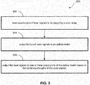
- FIG. 5 is a flow diagram of dynamic reconfiguration of an optical transmitter.
- Method 500 can be implemented using a system or apparatus described herein, or any other optical router. Although shown in a particular sequence or order, unless otherwise specified, the order of the actions can be modified. Thus, the illustrated implementations should be understood only as examples, and the illustrated method can be performed in a different order, and some actions may be performed in parallel. Additionally, one or more actions can be omitted in various embodiments of the invention; thus, not all actions are required in every implementation.
- Method 500 tunes, based on electrical signals, wavelengths of a plurality of laser signals to be output by a laser array, wherein the wavelengths of the laser signals are to determine which of one or more output ports of an optical router the laser signals are output to, 502.
- a modulator modulates the plurality of laser signals based on received electrical signals.
- the laser array outputs the plurality of laser signals to the optical router and the optical array receives the plurality of modulated laser signals, 504.
- the optical router outputs the plurality of received modulated laser signals to one or more output ports of the optical router based on the tuned wavelength of each of the plurality of received modulated laser signals, 506.
Landscapes
- Engineering & Computer Science (AREA)
- Computer Networks & Wireless Communication (AREA)
- Signal Processing (AREA)
- Physics & Mathematics (AREA)
- Electromagnetism (AREA)
- Optics & Photonics (AREA)
- Optical Communication System (AREA)
Claims (13)
- Optischer Router, umfassend:mehrere Eingangsports, wobei jeder Eingangsport dazu ausgelegt ist, ein Lasereingangssignal mit einer abstimmbaren Wellenlänge zu empfangen;mehrere Ausgangsports; undeine Steuerung, die dazu ausgelegt ist:mehrere abstimmbare Laser zu steuern, um die Wellenlängen der mehreren Lasereingangssignale abzustimmen;in einer ersten auswählbaren Konfiguration jedes der mehreren an einem entsprechenden Eingangsport empfangenen Lasereingangssignale an einen entsprechenden Ausgangsport der mehreren Ausgangsports zu leiten, um mehrere Laserausgangssignale zu bilden;in einer zweiten auswählbaren Konfiguration jedes der mehreren an einem entsprechenden Eingangsport empfangenen Lasereingangssignale an einen einzelnen Ausgangsport der mehreren Ausgangsports zu leiten, um ein einzelnes Laserausgangssignal zu bilden; und zwischen den ersten und zweiten auswählbaren Konfigurationen durch Abstimmen der Wellenlängen der mehreren abstimmbaren Laser umzuschalten.
- Optischer Router nach Anspruch 1, wobei die Steuerung die erste auswählbare Konfiguration durch Abstimmen der Wellenlängen der mehreren Lasereingangssignale so auswählt, dass sie im Wesentlichen einander gleich sind.
- Optischer Router nach Anspruch 1 oder 2, wobei die Steuerung die zweite auswählbare Konfiguration durch Abstimmen der Wellenlängen der mehreren Lasereingangssignale so auswählt, dass sie voneinander verschieden sind.
- Optischer Router nach einem der Ansprüche 1-3, ferner umfassend:mindestens ein Element, das dazu ausgelegt ist, zu erkennen, ob mindestens zwei erste Lasereingangssignale der mehreren Lasereingangssignale eine gleiche erste Wellenlänge aufweisen; undmindestens ein Element, das dazu ausgelegt ist, zu erkennen, ob mindestens zwei zweite Lasereingangssignale der mehreren Lasereingangssignale eine gleiche zweite Wellenlänge aufweisen;wobei als Reaktion auf das Erkennen, dass die mindestens zwei ersten Lasereingangssignale der mehreren Lasereingangssignale die gleiche erste Wellenlänge aufweisen, und die mindestens zwei zweiten Lasereingangssignale der mehreren Lasereingangssignale die gleiche zweite Wellenlänge aufweisen, die Steuerung ferner dazu ausgelegt ist, in einer dritten wählbaren Konfiguration:eines der ersten Lasereingangssignale und eines der zweiten Lasereingangssignale in einen ersten Ausgangsport der mehreren Ausgangsports zu leiten, um ein erstes Laserausgangssignal zu bilden; undein anderes der ersten Lasereingangssignale und ein anderes der zweiten Lasereingangssignale in einen zweiten Ausgangsports der mehreren Ausgangsports zu leiten, um ein zweites Laserausgangssignal zu bilden.
- Optischer Router nach Anspruch 4, wobei das erste und das zweite Laserausgangssignal jeweils die erste und die zweite Wellenlänge beinhalten.
- Optischer Router nach einem der Ansprüche 1-5, der ferner einen Temperatursensor umfasst, der dazu ausgelegt ist, eine Temperatur des optischen Routers zu erkennen, wobei die Steuerung ferner dazu ausgelegt ist, Daten bezüglich der erkannten Temperatur von dem Temperatursensor zu empfangen und die Wellenlängen der Lasereingangssignale als Reaktion auf die erkannte Temperatur abzustimmen.
- Optischer Router nach einem der Ansprüche 1 bis 6, ferner umfassend einen Buswellenleiter, und wobei:jeder der mehreren Eingangsports einen Eingangswellenleiter umfasst, der über einen entsprechenden Eingangsringresonator mit dem Buswellenleiter gekoppelt ist;jeder der mehreren Ausgangsports einen Ausgangswellenleiter umfasst, der über mehrere Ausgangsringresonatoren mit dem Buswellenleiter gekoppelt ist;jeder Ausgangsringresonator in jedem der mehreren Ausgangsringresonatoren dazu ausgelegt ist, Licht von dem jeweiligen Ausgangswellenleiter in den Buswellenleiter bei unterschiedlichen Wellenlängen von anderen Ausgangsringresonatoren in den jeweiligen mehreren einzukoppeln.
- Optischer Router nach Anspruch 7, wobei die Steuerung ferner dazu ausgelegt ist, die Wellenlängen der mehreren abstimmbaren Laser so abzustimmen, dass ein Koppeln zwischen einem der mehreren Ausgangsringresonatoren und dem Buswellenleiter eines der mehreren Lasereingangssignale auf mindestens zwei Ausgangsports der mehreren Ausgangsports aufteilt.
- Optischer Router nach einem der Ansprüche 1-8, ferner umfassend mindestens einen Modulator, der dazu ausgelegt ist, die mehreren Lasereingangssignale als Reaktion auf mindestens ein elektrisches Signal zu modulieren.
- Verfahren zum Routen von optischen Signalen von mehreren Eingangsports eines optischen Routers zu mehreren Ausgangsports des optischen Routers, wobei das Verfahren umfasst:an jedem Eingangsport der mehreren Eingangsports, Empfangen eines Lasereingangssignals mit einer abstimmbaren Wellenlänge;mit einer Steuerung, Steuern mehrerer abstimmbarer Laser, um die Wellenlängen der mehreren Lasereingangssignale abzustimmen;mit der Steuerung in einer ersten auswählbaren Konfiguration, Leiten eines jeden der mehreren an einem entsprechenden Eingangsport empfangenen Lasereingangssignale an einen entsprechenden Ausgangsport der mehreren Ausgangsports, um mehrere Laserausgangssignale zu bilden;mit der Steuerung in einer zweiten auswählbaren Konfiguration, Leiten eines jeden der mehreren an einem entsprechenden Eingangsport empfangenen Lasereingangssignale an einen einzelnen Ausgangsport der mehreren Ausgangsports, um ein einzelnes Laserausgangssignal zu bilden; undzwischen den ersten und zweiten auswählbaren Konfigurationen durch Abstimmen der Wellenlängen, Umschalten der mehreren abstimmbaren Laser.
- Verfahren nach Anspruch 10, wobei jedes Lasereingangssignal eine abstimmbare Wellenlänge aufweist; und
das Verfahren ferner umfasst, mit der Steuerung:Steuern mehrerer abstimmbarer Laser, um die Wellenlängen der mehreren Lasereingangssignale abzustimmen;Auswählen der ersten auswählbaren Konfiguration durch Abstimmen der Wellenlängen der mehreren Lasereingangssignale, so dass sie im Wesentlichen einander gleich sind; undAuswählen der zweiten auswählbaren Konfiguration durch Abstimmen der Wellenlängen der mehreren Lasereingangssignale, so dass sie voneinander verschieden sind. - Verfahren nach Anspruch 10, ferner umfassend als Reaktion auf das Erkennen, dass mindestens zwei erste Lasereingangssignale der mehreren Lasereingangssignale eine gleiche erste Wellenlänge aufweisen, und mindestens zwei zweite Lasereingangssignale der mehreren Lasereingangssignale eine gleiche zweite Wellenlänge aufweisen, mit der Steuerung in einer dritten wählbaren Konfiguration:Leiten eines der ersten Lasereingangssignale und eines der zweiten Lasereingangssignale in einen ersten Ausgangsport der mehreren Ausgangsports, um ein erstes Laserausgangssignal zu bilden;Leiten eines anderen der ersten Lasereingangssignale und ein anderes der zweiten Lasereingangssignale in einen zweiten Ausgangsport der mehreren Ausgangsports, um ein zweites Laserausgangssignal zu bilden, wobei das erste und das zweite Laserausgangssignal beide die ersten und zweiten Wellenlängen beinhalten;mit einem Temperatursensor, Erkennen einer Temperatur des optischen Routers; undmit der Steuerung, Empfangen von Daten in Bezug auf die erkannte Temperatur vom Temperatursensor und Abstimmen der Wellenlängen der Lasereingangssignale als Reaktion auf die erkannte Temperatur.
- Verfahren nach einem der Ansprüche 10-12, ferner umfassend:an jedem der mehreren Eingangsports, Koppeln eines entsprechenden Eingangswellenleiters über einen entsprechenden Eingangsringresonator mit dem Buswellenleiter;an jedem der mehreren Ausgangsports, Koppeln eines entsprechenden Ausgangswellenleiter, der über mehrere Ausgangsringresonatoren mit dem Buswellenleiter gekoppelt ist;an jedem der Ausgangsringresonatoren in jedem der mehreren Ausgangsringresonatoren, Einkoppeln von Licht von dem jeweiligen Ausgangswellenleiter in den Buswellenleiter bei unterschiedlichen Wellenlängen von anderen Ausgangsringresonatoren in die jeweiligen mehreren; undmit der Steuerung, Abstimmen der Wellenlängen der mehreren abstimmbaren Laser, so dass eine Kopplung zwischen einem der mehreren Ausgangsringresonatoren und dem Buswellenleiter eines der mehreren Lasereingangssignale auf mindestens zwei Ausgangsports der mehreren Ausgangsports aufteilt.
Priority Applications (1)
| Application Number | Priority Date | Filing Date | Title |
|---|---|---|---|
| EP21180668.2A EP3910820B1 (de) | 2012-07-26 | 2013-07-26 | Rekonfigurierbarer optischer sender |
Applications Claiming Priority (2)
| Application Number | Priority Date | Filing Date | Title |
|---|---|---|---|
| US13/559,400 US9525490B2 (en) | 2012-07-26 | 2012-07-26 | Reconfigurable optical transmitter |
| EP13003749.2A EP2690803B1 (de) | 2012-07-26 | 2013-07-26 | Rekonfigurierbarer optischer Sender |
Related Parent Applications (1)
| Application Number | Title | Priority Date | Filing Date |
|---|---|---|---|
| EP13003749.2A Division EP2690803B1 (de) | 2012-07-26 | 2013-07-26 | Rekonfigurierbarer optischer Sender |
Related Child Applications (1)
| Application Number | Title | Priority Date | Filing Date |
|---|---|---|---|
| EP21180668.2A Division EP3910820B1 (de) | 2012-07-26 | 2013-07-26 | Rekonfigurierbarer optischer sender |
Publications (2)
| Publication Number | Publication Date |
|---|---|
| EP3407511A1 EP3407511A1 (de) | 2018-11-28 |
| EP3407511B1 true EP3407511B1 (de) | 2021-06-23 |
Family
ID=48915797
Family Applications (3)
| Application Number | Title | Priority Date | Filing Date |
|---|---|---|---|
| EP18169429.0A Active EP3407511B1 (de) | 2012-07-26 | 2013-07-26 | Rekonfigurierbarer optischer sender |
| EP21180668.2A Active EP3910820B1 (de) | 2012-07-26 | 2013-07-26 | Rekonfigurierbarer optischer sender |
| EP13003749.2A Active EP2690803B1 (de) | 2012-07-26 | 2013-07-26 | Rekonfigurierbarer optischer Sender |
Family Applications After (2)
| Application Number | Title | Priority Date | Filing Date |
|---|---|---|---|
| EP21180668.2A Active EP3910820B1 (de) | 2012-07-26 | 2013-07-26 | Rekonfigurierbarer optischer sender |
| EP13003749.2A Active EP2690803B1 (de) | 2012-07-26 | 2013-07-26 | Rekonfigurierbarer optischer Sender |
Country Status (2)
| Country | Link |
|---|---|
| US (5) | US9525490B2 (de) |
| EP (3) | EP3407511B1 (de) |
Families Citing this family (17)
| Publication number | Priority date | Publication date | Assignee | Title |
|---|---|---|---|---|
| US9379838B2 (en) * | 2011-12-30 | 2016-06-28 | Infinera Corporation | Optical communication system having tunable sources |
| US9525490B2 (en) * | 2012-07-26 | 2016-12-20 | Aurrion, Inc. | Reconfigurable optical transmitter |
| US9207399B2 (en) | 2013-01-28 | 2015-12-08 | Aurrion, Inc. | Athermal optical filter with active tuning and simplified control |
| WO2016148717A1 (en) * | 2015-03-19 | 2016-09-22 | Hewlett Packard Enterprise Development Lp | Transceiver nodes coupled to arrayed waveguide gratings |
| EP3929654B1 (de) | 2015-07-24 | 2025-06-18 | OpenLight Photonics, Inc. | Phasenabstimmung in wellenleiter-arrays |
| US10820071B2 (en) | 2015-08-13 | 2020-10-27 | Hewlett Packard Enterprise Development Lp | Reconfigurable interconnected nodes |
| EP3272041B1 (de) | 2015-08-13 | 2019-12-04 | Hewlett-Packard Enterprise Development LP | Rekonfigurierbare verbundene knoten |
| US10171171B2 (en) * | 2016-07-07 | 2019-01-01 | Luxtera, Inc. | Method and system for selectable parallel optical fiber and wavelength division multiplexed operation |
| US10771160B2 (en) | 2016-07-14 | 2020-09-08 | Ayar Labs, Inc. | Laser module for optical data communication system |
| KR20190133792A (ko) * | 2017-06-07 | 2019-12-03 | 투-식스 델라웨어, 인코포레이티드 | 통합 wdm 광 송수신기 |
| TW202549291A (zh) * | 2017-11-21 | 2025-12-16 | 美商爾雅實驗室公司 | 多晶片模組 |
| US10999654B2 (en) * | 2019-07-10 | 2021-05-04 | Cisco Technology, Inc. | Multiple port network device with differential ports for reduced electromagnetic interference at optical modules |
| US11029476B2 (en) | 2019-09-25 | 2021-06-08 | Hewlett Packard Enterprise Development Lp | Injection locked multi-wavelength optical source |
| US11487181B2 (en) | 2020-06-30 | 2022-11-01 | Hewlett Packard Enterprise Development Lp | Low drive voltage multi-wavelength transmitter |
| US11539440B2 (en) | 2020-07-16 | 2022-12-27 | Hewlett Packard Enterprise Development Lp | Injection seeding of a comb laser |
| US12549259B2 (en) * | 2022-01-18 | 2026-02-10 | Quintessent Inc. | Photonic integrated circuit for high-wavelength-channel-count wavelength-division-multiplexed systems |
| US12526055B2 (en) | 2022-06-29 | 2026-01-13 | Quintessent Inc. | Photonic integrated circuit for high-wavelength-channel-count wavelength-division-multiplexed systems |
Family Cites Families (81)
| Publication number | Priority date | Publication date | Assignee | Title |
|---|---|---|---|---|
| US5002350A (en) | 1990-02-26 | 1991-03-26 | At&T Bell Laboratories | Optical multiplexer/demultiplexer |
| US5455699A (en) * | 1993-12-21 | 1995-10-03 | At&T Corp. | Large capacity multi-access wavelength division multiplexing packet network |
| US5550666A (en) | 1994-06-17 | 1996-08-27 | Lucent Technologies Inc. | Wavelength division multiplexed multi-frequency optical source and broadband incoherent optical source |
| US5617234A (en) * | 1994-09-26 | 1997-04-01 | Nippon Telegraph & Telephone Corporation | Multiwavelength simultaneous monitoring circuit employing arrayed-waveguide grating |
| US5515460A (en) | 1994-12-22 | 1996-05-07 | At&T Corp. | Tunable silicon based optical router |
| US5612968A (en) | 1995-04-20 | 1997-03-18 | Bell Communications Research, Inc. | Redundant multi-wavelength laser arrays |
| US6097517A (en) * | 1995-09-01 | 2000-08-01 | Oki Electric Industry Co., Ltd. | Wavelength router |
| US5870216A (en) * | 1995-10-26 | 1999-02-09 | Trw Inc. | Splitterless optical broadcast switch |
| US5745612A (en) * | 1995-12-18 | 1998-04-28 | International Business Machines Corporation | Wavelength sorter and its application to planarized dynamic wavelength routing |
| JP3036586B2 (ja) * | 1996-05-09 | 2000-04-24 | 日本電信電話株式会社 | Atmスイッチ |
| KR100216529B1 (ko) * | 1997-05-16 | 1999-08-16 | 이계철 | 배열 도파로 격자를 이용한 파장정렬장치 |
| US6304350B1 (en) | 1997-05-27 | 2001-10-16 | Lucent Technologies Inc | Temperature compensated multi-channel, wavelength-division-multiplexed passive optical network |
| US6049640A (en) * | 1997-09-04 | 2000-04-11 | Lucent Technologies Inc. | Wavelength-division-multiplexing cross-connect using angular dispersive elements and phase shifters |
| US6058233A (en) * | 1998-06-30 | 2000-05-02 | Lucent Technologies Inc. | Waveguide array with improved efficiency for wavelength routers and star couplers in integrated optics |
| US6195187B1 (en) * | 1998-07-07 | 2001-02-27 | The United States Of America As Represented By The Secretary Of The Air Force | Wavelength-division multiplexed M×N×M cross-connect switch using active microring resonators |
| US7110669B2 (en) | 1998-07-22 | 2006-09-19 | Synchrodyne Networks, Inc. | Time driven wavelength conversion-based switching with common time reference |
| US6067389A (en) * | 1998-07-27 | 2000-05-23 | Lucent Technologies Inc. | Wavelength-selective optical cross-connect |
| JP2001085800A (ja) * | 1999-09-09 | 2001-03-30 | Hitachi Ltd | 半導体光増幅器モジュールおよび光通信システム |
| WO2001022141A1 (en) * | 1999-09-21 | 2001-03-29 | Nanovation Technologies, Inc. | Wavelength-slicing architecture for wavelength demultiplexing using micro-ring resonators |
| US6735393B1 (en) | 1999-09-24 | 2004-05-11 | Telenor, As | All-optical network with passive wavelength routers |
| US6438295B1 (en) | 1999-10-05 | 2002-08-20 | Nortel Networks Limited | Adaptive optical waveguide router |
| US6594049B1 (en) | 1999-10-29 | 2003-07-15 | Lucent Technologies Inc. | Optical router |
| TW508461B (en) * | 1999-11-23 | 2002-11-01 | Nanovation Tech Inc | Localized thermal tuning of ring resonators |
| US20030128980A1 (en) * | 2002-11-27 | 2003-07-10 | Abeles Joseph H. | Channelizer switch |
| US6519062B1 (en) * | 2000-02-29 | 2003-02-11 | The Regents Of The University Of California | Ultra-low latency multi-protocol optical routers for the next generation internet |
| JP3736303B2 (ja) | 2000-06-29 | 2006-01-18 | 日本電気株式会社 | アレイ導波路格子、マルチプレクサ装置、デマルチプレクサ装置、ノード装置および光通信システム |
| US7171117B1 (en) | 2000-08-25 | 2007-01-30 | Lucent Technologies Inc. | Optical router |
| JP2002101051A (ja) * | 2000-09-21 | 2002-04-05 | Hitachi Ltd | 波長多重光インタコネクション装置 |
| JP2002171023A (ja) * | 2000-11-30 | 2002-06-14 | Hitachi Ltd | 集積化光素子及び半導体レーザモジュール並びに光送信機 |
| US7426210B1 (en) * | 2001-04-03 | 2008-09-16 | Yt Networks Capital, Llc | Port-to-port, non-blocking, scalable optical router architecture and method for routing optical traffic |
| US7116851B2 (en) * | 2001-10-09 | 2006-10-03 | Infinera Corporation | Optical signal receiver, an associated photonic integrated circuit (RxPIC), and method improving performance |
| US7672546B2 (en) * | 2001-10-09 | 2010-03-02 | Infinera Corporation | Optical transport network having a plurality of monolithic photonic integrated circuit semiconductor chips |
| US7751658B2 (en) * | 2001-10-09 | 2010-07-06 | Infinera Corporation | Monolithic transmitter photonic integrated circuit (TxPIC) having tunable modulated sources with feedback system for source power level or wavelength tuning |
| DE60208416T2 (de) | 2001-10-09 | 2006-06-22 | Infinera Corp., Sunnyvale | Digitale optische netzwerkarchitektur |
| CA2463278C (en) | 2001-10-09 | 2013-04-02 | Infinera Corporation | Transmitter photonic integrated circuits (txpic) and optical transport networks employing txpics |
| US7062111B2 (en) * | 2001-11-06 | 2006-06-13 | Grubb Stephen G | Optical communication module with one or more photonic integrated circuit (PIC) chips and an external booster optical amplifier for photonic integrated circuits (PICs) |
| US6597841B1 (en) | 2002-01-14 | 2003-07-22 | Corning Incorporated | Multi-output arrayed waveguide grating demultiplexer |
| US6731425B1 (en) | 2002-03-07 | 2004-05-04 | Cisco Technology, Inc. | Modular Raman pump double-multiplexer |
| US7006719B2 (en) * | 2002-03-08 | 2006-02-28 | Infinera Corporation | In-wafer testing of integrated optical components in photonic integrated circuits (PICs) |
| US7801446B2 (en) * | 2002-06-14 | 2010-09-21 | Infinera Corporation | Wavelength division multiplexed optical communication system with rapidly-tunable optical filters |
| US7747114B2 (en) * | 2002-10-08 | 2010-06-29 | Infinera Corporation | Tilted combiners/decombiners and photonic integrated circuits (PICs) employing the same |
| US6940863B2 (en) * | 2003-01-13 | 2005-09-06 | The Regents Of The University Of California | Edge router for optical label switched network |
| US7245829B1 (en) * | 2004-01-12 | 2007-07-17 | Nortel Networks Limited | Architecture for dynamic connectivity in an edge photonic network architecture |
| US7636522B2 (en) * | 2004-04-15 | 2009-12-22 | Infinera Corporation | Coolerless photonic integrated circuits (PICs) for WDM transmission networks and PICs operable with a floating signal channel grid changing with temperature but with fixed channel spacing in the floating grid |
| KR20050120474A (ko) * | 2004-06-19 | 2005-12-22 | 삼성전자주식회사 | 전자렌지 |
| US8032027B2 (en) * | 2005-07-25 | 2011-10-04 | Massachusetts Institute Of Technology | Wide free-spectral-range, widely tunable and hitless-switchable optical channel add-drop filters |
| US7831146B2 (en) * | 2005-09-15 | 2010-11-09 | Mazed Mohammad A | Time and wavelength-shifted dynamic bidirectional system |
| US7869711B2 (en) * | 2005-10-18 | 2011-01-11 | Nec Laboratories America, Inc. | Optical tunable asymmetric interleaver and upgrade for dense wavelength division multiplexed networks |
| US8285150B2 (en) * | 2006-10-02 | 2012-10-09 | Futurewei Technologies, Inc. | Method and system for integrated DWDM transmitters |
| US8285151B2 (en) * | 2006-10-20 | 2012-10-09 | Futurewei Technologies, Inc. | Method and system for hybrid integrated 1XN DWDM transmitter |
| US8315522B2 (en) * | 2006-11-30 | 2012-11-20 | Nec Corporation | Wavelength routing system |
| JP4796183B2 (ja) * | 2007-03-16 | 2011-10-19 | 富士通株式会社 | 光伝送装置 |
| US8073342B2 (en) * | 2007-05-04 | 2011-12-06 | Massachusetts Institute Of Technology | Method and apparatus for transmitting optical signals |
| US8965220B2 (en) * | 2007-05-30 | 2015-02-24 | Tellabs Operations, Inc. | Reconfigurable optical add/drop multiplexer and procedure for outputting optical signals from such multiplexer |
| US7548668B2 (en) * | 2007-11-21 | 2009-06-16 | Alcatel-Lucent Usa Inc. | Programmable optical array |
| US8320759B2 (en) * | 2008-03-05 | 2012-11-27 | Tellabs Operations, Inc. | Methods and apparatus for reconfigurable add drop multiplexers |
| US8260150B2 (en) | 2008-04-25 | 2012-09-04 | Finisar Corporation | Passive wave division multiplexed transmitter having a directly modulated laser array |
| US8837950B2 (en) * | 2008-08-28 | 2014-09-16 | Finisar Corporation | Accessing transceiver link information from host interface |
| WO2010032844A1 (ja) * | 2008-09-19 | 2010-03-25 | 日本電信電話株式会社 | 帯域可変通信装置及び帯域可変通信方法 |
| EP2270478B1 (de) * | 2009-07-01 | 2012-03-28 | Fraunhofer-Gesellschaft zur Förderung der angewandten Forschung e.V. | Optischer Sensor und Verfahren zum Detektieren von Molekülen |
| US8295712B2 (en) | 2009-09-14 | 2012-10-23 | Alcatel Lucent | Optical device and method for optical frequency modulation to optical amplitude modulation conversion |
| US8964581B2 (en) * | 2009-09-14 | 2015-02-24 | Nippon Telegraph And Telephone Corporation | Bandwidth variable communication method, bandwidth variable communication apparatus, transmission bandwidth determination apparatus, transmission bandwidth determination method, node apparatus, communication path setting system, communication path setting |
| US8705972B2 (en) * | 2010-05-11 | 2014-04-22 | Hewlett-Packard Development Company, L.P. | Energy-efficient and fault-tolerant resonator-based modulation and wavelength division multiplexing systems |
| US8472805B2 (en) * | 2010-05-26 | 2013-06-25 | Google Inc. | Tunable multi-wavelength optical transmitter and transceiver for optical communications based on wavelength division multiplexing |
| US9634792B2 (en) * | 2010-11-24 | 2017-04-25 | Alcatel Lucent | Method and apparatus of performing ONT wavelength tuning via a heat source |
| JP5807338B2 (ja) * | 2011-02-14 | 2015-11-10 | 富士通株式会社 | 光伝送装置および光フィルタ回路 |
| US8594471B2 (en) * | 2011-03-30 | 2013-11-26 | Telefonaktiebolaget L M Ericsson (Publ) | Adaptive waveguide optical switching system and method |
| US9124371B2 (en) * | 2011-04-01 | 2015-09-01 | Infinera Corporation | Apparatus to control carrier spacing in a multi-carrier optical transmitter |
| WO2012147889A1 (ja) * | 2011-04-27 | 2012-11-01 | 日本電信電話株式会社 | 光通信装置及び光経路切替装置及びネットワーク |
| JP5824912B2 (ja) * | 2011-06-29 | 2015-12-02 | 富士通株式会社 | 光伝送装置および光インターリーブ制御方法 |
| US8899937B2 (en) * | 2011-07-11 | 2014-12-02 | Building Turbines, Inc. | Excessive wind portal for wind turbines |
| US9160455B2 (en) * | 2011-07-14 | 2015-10-13 | Applied Optoelectronics, Inc. | External cavity laser array system and WDM optical system including same |
| US20130016971A1 (en) * | 2011-07-14 | 2013-01-17 | Applied Optoelectronics, Inc. | Wdm optical system and method including multi-channel transmitters with filtered output for channel wavelength selection |
| US9379838B2 (en) * | 2011-12-30 | 2016-06-28 | Infinera Corporation | Optical communication system having tunable sources |
| US9341774B2 (en) * | 2012-01-24 | 2016-05-17 | Applied Optoelectronics, Inc. | Optically matched laser array coupling assembly for coupling laser array to arrayed waveguide grating |
| US8737846B2 (en) * | 2012-01-30 | 2014-05-27 | Oracle International Corporation | Dynamic-grid comb optical source |
| US8885996B2 (en) * | 2012-07-17 | 2014-11-11 | Oracle International Corporation | Optical device with a CMOS-compatible echelle grating |
| US9525490B2 (en) | 2012-07-26 | 2016-12-20 | Aurrion, Inc. | Reconfigurable optical transmitter |
| US9285538B2 (en) * | 2012-10-23 | 2016-03-15 | Lumentum Operations Llc | Reducing temperature drift of an arrayed waveguide grating |
| US9559801B2 (en) * | 2013-04-26 | 2017-01-31 | Tyco Electronics Subsea Communications Llc | System and method for applying system policies in an optical communication system having user-allocated bandwidth |
| CN103543497B (zh) * | 2013-11-05 | 2016-08-24 | 武汉邮电科学研究院 | 波长选择开关装置、用于其的波长切换方法、和通信设备 |
-
2012
- 2012-07-26 US US13/559,400 patent/US9525490B2/en active Active
-
2013
- 2013-07-26 EP EP18169429.0A patent/EP3407511B1/de active Active
- 2013-07-26 EP EP21180668.2A patent/EP3910820B1/de active Active
- 2013-07-26 EP EP13003749.2A patent/EP2690803B1/de active Active
-
2016
- 2016-12-12 US US15/375,532 patent/US10320515B1/en active Active
-
2019
- 2019-05-03 US US16/402,970 patent/US10826643B2/en active Active
-
2020
- 2020-10-07 US US17/065,146 patent/US11356191B2/en active Active
-
2022
- 2022-05-04 US US17/736,506 patent/US11909516B2/en active Active
Also Published As
| Publication number | Publication date |
|---|---|
| US20140328591A1 (en) | 2014-11-06 |
| US11356191B2 (en) | 2022-06-07 |
| US20220263595A1 (en) | 2022-08-18 |
| US10826643B2 (en) | 2020-11-03 |
| EP3910820B1 (de) | 2025-04-16 |
| EP2690803B1 (de) | 2018-05-16 |
| US20210021367A1 (en) | 2021-01-21 |
| EP3407511A1 (de) | 2018-11-28 |
| US20190260492A1 (en) | 2019-08-22 |
| EP3910820A1 (de) | 2021-11-17 |
| US10320515B1 (en) | 2019-06-11 |
| EP2690803A1 (de) | 2014-01-29 |
| US9525490B2 (en) | 2016-12-20 |
| US11909516B2 (en) | 2024-02-20 |
Similar Documents
| Publication | Publication Date | Title |
|---|---|---|
| US11909516B2 (en) | Reconfigurable optical router | |
| US5557439A (en) | Expandable wavelength division multiplexed optical communications systems | |
| CN107636988B (zh) | 具有改进的光放大的、基于wdm梳状源的光链路 | |
| US5173794A (en) | Wavelength division multiplexing using a tunable acousto-optic filter | |
| EP0699927B1 (de) | Abstimmbare optische Einfüge-/Abzweigmethode und -apparat | |
| KR100380924B1 (ko) | 광 전송 관련 장치 및 방법 | |
| US9379838B2 (en) | Optical communication system having tunable sources | |
| CN111181653A (zh) | 波分复用偏振无关反射调制器 | |
| US6549313B1 (en) | Broadbrand electronic N×N cross-connect switch using tunable lasers | |
| WO2022267547A1 (zh) | 一种业务光信号的传输方法、网络设备以及光网络 | |
| US9419742B2 (en) | Optical communication system having tunable sources | |
| CN113872698B (zh) | 低驱动电压多波长发射器及光学系统 | |
| EP1356620B1 (de) | Optisches wdm-kommunikationssystem | |
| US12328182B2 (en) | Optical devices for coarse wavelength division multiplexing wavebands | |
| Testa et al. | Silicon photonics for telecom and datacom applications | |
| TW202225750A (zh) | 光學數據通訊系統及相關方法 | |
| EP3272041B1 (de) | Rekonfigurierbare verbundene knoten | |
| JP4230934B2 (ja) | 多チャンネル光変調装置および多チャンネル光送信装置 | |
| WO2022267542A1 (zh) | 一种业务光信号的传输方法、网络设备以及光网络 | |
| JP2020072351A (ja) | 光伝送装置及び光素子 | |
| US20200100002A1 (en) | Reconfigurable interconnected nodes | |
| JP2009284333A (ja) | 波長多重光送信器 |
Legal Events
| Date | Code | Title | Description |
|---|---|---|---|
| PUAI | Public reference made under article 153(3) epc to a published international application that has entered the european phase |
Free format text: ORIGINAL CODE: 0009012 |
|
| STAA | Information on the status of an ep patent application or granted ep patent |
Free format text: STATUS: THE APPLICATION HAS BEEN PUBLISHED |
|
| AC | Divisional application: reference to earlier application |
Ref document number: 2690803 Country of ref document: EP Kind code of ref document: P |
|
| AK | Designated contracting states |
Kind code of ref document: A1 Designated state(s): AL AT BE BG CH CY CZ DE DK EE ES FI FR GB GR HR HU IE IS IT LI LT LU LV MC MK MT NL NO PL PT RO RS SE SI SK SM TR |
|
| STAA | Information on the status of an ep patent application or granted ep patent |
Free format text: STATUS: REQUEST FOR EXAMINATION WAS MADE |
|
| 17P | Request for examination filed |
Effective date: 20190528 |
|
| RBV | Designated contracting states (corrected) |
Designated state(s): AL AT BE BG CH CY CZ DE DK EE ES FI FR GB GR HR HU IE IS IT LI LT LU LV MC MK MT NL NO PL PT RO RS SE SI SK SM TR |
|
| GRAP | Despatch of communication of intention to grant a patent |
Free format text: ORIGINAL CODE: EPIDOSNIGR1 |
|
| STAA | Information on the status of an ep patent application or granted ep patent |
Free format text: STATUS: GRANT OF PATENT IS INTENDED |
|
| RIC1 | Information provided on ipc code assigned before grant |
Ipc: H04J 14/02 20060101ALI20201204BHEP Ipc: H04B 10/564 20130101ALI20201204BHEP Ipc: H04Q 11/00 20060101ALI20201204BHEP Ipc: H04J 14/00 20060101ALI20201204BHEP Ipc: H04B 10/50 20130101AFI20201204BHEP |
|
| RAP1 | Party data changed (applicant data changed or rights of an application transferred) |
Owner name: AURRION, INC. |
|
| INTG | Intention to grant announced |
Effective date: 20210113 |
|
| GRAS | Grant fee paid |
Free format text: ORIGINAL CODE: EPIDOSNIGR3 |
|
| GRAA | (expected) grant |
Free format text: ORIGINAL CODE: 0009210 |
|
| STAA | Information on the status of an ep patent application or granted ep patent |
Free format text: STATUS: THE PATENT HAS BEEN GRANTED |
|
| AC | Divisional application: reference to earlier application |
Ref document number: 2690803 Country of ref document: EP Kind code of ref document: P |
|
| AK | Designated contracting states |
Kind code of ref document: B1 Designated state(s): AL AT BE BG CH CY CZ DE DK EE ES FI FR GB GR HR HU IE IS IT LI LT LU LV MC MK MT NL NO PL PT RO RS SE SI SK SM TR |
|
| REG | Reference to a national code |
Ref country code: GB Ref legal event code: FG4D |
|
| REG | Reference to a national code |
Ref country code: CH Ref legal event code: EP |
|
| REG | Reference to a national code |
Ref country code: DE Ref legal event code: R096 Ref document number: 602013078097 Country of ref document: DE Ref country code: AT Ref legal event code: REF Ref document number: 1405229 Country of ref document: AT Kind code of ref document: T Effective date: 20210715 |
|
| REG | Reference to a national code |
Ref country code: IE Ref legal event code: FG4D |
|
| REG | Reference to a national code |
Ref country code: LT Ref legal event code: MG9D |
|
| PG25 | Lapsed in a contracting state [announced via postgrant information from national office to epo] |
Ref country code: BG Free format text: LAPSE BECAUSE OF FAILURE TO SUBMIT A TRANSLATION OF THE DESCRIPTION OR TO PAY THE FEE WITHIN THE PRESCRIBED TIME-LIMIT Effective date: 20210923 Ref country code: LT Free format text: LAPSE BECAUSE OF FAILURE TO SUBMIT A TRANSLATION OF THE DESCRIPTION OR TO PAY THE FEE WITHIN THE PRESCRIBED TIME-LIMIT Effective date: 20210623 Ref country code: HR Free format text: LAPSE BECAUSE OF FAILURE TO SUBMIT A TRANSLATION OF THE DESCRIPTION OR TO PAY THE FEE WITHIN THE PRESCRIBED TIME-LIMIT Effective date: 20210623 Ref country code: FI Free format text: LAPSE BECAUSE OF FAILURE TO SUBMIT A TRANSLATION OF THE DESCRIPTION OR TO PAY THE FEE WITHIN THE PRESCRIBED TIME-LIMIT Effective date: 20210623 |
|
| REG | Reference to a national code |
Ref country code: AT Ref legal event code: MK05 Ref document number: 1405229 Country of ref document: AT Kind code of ref document: T Effective date: 20210623 |
|
| PG25 | Lapsed in a contracting state [announced via postgrant information from national office to epo] |
Ref country code: GR Free format text: LAPSE BECAUSE OF FAILURE TO SUBMIT A TRANSLATION OF THE DESCRIPTION OR TO PAY THE FEE WITHIN THE PRESCRIBED TIME-LIMIT Effective date: 20210924 Ref country code: LV Free format text: LAPSE BECAUSE OF FAILURE TO SUBMIT A TRANSLATION OF THE DESCRIPTION OR TO PAY THE FEE WITHIN THE PRESCRIBED TIME-LIMIT Effective date: 20210623 Ref country code: NO Free format text: LAPSE BECAUSE OF FAILURE TO SUBMIT A TRANSLATION OF THE DESCRIPTION OR TO PAY THE FEE WITHIN THE PRESCRIBED TIME-LIMIT Effective date: 20210923 Ref country code: SE Free format text: LAPSE BECAUSE OF FAILURE TO SUBMIT A TRANSLATION OF THE DESCRIPTION OR TO PAY THE FEE WITHIN THE PRESCRIBED TIME-LIMIT Effective date: 20210623 Ref country code: RS Free format text: LAPSE BECAUSE OF FAILURE TO SUBMIT A TRANSLATION OF THE DESCRIPTION OR TO PAY THE FEE WITHIN THE PRESCRIBED TIME-LIMIT Effective date: 20210623 |
|
| REG | Reference to a national code |
Ref country code: NL Ref legal event code: MP Effective date: 20210623 |
|
| PG25 | Lapsed in a contracting state [announced via postgrant information from national office to epo] |
Ref country code: RO Free format text: LAPSE BECAUSE OF FAILURE TO SUBMIT A TRANSLATION OF THE DESCRIPTION OR TO PAY THE FEE WITHIN THE PRESCRIBED TIME-LIMIT Effective date: 20210623 Ref country code: PT Free format text: LAPSE BECAUSE OF FAILURE TO SUBMIT A TRANSLATION OF THE DESCRIPTION OR TO PAY THE FEE WITHIN THE PRESCRIBED TIME-LIMIT Effective date: 20211025 Ref country code: NL Free format text: LAPSE BECAUSE OF FAILURE TO SUBMIT A TRANSLATION OF THE DESCRIPTION OR TO PAY THE FEE WITHIN THE PRESCRIBED TIME-LIMIT Effective date: 20210623 Ref country code: AT Free format text: LAPSE BECAUSE OF FAILURE TO SUBMIT A TRANSLATION OF THE DESCRIPTION OR TO PAY THE FEE WITHIN THE PRESCRIBED TIME-LIMIT Effective date: 20210623 Ref country code: CZ Free format text: LAPSE BECAUSE OF FAILURE TO SUBMIT A TRANSLATION OF THE DESCRIPTION OR TO PAY THE FEE WITHIN THE PRESCRIBED TIME-LIMIT Effective date: 20210623 Ref country code: SM Free format text: LAPSE BECAUSE OF FAILURE TO SUBMIT A TRANSLATION OF THE DESCRIPTION OR TO PAY THE FEE WITHIN THE PRESCRIBED TIME-LIMIT Effective date: 20210623 Ref country code: SK Free format text: LAPSE BECAUSE OF FAILURE TO SUBMIT A TRANSLATION OF THE DESCRIPTION OR TO PAY THE FEE WITHIN THE PRESCRIBED TIME-LIMIT Effective date: 20210623 Ref country code: EE Free format text: LAPSE BECAUSE OF FAILURE TO SUBMIT A TRANSLATION OF THE DESCRIPTION OR TO PAY THE FEE WITHIN THE PRESCRIBED TIME-LIMIT Effective date: 20210623 Ref country code: ES Free format text: LAPSE BECAUSE OF FAILURE TO SUBMIT A TRANSLATION OF THE DESCRIPTION OR TO PAY THE FEE WITHIN THE PRESCRIBED TIME-LIMIT Effective date: 20210623 |
|
| PG25 | Lapsed in a contracting state [announced via postgrant information from national office to epo] |
Ref country code: PL Free format text: LAPSE BECAUSE OF FAILURE TO SUBMIT A TRANSLATION OF THE DESCRIPTION OR TO PAY THE FEE WITHIN THE PRESCRIBED TIME-LIMIT Effective date: 20210623 |
|
| REG | Reference to a national code |
Ref country code: CH Ref legal event code: PL |
|
| REG | Reference to a national code |
Ref country code: DE Ref legal event code: R097 Ref document number: 602013078097 Country of ref document: DE |
|
| PG25 | Lapsed in a contracting state [announced via postgrant information from national office to epo] |
Ref country code: MC Free format text: LAPSE BECAUSE OF FAILURE TO SUBMIT A TRANSLATION OF THE DESCRIPTION OR TO PAY THE FEE WITHIN THE PRESCRIBED TIME-LIMIT Effective date: 20210623 |
|
| REG | Reference to a national code |
Ref country code: BE Ref legal event code: MM Effective date: 20210731 |
|
| PG25 | Lapsed in a contracting state [announced via postgrant information from national office to epo] |
Ref country code: LI Free format text: LAPSE BECAUSE OF NON-PAYMENT OF DUE FEES Effective date: 20210731 Ref country code: DK Free format text: LAPSE BECAUSE OF FAILURE TO SUBMIT A TRANSLATION OF THE DESCRIPTION OR TO PAY THE FEE WITHIN THE PRESCRIBED TIME-LIMIT Effective date: 20210623 Ref country code: CH Free format text: LAPSE BECAUSE OF NON-PAYMENT OF DUE FEES Effective date: 20210731 |
|
| PLBE | No opposition filed within time limit |
Free format text: ORIGINAL CODE: 0009261 |
|
| STAA | Information on the status of an ep patent application or granted ep patent |
Free format text: STATUS: NO OPPOSITION FILED WITHIN TIME LIMIT |
|
| 26N | No opposition filed |
Effective date: 20220324 |
|
| PG25 | Lapsed in a contracting state [announced via postgrant information from national office to epo] |
Ref country code: LU Free format text: LAPSE BECAUSE OF NON-PAYMENT OF DUE FEES Effective date: 20210726 Ref country code: AL Free format text: LAPSE BECAUSE OF FAILURE TO SUBMIT A TRANSLATION OF THE DESCRIPTION OR TO PAY THE FEE WITHIN THE PRESCRIBED TIME-LIMIT Effective date: 20210623 |
|
| REG | Reference to a national code |
Ref country code: DE Ref legal event code: R081 Ref document number: 602013078097 Country of ref document: DE Owner name: JUNIPER NETWORKS, INC., SUNNYVALE, US Free format text: FORMER OWNER: AURRION, INC., GOLETA, CALIF., US |
|
| REG | Reference to a national code |
Ref country code: GB Ref legal event code: 732E Free format text: REGISTERED BETWEEN 20220606 AND 20220608 |
|
| PG25 | Lapsed in a contracting state [announced via postgrant information from national office to epo] |
Ref country code: IT Free format text: LAPSE BECAUSE OF FAILURE TO SUBMIT A TRANSLATION OF THE DESCRIPTION OR TO PAY THE FEE WITHIN THE PRESCRIBED TIME-LIMIT Effective date: 20210623 Ref country code: IE Free format text: LAPSE BECAUSE OF NON-PAYMENT OF DUE FEES Effective date: 20210726 Ref country code: BE Free format text: LAPSE BECAUSE OF NON-PAYMENT OF DUE FEES Effective date: 20210731 |
|
| P01 | Opt-out of the competence of the unified patent court (upc) registered |
Effective date: 20230520 |
|
| PG25 | Lapsed in a contracting state [announced via postgrant information from national office to epo] |
Ref country code: CY Free format text: LAPSE BECAUSE OF FAILURE TO SUBMIT A TRANSLATION OF THE DESCRIPTION OR TO PAY THE FEE WITHIN THE PRESCRIBED TIME-LIMIT Effective date: 20210623 |
|
| PG25 | Lapsed in a contracting state [announced via postgrant information from national office to epo] |
Ref country code: HU Free format text: LAPSE BECAUSE OF FAILURE TO SUBMIT A TRANSLATION OF THE DESCRIPTION OR TO PAY THE FEE WITHIN THE PRESCRIBED TIME-LIMIT; INVALID AB INITIO Effective date: 20130726 |
|
| PG25 | Lapsed in a contracting state [announced via postgrant information from national office to epo] |
Ref country code: MK Free format text: LAPSE BECAUSE OF FAILURE TO SUBMIT A TRANSLATION OF THE DESCRIPTION OR TO PAY THE FEE WITHIN THE PRESCRIBED TIME-LIMIT Effective date: 20210623 |
|
| PG25 | Lapsed in a contracting state [announced via postgrant information from national office to epo] |
Ref country code: MT Free format text: LAPSE BECAUSE OF FAILURE TO SUBMIT A TRANSLATION OF THE DESCRIPTION OR TO PAY THE FEE WITHIN THE PRESCRIBED TIME-LIMIT Effective date: 20210623 |
|
| PGFP | Annual fee paid to national office [announced via postgrant information from national office to epo] |
Ref country code: GB Payment date: 20250619 Year of fee payment: 13 |
|
| PGFP | Annual fee paid to national office [announced via postgrant information from national office to epo] |
Ref country code: DE Payment date: 20250620 Year of fee payment: 13 |
|
| PG25 | Lapsed in a contracting state [announced via postgrant information from national office to epo] |
Ref country code: TR Free format text: LAPSE BECAUSE OF FAILURE TO SUBMIT A TRANSLATION OF THE DESCRIPTION OR TO PAY THE FEE WITHIN THE PRESCRIBED TIME-LIMIT Effective date: 20210623 |
|
| PGFP | Annual fee paid to national office [announced via postgrant information from national office to epo] |
Ref country code: FR Payment date: 20260325 Year of fee payment: 14 |