EP3408035B1 - Système de distribution de colle - Google Patents
Système de distribution de colle Download PDFInfo
- Publication number
- EP3408035B1 EP3408035B1 EP16888531.7A EP16888531A EP3408035B1 EP 3408035 B1 EP3408035 B1 EP 3408035B1 EP 16888531 A EP16888531 A EP 16888531A EP 3408035 B1 EP3408035 B1 EP 3408035B1
- Authority
- EP
- European Patent Office
- Prior art keywords
- glue
- moving substrate
- delivery system
- motor shaft
- gear
- Prior art date
- Legal status (The legal status is an assumption and is not a legal conclusion. Google has not performed a legal analysis and makes no representation as to the accuracy of the status listed.)
- Active
Links
Images



Classifications
-
- B—PERFORMING OPERATIONS; TRANSPORTING
- B29—WORKING OF PLASTICS; WORKING OF SUBSTANCES IN A PLASTIC STATE IN GENERAL
- B29C—SHAPING OR JOINING OF PLASTICS; SHAPING OF MATERIAL IN A PLASTIC STATE, NOT OTHERWISE PROVIDED FOR; AFTER-TREATMENT OF THE SHAPED PRODUCTS, e.g. REPAIRING
- B29C65/00—Joining or sealing of preformed parts, e.g. welding of plastics materials; Apparatus therefor
- B29C65/48—Joining or sealing of preformed parts, e.g. welding of plastics materials; Apparatus therefor using adhesives, i.e. using supplementary joining material; solvent bonding
- B29C65/52—Joining or sealing of preformed parts, e.g. welding of plastics materials; Apparatus therefor using adhesives, i.e. using supplementary joining material; solvent bonding characterised by the way of applying the adhesive
- B29C65/524—Joining or sealing of preformed parts, e.g. welding of plastics materials; Apparatus therefor using adhesives, i.e. using supplementary joining material; solvent bonding characterised by the way of applying the adhesive by applying the adhesive from an outlet device in contact with, or almost in contact with, the surface of the part to be joined
- B29C65/525—Joining or sealing of preformed parts, e.g. welding of plastics materials; Apparatus therefor using adhesives, i.e. using supplementary joining material; solvent bonding characterised by the way of applying the adhesive by applying the adhesive from an outlet device in contact with, or almost in contact with, the surface of the part to be joined by extrusion coating
-
- B—PERFORMING OPERATIONS; TRANSPORTING
- B05—SPRAYING OR ATOMISING IN GENERAL; APPLYING FLUENT MATERIALS TO SURFACES, IN GENERAL
- B05C—APPARATUS FOR APPLYING FLUENT MATERIALS TO SURFACES, IN GENERAL
- B05C5/00—Apparatus in which liquid or other fluent material is projected, poured or allowed to flow on to the surface of the work
- B05C5/02—Apparatus in which liquid or other fluent material is projected, poured or allowed to flow on to the surface of the work the liquid or other fluent material being discharged through an outlet orifice by pressure, e.g. from an outlet device in contact or almost in contact, with the work
- B05C5/027—Coating heads with several outlets, e.g. aligned transversally to the moving direction of a web to be coated
- B05C5/0275—Coating heads with several outlets, e.g. aligned transversally to the moving direction of a web to be coated flow controlled, e.g. by a valve
- B05C5/0279—Coating heads with several outlets, e.g. aligned transversally to the moving direction of a web to be coated flow controlled, e.g. by a valve independently, e.g. individually, flow controlled
-
- B—PERFORMING OPERATIONS; TRANSPORTING
- B05—SPRAYING OR ATOMISING IN GENERAL; APPLYING FLUENT MATERIALS TO SURFACES, IN GENERAL
- B05C—APPARATUS FOR APPLYING FLUENT MATERIALS TO SURFACES, IN GENERAL
- B05C9/00—Apparatus or plant for applying liquid or other fluent material to surfaces by means not covered by any preceding group, or in which the means of applying the liquid or other fluent material is not important
- B05C9/06—Apparatus or plant for applying liquid or other fluent material to surfaces by means not covered by any preceding group, or in which the means of applying the liquid or other fluent material is not important for applying two different liquids or other fluent materials, or the same liquid or other fluent material twice, to the same side of the work
-
- B—PERFORMING OPERATIONS; TRANSPORTING
- B05—SPRAYING OR ATOMISING IN GENERAL; APPLYING FLUENT MATERIALS TO SURFACES, IN GENERAL
- B05C—APPARATUS FOR APPLYING FLUENT MATERIALS TO SURFACES, IN GENERAL
- B05C9/00—Apparatus or plant for applying liquid or other fluent material to surfaces by means not covered by any preceding group, or in which the means of applying the liquid or other fluent material is not important
- B05C9/08—Apparatus or plant for applying liquid or other fluent material to surfaces by means not covered by any preceding group, or in which the means of applying the liquid or other fluent material is not important for applying liquid or other fluent material and performing an auxiliary operation
-
- B—PERFORMING OPERATIONS; TRANSPORTING
- B65—CONVEYING; PACKING; STORING; HANDLING THIN OR FILAMENTARY MATERIAL
- B65C—LABELLING OR TAGGING MACHINES, APPARATUS, OR PROCESSES
- B65C9/00—Details of labelling machines or apparatus
- B65C9/20—Gluing the labels or articles
- B65C9/22—Gluing the labels or articles by wetting, e.g. by applying liquid glue or a liquid to a dry glue coating
- B65C9/2204—Gluing the labels or articles by wetting, e.g. by applying liquid glue or a liquid to a dry glue coating using spraying means
- B65C9/2213—Applying the liquid on the label
-
- B—PERFORMING OPERATIONS; TRANSPORTING
- B05—SPRAYING OR ATOMISING IN GENERAL; APPLYING FLUENT MATERIALS TO SURFACES, IN GENERAL
- B05C—APPARATUS FOR APPLYING FLUENT MATERIALS TO SURFACES, IN GENERAL
- B05C13/00—Means for manipulating or holding work, e.g. for separate articles
-
- B—PERFORMING OPERATIONS; TRANSPORTING
- B05—SPRAYING OR ATOMISING IN GENERAL; APPLYING FLUENT MATERIALS TO SURFACES, IN GENERAL
- B05C—APPARATUS FOR APPLYING FLUENT MATERIALS TO SURFACES, IN GENERAL
- B05C5/00—Apparatus in which liquid or other fluent material is projected, poured or allowed to flow on to the surface of the work
- B05C5/02—Apparatus in which liquid or other fluent material is projected, poured or allowed to flow on to the surface of the work the liquid or other fluent material being discharged through an outlet orifice by pressure, e.g. from an outlet device in contact or almost in contact, with the work
- B05C5/0208—Apparatus in which liquid or other fluent material is projected, poured or allowed to flow on to the surface of the work the liquid or other fluent material being discharged through an outlet orifice by pressure, e.g. from an outlet device in contact or almost in contact, with the work for applying liquid or other fluent material to separate articles
- B05C5/0212—Apparatus in which liquid or other fluent material is projected, poured or allowed to flow on to the surface of the work the liquid or other fluent material being discharged through an outlet orifice by pressure, e.g. from an outlet device in contact or almost in contact, with the work for applying liquid or other fluent material to separate articles only at particular parts of the articles
- B05C5/0216—Apparatus in which liquid or other fluent material is projected, poured or allowed to flow on to the surface of the work the liquid or other fluent material being discharged through an outlet orifice by pressure, e.g. from an outlet device in contact or almost in contact, with the work for applying liquid or other fluent material to separate articles only at particular parts of the articles by relative movement of article and outlet according to a predetermined path
- B05C5/022—Apparatus in which liquid or other fluent material is projected, poured or allowed to flow on to the surface of the work the liquid or other fluent material being discharged through an outlet orifice by pressure, e.g. from an outlet device in contact or almost in contact, with the work for applying liquid or other fluent material to separate articles only at particular parts of the articles by relative movement of article and outlet according to a predetermined path the outlet being fixed during operation
-
- B—PERFORMING OPERATIONS; TRANSPORTING
- B05—SPRAYING OR ATOMISING IN GENERAL; APPLYING FLUENT MATERIALS TO SURFACES, IN GENERAL
- B05C—APPARATUS FOR APPLYING FLUENT MATERIALS TO SURFACES, IN GENERAL
- B05C5/00—Apparatus in which liquid or other fluent material is projected, poured or allowed to flow on to the surface of the work
- B05C5/02—Apparatus in which liquid or other fluent material is projected, poured or allowed to flow on to the surface of the work the liquid or other fluent material being discharged through an outlet orifice by pressure, e.g. from an outlet device in contact or almost in contact, with the work
- B05C5/0254—Coating heads with slot-shaped outlet
-
- B—PERFORMING OPERATIONS; TRANSPORTING
- B29—WORKING OF PLASTICS; WORKING OF SUBSTANCES IN A PLASTIC STATE IN GENERAL
- B29L—INDEXING SCHEME ASSOCIATED WITH SUBCLASS B29C, RELATING TO PARTICULAR ARTICLES
- B29L2009/00—Layered products
Definitions
- the present embodiment relates in general to fluid extrusion application systems and methods. More specifically, the present disclosure relates to a system and method providing for the precise application of glue by controlling glue pressure in relation to a desired volume of the glue to be deposited on a moving substrate.
- Labeling systems are used in a wide variety of manufacturing operations to apply labels on a product so that one product may be differentiated from another.
- Glue extruding machines are used in the labeling system for applying glue while labeling the bottles, containers, cans, boxes and other products available in the market.
- Different methods and systems have conventionally been used to label such products.
- a common method is the roll of label that is presented in the form of a web and is glued at the edges and wrapped around the circumference of the products.
- Another method includes a web carrier having labels which are attached to the product with pressure sensitive adhesives.
- Various other forms of systems and methods of application are widely known and practiced.
- the conventional systems have issues related to precise control of glue quantity, consistency of glue properties and volume of glue required to secure a label while applying glue to labels at a high rate of speed.
- the glue will splatter to the vacuum drum while applying glue to the label.
- removal of the splattered glue may require periodic cleaning with solvents and may result in machine downtime.
- reheating of the glue may adversely affect properties of the glue and exposure of the glue to air may result in degradation of the adhesive properties of the glue.
- One approach for compensating the above problems includes a label delivery system that suggests spraying a container with hot melt glue to adhere a leading end of a label from a cut and stack label magazine or a roll fed labeler to the container.
- the glue is applied onto the trailing edge of the label by a slit die nozzle that directly contacts the label to apply glue to the trailing edge that is then attached to the container or the label.
- the glue extruded from the nozzle remains for some time on the head until the glue is smeared onto the trailing edge of the label.
- the labeling speed increases the quantity of the glue laid down on the label varies and fails to provide a method of controlling the lay down weight at variable speeds.
- the label may become jammed in the machine or otherwise misapplied to the container.
- the label may be wrinkled or otherwise distorted.
- glue is provided to the slit die nozzle at a pressure that is controlled with the objective of maintaining a constant pressure level.
- the glue is distributed in an uneven manner when the valve is opened and closed to apply the glue to the label.
- Another strategy for applying glue is to control the volume of glue applied by changing the speed of the glue pump in an effort to maintain a constant pressure.
- One problem with this approach is that it may result in an intermittent pattern of pressure spikes and thickness variation in the adhesive deposits. Thus, the label cannot be applied to the bottles or containers properly.
- Another approach describes a device and a method for spray extrusion having a source of coating material connected to a nozzle for spraying the material onto an object.
- the nozzle has a discharge aperture in the form of a pattern of holes, preferably a row of holes.
- the distance between the nozzle and the object is often too large and when that occurs the jet will not reach the object adequately.
- a region of increased pressure is created in the nozzle, causing the material to be sprayed out of the nozzle onto the object at a relatively high discharge velocity and thus the quantity of glue applied is subject to variation.
- Yet another approach describes a labeling machine that applies an adhesive to labels for attachment to containers and has a glue bar which engages a glue roller.
- a label drum receives and delivers labels into engagement with containers for wraparound labeling of the containers.
- An adhesive is delivered to the glue bar.
- the adhesive is a hot melt adhesive which can maintain its label bond while withstanding high heat such as from a pasteurization process.
- the hot melt adhesive has a viscosity which tends to increase if the adhesive is not kept in constant motion or is allowed to set. The shear of the adhesive is increased during adhesive transfer to ensure low viscosity transfer of the adhesive from the glue roller to a label positioned on the label drum.
- the low viscosity transfer of the adhesive does not yield a consistent and reliable application of glue exhibiting a controlled thickness when the speed of application changes.
- the hot melt adhesive is a compressible non-Newtonian liquid which renders volumetric control unreliable because it does not compensate for internal friction, the Reynolds number for the passages, changing viscosity and changes in shear strength caused by the speed of flow of the glue.
- Such a system would include a gun and a nozzle to apply glue to a leading edge and a trailing edge of the moving substrate respectively without any variation in the thickness or glue pattern.
- Such a system and method would include a gear pump that would regulate the extrusion of the glue onto the moving substrate that is programmed with data representative of a gear reducer ratio at which the glue flows within a constant speed, torque, current, speed and a position of the glue at a desired temperature.
- Such a system and method would eliminate a gap between an applicator drum and a nozzle as a trailing edge of the moving substrate is blown off over to the nozzle to receive a smear of glue in a controlled manner.
- Such a needed system and method would allow the gear pump to adjust glue pressure to achieve a precise pressure related to volume of a glue deposition and speed of the moving substrate onto which glue is applied by calculating a difference between a changed gear reducer ratio and a predetermined gear reducer ratio.
- this needed system would be simple in construction, would not require any additional return conduit to retrieve glue to a glue reservoir to control the pressure of the glue and apply labels to the bottles or containers properly.
- the present invention which is defined in accordance with appended claims 1 and 8, overcomes the prior art shortcomings by accomplishing these objectives.
- the preferred embodiment of the present invention provides a glue delivery system and method for providing precise application of glue by controlling glue pressure in relation to a desired volume of the glue to be deposited on a moving substrate.
- An applicator drum holds one or more moving substrates after they are cut off from a web of moving substrate material by a cutter assembly. Through negative pressure applied, the moving substrate is held on a cylindrical side of the applicator drum in such a way that a leading edge of the moving substrate is positioned at a leading edge pad of the applicator drum and a trailing edge of the moving substrate is positioned at a trailing edge pad of the applicator drum.
- the glue delivery system comprises at least one glue holding container, a first glue applicator, a second glue applicator and a gear pump.
- the at least one glue holding container is adaptable to hold glue that is to be applied in the moving substrate.
- the first glue applicator comprises the gun that is attached to a first glue chamber that is connected to the at least one glue holding container utilizing a first hose.
- the second glue applicator having the nozzle attached to a second glue chamber that is connected to the at least one glue holding container utilizing a second hose.
- the controlled amount of the glue is extruded from the at least one glue holding container through the first hose to the first glue chamber and to the gun and through the gun to the leading edge of the moving substrate that is placed in the leading edge pad of the applicator drum.
- the moving substrate moves to the nozzle where the trailing edge of the moving substrate is blown off over to the nozzle to receive a smear of a controlled amount of the glue on the trailing edge of the moving substrate from the second glue applicator that is connected to the glue holding container.
- the gun fires a bead of glue to the leading edge of the moving substrate.
- the nozzle is a slit die nozzle that having an elongated vertical oriented slit that extrudes the glue to the trailing edge of the moving substrate.
- the first and second glue applicators include a plurality of solenoid valves that function as on/off control gates for the extrusion of the glue to the gun and nozzle.
- the plurality of solenoid valves is controlled by a programmable logic circuit (PLC).
- PLC programmable logic circuit
- the gear pump adjusts the glue pressure in the first and second glue chambers to control designated glue patterns of deposits applied to the leading edge and the trailing edge of the moving substrate.
- the air pressure formed is controlled separately either manually or automatically by an analog pneumatic valve.
- the air pressure has an effect on the glue pattern. Increasing the air pressure increases the lay down weight of the glue.
- the gear pump connected to the at least one glue holding container is precisely controlled by a servo drive that is connected to a servomotor utilizing a gear reducer.
- the gear pump regulates the extrusion of the glue onto the moving substrate that is programmed with data representative of a gear reducer ratio at which the glue flows within a constant speed, torque, current, speed and position of the glue at a desired temperature.
- the gear pump is programmed to reference a data matrix that is data representative of the gear reducer ratio as a function of the pressure applied to the glue as the glue is provided to the gun and nozzle to be extruded.
- the data matrix is created by recording data during the empirical data acquisition process representative of a measured amount of the calibration glue deposited onto the moving substrate, on information relating to the signal indicating the glue pressure drop, a torque and current empirical data and a gear reducer ratio empirical data and a speed of movement of the substrate relative to the applicator drum.
- the torque and current drops and the gear reducer ratio of the gear pump is changed to maintain a required torque and current on a main motor shaft.
- the glue pressure drop is measured by a pressure transducer and modulates the glue pressure based upon a differential between the changed gear reducer ratio and the predetermined gear reducer ratio thereby achieving a precise pressure related to volume of a glue deposition and speed of the moving substrate onto which the glue is applied.
- the invention also relates to a method of extruding glue according to claim 8.
- a first objective of the present invention is to provide a glue delivery system and method that is configured for providing precise application of glue by controlling glue pressure in relation to a desired volume of the glue to be deposited on a moving substrate.
- a second objective of the present invention is to provide a glue delivery system that includes a gun and a nozzle to apply glue to a leading edge and a trailing edge of the moving substrate respectively without any variation in the thickness and glue pattern.
- a third objective of the present invention is to provide a glue delivery system that includes a gear pump that would regulate the extrusion of the glue onto the moving substrate that is programmed with data representative of gear reducer ratio at which the glue flows within a constant speed, torque, current, speed and a position of the glue at a desired temperature.
- a fourth objective of the present invention is to provide a glue delivery system that would eliminate a gap between an applicator drum and a nozzle as a trailing edge of the moving substrate is blown off over to the nozzle to receive a smear of glue in a controlled manner.
- Another objective of the present invention is to provide a glue delivery system that would allow the gear pump to adjust glue pressure to achieve a precise pressure related to volume of a glue deposition and speed of the moving substrate onto which glue is applied by calculating a difference between a changed gear reducer ratio and a predetermined gear reducer ratio.
- Another objective of the present invention is to provide a glue delivery system that is simple in construction, would not require any additional return conduit to retrieve glue to a glue reservoir to control the pressure of the glue and apply labels to the bottles or containers properly.
- FIG. 1 a perspective view of a glue delivery system 100 in accordance with the preferred embodiment of the present invention is illustrated.
- the glue delivery system 100 is configured to apply glue precisely on a moving substrate 102 (see Fig. 3B ).
- the glue delivery system 100 provides the precise application of glue by controlling a glue pressure in relation to a desired volume of the glue to be deposited on the moving substrate 102.
- An applicator drum 108 holds one or more moving substrates 102 after they are cut off from a web of moving substrate material by a cutter assembly (not shown).
- the moving substrate 102 is held on a cylindrical side 110 of the applicator drum 108 in such a way that a leading edge 104 of the moving substrate 102 (See FIG.
- the glue applied to the moving substrate 102 is a liquid plastic composition, for example, hot melt glue or other adhesives.
- the glue delivery system 100 comprises at least one glue holding container 116, a first glue applicator 118, a second glue applicator 120 and a gear pump 122.
- the at least one glue holding container 116 is adaptable to hold glue that is to be applied in the moving substrate 102.
- the gear pump 122 is precisely controlled by a servo drive 124 that is connected by a servo motor 126 through a gear reducer 128.
- the glue is applied to the moving substrate 102 on the leading edge 104 and trailing edge 106, or on the entire surface of the moving substrate 102, or in discrete deposits.
- the moving substrates 102 are labels that are used for, preferably, labeling containers, bottles or boxes.
- FIG. 2 illustrates a top perspective view of the glue delivery system with a gun 130 and a nozzle 136 shown in FIG. 1 being enlarged for clarity of illustration.
- the first glue applicator 118 comprises the gun 130 that is attached to a first glue chamber 132 that is connected to the at least one glue holding container 116 utilizing a first hose 134.
- the second glue applicator 120 comprises the nozzle 136 attached to a second glue chamber 138 that is connected to the at least one glue holding container 116 utilizing a second hose 140 (See FIG. 1 ).
- the controlled amount of the glue is extruded from the at least one glue holding container 116 through the first hose 134 to the first glue chamber 132 and to the gun 130 and through the gun 130 to the leading edge 104 of the moving substrate 102 that is placed in the leading edge pad 112 of the applicator drum 108.
- the moving substrate 102 moves to the nozzle 136 where the trailing edge 106 of the moving substrate 102 is blown off over to the nozzle 136 to receive a smear of a controlled amount of the glue on the trailing edge 106 of the moving substrate 102 from the second glue applicator 120 that is connected to the glue holding container 116.
- the gun 130 fires a bead of glue to the leading edge of the moving substrate.
- the nozzle 136 is a slit die nozzle that having an elongated vertical oriented slit 142 (See FIG. 4 ) that extrudes the glue to the trailing edge 106 of the moving substrate 102.
- the first and second glue applicators 118, 120 include a plurality of solenoid valves 144 that function as on/off control gates for the extrusion of the glue to the gun 130 and nozzle 136.
- the plurality of solenoid valves 144 are controlled by a programmable logic circuit (PLC) 156.
- PLC programmable logic circuit
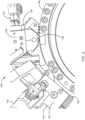
- FIGS. 3A and 3B illustrate side perspective views of the glue delivery system 100 showing the gun 130 extruding the glue to the leading edge 104 of the moving substrate 102 in accordance with the preferred embodiment of the present invention.
- the applicator drum 108 moves, the leading edge 104 of the moving substrate 102 reaches the first glue applicator 118.
- the bead of glue is fired from the gun 130 to the leading edge 104 of the moving substrate 102.
- the moving substrate 102 passes the gun 130 after the glue is extruded from the gun 130 on the leading edge 104 of the moving substrate 102 to the second glue applicator 120 as shown in FIG. 3B .
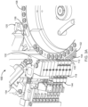
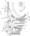
- FIGS. 4A and 4B illustrate side perspective views of the glue delivery system 100 showing the nozzle 136 extruding the glue to the trailing edge 106 of the moving substrate 102 in accordance with the preferred embodiment of the present invention.
- the moving substrate 102 has reached the nozzle 136 as shown in FIG. 4A and the trailing edge 106 of the moving substrate 102 placed in the trailing edge pad 114 of the applicator drum 108 is blown off over to the vertical oriented slit 142 to receive the smear of glue on the trailing edge 106 of the moving substrate 102 in a vertical orientation as shown in FIG. 4B .
- the glue extruded onto each moving substrate 102 has a designated pattern to be applied to the leading edge 104 and trailing edge 106 of each moving substrate 102.
- the plurality of solenoid valves 144 is opened and closed to apply the glue through the gun 130 and nozzle 136 to the leading edge 104 and trailing edge 106 of the moving substrate 102 respectively to create a designated leading edge glue pattern and a designated trailing edge glue pattern.
- the gear pump 122 adjusts the glue pressure in the first and second glue chambers 132, 138 to control designated glue patterns of deposits applied to the leading edge 104 and the trailing edge 106 of the moving substrate 102.
- the air pressure formed is controlled separately either manually or automatically by an analog pneumatic valve (not shown).
- the gear pump 122 connected to the at least one glue holding container 116 is precisely controlled by the servo drive 124 that is connected to the servomotor 126 utilizing the gear reducer 128.
- the gear pump 122 regulates the extrusion of the glue onto the moving substrate 102 that is programmed with data representative of a gear reducer ratio at which the glue flows within a constant speed, torque, current, speed and position of the glue at a desired temperature.
- the gear pump 122 is programmed to reference a data matrix that is data representative of the gear reducer ratio as a function of the pressure applied to the glue as the glue is provided to the gun 130 and nozzle 136 to be extruded.
- the data matrix is created by recording data during the empirical data acquisition process representative of a measured amount of the calibration glue deposited onto the moving substrate 102, information relating to the signal indicating the glue pressure drop, a torque and current empirical data and a gear reducer ratio empirical data and a speed of movement of the substrate 102 relative to the applicator drum 108.
- the amount of the calibration glue deposited onto the moving substrate 102 is measured by recording data that is representative of a weight of the calibration glue deposited onto the moving substrate 102.
- the amount of the calibration glue deposited onto the moving substrate 102 is further measured by recording data that is representative of a thickness of the calibration glue deposited onto the moving substrate 102.
- the torque and current drops and the gear reducer ratio of the gear pump 122 is changed to maintain a required torque and current on a main motor shaft 146.
- the glue pressure drop is measured by a pressure transducer 150 and modulated the glue pressure based upon a differential between the changed gear reducer ratio and the predetermined gear reducer ratio thereby achieving a precise pressure related to volume of a glue deposition and speed of the moving substrate 102 onto which the glue is applied.
- the invention also relates to a method of extruding glue according to claim 8.
- FIG. 5 illustrates a schematic view of an auxiliary motor shaft 152 connected to the main motor shaft 146 in accordance with the preferred embodiment of the present invention.
- the gear reducer ratio is predetermined by adding an axis of the auxiliary motor shaft 152 and an auxiliary shaft gear 154 with an axis of the main motor shaft 146 and the main shaft gear 148.
- the output of the main motor shaft axis is determined.
- the parameters of the main motor shaft axis are combined with the parameters of the auxiliary motor shaft axis to generate a differential gear 160 to determine the gear reducer ratio of the gear pump 122.
- the auxiliary motor shaft 152 and the auxiliary shaft gear 154 are in actual or virtual contact with the main motor shaft 146 and main shaft gear 148.
- FIG. 6 illustrates a flow diagram depicting the controls and processes by which the glue is extruded to the moving substrate 102 in the glue delivery system 100.
- the leading edge 104 and the trailing edge 106 of the moving substrate 102 are placed in the leading edge pad 112 and the trailing edge pad 114 of the applicator drum 108 respectively.
- the controlled amount of the glue is extruded from the at least one glue holding container 116 to the gun 130 of the first glue applicator 118 to the leading edge 104 of the moving substrate 102.
- the moving substrate 102 moves to the nozzle 136 where the trailing edge 106 of the moving substrate 102 is blown off over to the nozzle 136 to receive the smear of glue on the trailing edge 106 of the moving substrate 102 from the second glue applicator 120 that is connected to the at least one glue holding container 116.
- the servomotor 126 is connected to the gear pump 122 and to the programmable logic circuit (PLC) 156 via the servo drive 124.
- PLC programmable logic circuit
- the programmable logic circuit 156 determines and sends the appropriate on/off commands to the plurality of solenoid valves 144 of the first and second glue applicators 118, 120 respectively.
- the gear pump 122 is precisely controlled by the servo drive 124 utilizing the gear reducer 128.
- the gear pump 122 regulates the extrusion of the glue from the first and second glue applicators 118, 120 onto the moving substrate 102 that is programmed with data representative of a gear reducer ratio at which the glue flows within the constant speed, torque, current, speed and position of the glue at the desired temperature.
- a user machine interface (UMI) 158 provides a user the ability to input, for example, a selected length of the moving substrate 102, a selected position of the moving substrate 102, a selected width of the glue deposits on the leading edge 104 and trailing edge 106 of the moving substrate 102, a selected location of the glue deposits on the moving substrate 102, a selected leading edge glue pattern and a selected trailing edge pattern on the moving substrate 102.
- the position of the moving substrate 102 on the applicator drum 108 based on each segment of the applicator drum 108, glue firing and the moving substrate 102 blow over to the nozzle 136 are mechanically timed.
- the servo drive 124 is configured to receive inputs including information relating to the signal indicating the glue pressure drop, the torque and current empirical data and the gear reducer ratio empirical data generated during the empirical data acquisition process and the speed of movement of the substrate 102 relative to the applicator drum 108.
- the torque and current drops due to the extrusion of glue onto the moving substrate 102 the torque and current drops and the gear reducer ration of the gear pump 122 is changed to maintain a required torque and current on the main motor shaft 146 and the main shaft gear 148.
- the glue pressure drop is measured by the pressure transducer 150 and modulated the glue pressure based on a differential between the changed gear reducer ratio and the predetermined gear reducer ratio to achieve the precise pressure related to volume of the glue deposition and speed of the moving substrate 102 onto which the glue is applied.
Landscapes
- Engineering & Computer Science (AREA)
- Mechanical Engineering (AREA)
- Coating Apparatus (AREA)
- Application Of Or Painting With Fluid Materials (AREA)
Claims (12)
- Système de distribution de colle (100) pour extruder de la colle sur un substrat mobile (102), le système de distribution de colle (100) comprenant :au moins un récipient contenant de la colle (116) conçu pour contenir de la colle ;un premier applicateur de colle (118) ayant un pistolet (130) fixé à une première chambre à colle (132) qui est reliée à l'au moins un récipient contenant de la colle (116) au moyen d'un premier tuyau (134) ;le système de distribution de colle (100) étant conçu pour extruder une quantité régulée de colle depuis l'au moins un récipient contenant de la colle (116) à travers le premier tuyau (134) vers la première chambre de colle (132) et vers le pistolet (130) et à travers le pistolet (130) vers un bord d'attaque (104) du substrat mobile (102) placé dans un tampon de bord d'attaque (112) d'un tambour applicateur (108) ; et,un second applicateur de colle (120) ayant une buse (136) fixée à une seconde chambre à colle (138) qui est reliée à l'au moins un récipient à colle (116) au moyen d'un second tuyau (140) ;le système de distribution de colle (100) étant conçu pour extruder une quantité régulée de colle depuis l'au moins un récipient contenant de la colle (116) à travers le second tuyau (140) vers la seconde chambre de colle (138) et vers la buse (136), et pour souffler un bord de fuite (106) du substrat mobile (102), placé dans un tampon de bord de fuite (114) du tambour applicateur (108), sur la buse (136) pour recevoir une bavure de colle sur le bord de fuite (106) du substrat mobile (102) ; et,le système de distribution de colle (100) comprenant en outre :un servomoteur (124), un servomoteur (126) comprenant un arbre moteur principal (146), un engrenage réducteur (128) et une pompe à engrenages (122) reliée à l'au moins un récipient contenant de la colle (116), la pompe à engrenages (122) étant commandée avec précision par le servomoteur (124), par l'intermédiaire du servomoteur (126), au moyen de l'engrenage réducteur (128) ;la pompe à engrenages (122) étant conçue pour réguler l'extrusion de la colle sur le substrat mobile (102), le système de distribution de colle (100) étant caractérisé en ce quela pompe à engrenages (122) est programmée avec des données représentatives d'un rapport d'engrenage réducteur auquel la colle s'écoule à une vitesse, un couple, un flux, une vitesse et une position constants de la colle à une température souhaitée, la pompe à engrenages (122) étant programmée pour référencer une matrice de données comprenant des données représentatives du rapport d'engrenage réducteur en fonction de la pression appliquée à la colle lorsque la colle est fournie au pistolet (130) et à la buse (136) pour être extrudée, ladite matrice de données étant créée en enregistrant des données pendant un processus d'acquisition de données empiriques représentatives d'une quantité mesurée d'une colle d'étalonnage déposée sur le substrat mobile (102), des informations relatives à un signal indiquant une diminution de pression de la colle, des données empiriques de couple et de flux relatives à l'arbre moteur principal (146) du servomoteur (126), des données empiriques de rapport d'engrenage réducteur, et une vitesse de mouvement du substrat mobile (102) par rapport au tambour applicateur (108) ;le système de distribution de colle (100) étant conçu de sorte que, lorsque la pression de la colle diminue en raison de l'extrusion de la colle sur le substrat mobile (102), le couple et le flux sur l'arbre moteur principal (146) du servomoteur (126) diminuent, et le rapport d'engrenage réducteur de la pompe à engrenages (122) est modifié pour maintenir un couple et un flux requis sur l'arbre moteur principal (146) du servomoteur (126),moyennant quoi le système de distribution de colle (100) est conçu pour mesurer la diminution de pression de la colle et pour moduler la pression de la colle sur la base d'un différentiel entre le rapport d'engrenage réducteur modifié et un rapport d'engrenage réducteur prédéfini, obtenant ainsi une pression précise de dépôt de colle liée à un volume du dépôt de colle et à la vitesse du substrat mobile (102) sur lequel la colle est appliquée.
- Système de distribution de colle (100) selon la revendication 1, la pompe à engrenages (122) étant conçue pour être alimentée par le servomoteur (126).
- Système de distribution de colle (100) selon la revendication 1, la pompe à engrenages (122) étant conçue pour ajuster la pression de colle dans les première et seconde chambres de colle (132, 138) pour commander les motifs de colle désignés des dépôts appliqués au bord d'attaque (104) et au bord de fuite (106) du substrat mobile (102).
- Système de distribution de colle (100) selon la revendication 3, le motif de colle désigné au niveau du bord d'attaque (104) étant un cordon de colle qui est extrudé par le pistolet (130).
- Système de distribution de colle (100) selon la revendication 3, le motif de colle désigné au niveau du bord d'attaque (106) étant une bavure verticale qui est extrudée d'une fente orientée verticalement (142) de la buse (136).
- Système de distribution de colle (100) selon la revendication 1, le système de distribution de colle (100) étant conçu de sorte que lorsque la colle est extrudée du pistolet (130) et de la buse (136), une pression d'air formée soit régulée séparément soit manuellement soit automatiquement par une vanne pneumatique analogique.
- Système de distribution de colle (100) selon la revendication 1, le rapport d'engrenage réducteur étant prédéfini en incluant un axe d'arbre de moteur auxiliaire et un engrenage d'arbre auxiliaire avec un axe d'arbre de moteur principal et un engrenage d'arbre principal (148), en changeant les paramètres de l'axe d'arbre de moteur auxiliaire pour déterminer les paramètres de l'axe d'arbre de moteur principal et en combinant les paramètres de l'axe d'arbre de moteur auxiliaire et de l'axe d'arbre de moteur principal.
- Procédé d'extrusion de colle à l'aide d'un système de distribution de colle (100) selon l'une quelconque des revendications 1 à 7, le procédé comprenant les étapes suivantes :application d'un rapport d'engrenage réducteur prédéfini à un couple, un flux, une vitesse et une position constants de la colle à une température souhaitée ;extrusion d'une quantité régulée de colle depuis le récipient contenant de la colle (116) à travers le premier tuyau (134) vers la première chambre de colle (132) et vers le pistolet (130) du premier applicateur de colle (118) et à travers le pistolet (130) vers le bord d'attaque (104) du substrat mobile (102) placé dans le tampon de bord d'attaque (112) du tambour applicateur (108) ; etextrusion d'une quantité régulée de colle depuis le récipient contenant de la colle (116) à travers le second tuyau (140) vers la seconde chambre de colle (138) et vers la buse (136) du second applicateur de colle (120) ; et,soufflage du bord de fuite (106) du substrat mobile (102) placé dans le tampon de bord de fuite (114) du tambour applicateur (108) vers la buse (136), pour recevoir une bavure de colle sur le bord de fuite (106) du substrat mobile (102) ;moyennant quoi, lorsque la pression de la colle diminue en raison de l'extrusion de la colle sur le substrat mobile (102), le couple et le flux sur l'arbre moteur principal (146) du servomoteur (126) diminuent, et le rapport d'engrenage réducteur de la pompe à engrenages (122) est modifié pour maintenir un couple et un flux requis sur l'arbre moteur principal (146) du servomoteur (126),la diminution de pression de la colle étant mesurée et modulée sur la base d'un différentiel entre le rapport d'engrenage réducteur modifié et le rapport d'engrenage réducteur prédéfini, obtenant ainsi une pression précise liée à un volume du dépôt de colle et à la vitesse du substrat mobile (102) sur lequel la colle est appliquée pendant les étapes d'extrusion.
- Procédé selon la revendication 8, l'étape de prédétermination du rapport d'engrenage réducteur comprenant l'addition d'un axe d'arbre de moteur auxiliaire et d'un engrenage d'arbre auxiliaire avec un axe d'arbre de moteur principal et un engrenage d'arbre principal qui sont positionnés au niveau de la pompe à engrenages (122).
- Procédé selon la revendication 9, l'étape de prédétermination du rapport d'engrenage réducteur comprenant en outre la modification des paramètres de l'axe d'arbre de moteur auxiliaire pour déterminer l'axe d'arbre de moteur principal.
- Procédé selon la revendication 8, l'étape de mesure de la quantité de colle d'étalonnage déposée sur le substrat mobile (102) comprenant l'enregistrement de données qui sont représentatives d'un poids de la colle d'étalonnage déposée sur le substrat mobile (102).
- Procédé selon la revendication 8, l'étape de mesure de la quantité de colle d'étalonnage déposée sur le substrat mobile (102) comprenant en outre l'enregistrement de données qui sont représentatives d'une épaisseur de la colle d'étalonnage déposée sur le substrat mobile (102).
Priority Applications (1)
| Application Number | Priority Date | Filing Date | Title |
|---|---|---|---|
| EP23155426.2A EP4219024A3 (fr) | 2016-01-26 | 2016-05-12 | Système de distribution de colle |
Applications Claiming Priority (2)
| Application Number | Priority Date | Filing Date | Title |
|---|---|---|---|
| US15/006,471 US9789645B2 (en) | 2016-01-26 | 2016-01-26 | Glue delivery system |
| PCT/US2016/032156 WO2017131804A1 (fr) | 2016-01-26 | 2016-05-12 | Système de distribution de colle |
Related Child Applications (1)
| Application Number | Title | Priority Date | Filing Date |
|---|---|---|---|
| EP23155426.2A Division EP4219024A3 (fr) | 2016-01-26 | 2016-05-12 | Système de distribution de colle |
Publications (3)
| Publication Number | Publication Date |
|---|---|
| EP3408035A1 EP3408035A1 (fr) | 2018-12-05 |
| EP3408035A4 EP3408035A4 (fr) | 2019-01-09 |
| EP3408035B1 true EP3408035B1 (fr) | 2023-02-08 |
Family
ID=59359436
Family Applications (2)
| Application Number | Title | Priority Date | Filing Date |
|---|---|---|---|
| EP23155426.2A Pending EP4219024A3 (fr) | 2016-01-26 | 2016-05-12 | Système de distribution de colle |
| EP16888531.7A Active EP3408035B1 (fr) | 2016-01-26 | 2016-05-12 | Système de distribution de colle |
Family Applications Before (1)
| Application Number | Title | Priority Date | Filing Date |
|---|---|---|---|
| EP23155426.2A Pending EP4219024A3 (fr) | 2016-01-26 | 2016-05-12 | Système de distribution de colle |
Country Status (3)
| Country | Link |
|---|---|
| US (2) | US9789645B2 (fr) |
| EP (2) | EP4219024A3 (fr) |
| WO (1) | WO2017131804A1 (fr) |
Families Citing this family (10)
| Publication number | Priority date | Publication date | Assignee | Title |
|---|---|---|---|---|
| US9919909B2 (en) * | 2016-08-12 | 2018-03-20 | Arbel Agencies Limited | Syrup pump and controller |
| US10227198B1 (en) * | 2018-03-12 | 2019-03-12 | Maan Intellectual Properties B.V. | Device for producing both linerless labels and lined labels |
| DE102018220354A1 (de) * | 2018-11-27 | 2020-05-28 | Krones Ag | Verfahren zum Aufspritzen von Kaltleim auf Etiketten und Etikettieraggregat für Behälter |
| DE102020101845A1 (de) | 2020-01-27 | 2021-07-29 | Krones Aktiengesellschaft | Verfahren zum Aufspritzen von Kaltleim auf Paletten für Etiketten und Etikettieraggregat für Behälter |
| CN111672701B (zh) * | 2020-05-26 | 2022-02-11 | 厦门鑫奥格自动化设备有限公司 | 一种挤压式点胶针 |
| CN112958399B (zh) * | 2021-04-07 | 2023-12-01 | 浙江仕金自动化科技有限公司 | 一种用于灌胶机的压力检测系统及其检测方法 |
| CN114713461B (zh) * | 2022-04-07 | 2023-11-03 | 利能(佛山市)塑料制品有限公司 | 一种控制液体流量装置 |
| CN115069507B (zh) * | 2022-06-21 | 2024-01-12 | 贵州永吉盛珑包装有限公司 | 一种点胶机用出胶可变配比组件 |
| CN117179420B (zh) * | 2023-09-08 | 2024-08-09 | 温州国仕邦高分子材料有限公司 | 一种基于胶水周转桶的鞋用pu胶供胶方法及系统 |
| CN119078145A (zh) * | 2024-11-07 | 2024-12-06 | 江苏嗨佩兔科技有限公司 | 一种用于电缆加工的橡胶制品挤出设备 |
Family Cites Families (64)
| Publication number | Priority date | Publication date | Assignee | Title |
|---|---|---|---|---|
| US3046935A (en) | 1957-05-24 | 1962-07-31 | S & S Corrugated Paper Mach | Gluing control means |
| US3582428A (en) | 1969-04-17 | 1971-06-01 | Pacific Adhesives Co Inc | Plywood manufacture with controlled glue spread |
| GB1266745A (fr) | 1969-06-11 | 1972-03-15 | ||
| DE1950149A1 (de) | 1969-10-04 | 1971-04-15 | Hermann Kronseder | Etikettiervorrichtung fuer Etikettiermaschinen |
| US3643699A (en) | 1970-05-18 | 1972-02-22 | Textron Inc | Torque motor operated valve |
| US4041864A (en) | 1972-05-09 | 1977-08-16 | Dahlgren Manufacturing Company | Method and apparatus for inking printing plates |
| US4013037A (en) | 1975-03-27 | 1977-03-22 | Airprint Systems, Inc. | Apparatus for controllably applying liquids to a moving surface |
| DE2838158C3 (de) | 1978-09-01 | 1982-12-16 | Jagenberg-Werke AG, 4000 Düsseldorf | Beleimungsvorrichtung für eine Etikettiermaschine |
| US4389971A (en) | 1979-04-16 | 1983-06-28 | Copar Corporation | Means for controlling the application of glue to a defined area |
| US4360538A (en) | 1981-03-19 | 1982-11-23 | Molins Machine Company, Inc. | Glue machine automatic rider roll |
| GB2142257B (en) | 1983-07-02 | 1986-11-26 | Gen Motors Overseas | Adhesive application apparatus |
| US4787332A (en) | 1986-02-12 | 1988-11-29 | Robotics, Inc. | Adhesive dispensing pump control system |
| US4699575A (en) | 1986-02-12 | 1987-10-13 | Robotics, Inc. | Adhesive pump and it's control system |
| US4822647A (en) | 1986-04-23 | 1989-04-18 | Honda Giken Kogyo Kabushiki Kaisha | Coating agent to coating robot, including a method and arrangement for protecting the apparatus from damage due to improper pressures in a supply line |
| US4733310A (en) | 1986-05-23 | 1988-03-22 | Ziyad, Inc. | Paper sheet and envelope feeder apparatus |
| SE456727B (sv) | 1987-03-11 | 1988-10-31 | Inst Verkstadstek Forsk Ivf | Anordning foer att frammata och paafoera en viskoes substans |
| JPH0633128B2 (ja) | 1987-05-22 | 1994-05-02 | 守男 水谷 | 糊付け装置 |
| US4848659A (en) | 1987-06-08 | 1989-07-18 | American Building Restoration Chemicals, Inc. | Electric stripper applicator |
| IT1217478B (it) | 1988-05-03 | 1990-03-22 | Comelz Spa | Macchina incollatrice e ripiegatrice dei bordi pepiferici di materiali in fogli e simili,operativamente asservita a programmazione elettronica dei suoi parametri funzionali |
| US4938388A (en) | 1989-05-05 | 1990-07-03 | Future Co., Ltd. | Glue transport mechanism for a molten glue discharging device |
| US5215131A (en) | 1991-11-14 | 1993-06-01 | Poy George L | Automatic liquid delivery system |
| US5675913A (en) | 1993-03-31 | 1997-10-14 | Fuji Photo Film Co., Ltd. | Photosensitive material processing apparatus |
| US5407523A (en) | 1993-08-13 | 1995-04-18 | Outboard Marine Corporation | Apparatus for assembling lost foam casting patterns |
| US5443683A (en) | 1993-09-24 | 1995-08-22 | Garrett; Jimmy R. | Glue unit |
| DE4410401A1 (de) | 1994-03-26 | 1995-09-28 | Adolf Schnell | Handgetriebe |
| US5904804A (en) | 1995-09-06 | 1999-05-18 | Matsushita Electric Industrial Co., Ltd. | Battery label wrapping method and apparatus |
| US5996650A (en) | 1996-11-15 | 1999-12-07 | Oden Corporation | Net mass liquid filler |
| US5827162A (en) | 1997-01-02 | 1998-10-27 | The Langston Corporation | Folder/gluer machine for paperboard blanks |
| FR2765191B1 (fr) | 1997-06-26 | 1999-08-20 | Cermex | Procede et machine de collage automatique d'un film plastique thermoretractable sur le fond d'une caisse ouverte |
| US6085943A (en) | 1997-06-30 | 2000-07-11 | Speedline Technologies, Inc. | Controllable liquid dispensing device |
| US6296463B1 (en) | 1998-04-20 | 2001-10-02 | Nordson Corporation | Segmented metering die for hot melt adhesives or other polymer melts |
| US6422428B1 (en) | 1998-04-20 | 2002-07-23 | Nordson Corporation | Segmented applicator for hot melt adhesives or other thermoplastic materials |
| US6056229A (en) | 1998-12-03 | 2000-05-02 | Paper Converting Machine Co. | Surface winder with pinch cutoff |
| US6511301B1 (en) | 1999-11-08 | 2003-01-28 | Jeffrey Fugere | Fluid pump and cartridge |
| US6957783B1 (en) | 1999-01-26 | 2005-10-25 | Dl Technology Llc | Dispense tip with vented outlets |
| US6866881B2 (en) | 1999-02-19 | 2005-03-15 | Speedline Technologies, Inc. | Dispensing system and method |
| US6892959B1 (en) | 2000-01-26 | 2005-05-17 | Dl Technology Llc | System and method for control of fluid dispense pump |
| US6993887B2 (en) | 2000-08-07 | 2006-02-07 | Dsd Communications, Inc. | System and method for including packets with goods during automated packaging |
| US6630028B2 (en) * | 2000-12-08 | 2003-10-07 | Glass Equipment Development, Inc. | Controlled dispensing of material |
| US6710566B2 (en) | 2001-10-01 | 2004-03-23 | Chicago Industrial Group, Inc. | Method and apparatus for servo glue gap control |
| JP2005521603A (ja) | 2002-03-28 | 2005-07-21 | ザ プロクター アンド ギャンブル カンパニー | 膠を箱に塗布するための方法及び装置 |
| US6983867B1 (en) | 2002-04-29 | 2006-01-10 | Dl Technology Llc | Fluid dispense pump with drip prevention mechanism and method for controlling same |
| US7574947B2 (en) | 2002-05-29 | 2009-08-18 | Massachusetts Institute Of Technology | Rotary fast tool servo system and methods |
| US6892512B2 (en) | 2002-08-07 | 2005-05-17 | Medco Health Solutions, Inc. | Automated prescription filling system/method with automated labeling and packaging system/method automated order consolidation system/method |
| ATE486664T1 (de) | 2003-08-11 | 2010-11-15 | Procter & Gamble | Verfahren zum auftragen von klebstoff |
| US7267153B2 (en) | 2004-03-02 | 2007-09-11 | Herbert B Kohler | Corrugator glue machine having web tension nulling mechanism |
| US7771556B2 (en) | 2005-07-01 | 2010-08-10 | Nordson Corporation | Apparatus and process to apply adhesive during labeling operations |
| DE502005010764D1 (de) | 2005-10-25 | 2011-02-10 | Mueller Martini Holding Ag | Einrichtung für das Beleimen der Aussenflächen von Buchblocks |
| DE102006017365A1 (de) | 2006-04-11 | 2007-10-18 | Khs Ag | Beleimungsvorrichtung |
| ATE516966T1 (de) | 2006-06-30 | 2011-08-15 | Mueller Martini Holding Ag | Leimwerk für buchblocks mit verstellbarer rakel |
| US8915280B1 (en) | 2006-12-15 | 2014-12-23 | Glenn Robell | System and method for applying adhesive, buffer, and/or liner to I-joists |
| DE102007040626A1 (de) | 2007-08-27 | 2009-03-05 | Heidelberger Druckmaschinen Ag | Faltschachtelklebemaschine mit verbesserter Zugänglichkeit |
| JP5382299B2 (ja) | 2008-09-24 | 2014-01-08 | 株式会社Isowa | フォルダグルア |
| US20100236712A1 (en) | 2009-03-18 | 2010-09-23 | Thomas Michael Basgil | Fully automatic rfid labeler |
| US8517656B2 (en) | 2010-01-08 | 2013-08-27 | Goss International Americas, Inc. | Cover applier and method of aligning a book image to a cover image |
| WO2011123503A1 (fr) | 2010-04-01 | 2011-10-06 | B & H Manufacturing Company, Inc. | Système d'application d'extrusion |
| US20120048889A1 (en) | 2010-08-26 | 2012-03-01 | Huang Yung-Kuan | Pusher Unit of Glue Applicator |
| WO2013155096A1 (fr) | 2012-04-09 | 2013-10-17 | Tension Envelope Corporation | Système de profilage de fenêtre |
| HU229852B1 (en) | 2012-08-15 | 2014-10-28 | Hibar Systems Ltd Richmond Hill | Electronically controlled and driven linear pump actuator |
| DE102012219554A1 (de) | 2012-10-25 | 2014-04-30 | Krones Ag | Leimwerk |
| DE102012219552A1 (de) | 2012-10-25 | 2014-04-30 | Krones Ag | Leimwalze für eine Etikettiervorrichtung |
| DE102012113077A1 (de) | 2012-12-22 | 2014-06-26 | Krones Ag | Entnahmeeinrichtung zur entnahme von etiketten, etikett und verfahren zum beleimen eines etiketts |
| US8920096B2 (en) | 2012-12-27 | 2014-12-30 | Donnie Donselman | Book binding adhesive application controller |
| DE102013206886A1 (de) | 2013-04-17 | 2014-10-23 | Krones Ag | Leimbehälter für Heissleimapplikationen |
-
2016
- 2016-01-26 US US15/006,471 patent/US9789645B2/en active Active
- 2016-05-12 EP EP23155426.2A patent/EP4219024A3/fr active Pending
- 2016-05-12 EP EP16888531.7A patent/EP3408035B1/fr active Active
- 2016-05-12 WO PCT/US2016/032156 patent/WO2017131804A1/fr not_active Ceased
-
2017
- 2017-10-16 US US15/785,323 patent/US10029411B2/en active Active
Also Published As
| Publication number | Publication date |
|---|---|
| US20180036960A1 (en) | 2018-02-08 |
| EP4219024A2 (fr) | 2023-08-02 |
| EP4219024A3 (fr) | 2023-09-27 |
| US9789645B2 (en) | 2017-10-17 |
| EP3408035A1 (fr) | 2018-12-05 |
| US20170210061A1 (en) | 2017-07-27 |
| WO2017131804A1 (fr) | 2017-08-03 |
| US10029411B2 (en) | 2018-07-24 |
| EP3408035A4 (fr) | 2019-01-09 |
Similar Documents
| Publication | Publication Date | Title |
|---|---|---|
| EP3408035B1 (fr) | Système de distribution de colle | |
| US9186695B2 (en) | Extrusion application system | |
| US8334023B2 (en) | Methods for regulating the placement of fluid dispensed from an applicator onto a workpiece | |
| JP5635233B2 (ja) | ラベリング工程時に接着剤を塗布する装置及び方法 | |
| EP2176317B1 (fr) | Appareil et procedes de distribution d'adhesif sur des etiquettes | |
| EP1095709A2 (fr) | Procédé et appareil de distribution d'un fluide sur des substrats | |
| US5540774A (en) | Drip proof dispensing method and nozzle assembly for dispensing viscous materials | |
| US6206963B1 (en) | Nozzle | |
| JP4510472B2 (ja) | 包装材に接着剤を付与する方法と装置 | |
| US5305955A (en) | Nozzle bar with adjustable pattern | |
| JPH0575599B2 (fr) | ||
| JP4022785B2 (ja) | 塗布パターンの位置ずれを検知する方法及びその補正方法 | |
| CN100478967C (zh) | 调节从敷涂器施放到工件上的流体的布置的方法 | |
| EP3641949B1 (fr) | Appareil et procédé pour appliquer un adhésif sur une bande en mouvement | |
| US6932870B2 (en) | System and process for dispensing an adhesive onto a core during the formation of rolled products | |
| US7320814B2 (en) | Methods for applying a liquid to a web | |
| EP0025007A1 (fr) | Applicateur d'adhésif et procédé pour relier des cigarettes avec des filtres et applications analogues | |
| US4391856A (en) | Adhesive applicator and method for cigarette-to-filter adhesion and similar applications | |
| US20020090448A1 (en) | Method, assembly and unit for gumming articles | |
| US12186773B2 (en) | Tread-line paint applicator | |
| KR20000052379A (ko) | 밴더롤 접착 장치 및 방법 |
Legal Events
| Date | Code | Title | Description |
|---|---|---|---|
| STAA | Information on the status of an ep patent application or granted ep patent |
Free format text: STATUS: THE INTERNATIONAL PUBLICATION HAS BEEN MADE |
|
| PUAI | Public reference made under article 153(3) epc to a published international application that has entered the european phase |
Free format text: ORIGINAL CODE: 0009012 |
|
| STAA | Information on the status of an ep patent application or granted ep patent |
Free format text: STATUS: REQUEST FOR EXAMINATION WAS MADE |
|
| 17P | Request for examination filed |
Effective date: 20180719 |
|
| AK | Designated contracting states |
Kind code of ref document: A1 Designated state(s): AL AT BE BG CH CY CZ DE DK EE ES FI FR GB GR HR HU IE IS IT LI LT LU LV MC MK MT NL NO PL PT RO RS SE SI SK SM TR |
|
| AX | Request for extension of the european patent |
Extension state: BA ME |
|
| A4 | Supplementary search report drawn up and despatched |
Effective date: 20181211 |
|
| RIC1 | Information provided on ipc code assigned before grant |
Ipc: B05C 11/10 20060101AFI20181205BHEP Ipc: B05C 5/02 20060101ALI20181205BHEP |
|
| DAV | Request for validation of the european patent (deleted) | ||
| DAX | Request for extension of the european patent (deleted) | ||
| RAP1 | Party data changed (applicant data changed or rights of an application transferred) |
Owner name: ELUM INC. |
|
| STAA | Information on the status of an ep patent application or granted ep patent |
Free format text: STATUS: EXAMINATION IS IN PROGRESS |
|
| 17Q | First examination report despatched |
Effective date: 20211214 |
|
| GRAP | Despatch of communication of intention to grant a patent |
Free format text: ORIGINAL CODE: EPIDOSNIGR1 |
|
| STAA | Information on the status of an ep patent application or granted ep patent |
Free format text: STATUS: GRANT OF PATENT IS INTENDED |
|
| INTG | Intention to grant announced |
Effective date: 20220824 |
|
| GRAS | Grant fee paid |
Free format text: ORIGINAL CODE: EPIDOSNIGR3 |
|
| GRAA | (expected) grant |
Free format text: ORIGINAL CODE: 0009210 |
|
| STAA | Information on the status of an ep patent application or granted ep patent |
Free format text: STATUS: THE PATENT HAS BEEN GRANTED |
|
| AK | Designated contracting states |
Kind code of ref document: B1 Designated state(s): AL AT BE BG CH CY CZ DE DK EE ES FI FR GB GR HR HU IE IS IT LI LT LU LV MC MK MT NL NO PL PT RO RS SE SI SK SM TR |
|
| REG | Reference to a national code |
Ref country code: GB Ref legal event code: FG4D |
|
| REG | Reference to a national code |
Ref country code: CH Ref legal event code: EP Ref country code: AT Ref legal event code: REF Ref document number: 1547320 Country of ref document: AT Kind code of ref document: T Effective date: 20230215 |
|
| REG | Reference to a national code |
Ref country code: IE Ref legal event code: FG4D |
|
| REG | Reference to a national code |
Ref country code: DE Ref legal event code: R096 Ref document number: 602016077790 Country of ref document: DE |
|
| RAP4 | Party data changed (patent owner data changed or rights of a patent transferred) |
Owner name: ELUM INC. |
|
| REG | Reference to a national code |
Ref country code: LT Ref legal event code: MG9D |
|
| REG | Reference to a national code |
Ref country code: NL Ref legal event code: MP Effective date: 20230208 |
|
| REG | Reference to a national code |
Ref country code: AT Ref legal event code: MK05 Ref document number: 1547320 Country of ref document: AT Kind code of ref document: T Effective date: 20230208 |
|
| PG25 | Lapsed in a contracting state [announced via postgrant information from national office to epo] |
Ref country code: RS Free format text: LAPSE BECAUSE OF FAILURE TO SUBMIT A TRANSLATION OF THE DESCRIPTION OR TO PAY THE FEE WITHIN THE PRESCRIBED TIME-LIMIT Effective date: 20230208 Ref country code: PT Free format text: LAPSE BECAUSE OF FAILURE TO SUBMIT A TRANSLATION OF THE DESCRIPTION OR TO PAY THE FEE WITHIN THE PRESCRIBED TIME-LIMIT Effective date: 20230609 Ref country code: NO Free format text: LAPSE BECAUSE OF FAILURE TO SUBMIT A TRANSLATION OF THE DESCRIPTION OR TO PAY THE FEE WITHIN THE PRESCRIBED TIME-LIMIT Effective date: 20230508 Ref country code: NL Free format text: LAPSE BECAUSE OF FAILURE TO SUBMIT A TRANSLATION OF THE DESCRIPTION OR TO PAY THE FEE WITHIN THE PRESCRIBED TIME-LIMIT Effective date: 20230208 Ref country code: LV Free format text: LAPSE BECAUSE OF FAILURE TO SUBMIT A TRANSLATION OF THE DESCRIPTION OR TO PAY THE FEE WITHIN THE PRESCRIBED TIME-LIMIT Effective date: 20230208 Ref country code: LT Free format text: LAPSE BECAUSE OF FAILURE TO SUBMIT A TRANSLATION OF THE DESCRIPTION OR TO PAY THE FEE WITHIN THE PRESCRIBED TIME-LIMIT Effective date: 20230208 Ref country code: HR Free format text: LAPSE BECAUSE OF FAILURE TO SUBMIT A TRANSLATION OF THE DESCRIPTION OR TO PAY THE FEE WITHIN THE PRESCRIBED TIME-LIMIT Effective date: 20230208 Ref country code: ES Free format text: LAPSE BECAUSE OF FAILURE TO SUBMIT A TRANSLATION OF THE DESCRIPTION OR TO PAY THE FEE WITHIN THE PRESCRIBED TIME-LIMIT Effective date: 20230208 Ref country code: AT Free format text: LAPSE BECAUSE OF FAILURE TO SUBMIT A TRANSLATION OF THE DESCRIPTION OR TO PAY THE FEE WITHIN THE PRESCRIBED TIME-LIMIT Effective date: 20230208 |
|
| PG25 | Lapsed in a contracting state [announced via postgrant information from national office to epo] |
Ref country code: SE Free format text: LAPSE BECAUSE OF FAILURE TO SUBMIT A TRANSLATION OF THE DESCRIPTION OR TO PAY THE FEE WITHIN THE PRESCRIBED TIME-LIMIT Effective date: 20230208 Ref country code: PL Free format text: LAPSE BECAUSE OF FAILURE TO SUBMIT A TRANSLATION OF THE DESCRIPTION OR TO PAY THE FEE WITHIN THE PRESCRIBED TIME-LIMIT Effective date: 20230208 Ref country code: IS Free format text: LAPSE BECAUSE OF FAILURE TO SUBMIT A TRANSLATION OF THE DESCRIPTION OR TO PAY THE FEE WITHIN THE PRESCRIBED TIME-LIMIT Effective date: 20230608 Ref country code: GR Free format text: LAPSE BECAUSE OF FAILURE TO SUBMIT A TRANSLATION OF THE DESCRIPTION OR TO PAY THE FEE WITHIN THE PRESCRIBED TIME-LIMIT Effective date: 20230509 Ref country code: FI Free format text: LAPSE BECAUSE OF FAILURE TO SUBMIT A TRANSLATION OF THE DESCRIPTION OR TO PAY THE FEE WITHIN THE PRESCRIBED TIME-LIMIT Effective date: 20230208 |
|
| PG25 | Lapsed in a contracting state [announced via postgrant information from national office to epo] |
Ref country code: SM Free format text: LAPSE BECAUSE OF FAILURE TO SUBMIT A TRANSLATION OF THE DESCRIPTION OR TO PAY THE FEE WITHIN THE PRESCRIBED TIME-LIMIT Effective date: 20230208 Ref country code: RO Free format text: LAPSE BECAUSE OF FAILURE TO SUBMIT A TRANSLATION OF THE DESCRIPTION OR TO PAY THE FEE WITHIN THE PRESCRIBED TIME-LIMIT Effective date: 20230208 Ref country code: EE Free format text: LAPSE BECAUSE OF FAILURE TO SUBMIT A TRANSLATION OF THE DESCRIPTION OR TO PAY THE FEE WITHIN THE PRESCRIBED TIME-LIMIT Effective date: 20230208 Ref country code: DK Free format text: LAPSE BECAUSE OF FAILURE TO SUBMIT A TRANSLATION OF THE DESCRIPTION OR TO PAY THE FEE WITHIN THE PRESCRIBED TIME-LIMIT Effective date: 20230208 Ref country code: CZ Free format text: LAPSE BECAUSE OF FAILURE TO SUBMIT A TRANSLATION OF THE DESCRIPTION OR TO PAY THE FEE WITHIN THE PRESCRIBED TIME-LIMIT Effective date: 20230208 |
|
| REG | Reference to a national code |
Ref country code: DE Ref legal event code: R097 Ref document number: 602016077790 Country of ref document: DE |
|
| PG25 | Lapsed in a contracting state [announced via postgrant information from national office to epo] |
Ref country code: SK Free format text: LAPSE BECAUSE OF FAILURE TO SUBMIT A TRANSLATION OF THE DESCRIPTION OR TO PAY THE FEE WITHIN THE PRESCRIBED TIME-LIMIT Effective date: 20230208 |
|
| PLBE | No opposition filed within time limit |
Free format text: ORIGINAL CODE: 0009261 |
|
| STAA | Information on the status of an ep patent application or granted ep patent |
Free format text: STATUS: NO OPPOSITION FILED WITHIN TIME LIMIT |
|
| REG | Reference to a national code |
Ref country code: CH Ref legal event code: PL |
|
| 26N | No opposition filed |
Effective date: 20231109 |
|
| PG25 | Lapsed in a contracting state [announced via postgrant information from national office to epo] |
Ref country code: MC Free format text: LAPSE BECAUSE OF FAILURE TO SUBMIT A TRANSLATION OF THE DESCRIPTION OR TO PAY THE FEE WITHIN THE PRESCRIBED TIME-LIMIT Effective date: 20230208 |
|
| REG | Reference to a national code |
Ref country code: BE Ref legal event code: MM Effective date: 20230531 |
|
| PG25 | Lapsed in a contracting state [announced via postgrant information from national office to epo] |
Ref country code: SI Free format text: LAPSE BECAUSE OF FAILURE TO SUBMIT A TRANSLATION OF THE DESCRIPTION OR TO PAY THE FEE WITHIN THE PRESCRIBED TIME-LIMIT Effective date: 20230208 Ref country code: MC Free format text: LAPSE BECAUSE OF FAILURE TO SUBMIT A TRANSLATION OF THE DESCRIPTION OR TO PAY THE FEE WITHIN THE PRESCRIBED TIME-LIMIT Effective date: 20230208 Ref country code: LU Free format text: LAPSE BECAUSE OF NON-PAYMENT OF DUE FEES Effective date: 20230512 Ref country code: LI Free format text: LAPSE BECAUSE OF NON-PAYMENT OF DUE FEES Effective date: 20230531 Ref country code: CH Free format text: LAPSE BECAUSE OF NON-PAYMENT OF DUE FEES Effective date: 20230531 |
|
| REG | Reference to a national code |
Ref country code: IE Ref legal event code: MM4A |
|
| PG25 | Lapsed in a contracting state [announced via postgrant information from national office to epo] |
Ref country code: IE Free format text: LAPSE BECAUSE OF NON-PAYMENT OF DUE FEES Effective date: 20230512 |
|
| PG25 | Lapsed in a contracting state [announced via postgrant information from national office to epo] |
Ref country code: IE Free format text: LAPSE BECAUSE OF NON-PAYMENT OF DUE FEES Effective date: 20230512 |
|
| PG25 | Lapsed in a contracting state [announced via postgrant information from national office to epo] |
Ref country code: BE Free format text: LAPSE BECAUSE OF NON-PAYMENT OF DUE FEES Effective date: 20230531 |
|
| PG25 | Lapsed in a contracting state [announced via postgrant information from national office to epo] |
Ref country code: BG Free format text: LAPSE BECAUSE OF FAILURE TO SUBMIT A TRANSLATION OF THE DESCRIPTION OR TO PAY THE FEE WITHIN THE PRESCRIBED TIME-LIMIT Effective date: 20230208 |
|
| PG25 | Lapsed in a contracting state [announced via postgrant information from national office to epo] |
Ref country code: BG Free format text: LAPSE BECAUSE OF FAILURE TO SUBMIT A TRANSLATION OF THE DESCRIPTION OR TO PAY THE FEE WITHIN THE PRESCRIBED TIME-LIMIT Effective date: 20230208 |
|
| PGFP | Annual fee paid to national office [announced via postgrant information from national office to epo] |
Ref country code: DE Payment date: 20250528 Year of fee payment: 10 |
|
| PGFP | Annual fee paid to national office [announced via postgrant information from national office to epo] |
Ref country code: GB Payment date: 20250411 Year of fee payment: 10 |
|
| PGFP | Annual fee paid to national office [announced via postgrant information from national office to epo] |
Ref country code: IT Payment date: 20250522 Year of fee payment: 10 |
|
| PGFP | Annual fee paid to national office [announced via postgrant information from national office to epo] |
Ref country code: FR Payment date: 20250527 Year of fee payment: 10 |
|
| PG25 | Lapsed in a contracting state [announced via postgrant information from national office to epo] |
Ref country code: CY Free format text: LAPSE BECAUSE OF FAILURE TO SUBMIT A TRANSLATION OF THE DESCRIPTION OR TO PAY THE FEE WITHIN THE PRESCRIBED TIME-LIMIT; INVALID AB INITIO Effective date: 20160512 |
|
| PG25 | Lapsed in a contracting state [announced via postgrant information from national office to epo] |
Ref country code: HU Free format text: LAPSE BECAUSE OF FAILURE TO SUBMIT A TRANSLATION OF THE DESCRIPTION OR TO PAY THE FEE WITHIN THE PRESCRIBED TIME-LIMIT; INVALID AB INITIO Effective date: 20160512 |
|
| PG25 | Lapsed in a contracting state [announced via postgrant information from national office to epo] |
Ref country code: TR Free format text: LAPSE BECAUSE OF FAILURE TO SUBMIT A TRANSLATION OF THE DESCRIPTION OR TO PAY THE FEE WITHIN THE PRESCRIBED TIME-LIMIT Effective date: 20230208 |