EP3408170B1 - Trockendock zum bau und/oder zu demontage von kettenkastenstrukturen - Google Patents
Trockendock zum bau und/oder zu demontage von kettenkastenstrukturen Download PDFInfo
- Publication number
- EP3408170B1 EP3408170B1 EP17706322.9A EP17706322A EP3408170B1 EP 3408170 B1 EP3408170 B1 EP 3408170B1 EP 17706322 A EP17706322 A EP 17706322A EP 3408170 B1 EP3408170 B1 EP 3408170B1
- Authority
- EP
- European Patent Office
- Prior art keywords
- water
- dock
- layer
- slanted
- side walls
- Prior art date
- Legal status (The legal status is an assumption and is not a legal conclusion. Google has not performed a legal analysis and makes no representation as to the accuracy of the status listed.)
- Active
Links
Images
Classifications
-
- B—PERFORMING OPERATIONS; TRANSPORTING
- B63—SHIPS OR OTHER WATERBORNE VESSELS; RELATED EQUIPMENT
- B63C—LAUNCHING, HAULING-OUT, OR DRY-DOCKING OF VESSELS; LIFE-SAVING IN WATER; EQUIPMENT FOR DWELLING OR WORKING UNDER WATER; MEANS FOR SALVAGING OR SEARCHING FOR UNDERWATER OBJECTS
- B63C1/00—Dry-docking of vessels or flying-boats
- B63C1/08—Graving docks
Definitions
- the invention relates to a dry dock for building and/or dismantling a navel structure, including a substantially horizontal floor that is located below a predetermined top level, dock side walls extending from the floor to the top level, a closable access being provided in a said side wall for moving a navel structure into the dock.
- the invention generally relates to a dry dock for building and/or dismantling a naval structure, for example a vessel.
- the known dock as for instance disclosed in US 2 338 110 A , is usually based at the sea-side, and has a dock entrance (gate) for allowing a naval structure to enter the dock. After the naval structure has entered the dock, the entrance can be closed, and sea water can be pumped out of the dock. Then, the naval structure can be dismantled piece by piece, usually by cutting the structure into sections.
- the known dock includes a concrete bottom, and relatively high (> 6 meter height) upwardly extending side walls.
- the dock is dimensioned to receive very large vessels, such as Panamax-sized vessels.
- a disadvantage of the known dock is that the building of the dock requires large amounts of relatively expensive construction materials, particularly steel. This makes the dock expensive.
- the present invention aims to provide an improved dry dock, wherein the above-mentioned disadvantages have been overcome or at least alleviated.
- a dry dock for building and/or dismantling a naval structure including a substantially horizontal floor that is located below a predetermined top level, dock side walls extending from the floor to the top level, a closable access being provided in a said side wall for moving a naval structure into the dock, wherein at least two of the side walls are at least partly or entirely slanted, having:
- the dry dock can be provided in a relatively economical manner.
- the relatively extensive side walls of the dry dock can be built in a substantially slanted manner, instead of building vertical side walls, wherein the dock's interior can still be shielded from ambient ground water using water-impervious layers (as part of the slanted side walls).
- a said water-impervious layer can be constructed in a durable, reliable manner using relatively cheap building materials.
- each said water-impervious layer of a respective side wall may substantially extend along a respective gentle slope.
- the dock is provided with a water-impervious structure that extends uninterruptedly over the entire area of the dry dock (along both longitudinal and lateral dock directions), in said side walls and through or below the substantially horizontal floor.
- the water-impervious structure includes said at least one water-impervious layer.
- said water-impervious structure can include the substantially horizontal floor, in case that floor as such is a water-impervious floor (e.g. a concrete floor). In the latter case, it is preferred that the at least one water-impervious layer is continuously connected to the floor in a water-tight manner.
- said water-impervious structure may include an optional water-tight (e.g. concrete) floor running that may be provided on one of the slanted side walls to provide a local gently sloped ramp, e.g. for trucks, vehicles and/or other carriers to enter and exit the dock.
- a material that is found to be very suitable to provide the water-impervious layer is a water impervious (flexible) foil, for example a foil consisting of one layer of a water impervious plastic, or more plastic layers (a laminate foil).
- a said plastic can be or include, for example, a polypropylene (PP), polyethylene (PE), or a different plastic.
- the foil can he handled swiftly and easily during the construction of the respective side wall, over the entire length of the wall.
- the foil can be provided in a rolled-up manner, to be rolled out over a foil receiving surface during dock construction to form the water impervious layer.
- the foil (or other type of flexible water-impervious layer) has been laid with local folds or in a wave-like pattern or shape, to allow local layer movements/setting/resetting.
- the foil can for example be a membrane-type of foil.
- the foil as such can be relatively thin (and lightweight), for example having a thickness in the range of 0.1 mm to 1 mm or another thickness.
- the foil may an uniform foil thickness.
- a said water impervious may e.g. be made of a plurality of sheets or strips of foil, being sealed to each other in a water-tight manner.
- the water-impervious layer can also be formed in a different manner, using one or more different material.
- a said water-impervious layer can be provided by a water-impervious geotextile layer, or by a bitumen layer.
- At least two opposite longitudinal dock side walls include the gentle slope and a respective water-impervious layer.
- a back side can include a gentle slope, and preferably also a concrete top layer (floor) providing dock access and exit via that top layer from/to an on-shore location.
- a slanted upper surface of each at least partly slanted side wall includes an angle with a horizontal plane that is smaller than about 45 degrees, particularly smaller than about 30 degrees. It is particularly expected that good results are obtained in case a slanted upper surface of one or more of the at least partly slanted side walls includes a relatively small angle with a horizontal plane, the relatively small angle being is smaller than about 20 degrees, and particularly an angle that is larger than 10 degrees, for example an angle in the range of 15 to 20 degrees.
- a slanted upper surface of one of the at least partly slanted side walls can includes a relatively small angle with a horizontal that is in the range of about 1 to 10 degrees, particularly the surface of a lateral back wall providing a dock access/exit.
- the method for constructing a dry dock for example a dock according to the invention, includes in arbitrary order:
- the method may include: connecting the at least one water-impervious layer of said side wall in a water-tight manner to the substantially horizontal floor. Also, preferably, the method includes: the at least one water-impervious layer of said side wall in a water-tight manner to a dock structure that contains or defines the closable access (e.g. a dock gate structure).
- a dock structure that contains or defines the closable access
- the method includes: excavating a dock receiving cavity, and optionally providing at least one base layer in the cavity;
- the method can also include:
- the method includes constructing embankments to provide upper sections of the least partly slanted side walls.
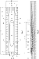
- Figures 1-3 schematically show a first embodiment of a (non-floating, stationary) dry dock (e.g. a "graving dock”) for building and/or dismantling a naval structure, for example a ship S.
- a dry dock e.g. a "graving dock”
- the dock includes a substantially horizontal floor 1 that is located below a predetermined horizontal dock top level G2 (see Fig. 3 ).
- the dock includes two opposite longitudinal side walls 3, a lateral (front) side wall 5 having a closable access 9, and a lateral (back) side wall 4, said side walls 3, 4, 5 extending from the floor to the dock's top level G2.
- Said closable access 9 provides access to the dock's inner space from a water environment, for example river water or sea water, having a predetermined water level.
- a water environment for example river water or sea water
- the opposite lateral side wall 4 provides access to the dock's interior from a respective on-shore location P that is above the predetermined water level.
- the closable access 9 can be configured in various ways, including e.g. a concrete dock gate construction having one or more movable doors for closing and opening a respective passageway, as will be appreciated by the skilled person.
- the afore-mentioned predetermined water level may e.g. periodically vary between a low water level LW and a high water level HW, as is indicated in Fig. 2 .
- the upper surface of the concrete bottom 1 is arranged on a level that is below the predetermined water level, for example several meters below a said low water level LW in case of periodic water level variation.
- the upper surface of the concrete bottom 1 is arranged on a level that is about 5 to 6 meters (e.g. about 5.5 meter) below a said high water HW, in case of periodic water level variation.
- the dock entrance/gate 9 can be provided with a local concrete floor 9a that protrudes upwardly with respect to top surface of the main floor 1, e.g. by a distance of about 1 to 2 meters (particularly a distance of about 1.5 meters).
- the dock is designed for accommodating relatively large vessels S.
- the substantially concrete floor 1 as such has a length L1 of at least about 200 meters, and preferably a length in the range of about 250 to 400 meters (for example a length L1 of about 300 meters).
- the concrete floor 1 can have width W1 of at least about 35 meters, and preferably a width W1 in the range of about 40 to 75 meters (for example a width W2 of about 50 meters).
- the dock has been partly made in an excavation (pit, dugout) that has been made on-site, in the ground K.
- the main floor 1 is made of reinforced/armoured concrete (the concrete including e.g. steel reinforcement bars, grids and/or webbings).
- a thickness of the concrete floor can e.g. be about 0.5 meter or about 1 meter.
- the substantially horizontal floor 1 can be a concrete floor having a pile foundation 14 (e.g. existing of a grid of concrete piles extending normally -vertically- below the floor 1).
- a primary stabilisation 13 layer (or layers), for example including or consisting of sand, extending below the concrete floor 1.
- the primary stabilisation 13 layer (or layers) is/are laid in an aforementioned excavation.
- the foundation piles 14 extend through the at least one primary stabilisation layer, and into a lower section of the ground K, to provide a durable and stable support for the massive dock floor 1.
- Figure 4 shows an alternative further advantageous example, that does not include a pile foundation.
- At least the two opposite longitudinal dock side walls 3 include a gentle slope (see particularly Fig. 3 ). It has been found that a resulting stable and durable dock can be constructed in a relatively inexpensive way, particularly because the side walls do not have to be vertical side walls anymore.
- the two lateral side walls 4, 5 are provided with such slanted surfaces, along respective gentle slopes (see Fig. 1, 2 ). Slanted surfaces in the front lateral side wall 5 e.g. extend next to the gate 9 (e.g. at opposite sides) in that wall 5, see Fig. 1 .
- a slope of the lateral back side wall 4 is significantly smaller than the slopes of the longitudinal side walls 3 (the lateral back side wall 4 for example having a maximum slope angle that is 50% of the slope angle ⁇ of longitudinal side walls, for example a maximum slope angle of about 10 degrees, and for example a minimum slope angle of 1 degrees), allowing transport of naval structure parts into or out of the dock using transport means (e.g. rollable supporting carriers, transport vehicles, trains, trucks or the-like).
- transport means e.g. rollable supporting carriers, transport vehicles, trains, trucks or the-like.
- the bottom of the lateral (slanted) back side wall 4 may be provided with a slanted concrete floor 11 for supporting heavy loads, such as carriers transporting naval structure part out or (or into) the dock.
- a horizontal length L2 of the lateral back side wall 4 (measured in parallel with the dock's central line) can e.g. be in the range of about 50 to 100 meters, for example a range of 60 to 80 meters, for example about 75 meters.
- both longitudinal side walls 3 are fully slanted, providing upwardly facing slanted surfaces with gentle slopes.
- the slanted upper surface of each at least partly slanted longitudinal side wall 3 includes an angle ⁇ with a horizontal plane that is smaller than about 45 degrees, particularly smaller than about 30 degrees. More preferably, said angle ⁇ is smaller than about 20 degrees. Also, preferably, said angle ⁇ is larger than 10 degrees. For example, the angle ⁇ can be in the range of 15 to 20 degrees.
- both side walls 3 are provided with the same slope, however, that is not required.
- each longitudinal side wall 3 as such can be relatively wide, measured in horizontal direction.
- a width W2 of each slanted upper side of the side wall 3, measured horizontally from a point above a longitudinal edge of the bottom 1 of the dock to a longitudinal upper inner edge of that surface (i.e. at the top level G2) can be at least 20 meters, for example about 25 meters or more (a maximum width W2 e.g. being 50 meters).
- the longitudinal side wall 3 may be provided with an outer wall section, that is located above an outer section of an above-mentioned excavation in this example, the outer wall section having e.g. a width W3 in the range of about 10 to 40 meters, for example 20 to 30 meters.
- At least part of the dock can reside in an excavation in the ground K.
- an initial ground level (before the dock was constructed) is indicated by dashed line G1.
- a width W4 of the excavation (see e.g. Fig. 1 ) is significantly larger than the width W1 of the dock's bottom, for example by at least 50% and particularly by at least 90%.
- the width W4 of the excavation that receives a dock or dock part can e.g. be at least 50 meters, particularly at least 80 meters, for example about 100 meters.
- a maximum width of such an excavation can be e.g. 150 meters, or another maximum width (e.g. larger than 150 meters).
- a length L3 of said excavation can be the sum of the length L1 of the bottom 1 and the lengths of the two lateral side walls (measured in horizontal direction).
- the length L3 of said excavation can be more than 250, for example a length in the range of 300 to 500 meters (particularly a length in the range of about 450 to 450 meters, for example about 400 meters, or longer).
- the excavation as such can have a substantially horizontal upper side M (see Fig. 3 ) extending at a distance below the dock bottom 1 (with said primary stabilisation layer there-between).
- the excavation as such can substantially slanted upper sides N along lower sides of the two side walls 3.
- the top level G2 of the dock is located above the initial ground level G1.
- the dock is provided with (partly slanted) embankments, providing respective upper parts of all side walls 3, 4, 5.
- the at least partly slanted side walls 3 include embankments 3H that extend on top of an initial ground level G1, the embankments 3H preferably providing parts of the slanted inner dock sides (see Fig. 3 ).
- the two lateral side walls 4, 5 are provided with respective (partly slanted) embankment parts.
- each at least partly slanted longitudinal side wall 3 is defined by a fixation layer 12 (see Fig. 3, 4 ).
- the slanted upper surface of each at least partly slanted side walls 3 can be defined by a stabile layer 12 including one or more of rocks, rocklike elements, crushed stone, or a different type of layer 12.
- the fixation layers 12 at least extend from the level of the bottom 1 to the slanted sides of said embankment sections 3H.
- Longitudinal walls 19, for example made of (reinforced) concrete, may extend along the concrete bottom 1 for supporting lower longitudinal sides of said fixation layers 12.
- Slanted sections of the lateral walls 4, 5 may be configured in a similar manner, with respective fixation layers 12 and respective lower supporting walls.
- the dock is provided with a water-impervious structure 3a, 1, 11, 3a' that extends uninterruptedly over the entire area of the dry dock (along both longitudinal and lateral dock directions), in said side walls and through or below the substantially horizontal floor.
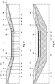
- the longitudinal side walls 3 as such contain respective water-impervious layers 3a (see Fig. 3 ), providing ground water barrier layers.
- these layers 3a are part of said water-impervious structure.
- each said water-impervious layer 3a of a respective side wall substantially extends along a respective gentle slope.
- the lateral side walls 4, 5 are provided with such respective water-impervious layers as well.
- the back lateral side wall 4 is preferably provided with a concrete bottom 11, which concrete bottom 11 as such can provide at least part of a respective water-impervious layer of that wall 4.
- the front lateral side wall 5 is provided with the dock gate 9, so that a respective water-impervious layer is provided in front side wall sections that are located next to the dock gate (in the case that the dock gate does not take up all the space of that front wall 5).
- the water-impervious layers 3a are connected to the concrete bottom 1 in a continuously water-tight manner (for example directly, or indirectly using suitable connection or intermediate sealing means), and extend through the respective side walls to a level at or close to the top level G2 of the dock. Moreover, as follows from Fig. 3 , the water-impervious layers 3a of this embodiment, extend to a level above said initial ground level G1, and to locations in said embankment sections 3H, laterally externally with respect of the excavation that contains part of the dock.
- a water-impervious layer (if any) of the lateral back side wall 4 can be connected to a respective concrete bottom 11 in a continuously water tight manner (for example directly, or indirectly using suitable connection or sealing means), and extend through the respective side walls to a level at or close to the top level G2 of the dock.
- a water-impervious layer (if any) of the lateral front side wall 5 can be connected to a respective dock gate structure in a continuously water tight manner (for example directly, or indirectly using suitable connection or sealing means), and extend through the respective side walls to a level at or close to the top level G2 of the dock.
- the various water-impervious layers and the concrete main bottom 1 (and optional concrete back side bottom 11) of the dock provide a water tight barrier, preventing ground water from penetrating into the dock's interior.
- the at least partly slanted side walls 3 at least include one first stabilizing layer 3b extending below the water-impervious layer 3a.
- the first stabilizing layer 3a is or includes a sand layer.
- this layer 3a can be sand layer, or a layer consisting of at least 50% sand and one or more other suitable building materials.
- the first stabilizing layer 3b extends on top of the slanted parts of the said excavation, and can provide a levelling function.
- the at least partly slanted side wall 3 can at least includes one second stabilizing layer 3c extending above the water-impervious layer 3a, particularly having a thickness (and respective weight) to press and hold the water-tight layer 3a in place, against possible pressure of ambient ground water.
- this layer 3a can be sand layer, or a layer consisting of at least 50% sand and one or more other suitable building materials.
- the second stabilizing layer 3c can be made of the same material or materials as the first stabilizing layer 3b.
- the water-impervious layer 3a as such can be made of a flexible material.
- the water-impervious layer 3a is a water impervious foil, for example a plastic foil.
- the impervious layers 3a may also be configured differently.
- the layer is provided with a number of local folds or be at least partly laid in a wave-like pattern, allowing flexing and/or deformation of the layer 3a, e.g. due to setting and/or resetting and/or local movement or nearby layers 3b, 3c.
- the dock is provided with a means for pumping water from the dock's interior.
- the concrete floor 1 can be provided with one or more drainage openings for draining water out of the dock.
- one or more pumps can be provide for pumping water out of the dock.
- Operation of the dock can involve dismantling a naval structure S.
- the dock's entrance 9 can be opened, allowing ambient water entering the dock (in case the dock is still empty), and allowing the naval structure S to enter the dock.
- this is carried out during a high water level period; in that case, once the naval structure S is inside the dock, part of the water can leave the dock via the dock's entrance 9 when the water level lowers to a respective low water level LW.
- the dock's entrance 9 can be closed, and any remaining water can be drained from the dock.
- the naval structure S is supported on the dock bottom 1 using intermediate supports.
- the naval structure S can be dismantled, wherein naval structure parts can be removed from the dock via the gently sloped exit side (i.e. the slanted floor 11 at the back side 4).
- the dry dock can be used for construction of a naval structure S.
- a major advantage of the dock is that it can be constructed in a relatively efficient manner, using overall relatively inexpensive building materials (for example sand). Construction can be carried out in the following manner.
- a said excavation can be made in the ground to receive a major part of the dock (except surrounding embankment parts, if any).
- the excavation can have a substantially rectangular shape, with the slanted sides N and substantially horizontal central side M.
- the excavation can be relatively large, as follows from the above (with an above-mentioned excavation length L3 and an excavation width W4).
- the concrete bottom 1 and side wall structures 3 can be provided.
- the concrete bottom 1 can be laid after the primary stabilisation 13 layer (or layers) has been laid, after the foundation piles 14 have been arranged into the ground and primary stabilisation 13 layer, and for example after the slanted side walls 3 (,4, 5) have been partly constructed.
- the concrete bottom 1 is preferably provided with reinforcement, and is preferably connected to adjoining water-impervious layers 3a in a water-tight manner.
- the side walls 3, 4, 5 are constructed as to have the gently sloped side along the dock's vessel receiving area.
- the side walls 3, 4, 5 can be constructed after the excavation has been provided, wherein the construction involves providing the first stabilization layers 3b on respective locations in the excavation (i.e. on the respective slanted bottom sections N), providing the least one water-impervious layer 3a (e.g. -but not limited to- a foil) over the respective first stabilization layers 3b, and subsequently constructing remaining parts 3c, 12, 3H of the side walls 3 above the respective water-impervious layer 3a.
- the method further includes constructing the embankments 3H to provide upper sections of the least partly slanted side walls 3.
- Figure 4 shows an alternative embodiment, which differs from the embodiment depicted in Fig. 3 in that the substantially horizontal floor 1 is a concrete floor without a pile foundation.
- the water-impervious layer 3a' also extends at a level below the substantially horizontal floor 1.
- a single water-impervious layer 3a' is provided, extending within the longitudinal side walls 3' and extending below the central bottom section 1 of the dock.
- the embodiment depicted in Fig. 4 partly lies in a large excavation, having slanted sides N' and a substantially horizontal bottom side M', wherein at least one stabilisation layer 13' (for example consisting of sand, or sand in combination with one or more other building materials) has been laid.
- the water-impervious layer 3a' extends through that stabilisation layer 13' and providing a ground water barrier for the entire dock.
- a stabilizing layer section 13' extending above the water-impervious layer 3a' preferably has a thickness (and respective weight) to press and hold the water-tight layer 3a' in place, countering possible pressure of ambient ground water.
- any reference signs placed between parentheses shall not be construed as limiting the claim.
- the word 'comprising' does not exclude the presence of other features or steps then those listed in a claim.
- the words 'a' and 'an' shall not be construed as limited to 'only one', but instead are used to mean 'at least one', and do not exclude a plurality.
- the mere fact that certain measures are recited in mutually different claims does not indicate that a combination of these measures cannot be used to advantage.
- the above-mentioned dock dimensions are merely exemplary embodiments of the invention.
- Dock lengths and widths can be larger or smaller than afore-mentioned dimensions, depending e.g. on the type (and dimensions) of a naval structure that is to be received in the dock.
- stabilisation layers 3b, 3c, 13, 13' of the dock can include various materials, for example but not limited to sand.
- one or more of the stabilisation layers 3b, 3c, 13, 13' can include or substantially consist of clay containing soil.
- one or more of the stabilisation layers 3b, 3c, 13, 13' can include or substantially rock dump.
- one or more of the stabilisation layers 3b, 3c, 13, 13' can include or substantially consist of crushed stone.
- one or more of the stabilisation layers 3b, 3c, 13, 13' can include or substantially consist of natural building material(s).
- each stabilisation layers 3b, 3c, 13, 13' can include or consist of a mixture of afore-mentioned materials, the materials including sand, clay containing soil, rock dump, and crushed stone.
- each stabilisation layers 3b, 3c, 13, 13' is configured such that it provides a stabile supporting layer for dock structure(s) extending above that layer.
Landscapes
- Engineering & Computer Science (AREA)
- Mechanical Engineering (AREA)
- Ocean & Marine Engineering (AREA)
- Processing Of Solid Wastes (AREA)
- Building Environments (AREA)
- Working Measures On Existing Buildindgs (AREA)
- Revetment (AREA)
- Buildings Adapted To Withstand Abnormal External Influences (AREA)
Claims (15)
- Trockendock zum Bauen und/oder Zerlegen einer Schiffsstruktur, umfassend einen im Wesentlichen horizontalen Boden (1), der sich unterhalb eines vorbestimmten oberen Niveaus (G2) befindet, Dockseitenwände (3, 4, 5), die sich von dem Boden bis zu dem oberen Niveau (G2) erstrecken, einen verschließbaren Zugang (9), der in einer Seitenwand (5) bereitgestellt ist, um eine Schiffsstruktur in das Dock zu bewegen, wobei zumindest zwei der Seitenwände (3, 4, 5) zumindest teilweise schräg sind und Folgendes aufweisen:- eine geringfügige Neigung; und- eine wasserundurchlässige Schicht (3a), insbesondere eine Grundwassersperrschicht; wobei eine schräge obere Fläche von jeder zumindest teilweise schrägen Seitenwand (3) einen Winkel (θ) mit einer horizontalen Ebene beinhaltet, der kleiner ist als ungefähr 45 Grad, insbesondere kleiner als 30 Grad;wobei die zumindest teilweise schräge Seitenwand (3) zumindest eine erste Stabilisierungsschicht (3b) beinhaltet, die sich unterhalb der wasserundurchlässigen Schicht (3a) erstreckt; und wobei die zumindest teilweise schräge Seitenwand (3) zumindest eine zweite Stabilisierungsschicht (3c) beinhaltet, die sich oberhalb der wasserundurchlässigen Schicht (3a) erstreckt.
- Dock nach Anspruch 1, wobei zumindest zwei gegenüberliegende längsgerichtete Dockseitenwände (3) die geringfügige Neigung und eine jeweilige wasserundurchlässige Schicht (3a) beinhalten.
- Dock nach einem der vorstehenden Ansprüche, wobei eine schräge obere Fläche einer zumindest teilweise schrägen Seitenwand (3) einen Winkel (Θ) mit einer horizontalen Ebene beinhaltet, der kleiner ist als 20 Grad, und insbesondere einen Winkel, der größer ist als 1 Grad, beispielsweise einen Winkel in dem Bereich von 15 bis 20 Grad.
- Dock nach einem der vorstehenden Ansprüche, wobei die erste Stabilisierungsschicht eine Sandschicht ist oder diese beinhaltet.
- Dock nach einem der vorstehenden Ansprüche, wobei die zweite Stabilisierungsschicht aus demselben Material oder denselben Materialien wie die erste Stabilisierungsschicht ist.
- Dock nach einem der vorstehenden Ansprüche, wobei eine schräge obere Fläche von jeder zumindest teilweise schrägen Seitenwand (3) durch eine Fixierungsschicht definiert ist, wobei die schräge obere Fläche von jeder zumindest teilweise schrägen Seitenwand (3) durch eine stabile Schicht definiert ist, die eines oder mehrere von Steinen, steinartigen Elementen oder Schotter beinhaltet.
- Dock nach einem der vorstehenden Ansprüche, wobei die wasserundurchlässige Schicht (3a) aus einem flexiblen Material hergestellt ist.
- Dock nach einem der vorstehenden Ansprüche, wobei die wasserundurchlässige Schicht (3a) eine wasserundurchlässige Folie ist.
- Dock nach einem der vorstehenden Ansprüche, wobei der im Wesentlichen horizontale Boden (1) ein wasserdichter Boden ist, beispielsweise ein Betonboden, wobei die zumindest eine wasserundurchlässige Schicht (3a) auf eine kontinuierliche wasserdichte Weise, beispielsweise direkt oder indirekt, mit dem Boden (1) verbunden ist.
- Dock nach einem der vorstehenden Ansprüche, wobei sich die wasserundurchlässige Schicht (3a) auch auf einem Niveau unterhalb des im Wesentlichen horizontalen Bodens (1) erstreckt.
- Dock nach einem der vorstehenden Ansprüche, wobei zumindest ein Teil des Docks in einem Aushub in dem Boden residiert, wobei der Aushub vorzugsweise zumindest eine im Wesentlichen schräge Oberseite zum Definieren einer Unterseite einer jeweiligen zumindest teilweise schrägen Seitenwand aufweist; wobei sich das obere Niveau (G2) des Docks oberhalb eines Bodenniveaus (G1) befindet; und wobei die zumindest teilweise schrägen Seitenwände (3) Dämme beinhalten, wobei die Dämme vorzugsweise schräge innere Dockseiten aufweisen.
- Verfahren zum Bauen eines Trockendocks, beispielsweise eines Docks nach einem der vorstehenden Ansprüche, wobei das Verfahren in beliebiger Reihenfolge Folgendes umfasst:- Bereitstellen eines im Wesentlichen horizontalen Bodens (1);- Bereitstellen von Dockseitenwänden (3, 4, 5);- Bereitstellen eines verschließbaren Zugangs (9) in einer Seitenwand (5),wobei zumindest zwei der Seitenwände (3, 4, 5) konstruiert sind, um eine geringfügig geneigte Seite entlang eines Schiffsaufnahmebereichs des Docks aufweisen, und mit einer wasserundurchlässigen Schicht (3a) versehen sind;
wobei eine schräge obere Fläche von jeder zumindest teilweise schrägen Seitenwand einen Winkel (θ) mit einer horizontalen Ebene beinhaltet, der kleiner ist als ungefähr 45 Grad; und
wobei die zumindest teilweise schrägen Seitenwände zumindest eine erste Stabilisierungsschicht (3b), die sich unterhalb der wasserundurchlässigen Schicht (3a) erstreckt und eine zweite Stabilisierungsschicht (3c), die sich unterhalb der wasserundurchlässigen Schicht (3a) erstreckt, beinhalten. - Verfahren nach Anspruch 12, das Folgendes beinhaltet:- Ausheben eines Dock-Aufnahmehohlraums, und optional Bereitstellen von zumindest einer Grundschicht (13) in dem Hohlraum;- Bereitstellen der zumindest einen wasserundurchlässigen Schicht der Seitenwände entlang zumindest eines Seitenwandteils einer Unterseite des Hohlraums oder der entsprechenden optionalen Grundschicht;- Bauen von übrigen Teilen der Seitenwände oberhalb der jeweiligen wasserundurchlässigen Schicht;- Bereitstellen zumindest eines unteren Abschnitts der wasserundurchlässigen Schicht entlang zumindest eines unteren Teils der Unterseite des Hohlraums oder der jeweiligen optionalen Grundschicht; und- Bauen des im Wesentlichen horizontalen Bodens (1) auf einem Niveau oberhalb des unteren Abschnitts der wasserundurchlässigen Schicht, vorzugsweise mit einer Fundamentschicht zwischen dem Boden (1) und der wasserundurchlässigen Schicht.
- Verfahren nach einem der Ansprüche 12-13, das Folgendes beinhaltet:
Bauen von Dämmen, um obere Abschnitte der zumindest teilweise schrägen Seitenwände bereitzustellen. - Verfahren nach einem der Ansprüche 12-14, das Folgendes beinhaltet:
Verbinden der wasserundurchlässigen Schicht (3a) auf eine kontinuierlich wasserdichte Weise mit angrenzenden Strukturen des Docks (1, 9, 11), beispielsweise durch eine direkte wasserdichte Verbindung oder durch eine zwischenliegende wasserdichte Verbindungs- oder Dichtungseinrichtung.
Priority Applications (2)
| Application Number | Priority Date | Filing Date | Title |
|---|---|---|---|
| SI201730446T SI3408170T1 (sl) | 2016-01-27 | 2017-01-26 | Suhi dok za izgradnjo in/ali razstavljanje pomorskih zgradb |
| HRP20201587TT HRP20201587T1 (hr) | 2016-01-27 | 2017-01-26 | Suho pristanište za izgradnju i/ili demontažu brodskih konstrukcija |
Applications Claiming Priority (2)
| Application Number | Priority Date | Filing Date | Title |
|---|---|---|---|
| NL2016167A NL2016167B1 (en) | 2016-01-27 | 2016-01-27 | Dry dock for building and/or dismantling navel structures. |
| PCT/NL2017/050050 WO2017131518A1 (en) | 2016-01-27 | 2017-01-26 | Dry dock for building and/or dismantling navel structures |
Publications (2)
| Publication Number | Publication Date |
|---|---|
| EP3408170A1 EP3408170A1 (de) | 2018-12-05 |
| EP3408170B1 true EP3408170B1 (de) | 2020-07-08 |
Family
ID=58094479
Family Applications (1)
| Application Number | Title | Priority Date | Filing Date |
|---|---|---|---|
| EP17706322.9A Active EP3408170B1 (de) | 2016-01-27 | 2017-01-26 | Trockendock zum bau und/oder zu demontage von kettenkastenstrukturen |
Country Status (13)
| Country | Link |
|---|---|
| US (1) | US10913520B2 (de) |
| EP (1) | EP3408170B1 (de) |
| CY (1) | CY1123446T1 (de) |
| DK (1) | DK3408170T3 (de) |
| ES (1) | ES2823174T3 (de) |
| HR (1) | HRP20201587T1 (de) |
| LT (1) | LT3408170T (de) |
| MY (1) | MY197035A (de) |
| NL (1) | NL2016167B1 (de) |
| PH (1) | PH12018550121A1 (de) |
| PT (1) | PT3408170T (de) |
| SI (1) | SI3408170T1 (de) |
| WO (1) | WO2017131518A1 (de) |
Families Citing this family (2)
| Publication number | Priority date | Publication date | Assignee | Title |
|---|---|---|---|---|
| CN112726673B (zh) * | 2020-12-24 | 2022-10-04 | 中交第四航务工程局有限公司 | 坞门浮运出坞安装的施工方法 |
| CN112726672B (zh) * | 2020-12-24 | 2022-10-04 | 中交第四航务工程局有限公司 | 坞门浮运进坞寄放的施工方法 |
Family Cites Families (10)
| Publication number | Priority date | Publication date | Assignee | Title |
|---|---|---|---|---|
| US472566A (en) * | 1892-04-12 | von nerta | ||
| US136560A (en) * | 1873-03-04 | Improvement in building docks | ||
| US561458A (en) * | 1896-06-02 | walsh | ||
| US471805A (en) * | 1892-03-29 | simpson | ||
| US2338110A (en) * | 1940-12-09 | 1944-01-04 | Frederic R Harris | Graving dry dock and method of construction |
| US3252155A (en) * | 1962-05-18 | 1966-05-17 | American Potash & Chem Corp | Liquid receptacle and method for preparing same |
| US3377810A (en) * | 1966-02-09 | 1968-04-16 | Ernest W. Crumley | Pumping apparatus for drydock and caisson |
| NO832105L (no) * | 1983-06-09 | 1985-01-07 | Selvaagbygg, A/S, | Fremgangsmaate ved dokking av en flytende konstruksjon |
| GB9610767D0 (en) * | 1996-05-23 | 1996-07-31 | Dobson James K | Dry docking pontoon |
| NL2008291C2 (nl) * | 2011-07-13 | 2013-05-08 | Desso Sports Systems N V | Onderbouw voor een kunstgrasveld. |
-
2016
- 2016-01-27 NL NL2016167A patent/NL2016167B1/en active
-
2017
- 2017-01-26 US US16/072,903 patent/US10913520B2/en active Active
- 2017-01-26 MY MYPI2018702647A patent/MY197035A/en unknown
- 2017-01-26 ES ES17706322T patent/ES2823174T3/es active Active
- 2017-01-26 PT PT177063229T patent/PT3408170T/pt unknown
- 2017-01-26 EP EP17706322.9A patent/EP3408170B1/de active Active
- 2017-01-26 DK DK17706322.9T patent/DK3408170T3/da active
- 2017-01-26 LT LTEP17706322.9T patent/LT3408170T/lt unknown
- 2017-01-26 HR HRP20201587TT patent/HRP20201587T1/hr unknown
- 2017-01-26 WO PCT/NL2017/050050 patent/WO2017131518A1/en not_active Ceased
- 2017-01-26 SI SI201730446T patent/SI3408170T1/sl unknown
-
2018
- 2018-07-26 PH PH12018550121A patent/PH12018550121A1/en unknown
-
2020
- 2020-10-06 CY CY20201100938T patent/CY1123446T1/el unknown
Non-Patent Citations (1)
| Title |
|---|
| None * |
Also Published As
| Publication number | Publication date |
|---|---|
| SI3408170T1 (sl) | 2020-12-31 |
| ES2823174T3 (es) | 2021-05-06 |
| CY1123446T1 (el) | 2021-12-31 |
| NL2016167B1 (en) | 2017-08-01 |
| MY197035A (en) | 2023-05-22 |
| DK3408170T3 (da) | 2020-10-12 |
| LT3408170T (lt) | 2020-12-28 |
| PH12018550121A1 (en) | 2019-03-18 |
| US10913520B2 (en) | 2021-02-09 |
| PT3408170T (pt) | 2020-10-15 |
| WO2017131518A1 (en) | 2017-08-03 |
| US20190002066A1 (en) | 2019-01-03 |
| HRP20201587T1 (hr) | 2020-12-11 |
| EP3408170A1 (de) | 2018-12-05 |
Similar Documents
| Publication | Publication Date | Title |
|---|---|---|
| US7708495B1 (en) | Levee system | |
| US7651298B2 (en) | Flood levee and barrier module and system | |
| US7744310B2 (en) | Hydrostatically operated variable height bulkhead | |
| US8177457B2 (en) | Pipeline protection and levee module system | |
| US4045965A (en) | Quay structure | |
| US20080240861A1 (en) | Prefabricated levee apparatus and system | |
| WO2013114134A2 (en) | Floatable constructions | |
| CN114787466A (zh) | 具备防洪水围墙的防水灾设施 | |
| EP3408170B1 (de) | Trockendock zum bau und/oder zu demontage von kettenkastenstrukturen | |
| HK40001490B (en) | Dry dock for building and/or dismantling navel structures | |
| HK40001490A (en) | Dry dock for building and/or dismantling navel structures | |
| US20110033242A1 (en) | Modular-unit floodwall system | |
| JP7285392B2 (ja) | L型ケーソン構造 | |
| JP7389893B2 (ja) | 海上構造及び建設方法 | |
| JP6659489B2 (ja) | 防波構造物 | |
| JP4611123B2 (ja) | 廃棄物処分場 | |
| RU2229553C1 (ru) | Модуль берегового защитного сооружения | |
| JP5427867B2 (ja) | 津波対策用岸辺構造 | |
| RU2243319C2 (ru) | Модуль берегового защитного сооружения | |
| EP1355010A1 (de) | Verfahren zur Errichtung einer provisorischen Hochwasserschutzwand | |
| RU79114U1 (ru) | Водоналивная наращиваемая дамба от наводнений | |
| JP4776694B2 (ja) | 港湾構造物及びこのような構造物の建設方法 | |
| EP4677156A1 (de) | Wasserdämmvorrichtung mit einem schwimmenden wasserdämmkörper, verwendung einer solchen wasserdämmvorrichtung und schwimmender wasserdämmkörper für eine solche wasserdämmvorrichtung | |
| GB2571719A (en) | Foundation system | |
| CN208533619U (zh) | 一种火力发电厂一体式排水口结构 |
Legal Events
| Date | Code | Title | Description |
|---|---|---|---|
| STAA | Information on the status of an ep patent application or granted ep patent |
Free format text: STATUS: UNKNOWN |
|
| STAA | Information on the status of an ep patent application or granted ep patent |
Free format text: STATUS: THE INTERNATIONAL PUBLICATION HAS BEEN MADE |
|
| PUAI | Public reference made under article 153(3) epc to a published international application that has entered the european phase |
Free format text: ORIGINAL CODE: 0009012 |
|
| STAA | Information on the status of an ep patent application or granted ep patent |
Free format text: STATUS: REQUEST FOR EXAMINATION WAS MADE |
|
| 17P | Request for examination filed |
Effective date: 20180807 |
|
| AK | Designated contracting states |
Kind code of ref document: A1 Designated state(s): AL AT BE BG CH CY CZ DE DK EE ES FI FR GB GR HR HU IE IS IT LI LT LU LV MC MK MT NL NO PL PT RO RS SE SI SK SM TR |
|
| AX | Request for extension of the european patent |
Extension state: BA ME |
|
| DAV | Request for validation of the european patent (deleted) | ||
| DAX | Request for extension of the european patent (deleted) | ||
| GRAP | Despatch of communication of intention to grant a patent |
Free format text: ORIGINAL CODE: EPIDOSNIGR1 |
|
| STAA | Information on the status of an ep patent application or granted ep patent |
Free format text: STATUS: GRANT OF PATENT IS INTENDED |
|
| REG | Reference to a national code |
Ref country code: HK Ref legal event code: DE Ref document number: 40001490 Country of ref document: HK |
|
| INTG | Intention to grant announced |
Effective date: 20200206 |
|
| GRAS | Grant fee paid |
Free format text: ORIGINAL CODE: EPIDOSNIGR3 |
|
| GRAA | (expected) grant |
Free format text: ORIGINAL CODE: 0009210 |
|
| STAA | Information on the status of an ep patent application or granted ep patent |
Free format text: STATUS: THE PATENT HAS BEEN GRANTED |
|
| AK | Designated contracting states |
Kind code of ref document: B1 Designated state(s): AL AT BE BG CH CY CZ DE DK EE ES FI FR GB GR HR HU IE IS IT LI LT LU LV MC MK MT NL NO PL PT RO RS SE SI SK SM TR |
|
| REG | Reference to a national code |
Ref country code: AT Ref legal event code: REF Ref document number: 1288173 Country of ref document: AT Kind code of ref document: T Effective date: 20200715 Ref country code: CH Ref legal event code: EP |
|
| REG | Reference to a national code |
Ref country code: DE Ref legal event code: R096 Ref document number: 602017019343 Country of ref document: DE |
|
| REG | Reference to a national code |
Ref country code: IE Ref legal event code: FG4D |
|
| REG | Reference to a national code |
Ref country code: HR Ref legal event code: TUEP Ref document number: P20201587 Country of ref document: HR |
|
| REG | Reference to a national code |
Ref country code: DK Ref legal event code: T3 Effective date: 20201007 Ref country code: FI Ref legal event code: FGE |
|
| REG | Reference to a national code |
Ref country code: PT Ref legal event code: SC4A Ref document number: 3408170 Country of ref document: PT Date of ref document: 20201015 Kind code of ref document: T Free format text: AVAILABILITY OF NATIONAL TRANSLATION Effective date: 20201006 |
|
| REG | Reference to a national code |
Ref country code: SE Ref legal event code: TRGR |
|
| REG | Reference to a national code |
Ref country code: NO Ref legal event code: T2 Effective date: 20200708 |
|
| REG | Reference to a national code |
Ref country code: HR Ref legal event code: T1PR Ref document number: P20201587 Country of ref document: HR |
|
| REG | Reference to a national code |
Ref country code: GR Ref legal event code: EP Ref document number: 20200402775 Country of ref document: GR Effective date: 20201116 |
|
| REG | Reference to a national code |
Ref country code: AT Ref legal event code: MK05 Ref document number: 1288173 Country of ref document: AT Kind code of ref document: T Effective date: 20200708 Ref country code: EE Ref legal event code: FG4A Ref document number: E019925 Country of ref document: EE Effective date: 20201008 |
|
| REG | Reference to a national code |
Ref country code: NL Ref legal event code: MP Effective date: 20200708 |
|
| PG25 | Lapsed in a contracting state [announced via postgrant information from national office to epo] |
Ref country code: AT Free format text: LAPSE BECAUSE OF FAILURE TO SUBMIT A TRANSLATION OF THE DESCRIPTION OR TO PAY THE FEE WITHIN THE PRESCRIBED TIME-LIMIT Effective date: 20200708 |
|
| REG | Reference to a national code |
Ref country code: HR Ref legal event code: ODRP Ref document number: P20201587 Country of ref document: HR Payment date: 20210126 Year of fee payment: 5 |
|
| PG25 | Lapsed in a contracting state [announced via postgrant information from national office to epo] |
Ref country code: RS Free format text: LAPSE BECAUSE OF FAILURE TO SUBMIT A TRANSLATION OF THE DESCRIPTION OR TO PAY THE FEE WITHIN THE PRESCRIBED TIME-LIMIT Effective date: 20200708 |
|
| PG25 | Lapsed in a contracting state [announced via postgrant information from national office to epo] |
Ref country code: NL Free format text: LAPSE BECAUSE OF FAILURE TO SUBMIT A TRANSLATION OF THE DESCRIPTION OR TO PAY THE FEE WITHIN THE PRESCRIBED TIME-LIMIT Effective date: 20200708 |
|
| REG | Reference to a national code |
Ref country code: DE Ref legal event code: R097 Ref document number: 602017019343 Country of ref document: DE |
|
| PG25 | Lapsed in a contracting state [announced via postgrant information from national office to epo] |
Ref country code: SM Free format text: LAPSE BECAUSE OF FAILURE TO SUBMIT A TRANSLATION OF THE DESCRIPTION OR TO PAY THE FEE WITHIN THE PRESCRIBED TIME-LIMIT Effective date: 20200708 Ref country code: CZ Free format text: LAPSE BECAUSE OF FAILURE TO SUBMIT A TRANSLATION OF THE DESCRIPTION OR TO PAY THE FEE WITHIN THE PRESCRIBED TIME-LIMIT Effective date: 20200708 |
|
| REG | Reference to a national code |
Ref country code: ES Ref legal event code: FG2A Ref document number: 2823174 Country of ref document: ES Kind code of ref document: T3 Effective date: 20210506 |
|
| PLBE | No opposition filed within time limit |
Free format text: ORIGINAL CODE: 0009261 |
|
| STAA | Information on the status of an ep patent application or granted ep patent |
Free format text: STATUS: NO OPPOSITION FILED WITHIN TIME LIMIT |
|
| PGFP | Annual fee paid to national office [announced via postgrant information from national office to epo] |
Ref country code: IS Payment date: 20210215 Year of fee payment: 5 |
|
| 26N | No opposition filed |
Effective date: 20210409 |
|
| PG25 | Lapsed in a contracting state [announced via postgrant information from national office to epo] |
Ref country code: SK Free format text: LAPSE BECAUSE OF FAILURE TO SUBMIT A TRANSLATION OF THE DESCRIPTION OR TO PAY THE FEE WITHIN THE PRESCRIBED TIME-LIMIT Effective date: 20200708 |
|
| REG | Reference to a national code |
Ref country code: EE Ref legal event code: MM4A Ref document number: E019925 Country of ref document: EE Effective date: 20210131 |
|
| PG25 | Lapsed in a contracting state [announced via postgrant information from national office to epo] |
Ref country code: MC Free format text: LAPSE BECAUSE OF FAILURE TO SUBMIT A TRANSLATION OF THE DESCRIPTION OR TO PAY THE FEE WITHIN THE PRESCRIBED TIME-LIMIT Effective date: 20200708 |
|
| REG | Reference to a national code |
Ref country code: CH Ref legal event code: PL |
|
| PG25 | Lapsed in a contracting state [announced via postgrant information from national office to epo] |
Ref country code: LU Free format text: LAPSE BECAUSE OF NON-PAYMENT OF DUE FEES Effective date: 20210126 |
|
| PG25 | Lapsed in a contracting state [announced via postgrant information from national office to epo] |
Ref country code: EE Free format text: LAPSE BECAUSE OF NON-PAYMENT OF DUE FEES Effective date: 20210131 |
|
| PG25 | Lapsed in a contracting state [announced via postgrant information from national office to epo] |
Ref country code: CH Free format text: LAPSE BECAUSE OF NON-PAYMENT OF DUE FEES Effective date: 20210131 Ref country code: LI Free format text: LAPSE BECAUSE OF NON-PAYMENT OF DUE FEES Effective date: 20210131 |
|
| REG | Reference to a national code |
Ref country code: EE Ref legal event code: TH4A Ref document number: E019925 Country of ref document: EE |
|
| REG | Reference to a national code |
Ref country code: HR Ref legal event code: ODRP Ref document number: P20201587 Country of ref document: HR Payment date: 20220124 Year of fee payment: 6 |
|
| REG | Reference to a national code |
Ref country code: HR Ref legal event code: ODRP Ref document number: P20201587 Country of ref document: HR Payment date: 20230126 Year of fee payment: 7 |
|
| PG25 | Lapsed in a contracting state [announced via postgrant information from national office to epo] |
Ref country code: HU Free format text: LAPSE BECAUSE OF FAILURE TO SUBMIT A TRANSLATION OF THE DESCRIPTION OR TO PAY THE FEE WITHIN THE PRESCRIBED TIME-LIMIT; INVALID AB INITIO Effective date: 20170126 |
|
| REG | Reference to a national code |
Ref country code: HR Ref legal event code: ODRP Ref document number: P20201587 Country of ref document: HR Payment date: 20240125 Year of fee payment: 8 |
|
| REG | Reference to a national code |
Ref country code: HR Ref legal event code: ODRP Ref document number: P20201587 Country of ref document: HR Payment date: 20250115 Year of fee payment: 9 |
|
| PGFP | Annual fee paid to national office [announced via postgrant information from national office to epo] |
Ref country code: DE Payment date: 20250116 Year of fee payment: 9 Ref country code: HR Payment date: 20250115 Year of fee payment: 9 |
|
| PGFP | Annual fee paid to national office [announced via postgrant information from national office to epo] |
Ref country code: DK Payment date: 20250123 Year of fee payment: 9 Ref country code: FI Payment date: 20250124 Year of fee payment: 9 Ref country code: RO Payment date: 20250121 Year of fee payment: 9 Ref country code: LT Payment date: 20250116 Year of fee payment: 9 |
|
| PGFP | Annual fee paid to national office [announced via postgrant information from national office to epo] |
Ref country code: BG Payment date: 20250115 Year of fee payment: 9 |
|
| PGFP | Annual fee paid to national office [announced via postgrant information from national office to epo] |
Ref country code: ES Payment date: 20250203 Year of fee payment: 9 |
|
| PGFP | Annual fee paid to national office [announced via postgrant information from national office to epo] |
Ref country code: IE Payment date: 20250123 Year of fee payment: 9 Ref country code: SE Payment date: 20250115 Year of fee payment: 9 |
|
| PGFP | Annual fee paid to national office [announced via postgrant information from national office to epo] |
Ref country code: NO Payment date: 20250124 Year of fee payment: 9 |
|
| PGFP | Annual fee paid to national office [announced via postgrant information from national office to epo] |
Ref country code: SI Payment date: 20250116 Year of fee payment: 9 Ref country code: BE Payment date: 20250116 Year of fee payment: 9 Ref country code: GR Payment date: 20250122 Year of fee payment: 9 Ref country code: LV Payment date: 20250116 Year of fee payment: 9 Ref country code: EE Payment date: 20250116 Year of fee payment: 9 |
|
| PGFP | Annual fee paid to national office [announced via postgrant information from national office to epo] |
Ref country code: FR Payment date: 20250123 Year of fee payment: 9 Ref country code: PL Payment date: 20250119 Year of fee payment: 9 |
|
| PGFP | Annual fee paid to national office [announced via postgrant information from national office to epo] |
Ref country code: IT Payment date: 20250127 Year of fee payment: 9 Ref country code: GB Payment date: 20250115 Year of fee payment: 9 |
|
| PGFP | Annual fee paid to national office [announced via postgrant information from national office to epo] |
Ref country code: TR Payment date: 20250116 Year of fee payment: 9 Ref country code: MT Payment date: 20250116 Year of fee payment: 9 |
|
| PGFP | Annual fee paid to national office [announced via postgrant information from national office to epo] |
Ref country code: AL Payment date: 20250122 Year of fee payment: 9 |
|
| PG25 | Lapsed in a contracting state [announced via postgrant information from national office to epo] |
Ref country code: PT Free format text: LAPSE BECAUSE OF NON-PAYMENT OF DUE FEES Effective date: 20250728 |
|
| PG25 | Lapsed in a contracting state [announced via postgrant information from national office to epo] |
Ref country code: IS Free format text: LAPSE BECAUSE OF NON-PAYMENT OF DUE FEES Effective date: 20220805 |
|
| PGFP | Annual fee paid to national office [announced via postgrant information from national office to epo] |
Ref country code: CY Payment date: 20250116 Year of fee payment: 9 |
|
| PG25 | Lapsed in a contracting state [announced via postgrant information from national office to epo] |
Ref country code: PT Free format text: LAPSE BECAUSE OF NON-PAYMENT OF DUE FEES Effective date: 20250728 |
|
| PGFP | Annual fee paid to national office [announced via postgrant information from national office to epo] |
Ref country code: PT Payment date: 20251219 Year of fee payment: 9 |
|
| PGRI | Patent reinstated in contracting state [announced from national office to epo] |
Ref country code: PT Effective date: 20251223 |