EP3408172B1 - Luftfahrzeugflügel mit einer beweglichen klappe und einem behälter zur unterbringung eines flexiblen schlauchs - Google Patents
Luftfahrzeugflügel mit einer beweglichen klappe und einem behälter zur unterbringung eines flexiblen schlauchs Download PDFInfo
- Publication number
- EP3408172B1 EP3408172B1 EP17701132.7A EP17701132A EP3408172B1 EP 3408172 B1 EP3408172 B1 EP 3408172B1 EP 17701132 A EP17701132 A EP 17701132A EP 3408172 B1 EP3408172 B1 EP 3408172B1
- Authority
- EP
- European Patent Office
- Prior art keywords
- rail
- wing
- housing
- guide rail
- box
- Prior art date
- Legal status (The legal status is an assumption and is not a legal conclusion. Google has not performed a legal analysis and makes no representation as to the accuracy of the status listed.)
- Active
Links
Images


Classifications
-
- B—PERFORMING OPERATIONS; TRANSPORTING
- B64—AIRCRAFT; AVIATION; COSMONAUTICS
- B64C—AEROPLANES; HELICOPTERS
- B64C9/00—Adjustable control surfaces or members, e.g. rudders
- B64C9/14—Adjustable control surfaces or members, e.g. rudders forming slots
- B64C9/22—Adjustable control surfaces or members, e.g. rudders forming slots at the front of the wing
-
- B—PERFORMING OPERATIONS; TRANSPORTING
- B64—AIRCRAFT; AVIATION; COSMONAUTICS
- B64D—EQUIPMENT FOR FITTING IN OR TO AIRCRAFT; FLIGHT SUITS; PARACHUTES; ARRANGEMENT OR MOUNTING OF POWER PLANTS OR PROPULSION TRANSMISSIONS IN AIRCRAFT
- B64D15/00—De-icing or preventing icing on exterior surfaces of aircraft
- B64D15/12—De-icing or preventing icing on exterior surfaces of aircraft by electric heating
-
- B—PERFORMING OPERATIONS; TRANSPORTING
- B64—AIRCRAFT; AVIATION; COSMONAUTICS
- B64C—AEROPLANES; HELICOPTERS
- B64C13/00—Control systems or transmitting systems for actuating flying-control surfaces, lift-increasing flaps, air brakes, or spoilers
- B64C13/24—Transmitting means
- B64C13/38—Transmitting means with power amplification
- B64C13/50—Transmitting means with power amplification using electrical energy
- B64C13/506—Transmitting means with power amplification using electrical energy overriding of personal controls; with automatic return to inoperative position
Definitions
- the invention relates to aircraft wings.
- the wing comprises a fixed central body and one or more movable leading edge flaps, each intended to be moved in rotation relative to the fixed central body.
- each of the two wings of the airfoil is generally equipped with mobile high-lift flaps located at the leading edge and at the trailing edge of the wing.
- the flaps are deployed for the landing and take-off phases in order to increase the lift at low or medium speed. Moreover, in flight and at cruising speed, the movable flaps are retracted to limit the resistance to the forward movement of the aircraft.
- each flap is carried out using guide rails, such as those known from the document EP 0 818 387 . These rails make it possible to move each movable leading edge flap along an arcuate path relative to the fixed central wing body, between a retracted position in which the flaps substantially match the fixed body, and a deployed position in which these flaps are moved forward.
- At least one of the movable shutters is electrically powered by cables which extend from the fixed central body.
- These cables are for example carried by a chain, known from the document EP 2 167 381 , which deploys between a retracted position, in which the movable shutter is retracted, and an unrolled position, in which the shutter is deployed.
- the documents US 2014/166835 , GB2417937 , EP2733064 describe aircraft wings having a fixed part and a movable part. They also show a cable connecting the mobile part to the fixed part.
- the chain has in particular a mass and a large size near the movable shutter.
- the invention aims to at least partially resolve the problems encountered in the solutions of the prior art.
- the invention relates to an aircraft wing.
- the wing comprises a fixed central body, a movable flap located at the periphery of the fixed central body and intended to be moved in rotation relative to the fixed central body between a retracted position and a deployed position, a flexible tubing comprising a first end connected to the body fixed central and a second end connected to the movable flap, and a guide rail of the movable flap and the flexible tubing.
- the rail is configured to move between a retracted position and an extended position, as the movable shutter moves from its retracted position to its deployed position.
- the wing further comprises a box for storing the flexible tubing, and a means for holding the flexible tubing.
- the box comprises a wall shaped so that the flexible tubing wraps around the box while being pressed against the wall, when the rail moves from its deployed position to its retracted position.
- the holding means is configured to hold the flexible tubing against or near the rail, the holding means being carried by the fixed central body.
- the flexible tubing runs along the rail, being attached to the rail near the distal end of the rail at which the rail is attached to the movable shutter.
- the case and the holding means advantageously allow the flexible tubing to accompany the movement of the shutter between its retracted position and its deployed position, along the rail.
- the tubing is then mechanically protected by the rail and the box.
- the mass and size of the wing near the movable flap are reduced due to the absence of a chain.
- the retainer, housing, and flexible tubing are also easy to install in the wing, and the tubing is easy to replace.
- the invention may optionally include one or more of the following features combined or not.
- the holding means comprises a pusher configured to hold the tubing against or near the rail, a fixing means configured to fix the pusher to the fixed central body, and preferably a return means urging the pusher in the direction of the rail.
- the holding means is closer to the proximal end of the rail, to which it is fixed to the fixed body, than to its distal end.
- the length of the periphery of the wall between an inlet of the box and an outlet of the box is substantially equal to the difference in length of the flexible tubing along the guide rail between the retracted position of the guide rail and its deployed position.
- the box comprises an inlet and / or an outlet shaped so as to guide the flexible tubing so that the tubing enters the box and / or leaves the box, in at least one predetermined direction.
- the inlet / outlet of the box comprises a deflector configured to deflect the flexible tubing in a predetermined direction.
- the box extends in a longitudinal direction which is inclined relative to the longitudinal direction of the guide rail.
- the housing extends in a longitudinal direction which is substantially parallel to the longitudinal direction of the guide rail.
- the box is made and / or positioned so as to avoid an accumulation of water, so as not to block and damage the tubing in the event of freezing.
- the wing comprises a second box for storing a second flexible tube, the second box comprising a wall shaped so that the second flexible tube is wound up in the box while being pressed. against the inner wall, when the guide rail moves from its extended position to its retracted position.
- the two flexible tubes extend along two opposite sides of the guide rail, the storage boxes each being located on one of the opposite sides of the guide rail.
- each flexible tubing comprises several cables and / or pipes joined together.
- each flexible tubing comprises an electric cable and / or a pneumatic pipe, the electric cable preferably supplying electric power to a defrosting system for the mobile shutter.
- the wing comprises an electrical connector rigidly secured to an external wall face delimiting the storage box, the first end of the flexible tubing being electrically connected to the electrical connector.
- the figure 1 shows an aircraft 1 having an airfoil 2 made up of a plurality of airfoil elements, also called aerodynamic bearing surfaces.
- front and rear are to be considered in relation to a direction of travel of the aircraft, this direction of travel being represented by arrow 3.
- wing elements of the aircraft there are two main wings 4, a vertical fin 6, as well as two horizontal stabilizers 7 located at the rear of this aircraft.
- these each comprise a fixed central wing body 8 and a leading edge 10.
- the fixed central body 8 is also referred to as the main central portion, this body constituting almost the entire wing, and being located behind the leading edge 10.
- XX the longitudinal direction of the leading edge, or also the direction of wingspan
- YY the direction oriented transversely with respect to the leading edge 10 of the wing 4
- ZZ the vertical direction
- the leading edge 10 of each of the wings 4 is equipped with at least one movable leading edge flap 16, this movable flap 16 being intended to move relative to the fixed central body 8.
- the movable leading edge flap 16 is shown schematically in a retracted position in which it follows the front part of the fixed central body 8 of the wing 4. In such a case, the movable flap 16 is in its position. more back.
- the flap 16 is of course designed to be moved between these two extreme positions, for example so as to make it adopt an intermediate take-off position, known to those skilled in the art.
- the movable flap 16 extends for example over substantially the entire length of the wing 4 in its direction of span XX or else only over part of the length of the wing 4 according to its direction of span XX.
- the flap 16 comprises an aerodynamic coating defining an intrados portion 24 as well as an extrados portion 26, the latter terminating in a trailing edge 27 of the shutter.
- the flap 16 is closed towards the rear by a closing covering 28, intended to match the fixed wing body 8 when it occupies the retracted position.
- the movable shutter 16 contains a defrosting system 17 which needs to be supplied electrically by cables, whether the shutter 16 is in the retracted position or in the deployed position. These cables are assembled and secured to each other within a tubing flexible 40 which extends from the fixed body 8 to the movable shutter 16.
- the flexible tubing 40 takes for example the form of a braid of electric cables 43.
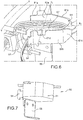
- the figure 3 shows a device for setting the movable leading edge flap 16 in motion, allowing the latter to pivot relative to the body 8, along an axis of rotation 18, between the fully deployed position and the retracted position.
- the device for setting in motion firstly comprises two drive rails 20 spaced from each other in the direction of span XX, these two rails 20 having a generally curved or circular shape, centered on the axis of rotation 18 of the shutter.
- each drive rail 20 is connected to the shutter 16 by a shutter fitting 25 projecting rearwardly from the closure covering 28, an additional connecting rod 29 being arranged between this same fitting 25 and a point rear end of the front end of the rail 20.
- the rails 20 are set in motion relative to the fixed body 8 by an actuating mechanism (not shown) which can take various forms known to those skilled in the art.
- This mechanism comprises, for example, a toothed wheel controlled by a rotating rack arm which is parallel to the axis of rotation 18.
- the device for setting the shutter in motion also comprises a follower rail 30 interposed between the two drive rails 20, preferably halfway between the latter, in the direction of span X-X.
- the follower rail 30 has a generally curved or circular arc shape in its longitudinal direction YY which corresponds substantially to the transverse direction of the wing 4. It extends from a proximal end 33 which is fixed to the fixed body 8 and a distal end 31 which is fixed to the movable flap 16.
- the follower rail 30 is movable between a retracted position and an extended position. It follows the movement of the drive rails 20 relative to the fixed central body 8, accompanying the movement of the shutter 16. It then forms a guide rail of the movable shutter 16 between its retracted position and its deployed position.
- the rail 30 In the deployed position, the rail 30 is located outside a protection box 39 and it is located more towards the front of the aircraft 1 than in the retracted position in which it is partially stored in the protection box 39.
- the rail has a curvilinear length Li outside the protection box 39 in the deployed position which is greater than its curvilinear length L 2 outside the protection box 39 in the retracted position.
- the difference in curvilinear length L 1 -L 2 of the rail outside the protection box 39 between its retracted position and its deployed position is substantially equal to the distance between the deployed position of the movable shutter 16 and its retracted position.
- the rail 30 also makes it possible to limit the amplitude of a slot between the trailing edge 27 of the shutter and the fixed body 8, in the deployed position of the movable shutter 16.
- the follower rail 30 carries the flexible tubing 40 outside the rail 30.
- the latter is in particular pressed against or at least held near one of the sides 32 of the rail 30 by a holding means 70 which will be described in detail. below.
- the flexible tubing 40 extends between a first end 45 to which it is connected to an electrical connector 49 and a second end 47 to which it is secured to the movable shutter 16 for electrically supplying the defrosting system 17.
- the electrical connector 49 is intended to be electrically connected to a complementary connector of the fixed body 8, being mechanically secured to the fixed body 8.
- the flexible tubing 40 runs along the rail 30 over substantially the entire length of the rail in its longitudinal direction Y-Y, from the retaining means 70 to the distal end 31 of the rail.
- the flexible tubing 40 extends close to the transverse median plane of the rail 30.
- the rail 30 then acts as a guide rail for the tubing 40.
- the flexible tubing 40 is fixed to the rail 30, near the distal end 31 of the rail, at the level of the fixing point 48. It is also kept close to the sidewall 32, near its first end 45 by a pusher 71. The flexible tubing 40 then follows the rail 30 all the better as it is substantially pressed against the rail 30, in particular near each of the ends 31, 33 of the rail when the rail 30 is in the deployed position.
- This pusher 71 has the general shape of a jaw traversed laterally on either side to allow the flexible tubing 40 to pass along the rail 30. It is for example made of a material comprising polytetrafluoroethylene, also known under the name of Teflon TM. .
- the pusher 71 slides along a rod 72 which is itself fixed at its first end to the fixed central body 8 and which is free at its second end. This rod 72 extends substantially transversely to the longitudinal direction Y-Y of the rail.
- the rod 72 comprises a return spring 73 between the pusher 71 and its second end.
- the return spring 73 biases the pusher 71 in the direction of the rail 30 so that it maintains the flexible tubing 40 sufficiently close to the sidewall 32. Since the spring 73 is offset from the middle of the pusher 71, the pusher 71 is also biased towards the rail 30 by a second spring 75 opposite the first spring 73 along the pusher 71.
- the pusher 71, the rod 72 and the spring 73 form part of the holding means 70 which is carried by the fixed central body 8 at the level of the rod 72.
- a storage box 50 is placed between the first end 45 of the tube and the pusher 71. It is located near the side 32 of the guide rail 30, on the same side of the rail 30 as the flexible tube 40. It is located in front of the protective box 39.
- the box 50 has a polygonal shape and it has a length along its longitudinal direction X 1 -X 1 which is close to its maximum thickness in a transverse direction Y 1 -Y 1 of the box 50.
- the length of the box 50 in its longitudinal direction X 1 -X 1 is approximately equal to 10 cm and approximately 10 cm along its transverse direction Y 1 -Y 1 .
- the longitudinal direction X 1 -X 1 of the box 50 is inclined at an angle ⁇ whose value is between 35 ° and 45 ° relative to the longitudinal direction YY of the rail.
- the inclination of the box 50 relative to the rail 30 makes it possible to limit the size of the box along the longitudinal direction YY of the rail.
- the box 50 is wider in its transverse direction Y 1 -Y 1 than the box 60 of the second embodiment.
- the storage box 50 comprises an inlet 51 for the flexible tubing 40, an outlet 53 for the flexible tubing 40, a wall 61 between the inlet 51 and the outlet 53, as well as a bottom 67, the wall 61 of which is rigidly attached. . It also includes a flange 55 for fixing the box 50 to the fixed body 8.
- the wall 61 is integral with the bottom 67.
- the fixing rim 55 is fixed to the wall 61.
- the wall 61 laterally delimits the housing 50. It comprises four wall elements 61a, 61b, 61c and 61d two by two adjacent.
- the first, second and fourth wall elements 61a, 61b and 61d are substantially planar.
- the third wall element 61c is curved, having an obtuse angle, which gives the housing 50 the general shape of a pentagon.
- the first wall element 61a is configured to deflect the part of the flexible tubing 40 located behind the pusher 71 in a predetermined direction, to bring it closer to the longitudinal direction X 1 -X 1 of the case.
- the wall 61 also comprises a deflector 54 at the level of the outlet 53 of the box, to deflect the flexible tube 40, so that the flexible tube 40 leaves the box with a direction which is substantially parallel to the longitudinal direction YY of the box. 50.
- the wall 61 has an internal face 52a and an external face 52b opposite to the internal face.
- the internal 52a and external 52b faces are substantially parallel to each other.
- the internal face 52a defines an internal contour of the case 50.
- the wall 61 is shaped so that the flexible tubing 40 is partially wound in the housing 50, in the retracted position of the rail 30, being pressed against the internal face 52a of the wall 61.
- the box 50 is shaped so that the difference in curvilinear length of the rail L 1 -L 2 outside the protection box 39 is substantially equal to the length of the periphery of the internal face 52a of the wall 61 Therefore, the flexible tubing 40 makes at most one turn of the wall 61 inside the housing 50, which limits the knots or the risks of catching the flexible tubing 40 when the rail 30 moves between the housing. retracted position and the deployed position and vice versa.
- the box 50 finally comprises a barrier 57 between the inlet 51 and the outlet 53 of the box and which is opposite to the wall 61.
- the barrier 57 forms a protuberance inside the box 50, which serves to retain the flexible tubing 40. , when the rail 30 is in the deployed position. It is also intended to constrain the flexible tubing 40 in height at the inlet 51 and / or at the outlet 53 of the housing 50 ..
- the rail 30 In the deployed position of the shutter 16, the rail 30 is in the deployed position.
- the flexible tubing 40 extends along the rail over substantially the entire length of the rail 30 in its longitudinal direction Y-Y, between the distal end 31 of the rail and the pusher 71.
- the portion of the flexible tubing 40 between the pusher 71 and the connector 49 passes through the inlet 51 of the box, runs along the barrier 57, and comes out through the outlet 53, so as to limit the length of the tube 40 in the box as much as possible. 50.
- the rail 30 In the retracted position of the shutter 16, the rail 30 is in the retracted position.
- a second portion 42 of fairly short length compared to the total length of the tubing 40 extends along the rail 30 in its longitudinal direction Y-Y, between the distal end 31 of the rail and the pusher 71.
- the first portion 41 of the flexible tubing 40 which is located between the pusher 71 and the connector 49, passes through the inlet 51 of the housing, along the internal face 52a of the wall 61 with which it is in mechanical contact over the entire periphery. from the box 50, and leaves through the outlet 53 at which it is deflected by the deflector 54.
- the retraction / deployment movement of the rail 30 modifies the length of flexible tubing 40 in the housing 50 but not the length of flexible tubing 40 at the outlet 53 of the housing 50, which remains substantially constant.
- the second embodiment which is shown in figure 8 , differs from the first embodiment in that it comprises two flexible tubes 44, 46 arranged respectively on each side of the rail 30, along one of the sides 32 of the rail, and two storage boxes 62, 64 which are each identical to that of the first embodiment described above, to store each of the flexible tubes 44, 46.
- the flexible tubes 44, 46 are substantially identical to those of the first embodiment. They are arranged symmetrically by plane symmetry with respect to a median longitudinal section plane of rail 30 which comprises the longitudinal direction Y-Y of rail 30.
- the first box 62 is oriented in a substantially identical manner to the storage box 50 of the first embodiment with respect to the rail 30.
- the first box 62 and the second box 64 are oriented substantially symmetrically by plane symmetry with respect to the longitudinal section plane of the rail 30.
- the figure 9 shows a third embodiment of the invention which differs from the first embodiment by the shape of the box 60 for storing the flexible tubing 40.
- the box 60 has a substantially parallelepipedal shape and it has a length along its longitudinal direction X 1 -X 1 which is significantly greater than that of its maximum thickness in a transverse direction Y 1 -Y 1 of the box 60 relative to the box 50 of the first embodiment.
- the length of the box 60 according to its longitudinal direction X 1 -X 1 is approximately equal to 5cm to 20cm that of the box 60 along its transverse direction Y 1 -Y 1 .
- the longitudinal direction X 1 -X 1 of the box 60 is parallel to the longitudinal direction YY of the rail 30. Since the box 60 is pressed against the side 32 of the rail and in view of the small thickness of the box 60, the longitudinal direction X 1 -X 1 of the box 60 and the longitudinal direction YY of the rail 30 are substantially coaxial.
- the lengthening of the box 60 in the longitudinal direction YY of the rail relative to that of the first embodiment makes it possible to limit its size in its transverse direction Y 1 -Y 1 , that is to say in the transverse direction of the rail .
- the storage box 60 has an inlet for the flexible tubing 40, an outlet for the flexible tubing 40, a wall 63 between the inlet and the outlet.
- the inlet and outlet of the box 60 are located opposite the pusher 71, they are substantially coincident, being only offset from one another according to the height of the box 60.
- the box also includes a flange 65 for fixing the box 60 with fixed body 8.
- the wall 63 is in one piece.
- the fixing rim 65 is fixed to the wall 63.
- the wall 63 laterally delimits the housing 60. It comprises four wall elements 63a, 63b, 63c and 63d which are two by two adjacent.
- the wall 63 comprises a lower wall element 63a and an upper wall element 63b which are curved and which extend in the longitudinal direction X 1 -X 1 of the housing 60, being parallel to one another. These two wall elements 63a, 63b are joined by a rear wall element 63d in the transverse direction Y 1 -Y 1 of the box 60, and by a side wall element 63c which runs along the rail 30.
- the fixing rim 65 forms projection of the side wall element 63c in the transverse direction Y 1 -Y 1 of the housing 60.
- the wall 63 no longer has a deflector at the outlet of the box 60, since the flexible tubing 40 enters and leaves the box 60 in a direction substantially parallel to the longitudinal direction YY of the rail, due to the shape of the box 60 and its position. .
- the wall 63 has an internal face and an external face opposite the internal face which define an internal contour of the box 60.
- the wall 63 is shaped so that the flexible tubing 40 is partially wound in the housing 60, in the retracted position of the rail 30, being pressed against the internal face of the wall 63.
- the box 60 is shaped so that the difference in curvilinear length of the rail L 1 -L 2 outside the protection box 39 is substantially equal to the length of the perimeter of the internal face of the wall 63. Therefore, the flexible tubing 40 makes at most one turn of the wall 63 inside the housing 60, which limits knots or the risks of catching the flexible tubing 40 when the rail 30 moves between the position retracted and the deployed position and vice versa.
- the box 60 no longer has a barrier 57 between its inlet and its outlet, due to the shape of the wall 63 of the box 60.
- the flexible tubing 40 moves away from the rear wall element 63d while maintaining a U-shape whose branches narrow, while remaining in contact with the lower wall element 63a and the upper wall element 63b. Part of the flexible tubing 40 remains in the housing 60, even when the rail 30 is in the deployed position.
- the figure 11 shows a fourth embodiment of the invention which differs from the third embodiment in that it comprises two flexible tubes 44, 46 arranged respectively on each side of the rail 30, along one of the sides 32 of the rail, and two storage boxes 66, 68 which are each identical to that of the third embodiment described above, for storing each of the flexible tubes 44, 46.
- the flexible tubes 44, 46 are substantially identical to those of the first embodiment. They are arranged symmetrically by plane symmetry with respect to a median longitudinal section plane of rail 30 which comprises the longitudinal direction Y-Y of rail 30.
- the first box 66 is oriented in a substantially identical manner to the storage box 60 of the third embodiment with respect to the rail 30.
- the first box 66 and the second box 68 are oriented substantially symmetrically by plane symmetry with respect to the longitudinal section plane of the rail 30.
- Each box 50, 60 and the holding means 70 advantageously allow the flexible tubing 40 to accompany the movement of the shutter 16, along the rail 30 and remaining close to its side 32, while protecting it mechanically.
- the conformation of the box 50, 60 allows adequate winding of the flexible tubing 40 in the box, without knots to facilitate its subsequent deployment along the rail 30.
- the movable flap 16 can be a movable trailing edge flap rather than a movable leading edge flap.
- the movable shutter 16 may be fitted with pressure sensors 18 which need to be electrically and / or pneumatically connected to the fixed body 8.
- the defrosting system 17 is also capable of projecting hot air along the leading edge of the movable shutter 16.
- the flexible tubing 40 then comprises one or more pneumatic hoses.
- the tubing 40 may follow at least one of the drive rails 20 rather than the follower rail 30, although it is preferable that it runs along the follower rail 30 which is located in its less congested environment.
- the inlet 51 of the box 50 can be equipped with a deflector, similar to the deflector 54 at the outlet of the box described above, to deflect the flexible tubing 40 from the longitudinal direction Y-Y of the rail towards the inside of the box 50.
- the deflector 54 can also deflect the flexible tubing 50 in a direction inclined with respect to the longitudinal direction Y-Y of the rail.
Landscapes
- Engineering & Computer Science (AREA)
- Aviation & Aerospace Engineering (AREA)
- Supports For Pipes And Cables (AREA)
- Operating, Guiding And Securing Of Roll- Type Closing Members (AREA)
- Infusion, Injection, And Reservoir Apparatuses (AREA)
- Refuge Islands, Traffic Blockers, Or Guard Fence (AREA)
Claims (13)
- Flugzeugflügel (4), der umfasst:einen unbeweglichen zentralen Körper (8),eine bewegliche Klappe (16), die am Rand des unbeweglichen zentralen Körpers (8) gelegen ist und dazu bestimmt ist, relativ zum unbeweglichen zentralen Körper (8) zwischen einer eingezogenen Position und einer ausgefahrenen Position drehend verlagert zu werden,einen flexiblen Schlauch (40), der ein am unbeweglichen zentralen Körper (8) angeschlossenes erstes Ende (45) und ein an der beweglichen Klappe (16) angeschlossenes zweites Ende (47) umfasst,eine Führungsschiene (30) zum Führen der beweglichen Klappe (16) und des flexiblen Schlauchs (40), wobei die Führungsschiene (30) dazu ausgestaltet ist, sich zwischen einer eingezogenen Position und einer ausgefahrenen Position zu verlagern, wenn sich die bewegliche Klappe (16) aus ihrer eingezogenen Position in ihre ausgefahrene Position verlagert, dadurch gekennzeichnet, dass der Flügel (4) ferner umfasst:ein Aufnahmegehäuse (50, 60) zum Aufnehmen des flexiblen Schlauchs (40), wobei das Gehäuse (50, 60) eine Wand (61, 63) umfasst, die derart ausgebildet ist, dass sich der flexible Schlauch (40) in dem Gehäuse (50, 60) aufrollt, wobei er gegen die Wand (61, 63) gepresst wird, wenn sich die Führungsschiene (30) aus ihrer ausgefahrenen Position in ihre eingezogene Position verlagert, undein Haltemittel (70) zum Halten des flexiblen Schlauchs (40) an der oder in der Nähe der Führungsschiene (30), wobei das Haltemittel (70) vom unbeweglichen zentralen Körper (8) getragen wird, wobei der flexible Schlauch (40) außen an der Führungsschiene (30) entlangläuft und an der Führungsschiene (30) in der Nähe des distalen Endes (31) der Schiene (30) fixiert ist, an dem die Schiene (30) an der beweglichen Klappe (16) befestigt ist.
- Flügel (4) nach dem vorhergehenden Anspruch, wobei das Haltemittel (70) einen Andrücker (71), ein Fixierungsmittel (72), das dazu ausgestaltet ist, den Andrücker (71) am unbeweglichen zentralen Körper (8) zu fixieren, und bevorzugt ein Rückstellmittel (73), das den Andrücker (71) in Richtung der Führungsschiene (30) beaufschlagt, umfasst.
- Flügel (4) nach einem der vorhergehenden Ansprüche, wobei das Haltemittel (70) dem proximalen Ende (33) der Schiene (30), an dem es am unbeweglichen Körper (8) fixiert ist, näher als deren distalem Ende (31) ist.
- Flügel (4) nach einem der vorhergehenden Ansprüche, wobei die Länge des äußeren Umfangs der Wand (61) zwischen einem Einlass (51) des Gehäuses und einem Auslass (53) des Gehäuses im Wesentlichen gleich der Längendifferenz (L1-L2) des flexiblen Schlauchs (40) entlang der Führungsschiene (30) zwischen der eingezogenen Position der Führungsschiene (30) und ihrer ausgefahrenen Position ist.
- Flügel (4) nach einem der vorhergehenden Ansprüche, wobei das Gehäuse (50) einen Einlass (51) und/oder einen Auslass (53) umfasst, die derart ausgebildet sind, dass der flexible Schlauch (40) geführt wird, damit der Schlauch (40) entlang mindestens einer vorbestimmten Richtung in das Gehäuse eintritt und/oder aus dem Gehäuse austritt.
- Flügel (4) nach dem vorhergehenden Anspruch, wobei der Einlass/Auslass (53) des Gehäuses einen Ablenker (54) umfasst, der dazu ausgestaltet ist, den flexiblen Schlauch (40) entlang einer vorbestimmten Richtung in Bezug auf die Längsrichtung (Y-Y) der Führungsschiene umzulenken.
- Flügel (4) nach einem der vorhergehenden Ansprüche, wobei sich das Gehäuse (50) entlang einer Längsrichtung (X1-X1) erstreckt, die in Bezug auf die Längsrichtung (Y-Y) der Führungsschiene geneigt ist.
- Flügel (4) nach einem der Ansprüche 1 bis 7, wobei sich das Gehäuse (60) entlang einer Längsrichtung (X1-X1) erstreckt, die im Wesentlichen parallel zur Längsrichtung (Y-Y) der Führungsschiene ist.
- Flügel (4) nach einem der vorhergehenden Ansprüche, der ein zweites Aufnahmegehäuse (64, 68) zum Aufnehmen eines zweiten flexiblen Schlauchs (46) umfasst, wobei das zweite Gehäuse (64, 68) eine Wand (61, 63) umfasst, die derart ausgebildet ist, dass sich der zweite flexible Schlauch (46) in dem Gehäuse (64, 68) aufrollt, wobei er gegen die Wand (61, 63) gepresst wird, wenn sich die Führungsschiene (30) aus ihrer ausgefahrenen Position in ihre eingezogene Position verlagert.
- Flügel (4) nach dem vorhergehenden Anspruch, wobei sich die beiden flexiblen Schläuche (40, 44, 46) entlang von zwei entgegengesetzten Seiten der Führungsschiene (30) erstrecken, wobei jedes der Aufnahmegehäuse (62, 64, 66, 68) auf einer der entgegengesetzten Seiten der Führungsschiene (30) gelegen ist.
- Flügel (4) nach einem der vorhergehenden Ansprüche, wobei jeder flexible Schlauch (40, 44, 46) mehrere untereinander fest verbundene Kabel (43) und/oder Leitungen umfasst.
- Flügel (4) nach einem der vorhergehenden Ansprüche, wobei jeder flexible Schlauch (40, 44, 46) ein Stromkabel (43) und/oder eine Druckluftleitung umfasst, wobei das Stromkabel (43) bevorzugt ein Enteisungssystem (17) der beweglichen Klappe (16) mit Strom versorgt.
- Flügel (4) nach einem der vorhergehenden Ansprüche, der einen elektrischen Verbinder (49) umfasst, der mit einer Außenfläche (52b) der das Aufnahmegehäuse (50) begrenzenden Wand starr verbunden ist, wobei das erste Ende (45) des flexiblen Schlauchs mit dem elektrischen Verbinder (49) elektrisch verbunden ist.
Applications Claiming Priority (2)
| Application Number | Priority Date | Filing Date | Title |
|---|---|---|---|
| BE2016/5069A BE1023370B1 (fr) | 2016-01-27 | 2016-01-27 | Aile d'aeronef comprenant un volet mobile et un boitier de rangement de tubulure souple |
| PCT/EP2017/051361 WO2017129536A1 (fr) | 2016-01-27 | 2017-01-24 | Aile d'aeronef comprenant un volet mobile et un boitier de rangement de tubulure souple |
Publications (2)
| Publication Number | Publication Date |
|---|---|
| EP3408172A1 EP3408172A1 (de) | 2018-12-05 |
| EP3408172B1 true EP3408172B1 (de) | 2020-08-19 |
Family
ID=55442599
Family Applications (1)
| Application Number | Title | Priority Date | Filing Date |
|---|---|---|---|
| EP17701132.7A Active EP3408172B1 (de) | 2016-01-27 | 2017-01-24 | Luftfahrzeugflügel mit einer beweglichen klappe und einem behälter zur unterbringung eines flexiblen schlauchs |
Country Status (6)
| Country | Link |
|---|---|
| US (1) | US10793253B2 (de) |
| EP (1) | EP3408172B1 (de) |
| BE (1) | BE1023370B1 (de) |
| CA (1) | CA3012215C (de) |
| ES (1) | ES2830730T3 (de) |
| WO (1) | WO2017129536A1 (de) |
Families Citing this family (4)
| Publication number | Priority date | Publication date | Assignee | Title |
|---|---|---|---|---|
| EP3444182B1 (de) * | 2017-08-18 | 2023-01-18 | Airbus Operations GmbH | Flügel für ein flugzeug |
| GB2593447A (en) * | 2020-03-11 | 2021-09-29 | Airbus Operations Ltd | Aircraft systems and electrical connection apparatus |
| CN113501126B (zh) * | 2021-05-26 | 2024-05-10 | 中国商用飞机有限责任公司 | 一种用于飞行器的襟翼支持装置 |
| BE1032402B1 (fr) * | 2024-02-12 | 2025-09-08 | Sonaca Sa | Système de déplacement d'un volet mobile de bord d'attaque d'une aile d'aéronef, comprenant un carénage aérodynamique agencé autour d'un rail de ce système |
Family Cites Families (9)
| Publication number | Priority date | Publication date | Assignee | Title |
|---|---|---|---|---|
| DE2916040C2 (de) * | 1979-04-20 | 1986-01-02 | Messerschmitt-Bölkow-Blohm GmbH, 8012 Ottobrunn | Tragflügel für ein Luftfahrzeug mit beweglichen Vorflügeln |
| US5686907A (en) | 1995-05-15 | 1997-11-11 | The Boeing Company | Skew and loss detection system for individual high lift devices |
| US20060038088A1 (en) * | 2004-08-23 | 2006-02-23 | Dodson Robert T | Aircraft wing |
| GB2417937B (en) * | 2004-09-10 | 2009-08-12 | Ultra Electronics Ltd | An aircraft wing coupling arrangement |
| US7249735B2 (en) * | 2005-06-30 | 2007-07-31 | The Boeing Company | Translating conduit apparatus for an airplane or equipment |
| BE1017685A3 (fr) | 2007-07-13 | 2009-03-03 | Sonaca Sociutu Anonyme | Chaine porteuse de cables pour volet mobile de bord d'attaque d'une aile d'aeronef. |
| BE1018114A5 (fr) | 2008-05-06 | 2010-05-04 | Sonaca Sociutu Anonyme | Aile d'aeronef comprenant un volet mobile de bord d'attaque equipe d'un rail suiveur contraint en deplacement selon une trajectoire en arc de cercle |
| FR2998260B1 (fr) | 2012-11-16 | 2015-02-13 | Dassault Aviat | Dispositif mobile de guidage de cable, et aeronef comprenant un tel dispositif |
| US9359063B2 (en) * | 2012-12-17 | 2016-06-07 | United Technologies Corporation | Multi-dimensional extending protective arm |
-
2016
- 2016-01-27 BE BE2016/5069A patent/BE1023370B1/fr not_active IP Right Cessation
-
2017
- 2017-01-24 CA CA3012215A patent/CA3012215C/fr active Active
- 2017-01-24 EP EP17701132.7A patent/EP3408172B1/de active Active
- 2017-01-24 WO PCT/EP2017/051361 patent/WO2017129536A1/fr not_active Ceased
- 2017-01-24 ES ES17701132T patent/ES2830730T3/es active Active
- 2017-01-24 US US16/071,983 patent/US10793253B2/en active Active
Non-Patent Citations (1)
| Title |
|---|
| None * |
Also Published As
| Publication number | Publication date |
|---|---|
| CA3012215A1 (fr) | 2017-08-03 |
| ES2830730T3 (es) | 2021-06-04 |
| WO2017129536A1 (fr) | 2017-08-03 |
| US10793253B2 (en) | 2020-10-06 |
| BE1023370B1 (fr) | 2017-02-22 |
| EP3408172A1 (de) | 2018-12-05 |
| US20190023375A1 (en) | 2019-01-24 |
| CA3012215C (fr) | 2023-10-03 |
Similar Documents
| Publication | Publication Date | Title |
|---|---|---|
| EP3408172B1 (de) | Luftfahrzeugflügel mit einer beweglichen klappe und einem behälter zur unterbringung eines flexiblen schlauchs | |
| EP2167381B1 (de) | Kabelträgerkette für die mobile nasenklappe einer flugzeugtragfläche | |
| EP2116467B1 (de) | Luftfahrzeugflügel, der eine verstellbare Klappe an der Vorderkante umfasst, die mit einer zur Bewegung auf einem Kreisbogen zwingenden Führungsschiene ausgestattet ist | |
| EP3728023B1 (de) | Flugzeugflügel mit einer beweglichen vorderkantenklappe, die von einer an der vorderseite eines flügelkastens angeordneten vorrichtung geführt wird | |
| EP3530926A1 (de) | Maschinengondel eines strahltriebwerks, die eine schubumkehrklappe umfasst | |
| EP1892152A1 (de) | Paneel zur Abdeckung des Zwischenraums zwischen der Lehne eines Rücksitzes und einer Verkleidungsvorrichtung des Kofferraums und Gepäckabdeckungssystem, das ein solches Paneel umfasst | |
| EP2375214B1 (de) | SCHUTZVORRICHTUNG FUR FAHRZEUGTüR MIT OPTIMISIERTER OFFNUNG | |
| CA3041978A1 (fr) | Aile d'aeronef comprenant un volet mobile de bord d'attaque entraine par un moteur electrique lineaire | |
| CA2534404A1 (fr) | Aile rigide de portance variable par deploiement d'une aile souple | |
| WO2008041097A2 (fr) | Dispositif d'enroulement de cordon de suspension de store | |
| EP4216383A1 (de) | Vorrichtung und verfahren zum verlegen einer bake auf einem luftkabel durch eine mechanische schnittstelle | |
| EP3693593B1 (de) | Turbotriebwerk, das einen antriebsmechanismus eines schubumkehrsystems umfasst | |
| EP3344485A1 (de) | Vorrichtung zum abdichten eines frontlufteinlasses eines kraftfahrzeugs und frontmodul für ein kraftfahrzeug | |
| WO2017134383A1 (fr) | Dispositif d'obturation d'entrée d'air de face avant de véhicule automobile | |
| BE1032402B1 (fr) | Système de déplacement d'un volet mobile de bord d'attaque d'une aile d'aéronef, comprenant un carénage aérodynamique agencé autour d'un rail de ce système | |
| CH684549A5 (fr) | Aile galbée déployable pour engin volant. | |
| WO2001052961A1 (fr) | Barre de controle pour aile de traction avec enrouleur integre | |
| BE1030173B1 (fr) | Volet mobile de bord d'attaque a chemins multiples de passage d'efforts | |
| FR2763034A1 (fr) | Dispositif operateur de porte, porte pourvue de ce dispositif et vehicule ferroviaire equipe d'au moins un tel dispositif et/ou porte | |
| EP2810015B1 (de) | Antriebsvorrichtung zum einsetzen eines flexiblen gegenstands in eine leitung | |
| EP0802389B1 (de) | Flugkörper mit entfaltbarem Flügel | |
| FR2964139A1 (fr) | Dispositif de raccordement d'au moins deux lames d'un tablier de dispositif d'occultation | |
| FR3051438A1 (fr) | Aeronef comportant un train d'atterrissage sous une nacelle | |
| FR2966782A1 (fr) | Toit retractable mobile pour vehicule et procede de deplacement associe. |
Legal Events
| Date | Code | Title | Description |
|---|---|---|---|
| STAA | Information on the status of an ep patent application or granted ep patent |
Free format text: STATUS: UNKNOWN |
|
| STAA | Information on the status of an ep patent application or granted ep patent |
Free format text: STATUS: THE INTERNATIONAL PUBLICATION HAS BEEN MADE |
|
| PUAI | Public reference made under article 153(3) epc to a published international application that has entered the european phase |
Free format text: ORIGINAL CODE: 0009012 |
|
| STAA | Information on the status of an ep patent application or granted ep patent |
Free format text: STATUS: REQUEST FOR EXAMINATION WAS MADE |
|
| 17P | Request for examination filed |
Effective date: 20180730 |
|
| AK | Designated contracting states |
Kind code of ref document: A1 Designated state(s): AL AT BE BG CH CY CZ DE DK EE ES FI FR GB GR HR HU IE IS IT LI LT LU LV MC MK MT NL NO PL PT RO RS SE SI SK SM TR |
|
| AX | Request for extension of the european patent |
Extension state: BA ME |
|
| DAV | Request for validation of the european patent (deleted) | ||
| DAX | Request for extension of the european patent (deleted) | ||
| GRAP | Despatch of communication of intention to grant a patent |
Free format text: ORIGINAL CODE: EPIDOSNIGR1 |
|
| STAA | Information on the status of an ep patent application or granted ep patent |
Free format text: STATUS: GRANT OF PATENT IS INTENDED |
|
| INTG | Intention to grant announced |
Effective date: 20200311 |
|
| RIN1 | Information on inventor provided before grant (corrected) |
Inventor name: DUMONT, NICOLAS Inventor name: PENOUILH, SYLVAIN |
|
| GRAS | Grant fee paid |
Free format text: ORIGINAL CODE: EPIDOSNIGR3 |
|
| GRAA | (expected) grant |
Free format text: ORIGINAL CODE: 0009210 |
|
| STAA | Information on the status of an ep patent application or granted ep patent |
Free format text: STATUS: THE PATENT HAS BEEN GRANTED |
|
| AK | Designated contracting states |
Kind code of ref document: B1 Designated state(s): AL AT BE BG CH CY CZ DE DK EE ES FI FR GB GR HR HU IE IS IT LI LT LU LV MC MK MT NL NO PL PT RO RS SE SI SK SM TR |
|
| REG | Reference to a national code |
Ref country code: CH Ref legal event code: EP |
|
| REG | Reference to a national code |
Ref country code: DE Ref legal event code: R096 Ref document number: 602017021898 Country of ref document: DE |
|
| REG | Reference to a national code |
Ref country code: AT Ref legal event code: REF Ref document number: 1303669 Country of ref document: AT Kind code of ref document: T Effective date: 20200915 |
|
| REG | Reference to a national code |
Ref country code: IE Ref legal event code: FG4D Free format text: LANGUAGE OF EP DOCUMENT: FRENCH |
|
| REG | Reference to a national code |
Ref country code: NL Ref legal event code: FP |
|
| REG | Reference to a national code |
Ref country code: LT Ref legal event code: MG4D |
|
| PG25 | Lapsed in a contracting state [announced via postgrant information from national office to epo] |
Ref country code: LT Free format text: LAPSE BECAUSE OF FAILURE TO SUBMIT A TRANSLATION OF THE DESCRIPTION OR TO PAY THE FEE WITHIN THE PRESCRIBED TIME-LIMIT Effective date: 20200819 Ref country code: GR Free format text: LAPSE BECAUSE OF FAILURE TO SUBMIT A TRANSLATION OF THE DESCRIPTION OR TO PAY THE FEE WITHIN THE PRESCRIBED TIME-LIMIT Effective date: 20201120 Ref country code: HR Free format text: LAPSE BECAUSE OF FAILURE TO SUBMIT A TRANSLATION OF THE DESCRIPTION OR TO PAY THE FEE WITHIN THE PRESCRIBED TIME-LIMIT Effective date: 20200819 Ref country code: BG Free format text: LAPSE BECAUSE OF FAILURE TO SUBMIT A TRANSLATION OF THE DESCRIPTION OR TO PAY THE FEE WITHIN THE PRESCRIBED TIME-LIMIT Effective date: 20201119 Ref country code: SE Free format text: LAPSE BECAUSE OF FAILURE TO SUBMIT A TRANSLATION OF THE DESCRIPTION OR TO PAY THE FEE WITHIN THE PRESCRIBED TIME-LIMIT Effective date: 20200819 Ref country code: FI Free format text: LAPSE BECAUSE OF FAILURE TO SUBMIT A TRANSLATION OF THE DESCRIPTION OR TO PAY THE FEE WITHIN THE PRESCRIBED TIME-LIMIT Effective date: 20200819 Ref country code: PT Free format text: LAPSE BECAUSE OF FAILURE TO SUBMIT A TRANSLATION OF THE DESCRIPTION OR TO PAY THE FEE WITHIN THE PRESCRIBED TIME-LIMIT Effective date: 20201221 Ref country code: NO Free format text: LAPSE BECAUSE OF FAILURE TO SUBMIT A TRANSLATION OF THE DESCRIPTION OR TO PAY THE FEE WITHIN THE PRESCRIBED TIME-LIMIT Effective date: 20201119 |
|
| REG | Reference to a national code |
Ref country code: AT Ref legal event code: MK05 Ref document number: 1303669 Country of ref document: AT Kind code of ref document: T Effective date: 20200819 |
|
| PG25 | Lapsed in a contracting state [announced via postgrant information from national office to epo] |
Ref country code: IS Free format text: LAPSE BECAUSE OF FAILURE TO SUBMIT A TRANSLATION OF THE DESCRIPTION OR TO PAY THE FEE WITHIN THE PRESCRIBED TIME-LIMIT Effective date: 20201219 Ref country code: RS Free format text: LAPSE BECAUSE OF FAILURE TO SUBMIT A TRANSLATION OF THE DESCRIPTION OR TO PAY THE FEE WITHIN THE PRESCRIBED TIME-LIMIT Effective date: 20200819 Ref country code: LV Free format text: LAPSE BECAUSE OF FAILURE TO SUBMIT A TRANSLATION OF THE DESCRIPTION OR TO PAY THE FEE WITHIN THE PRESCRIBED TIME-LIMIT Effective date: 20200819 Ref country code: PL Free format text: LAPSE BECAUSE OF FAILURE TO SUBMIT A TRANSLATION OF THE DESCRIPTION OR TO PAY THE FEE WITHIN THE PRESCRIBED TIME-LIMIT Effective date: 20200819 |
|
| PG25 | Lapsed in a contracting state [announced via postgrant information from national office to epo] |
Ref country code: EE Free format text: LAPSE BECAUSE OF FAILURE TO SUBMIT A TRANSLATION OF THE DESCRIPTION OR TO PAY THE FEE WITHIN THE PRESCRIBED TIME-LIMIT Effective date: 20200819 Ref country code: SM Free format text: LAPSE BECAUSE OF FAILURE TO SUBMIT A TRANSLATION OF THE DESCRIPTION OR TO PAY THE FEE WITHIN THE PRESCRIBED TIME-LIMIT Effective date: 20200819 Ref country code: DK Free format text: LAPSE BECAUSE OF FAILURE TO SUBMIT A TRANSLATION OF THE DESCRIPTION OR TO PAY THE FEE WITHIN THE PRESCRIBED TIME-LIMIT Effective date: 20200819 Ref country code: CZ Free format text: LAPSE BECAUSE OF FAILURE TO SUBMIT A TRANSLATION OF THE DESCRIPTION OR TO PAY THE FEE WITHIN THE PRESCRIBED TIME-LIMIT Effective date: 20200819 Ref country code: RO Free format text: LAPSE BECAUSE OF FAILURE TO SUBMIT A TRANSLATION OF THE DESCRIPTION OR TO PAY THE FEE WITHIN THE PRESCRIBED TIME-LIMIT Effective date: 20200819 |
|
| REG | Reference to a national code |
Ref country code: DE Ref legal event code: R097 Ref document number: 602017021898 Country of ref document: DE |
|
| PG25 | Lapsed in a contracting state [announced via postgrant information from national office to epo] |
Ref country code: AT Free format text: LAPSE BECAUSE OF FAILURE TO SUBMIT A TRANSLATION OF THE DESCRIPTION OR TO PAY THE FEE WITHIN THE PRESCRIBED TIME-LIMIT Effective date: 20200819 Ref country code: AL Free format text: LAPSE BECAUSE OF FAILURE TO SUBMIT A TRANSLATION OF THE DESCRIPTION OR TO PAY THE FEE WITHIN THE PRESCRIBED TIME-LIMIT Effective date: 20200819 |
|
| REG | Reference to a national code |
Ref country code: ES Ref legal event code: FG2A Ref document number: 2830730 Country of ref document: ES Kind code of ref document: T3 Effective date: 20210604 |
|
| PLBE | No opposition filed within time limit |
Free format text: ORIGINAL CODE: 0009261 |
|
| STAA | Information on the status of an ep patent application or granted ep patent |
Free format text: STATUS: NO OPPOSITION FILED WITHIN TIME LIMIT |
|
| PG25 | Lapsed in a contracting state [announced via postgrant information from national office to epo] |
Ref country code: SK Free format text: LAPSE BECAUSE OF FAILURE TO SUBMIT A TRANSLATION OF THE DESCRIPTION OR TO PAY THE FEE WITHIN THE PRESCRIBED TIME-LIMIT Effective date: 20200819 |
|
| 26N | No opposition filed |
Effective date: 20210520 |
|
| PG25 | Lapsed in a contracting state [announced via postgrant information from national office to epo] |
Ref country code: IT Free format text: LAPSE BECAUSE OF FAILURE TO SUBMIT A TRANSLATION OF THE DESCRIPTION OR TO PAY THE FEE WITHIN THE PRESCRIBED TIME-LIMIT Effective date: 20200819 |
|
| PG25 | Lapsed in a contracting state [announced via postgrant information from national office to epo] |
Ref country code: SI Free format text: LAPSE BECAUSE OF FAILURE TO SUBMIT A TRANSLATION OF THE DESCRIPTION OR TO PAY THE FEE WITHIN THE PRESCRIBED TIME-LIMIT Effective date: 20200819 Ref country code: MC Free format text: LAPSE BECAUSE OF FAILURE TO SUBMIT A TRANSLATION OF THE DESCRIPTION OR TO PAY THE FEE WITHIN THE PRESCRIBED TIME-LIMIT Effective date: 20200819 |
|
| REG | Reference to a national code |
Ref country code: CH Ref legal event code: PL |
|
| PG25 | Lapsed in a contracting state [announced via postgrant information from national office to epo] |
Ref country code: LU Free format text: LAPSE BECAUSE OF NON-PAYMENT OF DUE FEES Effective date: 20210124 |
|
| PG25 | Lapsed in a contracting state [announced via postgrant information from national office to epo] |
Ref country code: LI Free format text: LAPSE BECAUSE OF NON-PAYMENT OF DUE FEES Effective date: 20210131 Ref country code: CH Free format text: LAPSE BECAUSE OF NON-PAYMENT OF DUE FEES Effective date: 20210131 |
|
| P01 | Opt-out of the competence of the unified patent court (upc) registered |
Effective date: 20230511 |
|
| PG25 | Lapsed in a contracting state [announced via postgrant information from national office to epo] |
Ref country code: CY Free format text: LAPSE BECAUSE OF FAILURE TO SUBMIT A TRANSLATION OF THE DESCRIPTION OR TO PAY THE FEE WITHIN THE PRESCRIBED TIME-LIMIT Effective date: 20200819 |
|
| PG25 | Lapsed in a contracting state [announced via postgrant information from national office to epo] |
Ref country code: HU Free format text: LAPSE BECAUSE OF FAILURE TO SUBMIT A TRANSLATION OF THE DESCRIPTION OR TO PAY THE FEE WITHIN THE PRESCRIBED TIME-LIMIT; INVALID AB INITIO Effective date: 20170124 |
|
| PG25 | Lapsed in a contracting state [announced via postgrant information from national office to epo] |
Ref country code: MK Free format text: LAPSE BECAUSE OF FAILURE TO SUBMIT A TRANSLATION OF THE DESCRIPTION OR TO PAY THE FEE WITHIN THE PRESCRIBED TIME-LIMIT Effective date: 20200819 |
|
| PG25 | Lapsed in a contracting state [announced via postgrant information from national office to epo] |
Ref country code: MT Free format text: LAPSE BECAUSE OF FAILURE TO SUBMIT A TRANSLATION OF THE DESCRIPTION OR TO PAY THE FEE WITHIN THE PRESCRIBED TIME-LIMIT Effective date: 20200819 |
|
| PG25 | Lapsed in a contracting state [announced via postgrant information from national office to epo] |
Ref country code: TR Free format text: LAPSE BECAUSE OF FAILURE TO SUBMIT A TRANSLATION OF THE DESCRIPTION OR TO PAY THE FEE WITHIN THE PRESCRIBED TIME-LIMIT Effective date: 20200819 |
|
| PGFP | Annual fee paid to national office [announced via postgrant information from national office to epo] |
Ref country code: NL Payment date: 20260127 Year of fee payment: 10 |
|
| PGFP | Annual fee paid to national office [announced via postgrant information from national office to epo] |
Ref country code: GB Payment date: 20260127 Year of fee payment: 10 |
|
| PGFP | Annual fee paid to national office [announced via postgrant information from national office to epo] |
Ref country code: ES Payment date: 20260210 Year of fee payment: 10 |
|
| PGFP | Annual fee paid to national office [announced via postgrant information from national office to epo] |
Ref country code: DE Payment date: 20260127 Year of fee payment: 10 Ref country code: IE Payment date: 20260127 Year of fee payment: 10 |
|
| PGFP | Annual fee paid to national office [announced via postgrant information from national office to epo] |
Ref country code: BE Payment date: 20260128 Year of fee payment: 10 |
|
| PGFP | Annual fee paid to national office [announced via postgrant information from national office to epo] |
Ref country code: FR Payment date: 20260123 Year of fee payment: 10 |