EP3408211B1 - Grue - Google Patents
Grue Download PDFInfo
- Publication number
- EP3408211B1 EP3408211B1 EP17717626.0A EP17717626A EP3408211B1 EP 3408211 B1 EP3408211 B1 EP 3408211B1 EP 17717626 A EP17717626 A EP 17717626A EP 3408211 B1 EP3408211 B1 EP 3408211B1
- Authority
- EP
- European Patent Office
- Prior art keywords
- crane
- traversing
- movements
- control module
- path
- Prior art date
- Legal status (The legal status is an assumption and is not a legal conclusion. Google has not performed a legal analysis and makes no representation as to the accuracy of the status listed.)
- Active
Links
Images


Classifications
-
- B—PERFORMING OPERATIONS; TRANSPORTING
- B66—HOISTING; LIFTING; HAULING
- B66C—CRANES; LOAD-ENGAGING ELEMENTS OR DEVICES FOR CRANES, CAPSTANS, WINCHES, OR TACKLES
- B66C13/00—Other constructional features or details
- B66C13/04—Auxiliary devices for controlling movements of suspended loads, or preventing cable slack
- B66C13/06—Auxiliary devices for controlling movements of suspended loads, or preventing cable slack for minimising or preventing longitudinal or transverse swinging of loads
- B66C13/063—Auxiliary devices for controlling movements of suspended loads, or preventing cable slack for minimising or preventing longitudinal or transverse swinging of loads electrical
-
- B—PERFORMING OPERATIONS; TRANSPORTING
- B66—HOISTING; LIFTING; HAULING
- B66C—CRANES; LOAD-ENGAGING ELEMENTS OR DEVICES FOR CRANES, CAPSTANS, WINCHES, OR TACKLES
- B66C13/00—Other constructional features or details
- B66C13/18—Control systems or devices
- B66C13/48—Automatic control of crane drives for producing a single or repeated working cycle; Program control
Definitions
- the present invention relates to a system that includes a crane, in particular a tower crane, and an external master computer, the crane being equipped with a load handling device attached to a hoist rope, drive devices for moving a number of crane elements and moving the load handling device, and a control device for controlling the Drive devices such that the load handling device moves along a travel path between at least two target points.
- the font DE 10 064 182 A1 shows a system according to the preamble of claim 1, in which target matrix points stored in the computer during a previous run of the crane are used by a path planning module to plan a target travel path, taking into account maximum accelerations and speeds of the travel drives. If necessary, an anti-sway device then intervenes again in the actuation of the traversing drives in order to prevent the load from oscillating.
- the writing shows DE 10 2005 002 192 A1 a container crane in which a route planner planned a route in a horizontal plane around the container and rounds off the two travel path legs in the transition area in order to be able to move faster.
- the drive devices mentioned are usually used by the crane operator via appropriate controls such as operated and controlled, for example in the form of joysticks, toggle switches or rotary knobs and the like, which experience has shown requires a great deal of feeling and experience in order to approach the target points quickly and yet gently without major pendulum movements.
- the aim is to drive as quickly as possible between the target points, while stopping gently at the respective target point.
- the present invention is based on the object of creating an improved crane of the type mentioned at the outset, which avoids the disadvantages of the prior art and further develops the latter in an advantageous manner.
- fatigue-free crane operation with a reduced risk of undesired swinging loads should be achieved.
- the control device in the sense of an autopilot, which can automatically move the load handling device of the crane between at least two target points.
- an automatic mode is implemented in which the control device without manual Actuation of the operating elements of the control stand by the machine operator moves the load hook or the load handling device between the target points.
- the control device has a travel path determination module for determining a desired travel path between the at least two target points, and an automatic travel control module for automatically moving the load handling device along the determined travel path.
- the travel path determination module it is possible to interpolate between two target points or to calculate intermediate positions that determine the travel path between two target points in more detail.
- the travel control module uses the interpolated or calculated intermediate positions to control the drive controllers or drive devices in order to approach the intermediate positions and target points mentioned with the load-receiving means or to travel the defined travel path automatically.
- Said automatic mode of the control device prevents the crane operator from tiring prematurely and, in particular, facilitates monotonous work such as constantly driving back and forth between two fixed destinations.
- by automatically determining the travel path between the target points and controlling the drive devices depending on the travel path defined in this way undesired pendulum movements of the load picked up due to clumsy operation of the manual controls or poorly selected travel paths can be avoided.
- the specified travel path determination module can have a PTP or point-to-point control module, which is designed to travel to two target points exactly, although the trajectory between the points is not firmly defined.
- Such a PTP control module can contain a smoothing function, by means of which the travel path is determined in such a way that the process is optimal in terms of time a defined target point is not approached exactly, but is bent to the next point when its blending area is reached.
- the aforementioned blending function of the PTP control module can be designed to work asynchronously, so that blending begins when the last drive axle or drive device to be actuated reaches the sphere around the point mentioned.
- the blending function can also be designed or controlled synchronously, so that the blending begins as soon as the leading movement or drive axis penetrates the sphere around the programmed point.
- the travel path determination module can also have a multipoint control module, which determines a large number of intermediate points between two target points to be traveled to, preferably in such a way that the intermediate points mentioned form a dense sequence of equidistant points in time. Approaching such time-equidistant intermediate points, which are arranged in close succession, requires approximately the same period of time, so that an overall harmonious actuation of the drive devices and thus a harmonious movement of the crane elements can be achieved.
- the travel path can also be determined by a path control module, which calculates a continuous, mathematically defined path of motion between the target points.
- a path control module can include an interpolator that determines intermediate values on the calculated space curve according to a specified path function or partial function, for example in the form of a straight line, a circle or a polynomial, and sends them to the drive devices or their drive controllers.
- Such an interpolator can be a linear interpolation and/or a circular interpolation and/or a spline interpolation and/or special interpolations, for example Bezier or Perform spiral interpolations, which can be done with or without smoothing.
- the programming or determination of the path or the travel path can be done online or offline.
- the desired travel path can be determined, in particular, by means of a teach-in device, by means of which desired target and intermediate points of the desired travel path can be approached by manually operating the operating elements of the control device or by operating a manual programming device, with the Teach-in device saves the target and intermediate points mentioned.
- an experienced crane operator can use the control panel to move the crane or its load hook along a desired travel path between the end points. All coordinates or intermediate points reached in this way can be saved in the control.
- the crane's control device can then approach all stored destinations and intermediate points autonomously.
- the travel path determination module has a playback device for determining the desired travel path by manually moving the load hook along the desired travel path. During the manual guidance of the load hook along the desired travel path, coordinates or intermediate points are recorded so that the crane's control device can repeat the corresponding movements exactly.
- the desired travel path is determined offline by connecting the travel path determination module to an external master computer that has access to a building data model and provides target and/or intermediate points for determining the travel path based on the digital data of the building data model.
- the travel path determination module can then determine the travel path in the manner explained above, for example by PTP control, multi-point control or path control.
- Such a building data model which is also referred to as a BIM model, contains digital information about the building to be erected or processed, which is in particular an overall model that usually contains the three-dimensional plans of all trades, the schedule and also contains the cost plan.
- Such building data or BIM models are usually computer-readable files or file conglomerates and, if necessary, processing computer program modules for processing such data, in which information and characteristics that describe the building to be erected or processed and its relevant properties in the form of digital data .
- the target points for crane lifts to be carried out can be determined, for which purpose a crane lift determination module can advantageously be present, which on the one hand identifies target points for such a crane lift and their coordinates, for example the delivery station of a Concrete mixer and the emptying area of the concrete bucket for a concreting task.
- building data that reflect the geometry of the building in the respective construction phase are then taken into account for determining the travel path, in order to avoid collisions with existing contours of the building.
- target points and intermediate points for the travel path that avoid collisions are identified in this way, they can be made available to the travel path determination module, which then uses these target points and intermediate points to determine the travel path in the manner already described.
- intermediate points can also be set that take into account the working area limitations of the crane, for example to avoid collisions with other cranes.
- working area limitations or data defining such working area limitations can also be obtained or made available from the named building data model.
- working area limitations can also be taken into account dynamically, in particular if corresponding digital data for the working area limitations are provided from the building data model or BIM model, which takes into account construction progress and resulting changes in different construction phases.
- the automatic movement control module of the control device of the crane can fundamentally work in different ways, whereby the movement control module can be designed to work independently, in particular in that the movement speeds and/or accelerations and the corresponding control signals for the drive devices do not correspond to the movement speeds or accelerations must be specified, for example, during the teach-in process or during playback programming.
- the travel control module can determine the travel speeds and/or accelerations of the drives autonomously, in particular to the effect that high travel speeds are achieved and the power of the drive devices is utilized, but on the other hand a smooth and swing-free approach to the target points is achieved.
- the above-mentioned travel control module can be linked to a pendulum damping device and/or can take into account specifications of a pendulum damping device.
- Such anti-sway devices for cranes are basically known in various designs, for example by controlling the slewing gear, luffing and trolley drives as a function of certain sensor signals, for example inclination and/or gyroscope signals.
- the writings show DE 20 2008 018 260 U1 or DE 10 2009 032 270 A1 known load swing damping on cranes, to the extent of which, ie with regard to the design of the swing damping device, is expressly referred to.
- the movement control module for sway control can take into account in particular the deflection angle or the diagonal pull of the load hook of the crane relative to a vertical line that can go through the trolley or the suspension point of the hoist cable.
- a corresponding detection device for detecting the deflection of the load handling device relative to the vertical can, for example, be designed to work optically and have an imaging sensor system, for example a camera, which looks essentially vertically downwards from the suspension point of the hoist cable, for example the trolley.
- An image evaluation device can identify the crane hook in the image provided by the imaging sensors and determine its eccentricity or its displacement from the center of the image, which is a measure of the deflection of the crane hook relative to the vertical and thus characterizes the swinging load.
- Said movement control module can take into account the deflection of the load hook determined in this way and control the drive devices in this way and/or their accelerations and speeds in this way determine that the deflections of the load hook relative to the vertical are minimized or do not exceed a certain level.
- the position sensors can be designed to detect the load relative to a fixed world coordinate system and/or the travel control device can be designed to position the load relative to a fixed world coordinate system.
- a control device can be provided which positions the load relative to the fixed world coordinate system or the crane foundation and is therefore not directly dependent on the crane structure vibration and the crane position.
- Such a control device decouples the load position from the crane vibration, with the load not being guided directly relative to the crane, but rather relative to the fixed world coordinate system or the crane foundation.
- the pendulum damping device can be designed to correct the slewing gear and the trolley so that the cable is always perpendicular to the load, even if the crane is moving due to the increasing Load moment tends more and more forward.
- the pitching movement of the crane as a result of its deformation under the load can be taken into account and the trolley can be tracked taking into account the recorded load position or positioned with anticipatory estimation of the pitching deformation in such a way that the hoist rope is in the vertical position during the resulting crane deformation Lot above the load stands.
- the greatest static deflection occurs at the point where the load leaves the ground. In this case, diagonal pull control is no longer necessary.
- the slewing gear can also be tracked, taking into account the detected load position, and/or positioned with anticipatory estimation of a transverse deformation in such a way that the hoist cable is perpendicular to the load during the resulting crane deformation.
- Such an oblique pull control can be reactivated at a later point in time by the operator, who can then use the crane as a manipulator. As a result, he can only reposition the load by pushing and/or pulling.
- the oblique tension control attempts to follow the deflection caused by the operator. This allows a manipulator control to be implemented.
- the traversing control module can not only take into account the actual swaying movement of the cable itself in the sway-damping measures, but also the dynamics of the steel construction of the crane and its drive trains.
- the crane is no longer assumed to be an immobile rigid body that converts the drive movements of the drive devices directly and identically, i.e. 1:1, into movements of the suspension point of the hoist rope.
- the anti-sway device considers the crane to be a soft structure that shows elasticity and resilience during acceleration in its steel components, such as the tower lattice, and in the drive trains, and takes this dynamic of the structural parts of the crane into account when influencing the control of the drive units to dampen sway.
- the pendulum damping device can include determination means for determining dynamic deformations and movements of structural components under dynamic loads, wherein the control module of the pendulum damping device, which influences the control of the drive device in a pendulum-damping manner, is designed to, when influencing the Control of the drive devices to take into account the specific dynamic deformations of the structural components of the crane.
- the anti-sway device therefore advantageously does not regard the crane or machine structure as a rigid, infinitely stiff structure, so to speak, but is based on an elastically deformable and/or flexible and/or relatively soft structure which - in addition to the adjustment movement axes of the machine such as the boom luffing axis or the axis of rotation of the tower - allows movements and/or changes in position due to deformation of the structural components.
- the consideration of the mobility of the machine structure as a result of structural deformations under load or dynamic loads is particularly important in the case of elongated, slender structures that are consciously exhausted from the static and dynamic boundary conditions - taking into account the necessary safety - such as tower cranes, since noticeable movement components can be felt here, for example for the jib and thus the position of the load hook due to the deformation of the structural components.
- the sway control takes into account such deformations and movements of the machine structure under dynamic loads.
- the steel construction is also protected and less stressed. In particular, shock loads are reduced by the control behavior.
- the influence of the driving behavior can be defined by this method.
- the knowledge of the structural dynamics and the control method can be used to reduce and dampen pitching oscillations in particular. As a result, the load behaves more smoothly and no longer fluctuates up and down later when it is at rest.
- the determination means mentioned can include an estimation device which calculates the deformations and movements of the machine structure under dynamic loads, which change as a function of control commands entered at the control station and/or as a function of specific control actions of the drive devices and/or as a function of specific speed and/or acceleration profiles of the drive devices result, taking into account the circumstances characterizing the crane structure.
- Such an estimation device can, for example, access a data model in which structural variables of the crane such as tower height, jib length, rigidity, area moments of inertia and the like are stored and/or linked to one another, in order to then use a specific load situation, i.e. the weight of the load picked up on the load hook and the current radius , to estimate which dynamic effects, i.e. deformations in the steel construction and in the drive trains, result for a specific actuation of a drive device.
- structural variables of the crane such as tower height, jib length, rigidity, area moments of inertia and the like are stored and/or linked to one another, in order to then use a specific load situation, i.e. the weight of the load picked up on the load hook and the current radius , to estimate which dynamic effects, i.e. deformations in the steel construction and in the drive trains, result for a specific actuation of a drive device.
- the sway damping device can then intervene in the control of the drive devices and influence the manipulated variables of the drive controllers of the drive devices in order to avoid or reduce swaying movements of the load hook and the hoist cable.
- the determination device for determining such structural deformations can have a calculation unit which calculates these structural deformations and the movements of structural parts resulting therefrom using a stored calculation model as a function of the control commands entered at the control station.
- a model can be constructed similarly to a finite element model or be a finite element model, but it is advantageous to use a model that is significantly simplified compared to a finite element model /or load conditions can be determined on the real crane or the real machine.
- Such a calculation model can work, for example, with tables in which specific control commands are assigned specific deformations, with intermediate values of the control commands being able to be converted into corresponding deformations by means of an interpolation device.
- the anti-sway device can also include a suitable sensor system, by means of which such elastic deformations and movements of structural components under dynamic loads are detected.
- a sensor system can include, for example, deformation sensors such as strain gauges on the steel construction of the crane, for example the lattice framework of the tower and/or the boom.
- acceleration and/or speed sensors can be provided in order to detect specific movements of structural components such as pitching movements of the boom tip and/or rotational dynamic effects on the boom.
- inclination sensors or gyroscopes can also be provided, for example on the tower, in particular on its upper section on which the boom is mounted, in order to record the dynamics of the tower.
- jerky lifting movements lead to pitching movements of the boom, which are accompanied by bending movements of the tower, with a Swinging of the tower in turn leads to pitching vibrations of the jib, which is accompanied by corresponding load hook movements.
- movement and/or acceleration sensors can also be assigned to the drive trains in order to be able to detect the dynamics of the drive trains.
- encoders can be assigned to the deflection rollers of the trolley for the hoisting rope and/or deflection rollers for a guy rope of a luffing jib, in order to be able to detect the actual rope speed at the relevant point.
- suitable movement and/or speed and/or acceleration sensors are also assigned to the drive devices themselves, in order to be able to record the drive movements of the drive devices accordingly and relate them to the estimated and/or recorded deformations of the structural components such as the steel construction and in the drive trains .
- sway-damping measures can also be taken into account during the planning or determination of the desired travel path.
- the travel path determination module can round off kinks in the travel path or generously dimension curve radii and/or avoid wavy lines.
- the crane can be designed as a tower crane.
- the tower crane shown can have, for example, in a manner known per se, a tower 201 which carries a boom 202 which is balanced by a counter-jib 203 on which a counterweight 204 is provided.
- Said jib 202 can be rotated together with the counter jib 203 about an upright axis of rotation 205, which can be coaxial to the axis of the tower, by means of a slewing gear.
- a trolley 206 can be moved on the boom 202 by a trolley drive, with a hoist cable 207 running off the trolley 206, to which a load hook 208 is attached.
- the crane 2 can have an electronic control device 3, which can include, for example, a control computer arranged on the crane itself.
- Said control device 3 can in this case control various actuators, hydraulic circuits, electric motors, drive devices and other working units on the respective construction machine. This can, for example, in the crane shown, the hoist, the slewing gear, the trolley drive, which -if necessary. existing - cantilever luffing drive or the like.
- Said electronic control device 3 can communicate with a terminal 4, which can be arranged on the control stand or in the driver's cab and can have the form of a tablet with a touchscreen and/or joystick, for example, so that on the one hand various information from the control computer 3 can be transmitted to the terminal 4 is displayed and, conversely, control commands can be entered into the control device 3 via the terminal 4.
- a terminal 4 can be arranged on the control stand or in the driver's cab and can have the form of a tablet with a touchscreen and/or joystick, for example, so that on the one hand various information from the control computer 3 can be transmitted to the terminal 4 is displayed and, conversely, control commands can be entered into the control device 3 via the terminal 4.
- Said control device 3 of crane 1 can be designed, in particular, to control said drive devices of the hoist, trolley and slewing gear even when load hook 208 and/or a component mounted on it, such as a concrete bucket, is manually operated by a machine operator using a manual control module 65 with manipulated with a handle 66, like this 6 shows, ie is pushed or pulled and/or twisted in one direction or this is attempted in order to enable manual fine-tuning of the load hook position and thus the concrete bucket position, for example when concreting.
- the crane 1 can have a detection device 60, which detects a diagonal pull of the hoist rope 207 and/or deflections of the load hook 208 relative to a vertical line 61 that passes through the suspension point of the load hook 208, i.e. the trolley 206.
- the determination means 62 of the detection device 60 can, for example, work optically in order to determine the said deflection.
- a camera 63 or another imaging sensor system can be attached to the trolley 206, which looks vertically downwards from the trolley 206, so that when the load hook 208 is undeflected, its image reproduction is in the center of the image provided by the camera 63.
- the load hook 208 is deflected relative to the vertical 61, for example by manually pushing or pulling on the load hook 208 or the concrete bucket 50 shown in Fig. 9, the image reproduction of the load hook 208 migrates from the center of the camera image, which is determined by an image evaluation device 64 can be.
- the control device 3 can control the slewing gear drive and the trolley drive in order to bring the trolley 206 more or less exactly over the load hook 208, i.e. the control device 3 controls the drive devices of the crane 1 in such a way that the diagonal pull or the detected deflection is compensated for as far as possible. In this way, intuitive, simple conducting and fine adjustment of the position of the load hook and a load picked up on it can be achieved.
- the named detection device 60 can also include the named control module 65, which can be designed to be mobile and can be designed to be dockable to the load hook 208 and/or a load attached thereto.
- a hand-held module 65 can include a handle 66, for example, which can be attached by means of suitable holding means 67, preferably releasably, to the load handling means 208 and/or a component articulated thereon, such as the concrete bucket.
- Said holding means 67 can include, for example, magnetic holders, suction cups, snap-in holders, bayonet lock holders or the like.
- Force and/or moment sensors 68 can be assigned to said handle 66 and, if necessary, if handle 66 is mounted or designed to be movable, movement sensors can also be assigned, by means of which forces and/or moments and/or movements exerted on handle 66 can be detected.
- the sensor system assigned to the handle 66 is advantageously designed in such a way that the forces and/or moments and/or movements can be recorded with regard to their effective direction and/or magnitude, cf. 6 .
- control device 3 can control the drive devices of the crane 1 in such a way that the detected manual manipulations are converted into motorized crane positioning movements.
- the manual directing of the concrete bucket or the load-carrying means 208 made possible in this way makes it possible, on the one hand, to finely readjust automatically approached target positions. On the other hand, it also enables the desired travel path to be determined between two target points in the sense of playback control.
- control device 3 comprises a travel path determination module 300 for determining a desired travel path between at least two target points and an automatic travel control module 310 for automatic movement of the load handling device along the specific travel path by appropriately controlling the drive unit of crane 200.
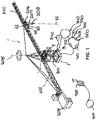
- said travel path determination module 300 can have different working modes and have corresponding modules, in particular a PTP or point-to-point control module 301, a multipoint control module 302 and a path control module 303, cf. 1 .
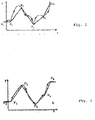
- Such a PTP control module 301 can contain a blending function, by means of which the travel path is determined in such a way that a defined target point is not approached exactly for the time-optimal method, but is instead turned off to the next point when its blending area is reached, cf. 2 .
- the named blending function of the PTP control module 301 can be designed to work asynchronously, so that blending begins when the last drive axle or drive device to be actuated reaches the sphere around the named point.
- the blending function can also be designed or controlled synchronously, so that the blending begins as soon as the leading movement or drive axis penetrates the sphere around the programmed point.
- the travel path determination module 300 can also have a multipoint control module 302, cf. 3 , which preferably determines a plurality of intermediate points 501, 502, 503, 504 . . . n between two destinations 500, 510 to be approached such that the named intermediate points 501, 502, 503, 504 . . . n form a dense sequence of time-equidistant points, cf. 4 . Approaching such time-equidistant intermediate points 501, 502, 503, 504 .
- the travel path can also be determined by a path control module 303, which calculates a continuous, mathematically defined path of motion between the target points, cf. figure 5 .
- a path control module can include an interpolator that determines intermediate values on the calculated space curve according to a specified path function or partial function, for example in the form of a straight line, a circle or a polynomial, and sends them to the drive devices or their drive controllers.
- Such an interpolator can perform a linear interpolation and/or a circular interpolation and/or a spline interpolation and/or special interpolations, for example Bezier or spiral interpolations, and this can be performed with or without smoothing.
- FIG. 5a shows a path without smoothing
- FIG. 5b a path with smoothing.
- the programming or determination of the path or the travel path can be done online or offline.
- the desired travel path can be determined in particular by a teach-in device 320, by means of which desired target and intermediate points of the desired travel path can be approached by manually operating the operating elements of the control device or by operating a handheld programming device, with the teach-in device 320 stores the specified destination and intermediate points.
- a teach-in device 320 stores the specified destination and intermediate points.
- an experienced crane operator with the control console, the crane 2 or its load hook 208 along a desired traversing path between the end points. All coordinates or intermediate points reached in this way can be stored in the controller 3 .
- the control device 3 of the crane 2 can then move to all stored destinations and intermediate points autonomously.
- the travel path determination module 300 also has a playback device 330 for determining the desired travel path by manually moving the load hook along the desired travel path.
- the automatic displacement control module 310 can advantageously take into account specifications of a sway damping device 340, wherein the mentioned sway damping device 340 can advantageously use the signals of the aforementioned detection device 60, which detects the deflection of the load hook 208 relative to the vertical 61.
- control device 3 can be connected to an external, separate master computer 400 which can have access to a building data model in the sense of a BIM model and can provide digital data from this building data model to the control device 3 .
- this digital data from the building data model can be used in particular to provide target and intermediate points for determining the desired travel path, which can dynamically take into account building data in various phases and working area limitations.
- Said control device 3 of the crane 1 can be designed in particular to said drive devices of the hoist, the Trolley and the slewing gear to control even when said pendulum damping device 340 pendulum relevant movement parameters detected.
- the crane 1 can use the aforementioned detection device 60, which detects a diagonal pull of the hoist rope 207 and/or deflections of the load hook 208 relative to the vertical 61, which passes through the suspension point of the load hook 208, ie the trolley 206.
- the cable pull angle can be detected against the line of action of gravity, ie the vertical 61, cf. 1 .
- control device 3 can control the slewing gear drive and the trolley drive with the aid of the sway damping device 340 in order to bring the trolley 206 back more or less exactly over the load hook 208 and compensate for or reduce pendulum movements or prevent them from occurring in the first place.
- sway-damping device 340 can also have determination means 342 for determining dynamic deformations of structural components, control module 341 of sway-damping device 340, which influences the activation of the drive device in a sway-dampening manner, being designed to use the determined dynamic deformations of the structural components of the drive device when influencing the activation of the drive devices Crane to consider.
- the determination means 342 can include an estimation device 343, which calculates the deformations and movements of the machine structure under dynamic loads, which change as a function of control commands entered at the control station and/or as a function of specific control actions of the drive devices and/or as a function of specific speed and/or or acceleration profiles of the drive devices result, taking into account the circumstances characterizing the crane structure.
- a calculation unit 348 can Calculate structural deformations and the resulting structural part movements using a stored calculation model depending on the control commands entered at the control station.
- the pendulum damping device 340 can also include a suitable sensor system 344, by means of which such elastic deformations and movements of structural components under dynamic loads are detected.
- a sensor system 344 can include, for example, deformation sensors such as strain gauges on the steel construction of the crane, for example the lattice framework of the tower 201 or the jib 202 .
- acceleration and/or speed sensors can be provided in order to detect specific movements of structural components such as pitching movements of the boom tip or rotary dynamic effects on boom 202 .
- inclination sensors or gyroscopes can also be provided, for example on the tower 201, in particular on its upper section, on which the boom is mounted, in order to record the dynamics of the tower 201.
- movement and/or acceleration sensors can also be assigned to the drive trains in order to be able to record the dynamics of the drive trains.
- encoders can be assigned to the deflection pulleys of the trolley 206 for the hoist rope and/or deflection pulleys for a guy rope of a luffing jib, in order to be able to detect the actual rope speed at the relevant point.
- the sway damping device 340 can include a filter device or an observer 345, which observes the crane reactions that occur with certain manipulated variables of the drive controllers 347 and taking into account predetermined laws of a dynamic model of the crane, which can fundamentally have different properties and can be generated by analyzing and simulating the Steel construction can be obtained, based on the observed crane reactions, influences the manipulated variables of the controller.
- Such a filter or observer device 345 can be embodied in particular in the form of a so-called Kalman filter 346, to which the manipulated variables of the drive controller 347 of the crane and the crane movements, in particular the cable pull angle ⁇ relative to the vertical 62 and/or its change over time or the Angular velocity of said oblique pull, is supplied and which, from these input variables using Kalman equations that model the dynamic system of the crane structure, in particular its steel components and drive trains, influences the manipulated variables of the drive controller 347 accordingly in order to achieve the desired sway-damping effect.
- Kalman filter 346 to which the manipulated variables of the drive controller 347 of the crane and the crane movements, in particular the cable pull angle ⁇ relative to the vertical 62 and/or its change over time or the Angular velocity of said oblique pull, is supplied and which, from these input variables using Kalman equations that model the dynamic system of the crane structure, in particular its steel components and drive trains, influences the manipulated variables of the drive controller 347 accordingly in
- deformations and vibration forms of the tower crane under load can be dampened or avoided from the start, as described in 7 are shown by way of example, with partial view a.) first showing schematically a pitching deformation of the tower crane under load as a result of bending of the tower 201 with the associated lowering of the boom 202 and an associated diagonal pull of the hoist cable.
- the pendulum damping device 340 can include an oblique pull control.
- the position of the load hook 208, in particular its oblique pull relative to the vertical, that is, the Deflection of the hoisting rope 207 in relation to the vertical is detected and supplied to the Kalman filter 346 mentioned.
- the position sensors can be designed to detect the load or the load hook 208 relative to a fixed world coordinate system and/or the anti-sway device 340 can be designed to position the load relative to a fixed world coordinate system.
- the sway damping device 340 can be designed to correct the slewing gear and the trolley so that the cable is always perpendicular to the load, even if the crane is swayed by the increasing load moment tends more and more forward.
- the pitching movement of the crane as a result of its deformation under the load can be taken into account and the trolley can be tracked taking into account the recorded load position or positioned with anticipatory estimation of the pitching deformation in such a way that the hoist rope is in the vertical position during the resulting crane deformation Lot is above the load.
- the greatest static deflection occurs at the point where the load leaves the ground. In this case, diagonal pull control is no longer necessary.
- the slewing gear can also be tracked, taking into account the detected load position, and/or positioned with anticipatory estimation of a transverse deformation in such a way that the hoist cable is perpendicular to the load during the resulting crane deformation.
- Such an oblique pull control can be reactivated at a later point in time by the operator, who can then use the crane as a manipulator. This means that the load can only be lifted by pushing and/or pulling reposition.
- the oblique tension control attempts to follow the deflection caused by the operator. This allows a manipulator control to be implemented.
Landscapes
- Engineering & Computer Science (AREA)
- Mechanical Engineering (AREA)
- Automation & Control Theory (AREA)
- Control And Safety Of Cranes (AREA)
- Iron Core Of Rotating Electric Machines (AREA)
Claims (15)
- Système comprenant une grue, en particulier une grue à tour, et un ordinateur maître externe, dans lequel la grue est équipée d'un moyen de levage de charge (208) monté sur un câble de levage (207), de dispositifs d'entraînement pour déplacer plusieurs éléments de grue et traverser le moyen de levage de charge (208), et d'un dispositif de commande (3) pour commander les dispositifs d'entraînement de telle sorte que le moyen de levage de charge (208) se déplace le long d'une trajectoire de déplacement entre au moins deux points cibles (500, 510), dans lequel le dispositif de commande (3) comprend- un module de détermination de trajectoire de déplacement (300) pour déterminer un trajectoire de déplacement souhaité entre les au moins deux points cibles (500, 510), qui est connecté à un dispositif de lecture (330) pour déterminer le trajectoire de déplacement souhaité et/ou les points cibles et intermédiaires (500 ... 510) souhaités du trajectoire de déplacement en déplaçant manuellement le moyen de levage de charge le long du trajectoire de déplacement souhaité, et- un module de commande de déplacement automatique (310) pour faire traverser automatiquement le moyen de levage de charge (208) le long du trajectoire de déplacement déterminé,caractérisé en ce que le module de détermination de trajectoire de déplacement (300) est couplé à l'ordinateur maître externe (400) qui a accès à un module de données de bâtiment (BIM) et fournit des points cibles et intermédiaires (500 ... 510) pour déterminer le trajectoire de déplacement, l'ordinateur maître (400) fournissant de manière cyclique ou continue des données actualisées concernant les contours de bâtiment de différentes phases de construction, et le module de détermination de trajectoire de déplacement étant configuré pour prendre en compte les données actualisées concernant les contours de bâtiment lors de la détermination du trajectoire de déplacement.
- Système selon la revendication précédente, dans lequel le module de détermination de trajectoire de déplacement (300) comprend un module de commande point à point (301) pour déterminer le trajectoire de déplacement entre les points cibles (500, 510), dans lequel le module de commande point à point (301) comprend une fonction de surlooping et est configuré pour fonctionner de manière asynchrone de telle sorte que lorsqu'il atteint une zone de surlooping d'un point cible sans s'approcher exactement de ce point cible, un virage est effectué vers le point cible suivant, dans lequel le surlooping est démarré lorsque le dernier axe de mouvement atteint une sphère autour du point cible, ou est configuré pour fonctionner de manière synchrone de telle sorte qu'en atteignant une zone de surlooping d'un point cible sans s'approcher exactement de ce point cible, un virage est effectué vers le point cible suivant, dans lequel le surlooping est démarré lorsque l'axe de mouvement principal atteint une sphère autour du point cible.
- Système selon l'une quelconque des revendications précédentes, dans lequel le module de détermination de trajectoire de déplacement (300) comprend un module de commande multipoint (302) pour déterminer une pluralité de points intermédiaires (501, 502, 503...) entre deux points cibles (500, 510), dans lequel le module de commande multipoint (302) est configuré pour fixer la pluralité de points intermédiaires à équidistance les uns des autres.
- Système selon l'une quelconque des revendications précédentes, dans lequel le module de détermination de trajectoire de déplacement (300) comprend un module de contrôle de trajectoire (303) pour déterminer un trajectoire continu, mathématiquement défini, entre deux points cibles (500, 510).
- Système selon l'une quelconque des revendications précédentes, dans lequel le module de détermination du trajectoire de déplacement (300) est connecté à un dispositif d'apprentissage (320) pour déterminer le trajectoire de déplacement souhaité en approchant manuellement les points cibles et intermédiaires (500 ... 510) souhaités.
- Système selon l'une quelconque des revendications précédentes, dans lequel le module de détermination de trajectoire de déplacement (300) est configuré pour prendre en compte des limites de plage de travail et déterminer la trajectoire de déplacement autour des limites de plage de travail.
- Système selon l'une quelconque des revendications précédentes, dans lequel un dispositif d'amortissement de balancement (340) est prévu, dans lequel le module de commande de déplacement automatique (310) prend en compte des spécifications et/ou un signal du dispositif d'amortissement de balancement (340) dans l'actionnement des dispositifs d'entraînement et la détermination des vitesses de déplacement et/ou des accélérations des dispositifs d'entraînement.
- Système selon la revendication précédente, dans lequel le dispositif d'amortissement de balancement (340) comprend un dispositif de détection (60) pour détecter la déviation du câble de levage (207) et/ou du moyen de levage de charge (208) par rapport à une verticale (61) à travers un point de suspension du câble de levage (207), dans lequel le module de commande de déplacement automatique (310) actionne les dispositifs d'entraînement en fonction d'un signal de déviation et/ou de traction diagonale dudit dispositif de détection (61).
- Système selon l'une quelconque des deux revendications précédentes, dans lequel le dispositif d'amortissement de balancement (340) comprend des moyens de détermination (342) pour déterminer des déformations et/ou des mouvements de composants structurels de la grue à la suite de charges dynamiques, dans lequel le module de commande (341) du dispositif d'amortissement de balancement (340) est configuré pour prendre en compte les déformations et/ou les mouvements déterminés des composants structurels à la suite de charges dynamiques lorsqu'il influence l'actionnement des dispositifs d'entraînement.
- Système selon la revendication précédente, dans lequel les composants structurels comprennent une tour (201) et/ou une flèche (202) et les moyens de détermination (342) sont configurés pour déterminer les déformations et/ou les charges de la tour (201) et/ou de la flèche (202) à la suite de charges dynamiques.
- Système selon l'une quelconque des deux revendications précédentes, dans lequel les composants structurels comprennent des parties de train d'entraînement telles que des parties du mécanisme de rotation, des parties d'entraînement du chariot et analogues, et les moyens de détermination (342) sont configurés pour déterminer des déformations et/ou des mouvements des parties de train d'entraînement à la suite de charges dynamiques.
- Système selon l'une quelconque des revendications 9 à 11, dans lequel les moyens de détermination (342) comprennent un dispositif d'estimation (343) pour estimer les déformations et/ou les mouvements des composants structurels à la suite de charges dynamiques sur la base de données numériques d'un modèle de données décrivant la structure de la grue, et/ou une unité de calcul (348) qui calcule les déformations structurelles et les mouvements résultants des composants structurels à l'aide d'un modèle de calcul mémorisé en fonction d'instructions de commande entrées sur le poste de commande, et/ou un système de capteurs (344) pour détecter les déformations et/ou les paramètres dynamiques des composants structurels.
- Système selon la revendication précédente, dans lequel le système de capteurs (344) comprend un capteur d'inclinaison et/ou d'accélération pour détecter les inclinaisons et/ou les vitesses de la tour, un capteur de vitesse de rotation et/ou d'accélération pour détecter la vitesse de rotation et/ou l'accélération d'une flèche et/ou un capteur de mouvement de tangage pour détecter les mouvements de tangage et/ou les accélérations de la flèche, et/ou un capteur de vitesse et/ou d'accélération du câble pour détecter les vitesses et/ou les accélérations du câble de levage (207).
- Système selon l'une quelconque des revendications 9 à 13, dans lequel le dispositif d'amortissement de balancement (340) comprend un dispositif de filtrage et/ou d'observation (345) pour influencer les variables d'actionnement des régulateurs d'entraînement (347) pour l'actionnement des dispositifs d'entraînement, dans lequel ledit dispositif de filtrage et/ou d'observation (345) est configuré pour recevoir les variables d'actionnement des régulateurs d'entraînement (347) et les mouvements détectés et/ou estimés des éléments de grue et/ou les déformations et/ou les mouvements des composants structurels, qui se produisent à la suite de charges dynamiques, en tant que variables d'entrée, et influencer les variables d'actionnement des régulateurs en fonction des mouvements des éléments de grue induits par la dynamique, obtenus pour certaines variables d'actionnement des régulateurs et/ou déformations des composants structurels, le dispositif de filtrage et/ou d'observation (345) étant configuré comme un filtre de Kalman (346), des fonctions détectées et/ou estimées et/ou calculées et/ou simulées, qui caractérisent la dynamique des composants structurels de la grue, étant implémentées dans le filtre de Kalman (346).
- Système selon l'une quelconque des revendications précédentes, dans lequel le dispositif de commande (3) comprend un système de capteurs de position qui est configuré pour détecter le moyen de levage de charge (208) par rapport à un système de coordonnées mondiales fixe et/ou est configuré pour positionner le moyen de levage de charge (208) par rapport à un système de coordonnées mondiales fixe.
Applications Claiming Priority (3)
| Application Number | Priority Date | Filing Date | Title |
|---|---|---|---|
| DE102016004249.4A DE102016004249A1 (de) | 2016-04-08 | 2016-04-08 | Kran |
| DE102016004350.4A DE102016004350A1 (de) | 2016-04-11 | 2016-04-11 | Kran und Verfahren zum Steuern eines solchen Krans |
| PCT/EP2017/000436 WO2017174196A1 (fr) | 2016-04-08 | 2017-04-06 | Grue |
Publications (2)
| Publication Number | Publication Date |
|---|---|
| EP3408211A1 EP3408211A1 (fr) | 2018-12-05 |
| EP3408211B1 true EP3408211B1 (fr) | 2022-06-08 |
Family
ID=58548653
Family Applications (1)
| Application Number | Title | Priority Date | Filing Date |
|---|---|---|---|
| EP17717626.0A Active EP3408211B1 (fr) | 2016-04-08 | 2017-04-06 | Grue |
Country Status (7)
| Country | Link |
|---|---|
| US (2) | US11084691B2 (fr) |
| EP (1) | EP3408211B1 (fr) |
| CN (1) | CN109153548B (fr) |
| BR (1) | BR112018070462A2 (fr) |
| ES (1) | ES2924051T3 (fr) |
| RU (1) | RU2734966C2 (fr) |
| WO (1) | WO2017174196A1 (fr) |
Families Citing this family (17)
| Publication number | Priority date | Publication date | Assignee | Title |
|---|---|---|---|---|
| DE102016004350A1 (de) * | 2016-04-11 | 2017-10-12 | Liebherr-Components Biberach Gmbh | Kran und Verfahren zum Steuern eines solchen Krans |
| US11124392B2 (en) | 2016-11-22 | 2021-09-21 | Manitowoc Crane Companies, Llc | Optical detection and analysis for boom angles on a crane |
| DE102017114789A1 (de) * | 2017-07-03 | 2019-01-03 | Liebherr-Components Biberach Gmbh | Kran und Verfahren zum Steuern eines solchen Krans |
| EP3461783B1 (fr) * | 2017-09-29 | 2019-11-13 | B&R Industrial Automation GmbH | Équipement de levage et procédé de commande d'un équipement de levage |
| WO2019229751A1 (fr) * | 2018-05-30 | 2019-12-05 | Syracuse Ltd. | Système et procédé de transport d'une charge hissée balançante |
| US12358763B2 (en) | 2018-11-07 | 2025-07-15 | Manitowoc Crane Companies, Llc | System for determining crane status using optical and/or electromagnetic sensors |
| US12054363B2 (en) * | 2019-02-05 | 2024-08-06 | J. Ray McDermott | System and methods for determining relative position and relative motion of objects |
| JP7151532B2 (ja) * | 2019-02-14 | 2022-10-12 | 株式会社タダノ | クレーンおよびクレーンの経路生成システム |
| US11057609B2 (en) * | 2019-02-27 | 2021-07-06 | Canon Kabushiki Kaisha | Information processing apparatus, information processing method, and computer readable storage medium for determining a moving path of virtual viewpoint |
| CN113353072A (zh) * | 2020-03-04 | 2021-09-07 | 青岛海尔工业智能研究院有限公司 | 一种行车控制方法、装置、服务器及介质 |
| CN112484973B (zh) * | 2020-11-02 | 2022-08-02 | 中冶建筑研究总院有限公司 | 一种测量钢吊车梁及吊车肢柱头的偏心荷载的方法 |
| CN112507537A (zh) * | 2020-11-26 | 2021-03-16 | 筑友智造科技投资有限公司 | 一种塔吊布置方法、装置及系统 |
| ES2989761T3 (es) | 2020-12-15 | 2024-11-27 | Schneider Electric Ind Sas | Procedimiento para optimizar una función antibalanceo |
| FR3123908B1 (fr) * | 2021-06-14 | 2023-10-27 | Manitowoc Crane Group France | Procédé de sécurisation d’une grue à la survenue d’un évènement exceptionnel |
| CN113387284A (zh) * | 2021-06-23 | 2021-09-14 | 湖南三一塔式起重机械有限公司 | 一种塔机回转速度的控制方法、系统及塔式起重机 |
| CN115330035A (zh) * | 2022-07-29 | 2022-11-11 | 浙江三一装备有限公司 | 吊装路径规划模型构建方法、吊装路径规划方法及起重机 |
| CN117446664B (zh) * | 2023-10-26 | 2024-05-07 | 渤海大学 | 一种基于快速有限时间指令滤波器的塔式起重机控制方法 |
Family Cites Families (21)
| Publication number | Priority date | Publication date | Assignee | Title |
|---|---|---|---|---|
| US4172685A (en) * | 1976-10-22 | 1979-10-30 | Hitachi, Ltd. | Method and apparatus for automatic operation of container crane |
| JPS6317793A (ja) * | 1986-07-11 | 1988-01-25 | 株式会社日立製作所 | クレ−ンの制御方式 |
| US5806696A (en) * | 1993-02-01 | 1998-09-15 | Hytonen; Kimmo | Method and equipment for controlling the operations of a crane |
| DE10064182A1 (de) * | 2000-10-19 | 2002-05-08 | Liebherr Werk Nenzing | Kran oder Bagger zum Umschlagen von einer an einem Lastseil hängenden Last mit Lastpendelungsdämpfung |
| DE102004045749A1 (de) | 2004-09-21 | 2006-04-06 | Liebherr-Werk Nenzing Gmbh, Nenzing | Verfahren zum automatischen Umschlagen von einer an einem Lastseil hängenden Last eines Kranes oder Baggers mit Lastpendelungsdämpfung und Bahnplaner |
| DE102005002192B4 (de) * | 2005-01-17 | 2008-08-14 | Siemens Ag | Verfahren zum Betrieb einer Krananlage, insbesondere eines Containerkrans, sowie Krananlage, insbesondere Containerkran |
| DE102007041692A1 (de) | 2007-09-03 | 2009-03-05 | Siemens Ag | Regelungseinrichtung zur Dämpfung von Pendelbewegungen einer seilgeführten Last |
| DE102009016366A1 (de) | 2008-04-11 | 2009-12-17 | Terex-Demag Gmbh | Kran sowie Verfahren und System zum Betreiben eines Krans mit Hilfe von GPS |
| RU2403204C1 (ru) * | 2009-07-15 | 2010-11-10 | Общество с ограниченной ответственностью "Научно-производственное предприятие "Резонанс" | Устройство для контроля линейного или углового перемещения оборудования или механизма грузоподъемной машины (варианты) |
| CN101704472B (zh) * | 2009-11-19 | 2011-08-17 | 绍兴文理学院 | 塔吊全自动控制系统 |
| US8909467B2 (en) | 2010-06-07 | 2014-12-09 | Industry-Academic Cooperation Foundation, Yonsei University | Tower crane navigation system |
| DE102011001112A1 (de) | 2011-03-04 | 2012-09-06 | Schneider Electric Automation Gmbh | Verfahren und Steuerungseinrichtung zur schwingungsarmen Bewegung eines bewegbaren Kranelementes eines Kransystems |
| JP5293977B2 (ja) * | 2011-03-17 | 2013-09-18 | 富士電機株式会社 | クレーンの振れ止め制御方法及び振れ止め制御装置 |
| EP2562125B1 (fr) | 2011-08-26 | 2014-01-22 | Liebherr-Werk Nenzing GmbH | Appareil de commande de grue |
| DE102012004739A1 (de) | 2012-03-08 | 2013-09-12 | Liebherr-Werk Nenzing Gmbh | Kran und Verfahren zur Kransteuerung |
| DE102013006258A1 (de) | 2013-04-11 | 2014-10-16 | Liebherr-Components Biberach Gmbh | Kran |
| DE102013012019B4 (de) | 2013-07-19 | 2019-10-24 | Tadano Faun Gmbh | Kran, insbesondere Mobilkran |
| JP6053168B2 (ja) | 2013-09-27 | 2016-12-27 | 株式会社日立製作所 | 搬送経路計算システム |
| US20160034730A1 (en) * | 2014-07-31 | 2016-02-04 | Trimble Navigation Limited | Asset location on construction site |
| US20160035251A1 (en) * | 2014-07-31 | 2016-02-04 | Trimble Navigation Limited | Crane operator guidance |
| FR3037681B1 (fr) * | 2015-06-18 | 2017-11-24 | Manitowoc Crane Group France | Procede de definition d’une courbe de charges optimisee pour grue, procede et dispositif de controle pour controler la charge suspendue a une grue a partir de la courbe de charges optimisee |
-
2017
- 2017-04-06 WO PCT/EP2017/000436 patent/WO2017174196A1/fr not_active Ceased
- 2017-04-06 US US16/091,995 patent/US11084691B2/en active Active
- 2017-04-06 BR BR112018070462A patent/BR112018070462A2/pt not_active IP Right Cessation
- 2017-04-06 CN CN201780024871.9A patent/CN109153548B/zh active Active
- 2017-04-06 EP EP17717626.0A patent/EP3408211B1/fr active Active
- 2017-04-06 RU RU2018139050A patent/RU2734966C2/ru active
- 2017-04-06 ES ES17717626T patent/ES2924051T3/es active Active
-
2021
- 2021-07-12 US US17/373,052 patent/US11807501B2/en active Active
Non-Patent Citations (2)
| Title |
|---|
| DATABASE COMPENDEX [online] ENGINEERING INFORMATION, INC., NEW YORK, NY, US; 2011, SCHAPER U ET AL: "A load position observer for cranes with gyroscope measurements", Database accession no. E20124015493306 * |
| SCHAPER U ET AL: "A load position observer for cranes with gyroscope measurements", IFAC PROCEEDINGS VOLUMES (IFAC-PAPERSONLINE) - PROCEEDINGS OF THE 18TH IFAC WORLD CONGRESS 2011 IFAC SECRETARIAT AUS, vol. 18, no. PART 1, 2011, pages 3563 - 3568, DOI: 10.3182/20110828-6-IT-1002.01456 * |
Also Published As
| Publication number | Publication date |
|---|---|
| US11807501B2 (en) | 2023-11-07 |
| US20210339988A1 (en) | 2021-11-04 |
| US11084691B2 (en) | 2021-08-10 |
| US20190112165A1 (en) | 2019-04-18 |
| CN109153548A (zh) | 2019-01-04 |
| EP3408211A1 (fr) | 2018-12-05 |
| BR112018070462A2 (pt) | 2019-02-05 |
| RU2734966C2 (ru) | 2020-10-26 |
| CN109153548B (zh) | 2021-09-07 |
| WO2017174196A1 (fr) | 2017-10-12 |
| RU2018139050A3 (fr) | 2020-06-18 |
| RU2018139050A (ru) | 2020-05-12 |
| ES2924051T3 (es) | 2022-10-04 |
Similar Documents
| Publication | Publication Date | Title |
|---|---|---|
| EP3408211B1 (fr) | Grue | |
| EP3784616B1 (fr) | Grue et procédé pour commander une grue de ce type | |
| EP3408208B1 (fr) | Grue et procédé de commande de ladite grue | |
| EP3649072B1 (fr) | Grue et procédé de commande d'une telle grue | |
| EP4013713B1 (fr) | Grue et procédé de commande d'une telle grue | |
| EP3426851B1 (fr) | Engin de chantier, en particulier grue, et procédé de commande dudit engin de chantier | |
| DE102016004249A1 (de) | Kran | |
| EP2272784B1 (fr) | Grue pour envelopper une charge suspendue à un câble porteur | |
| WO2017174195A1 (fr) | Procédé et dispositif pour planifier et/ou commander et/ou simuler le fonctionnement d'un engin de chantier | |
| WO2021099374A1 (fr) | Machine de construction et/ou de manipulation de matériaux | |
| DE102015100669A1 (de) | Anti-pendel-steuerverfahren mit einstellbarer unterstützung für den transport einer schwebenden last | |
| AT520763B1 (de) | Kransteuerung | |
| EP4707217A2 (fr) | Grue à tour, procédé et unité de commande pour faire fonctionner une grue à tour, chariot et train d'atterrissage | |
| EP0907604A1 (fr) | Procede et systeme pour eviter les oscillations en charge d'un appareil depla ant une charge suspendue et executant des mouvements rotatifs | |
| EP3810378A1 (fr) | Procédé de commande de mécanismes d'entraînement d'un robot et système de robot | |
| WO2024083442A1 (fr) | Procédé et système pour faire fonctionner un système de matériau de construction | |
| WO2022073680A1 (fr) | Appareil de levage, tel qu'une grue, et procédé et appareil de commande d'un tel appareil de levage |
Legal Events
| Date | Code | Title | Description |
|---|---|---|---|
| STAA | Information on the status of an ep patent application or granted ep patent |
Free format text: STATUS: UNKNOWN |
|
| STAA | Information on the status of an ep patent application or granted ep patent |
Free format text: STATUS: THE INTERNATIONAL PUBLICATION HAS BEEN MADE |
|
| PUAI | Public reference made under article 153(3) epc to a published international application that has entered the european phase |
Free format text: ORIGINAL CODE: 0009012 |
|
| STAA | Information on the status of an ep patent application or granted ep patent |
Free format text: STATUS: REQUEST FOR EXAMINATION WAS MADE |
|
| 17P | Request for examination filed |
Effective date: 20180831 |
|
| AK | Designated contracting states |
Kind code of ref document: A1 Designated state(s): AL AT BE BG CH CY CZ DE DK EE ES FI FR GB GR HR HU IE IS IT LI LT LU LV MC MK MT NL NO PL PT RO RS SE SI SK SM TR |
|
| AX | Request for extension of the european patent |
Extension state: BA ME |
|
| DAV | Request for validation of the european patent (deleted) | ||
| DAX | Request for extension of the european patent (deleted) | ||
| GRAP | Despatch of communication of intention to grant a patent |
Free format text: ORIGINAL CODE: EPIDOSNIGR1 |
|
| STAA | Information on the status of an ep patent application or granted ep patent |
Free format text: STATUS: GRANT OF PATENT IS INTENDED |
|
| INTG | Intention to grant announced |
Effective date: 20211129 |
|
| GRAS | Grant fee paid |
Free format text: ORIGINAL CODE: EPIDOSNIGR3 |
|
| GRAA | (expected) grant |
Free format text: ORIGINAL CODE: 0009210 |
|
| STAA | Information on the status of an ep patent application or granted ep patent |
Free format text: STATUS: THE PATENT HAS BEEN GRANTED |
|
| AK | Designated contracting states |
Kind code of ref document: B1 Designated state(s): AL AT BE BG CH CY CZ DE DK EE ES FI FR GB GR HR HU IE IS IT LI LT LU LV MC MK MT NL NO PL PT RO RS SE SI SK SM TR |
|
| REG | Reference to a national code |
Ref country code: AT Ref legal event code: REF Ref document number: 1496810 Country of ref document: AT Kind code of ref document: T Effective date: 20220615 Ref country code: CH Ref legal event code: EP |
|
| REG | Reference to a national code |
Ref country code: DE Ref legal event code: R096 Ref document number: 502017013286 Country of ref document: DE |
|
| REG | Reference to a national code |
Ref country code: IE Ref legal event code: FG4D Free format text: LANGUAGE OF EP DOCUMENT: GERMAN |
|
| RAP2 | Party data changed (patent owner data changed or rights of a patent transferred) |
Owner name: LIEBHERR-WERK BIBERACH GMBH |
|
| REG | Reference to a national code |
Ref country code: DE Ref legal event code: R081 Ref document number: 502017013286 Country of ref document: DE Owner name: LIEBHERR-WERK BIBERACH GMBH, DE Free format text: FORMER OWNER: LIEBHERR-COMPONENTS BIBERACH GMBH, 88400 BIBERACH, DE |
|
| REG | Reference to a national code |
Ref country code: NL Ref legal event code: FP Ref country code: GB Ref legal event code: 732E Free format text: REGISTERED BETWEEN 20220721 AND 20220727 |
|
| REG | Reference to a national code |
Ref country code: LT Ref legal event code: MG9D |
|
| REG | Reference to a national code |
Ref country code: ES Ref legal event code: FG2A Ref document number: 2924051 Country of ref document: ES Kind code of ref document: T3 Effective date: 20221004 |
|
| PG25 | Lapsed in a contracting state [announced via postgrant information from national office to epo] |
Ref country code: SE Free format text: LAPSE BECAUSE OF FAILURE TO SUBMIT A TRANSLATION OF THE DESCRIPTION OR TO PAY THE FEE WITHIN THE PRESCRIBED TIME-LIMIT Effective date: 20220608 Ref country code: NO Free format text: LAPSE BECAUSE OF FAILURE TO SUBMIT A TRANSLATION OF THE DESCRIPTION OR TO PAY THE FEE WITHIN THE PRESCRIBED TIME-LIMIT Effective date: 20220908 Ref country code: LT Free format text: LAPSE BECAUSE OF FAILURE TO SUBMIT A TRANSLATION OF THE DESCRIPTION OR TO PAY THE FEE WITHIN THE PRESCRIBED TIME-LIMIT Effective date: 20220608 Ref country code: HR Free format text: LAPSE BECAUSE OF FAILURE TO SUBMIT A TRANSLATION OF THE DESCRIPTION OR TO PAY THE FEE WITHIN THE PRESCRIBED TIME-LIMIT Effective date: 20220608 Ref country code: GR Free format text: LAPSE BECAUSE OF FAILURE TO SUBMIT A TRANSLATION OF THE DESCRIPTION OR TO PAY THE FEE WITHIN THE PRESCRIBED TIME-LIMIT Effective date: 20220909 Ref country code: FI Free format text: LAPSE BECAUSE OF FAILURE TO SUBMIT A TRANSLATION OF THE DESCRIPTION OR TO PAY THE FEE WITHIN THE PRESCRIBED TIME-LIMIT Effective date: 20220608 Ref country code: BG Free format text: LAPSE BECAUSE OF FAILURE TO SUBMIT A TRANSLATION OF THE DESCRIPTION OR TO PAY THE FEE WITHIN THE PRESCRIBED TIME-LIMIT Effective date: 20220908 |
|
| PG25 | Lapsed in a contracting state [announced via postgrant information from national office to epo] |
Ref country code: RS Free format text: LAPSE BECAUSE OF FAILURE TO SUBMIT A TRANSLATION OF THE DESCRIPTION OR TO PAY THE FEE WITHIN THE PRESCRIBED TIME-LIMIT Effective date: 20220608 Ref country code: LV Free format text: LAPSE BECAUSE OF FAILURE TO SUBMIT A TRANSLATION OF THE DESCRIPTION OR TO PAY THE FEE WITHIN THE PRESCRIBED TIME-LIMIT Effective date: 20220608 |
|
| PG25 | Lapsed in a contracting state [announced via postgrant information from national office to epo] |
Ref country code: SM Free format text: LAPSE BECAUSE OF FAILURE TO SUBMIT A TRANSLATION OF THE DESCRIPTION OR TO PAY THE FEE WITHIN THE PRESCRIBED TIME-LIMIT Effective date: 20220608 Ref country code: SK Free format text: LAPSE BECAUSE OF FAILURE TO SUBMIT A TRANSLATION OF THE DESCRIPTION OR TO PAY THE FEE WITHIN THE PRESCRIBED TIME-LIMIT Effective date: 20220608 Ref country code: RO Free format text: LAPSE BECAUSE OF FAILURE TO SUBMIT A TRANSLATION OF THE DESCRIPTION OR TO PAY THE FEE WITHIN THE PRESCRIBED TIME-LIMIT Effective date: 20220608 Ref country code: PT Free format text: LAPSE BECAUSE OF FAILURE TO SUBMIT A TRANSLATION OF THE DESCRIPTION OR TO PAY THE FEE WITHIN THE PRESCRIBED TIME-LIMIT Effective date: 20221010 Ref country code: EE Free format text: LAPSE BECAUSE OF FAILURE TO SUBMIT A TRANSLATION OF THE DESCRIPTION OR TO PAY THE FEE WITHIN THE PRESCRIBED TIME-LIMIT Effective date: 20220608 Ref country code: CZ Free format text: LAPSE BECAUSE OF FAILURE TO SUBMIT A TRANSLATION OF THE DESCRIPTION OR TO PAY THE FEE WITHIN THE PRESCRIBED TIME-LIMIT Effective date: 20220608 |
|
| PG25 | Lapsed in a contracting state [announced via postgrant information from national office to epo] |
Ref country code: PL Free format text: LAPSE BECAUSE OF FAILURE TO SUBMIT A TRANSLATION OF THE DESCRIPTION OR TO PAY THE FEE WITHIN THE PRESCRIBED TIME-LIMIT Effective date: 20220608 Ref country code: IS Free format text: LAPSE BECAUSE OF FAILURE TO SUBMIT A TRANSLATION OF THE DESCRIPTION OR TO PAY THE FEE WITHIN THE PRESCRIBED TIME-LIMIT Effective date: 20221008 |
|
| REG | Reference to a national code |
Ref country code: DE Ref legal event code: R097 Ref document number: 502017013286 Country of ref document: DE |
|
| PG25 | Lapsed in a contracting state [announced via postgrant information from national office to epo] |
Ref country code: AL Free format text: LAPSE BECAUSE OF FAILURE TO SUBMIT A TRANSLATION OF THE DESCRIPTION OR TO PAY THE FEE WITHIN THE PRESCRIBED TIME-LIMIT Effective date: 20220608 |
|
| PLBE | No opposition filed within time limit |
Free format text: ORIGINAL CODE: 0009261 |
|
| STAA | Information on the status of an ep patent application or granted ep patent |
Free format text: STATUS: NO OPPOSITION FILED WITHIN TIME LIMIT |
|
| PG25 | Lapsed in a contracting state [announced via postgrant information from national office to epo] |
Ref country code: DK Free format text: LAPSE BECAUSE OF FAILURE TO SUBMIT A TRANSLATION OF THE DESCRIPTION OR TO PAY THE FEE WITHIN THE PRESCRIBED TIME-LIMIT Effective date: 20220608 |
|
| 26N | No opposition filed |
Effective date: 20230310 |
|
| PG25 | Lapsed in a contracting state [announced via postgrant information from national office to epo] |
Ref country code: SI Free format text: LAPSE BECAUSE OF FAILURE TO SUBMIT A TRANSLATION OF THE DESCRIPTION OR TO PAY THE FEE WITHIN THE PRESCRIBED TIME-LIMIT Effective date: 20220608 |
|
| P01 | Opt-out of the competence of the unified patent court (upc) registered |
Effective date: 20230704 |
|
| PG25 | Lapsed in a contracting state [announced via postgrant information from national office to epo] |
Ref country code: LU Free format text: LAPSE BECAUSE OF NON-PAYMENT OF DUE FEES Effective date: 20230406 |
|
| REG | Reference to a national code |
Ref country code: BE Ref legal event code: MM Effective date: 20230430 |
|
| PG25 | Lapsed in a contracting state [announced via postgrant information from national office to epo] |
Ref country code: MC Free format text: LAPSE BECAUSE OF FAILURE TO SUBMIT A TRANSLATION OF THE DESCRIPTION OR TO PAY THE FEE WITHIN THE PRESCRIBED TIME-LIMIT Effective date: 20220608 |
|
| PG25 | Lapsed in a contracting state [announced via postgrant information from national office to epo] |
Ref country code: MC Free format text: LAPSE BECAUSE OF FAILURE TO SUBMIT A TRANSLATION OF THE DESCRIPTION OR TO PAY THE FEE WITHIN THE PRESCRIBED TIME-LIMIT Effective date: 20220608 Ref country code: IT Free format text: LAPSE BECAUSE OF FAILURE TO SUBMIT A TRANSLATION OF THE DESCRIPTION OR TO PAY THE FEE WITHIN THE PRESCRIBED TIME-LIMIT Effective date: 20220608 |
|
| REG | Reference to a national code |
Ref country code: IE Ref legal event code: MM4A |
|
| PG25 | Lapsed in a contracting state [announced via postgrant information from national office to epo] |
Ref country code: BE Free format text: LAPSE BECAUSE OF NON-PAYMENT OF DUE FEES Effective date: 20230430 |
|
| PG25 | Lapsed in a contracting state [announced via postgrant information from national office to epo] |
Ref country code: IE Free format text: LAPSE BECAUSE OF NON-PAYMENT OF DUE FEES Effective date: 20230406 |
|
| PG25 | Lapsed in a contracting state [announced via postgrant information from national office to epo] |
Ref country code: IE Free format text: LAPSE BECAUSE OF NON-PAYMENT OF DUE FEES Effective date: 20230406 |
|
| PG25 | Lapsed in a contracting state [announced via postgrant information from national office to epo] |
Ref country code: BG Free format text: LAPSE BECAUSE OF FAILURE TO SUBMIT A TRANSLATION OF THE DESCRIPTION OR TO PAY THE FEE WITHIN THE PRESCRIBED TIME-LIMIT Effective date: 20220608 |
|
| PG25 | Lapsed in a contracting state [announced via postgrant information from national office to epo] |
Ref country code: BG Free format text: LAPSE BECAUSE OF FAILURE TO SUBMIT A TRANSLATION OF THE DESCRIPTION OR TO PAY THE FEE WITHIN THE PRESCRIBED TIME-LIMIT Effective date: 20220608 |
|
| PGFP | Annual fee paid to national office [announced via postgrant information from national office to epo] |
Ref country code: NL Payment date: 20250426 Year of fee payment: 9 |
|
| PGFP | Annual fee paid to national office [announced via postgrant information from national office to epo] |
Ref country code: DE Payment date: 20250430 Year of fee payment: 9 |
|
| PGFP | Annual fee paid to national office [announced via postgrant information from national office to epo] |
Ref country code: ES Payment date: 20250505 Year of fee payment: 9 |
|
| PGFP | Annual fee paid to national office [announced via postgrant information from national office to epo] |
Ref country code: FR Payment date: 20250426 Year of fee payment: 9 |
|
| PGFP | Annual fee paid to national office [announced via postgrant information from national office to epo] |
Ref country code: CH Payment date: 20250501 Year of fee payment: 9 |
|
| PGFP | Annual fee paid to national office [announced via postgrant information from national office to epo] |
Ref country code: AT Payment date: 20250424 Year of fee payment: 9 |
|
| PG25 | Lapsed in a contracting state [announced via postgrant information from national office to epo] |
Ref country code: CY Free format text: LAPSE BECAUSE OF FAILURE TO SUBMIT A TRANSLATION OF THE DESCRIPTION OR TO PAY THE FEE WITHIN THE PRESCRIBED TIME-LIMIT; INVALID AB INITIO Effective date: 20170406 |
|
| PG25 | Lapsed in a contracting state [announced via postgrant information from national office to epo] |
Ref country code: HU Free format text: LAPSE BECAUSE OF FAILURE TO SUBMIT A TRANSLATION OF THE DESCRIPTION OR TO PAY THE FEE WITHIN THE PRESCRIBED TIME-LIMIT; INVALID AB INITIO Effective date: 20170406 |
|
| PG25 | Lapsed in a contracting state [announced via postgrant information from national office to epo] |
Ref country code: TR Free format text: LAPSE BECAUSE OF FAILURE TO SUBMIT A TRANSLATION OF THE DESCRIPTION OR TO PAY THE FEE WITHIN THE PRESCRIBED TIME-LIMIT Effective date: 20220608 |
|
| PGFP | Annual fee paid to national office [announced via postgrant information from national office to epo] |
Ref country code: GB Payment date: 20260226 Year of fee payment: 10 |