EP3408558B1 - Support hydraulique avec vanne de depression - Google Patents
Support hydraulique avec vanne de depression Download PDFInfo
- Publication number
- EP3408558B1 EP3408558B1 EP17701841.3A EP17701841A EP3408558B1 EP 3408558 B1 EP3408558 B1 EP 3408558B1 EP 17701841 A EP17701841 A EP 17701841A EP 3408558 B1 EP3408558 B1 EP 3408558B1
- Authority
- EP
- European Patent Office
- Prior art keywords
- diaphragm
- lower nozzle
- hydromount
- valve opening
- working chamber
- Prior art date
- Legal status (The legal status is an assumption and is not a legal conclusion. Google has not performed a legal analysis and makes no representation as to the accuracy of the status listed.)
- Active
Links
Images


Classifications
-
- B—PERFORMING OPERATIONS; TRANSPORTING
- B60—VEHICLES IN GENERAL
- B60K—ARRANGEMENT OR MOUNTING OF PROPULSION UNITS OR OF TRANSMISSIONS IN VEHICLES; ARRANGEMENT OR MOUNTING OF PLURAL DIVERSE PRIME-MOVERS IN VEHICLES; AUXILIARY DRIVES FOR VEHICLES; INSTRUMENTATION OR DASHBOARDS FOR VEHICLES; ARRANGEMENTS IN CONNECTION WITH COOLING, AIR INTAKE, GAS EXHAUST OR FUEL SUPPLY OF PROPULSION UNITS IN VEHICLES
- B60K5/00—Arrangement or mounting of internal-combustion or jet-propulsion units
- B60K5/12—Arrangement of engine supports
- B60K5/1208—Resilient supports
-
- F—MECHANICAL ENGINEERING; LIGHTING; HEATING; WEAPONS; BLASTING
- F16—ENGINEERING ELEMENTS AND UNITS; GENERAL MEASURES FOR PRODUCING AND MAINTAINING EFFECTIVE FUNCTIONING OF MACHINES OR INSTALLATIONS; THERMAL INSULATION IN GENERAL
- F16F—SPRINGS; SHOCK-ABSORBERS; MEANS FOR DAMPING VIBRATION
- F16F13/00—Units comprising springs of the non-fluid type as well as vibration-dampers, shock-absorbers, or fluid springs
- F16F13/04—Units comprising springs of the non-fluid type as well as vibration-dampers, shock-absorbers, or fluid springs comprising both a plastics spring and a damper, e.g. a friction damper
- F16F13/06—Units comprising springs of the non-fluid type as well as vibration-dampers, shock-absorbers, or fluid springs comprising both a plastics spring and a damper, e.g. a friction damper the damper being a fluid damper, e.g. the plastics spring not forming a part of the wall of the fluid chamber of the damper
- F16F13/08—Units comprising springs of the non-fluid type as well as vibration-dampers, shock-absorbers, or fluid springs comprising both a plastics spring and a damper, e.g. a friction damper the damper being a fluid damper, e.g. the plastics spring not forming a part of the wall of the fluid chamber of the damper the plastics spring forming at least a part of the wall of the fluid chamber of the damper
- F16F13/10—Units comprising springs of the non-fluid type as well as vibration-dampers, shock-absorbers, or fluid springs comprising both a plastics spring and a damper, e.g. a friction damper the damper being a fluid damper, e.g. the plastics spring not forming a part of the wall of the fluid chamber of the damper the plastics spring forming at least a part of the wall of the fluid chamber of the damper the wall being at least in part formed by a flexible membrane or the like
- F16F13/105—Units comprising springs of the non-fluid type as well as vibration-dampers, shock-absorbers, or fluid springs comprising both a plastics spring and a damper, e.g. a friction damper the damper being a fluid damper, e.g. the plastics spring not forming a part of the wall of the fluid chamber of the damper the plastics spring forming at least a part of the wall of the fluid chamber of the damper the wall being at least in part formed by a flexible membrane or the like characterised by features of partitions between two working chambers
- F16F13/106—Design of constituent elastomeric parts, e.g. decoupling valve elements, or of immediate abutments therefor, e.g. cages
-
- F—MECHANICAL ENGINEERING; LIGHTING; HEATING; WEAPONS; BLASTING
- F16—ENGINEERING ELEMENTS AND UNITS; GENERAL MEASURES FOR PRODUCING AND MAINTAINING EFFECTIVE FUNCTIONING OF MACHINES OR INSTALLATIONS; THERMAL INSULATION IN GENERAL
- F16F—SPRINGS; SHOCK-ABSORBERS; MEANS FOR DAMPING VIBRATION
- F16F2224/00—Materials; Material properties
- F16F2224/02—Materials; Material properties solids
- F16F2224/025—Elastomers
Definitions
- the present invention relates to a hydraulic bearing, in particular for mounting a motor vehicle engine on a vehicle body, comprising a suspension spring which supports a bearing core, encloses a working chamber and is supported on an outer ring, an intermediate plate and a diaphragm separated from the working chamber by the intermediate plate and covered by a compensating diaphragm Delimited compensation chamber, wherein the compensation chamber and the working chamber are filled with a damping liquid and are connected to one another in a fluid-conducting manner via a damping channel arranged in the intermediate plate, the intermediate plate having an upper nozzle disk, a lower nozzle disk and a membrane arranged between the upper nozzle disk and the lower nozzle disk, wherein the diaphragm has an inner perimeter, an outer perimeter, and at least one valve opening, and wherein the at least one valve opening is disposed entirely between the inner perimeter and the outer perimeter.
- Such hydraulically damping mounts are used in particular to support a motor vehicle engine on a vehicle body, on the one hand to dampen the vibrations caused by bumps in the road and on the other hand to isolate acoustic vibrations.
- the vibrations caused by unevenness in the road are dampened by a hydraulic system, the hydraulic system being formed by the liquid-damped working chamber, the compensation chamber and the damping channel connecting the two chambers with one another.
- the functioning of the hydraulic system can be described as follows: The working chamber is enlarged or reduced by a movement of the suspension spring, whereby the liquid in the working chamber is pressed into the compensation chamber via the damping channel. The liquid oscillating in the damping channel causes a Damping. If there is a negative pressure in the working chamber compared to the equalizing chamber, the liquid flows back from the equalizing chamber into the working chamber.
- the separating element comprises a membrane which has a pressure relief valve in a middle section.
- the center portion with the relief valve is made thinner than the main body of the diaphragm and has a relief hole at its center.
- a hydraulic bearing in which a working chamber and a compensating chamber are separated by a separating element.
- the separating element comprises a separating element body into which a disc-shaped cover is inserted.
- a valve element is fixed between the separator body and the cover.
- the valve element is provided with valve openings.
- EP 2 960 543 A1 discloses a hydraulic bearing with a suspension spring which supports a bearing core, encloses a working chamber and is supported on an outer ring, an intermediate plate and a compensation chamber which is separated from the working chamber by the intermediate plate and is delimited by a rolling bellows.
- the intermediate plate has an upper orifice disk, a lower orifice disk, and a membrane arranged between the upper orifice disk and the lower orifice disk.
- the membrane includes slotted valve openings.
- document JP H02 26336 A discloses the preamble of claim 1.
- Document U.S.A. 4,850,578 discloses a hydraulic mount with a membrane that is accommodated with axial play.
- the object of the present invention is to improve devices of the known type with regard to the development of undesired noises at large amplitudes.
- the membrane between the upper nozzle disk and the lower nozzle disk is accommodated with an axial play in order to be lifted and arched when there is a negative pressure in the working chamber.
- the membrane is placed in the lower nozzle disk in such a way that the at least one valve opening rests on the material of the lower nozzle disk.
- the intermediate plate with the membrane and the orifice discs represents a unidirectional valve.
- the membrane is pressed onto the lower orifice disc. Damping fluid then only flows through the damping channel from the working chamber into the compensation chamber.
- the lower nozzle disk has a receiving area for receiving the membrane, which includes a nozzle arrangement and a material section.
- the membrane can thus be accommodated in the accommodation area and is secured against radial slipping on the lower nozzle disk.
- the material section advantageously has at least one projection which is designed to engage in the valve opening of the membrane. The membrane is thus also secured against twisting in the receiving area and fixed in its position in the receiving area.
- the lower nozzle disk advantageously has at least one centering pin and the upper nozzle disk has at least one centering opening, the at least one centering pin being designed to be inserted into the at least one centering opening. In this way, the lower nozzle disk and the upper nozzle disk can be connected to one another and secured against slipping or twisting.
- the valve opening is advantageously designed as an elongated hole. Such a design also enables large volumes to be passed through and thus improves the valve behavior in the case of large amplitudes.
- the longitudinal axis of the valve opening is offset from the radial direction.
- the diaphragm is fixed between the upper orifice disk and the lower orifice disk with axial play, which allows the diaphragm to lift or deflect more easily.
- the membrane is advantageously made of an elastic material.
- the membrane advantageously has a surface structure, with the surface structure preferably being in the form of knobs.
- the hydraulic bearing 10 has a suspension spring 11 made of an elastomeric material for supporting a bearing core 12 that is vulcanized in place.
- the motor is fastened to the bearing core 12 (not shown).
- a screw 21 is embedded in the bearing core 12 in the bearing core 12 .
- the suspension spring 11 is supported on an outer ring 25 and delimits a working chamber 13 which is separated from a compensating chamber 17 by means of an intermediate plate 14 .
- the compensating chamber 17 is delimited by a compensating membrane 15, which is also referred to as a rolling bellows.
- the chambers 13 and 17 are filled with a hydraulic fluid and are connected to one another in a fluid-conducting manner via a damping channel 16 arranged in the intermediate plate 14 .
- the intermediate plate 14 has an upper nozzle disk 18 and a lower nozzle disk 19 .
- the upper nozzle disk 18 and the lower nozzle disk 19 are made of plastic.
- a membrane 20 is accommodated between the upper nozzle disk 18 and the lower nozzle disk 19 .
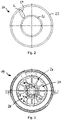
- the membrane 20 is designed in the shape of a ring and has an inner circumference 22 and an outer circumference 23 . Furthermore, the membrane 20 has a valve opening 24 which is arranged completely between the inner circumference 22 and the outer circumference 23 . As a result, the valve opening is completely limited by the material of the diaphragm 20.
- valve opening 24 is in the form of a slot.
- the longitudinal axis L of the valve opening 24 is arranged offset to the radial direction of the membrane 20, i.e. the extension of the longitudinal axis L does not go through the center of the membrane 20.
- the membrane 20 is made of an elastic material and has a knobbed surface structure (not shown).
- FIG. 3 shows a plan view of a lower nozzle disk 19.
- FIG. 14 shows a cross-sectional view of the lower nozzle disk 19 along the line of FIG 3 .
- the lower nozzle disk 19 has a receiving area 26 for receiving the membrane 20 .
- the receiving area 26 is designed as an annular depression in the lower nozzle disk 19 .
- the receiving area 26 is thus designed such that the annular membrane 20 from 2 can be included in this.
- the receiving area 26 has a nozzle arrangement 27 and a material section 28 .
- the nozzle arrangement 27 is formed by a plurality of recesses which adjoin one another along the annular receiving area 26 . When installed, the nozzle arrangement 27 forms a passage to the compensation chamber 17.
- the receiving region 26 has no recesses on the material section 28 . This is closed at the bottom by the material of the lower nozzle disk 19.
- the material section 28 has two projections 29 .
- the projections 29 are designed in such a way that they can engage in the valve opening 24 of the membrane 20 . Accordingly, the intermediate plate 14 is to be mounted in such a way that the membrane 20 is to be inserted into the receiving area 26 of the lower nozzle disk 19 in such a way that the projections 29 engage exactly in the valve opening 24 .
- the lower nozzle disc 19 has three centering pins 30 on its side facing the working chamber 13 .
- the centering pins 30 are arranged uniformly along a circular path drawn around the center point of the lower nozzle disc 19, ie each offset by 120°.
- FIG 5 shows an upper nozzle disk 18 according to the invention.
- the upper nozzle disk 18 has three centering openings 31 which are designed and arranged in such a way that the three centering pins 30 of the lower nozzle disk 19 can be inserted into them.
- the lower nozzle disk 19 thus accommodates the upper nozzle disk 18 .
- the membrane 20 is then accommodated between the lower nozzle disk 19 and the upper nozzle disk 18 .
- the upper nozzle disk 18 also has a nozzle arrangement which forms a passage to the working chamber 13 in the assembled state.
- the intermediate plate 14 consisting of the lower nozzle disc 19, the upper nozzle disc 18 and the membrane 20, is installed in the hydraulic bearing 10, it separates the working chamber 13 from the compensation chamber 17.
- the membrane 20 is then inserted into the lower nozzle disc 19 in such a way that the Valve opening 24 rests on the material of the lower nozzle disc 19.
- the intermediate plate 14 represents a unidirectional valve.
- the membrane 20 is pressed onto the lower nozzle disk 19. Damping fluid then flows through the damping channel 16 from the working chamber 13 into the compensation chamber 17.
- the negative pressure acts through the nozzle arrangement of the upper nozzle disk 18 on the membrane 20, so that the latter is lifted and arched.
- the channel for the return flow of the damping fluid is thus formed between the membrane 20 and the lower nozzle disk 19 .
- the damping fluid can then flow back from the compensating chamber 17 through the nozzle arrangement of the lower nozzle disk 19, the valve opening 24 of the membrane 20 and the nozzle arrangement of the upper nozzle disk 18 into the working chamber 13.
Landscapes
- Engineering & Computer Science (AREA)
- General Engineering & Computer Science (AREA)
- Mechanical Engineering (AREA)
- Chemical & Material Sciences (AREA)
- Combustion & Propulsion (AREA)
- Transportation (AREA)
- Combined Devices Of Dampers And Springs (AREA)
Claims (8)
- Palier hydraulique (10), en particulier pour le montage d'un moteur de véhicule automobile sur une carrosserie de véhicule, comprenant un ressort porteur (11) qui soutient un noyau de support (12), entoure une chambre de travail (13) et s'appuie sur une bague extérieure (25), une plaque intermédiaire (14) et une chambre de compensation (17) séparée de la chambre de travail (13) par la plaque intermédiaire (14) et délimitée par une membrane de compensation (15), la chambre de compensation (17) et la chambre de travail (13) étant remplies d'un liquide d'amortissement et reliées l'une à l'autre de manière à conduire le liquide par un canal d'amortissement (16) disposé dans la plaque intermédiaire (14), la plaque intermédiaire (14) comportant un disque de buse supérieur (18), un disque de buse inférieur (19) et une membrane (20) disposée entre le disque de buse supérieur (18) et le disque de buse inférieur (19), la membrane (20) présentant une périphérie intérieure (22), une périphérie extérieure (23) et au moins une ouverture de soupape (24), et la au moins une ouverture de soupape (24) étant disposée entièrement entre la périphérie intérieure (22) et la périphérie extérieure (23), caractérisé en ce que la membrane (20) est logée entre le disque de buse supérieur (18) et le disque de buse inférieur (19) avec un jeu axial pour être soulevée et bombée en cas de dépression dans la chambre de travail (13), la membrane (20) étant insérée dans le disque de buse inférieur (19) de telle sorte que l'au moins une ouverture de soupape (24) repose sur le matériau du disque de buse inférieur (19).
- Palier hydraulique (10) selon la revendication 1, caractérisé en ce que le disque de buse inférieur (19) présente une zone de réception (26) pour recevoir la membrane (20), qui comprend un agencement de buses (27) et une section de matériau (28).
- Palier hydraulique (10) selon la revendication 2, caractérisé en ce que la section de matériau (28) présente au moins une saillie (29) qui est conçue pour s'engager dans l'ouverture de soupape (24) de la membrane (20).
- Palier hydraulique (10) selon l'une quelconque des revendications précédentes, caractérisé en ce que le disque de buse inférieur (19) comprend au moins une broche de centrage (30) et le disque de buse supérieur (18) comprend au moins un orifice de centrage (31), ladite au moins une broche de centrage (30) étant adaptée pour être insérée dans ledit au moins un orifice de centrage (31).
- Palier hydraulique (10) selon l'une des revendications précédentes, caractérisé en ce que l'ouverture de soupape (24) est conçue comme un trou oblong.
- Palier hydraulique (10) selon l'une des revendications précédentes, caractérisé en ce que l'axe longitudinal (L) de l'ouverture de soupape (24) est décalé par rapport à la direction radiale.
- Palier hydraulique (10) selon l'une des revendications précédentes, caractérisé en ce que la membrane (20) est fabriquée en un matériau élastique.
- Palier hydraulique (10) selon l'une des revendications précédentes, caractérisé en ce que la membrane (20) présente une structure de surface, la structure de surface étant de préférence réalisée sous forme de noppes.
Applications Claiming Priority (2)
| Application Number | Priority Date | Filing Date | Title |
|---|---|---|---|
| DE102016101203.3A DE102016101203A1 (de) | 2016-01-25 | 2016-01-25 | Hydrolager mit Unterdruckventil |
| PCT/EP2017/051343 WO2017129531A1 (fr) | 2016-01-25 | 2017-01-23 | Palier hydraulique à vanne de dépression |
Publications (2)
| Publication Number | Publication Date |
|---|---|
| EP3408558A1 EP3408558A1 (fr) | 2018-12-05 |
| EP3408558B1 true EP3408558B1 (fr) | 2022-11-02 |
Family
ID=57909611
Family Applications (1)
| Application Number | Title | Priority Date | Filing Date |
|---|---|---|---|
| EP17701841.3A Active EP3408558B1 (fr) | 2016-01-25 | 2017-01-23 | Support hydraulique avec vanne de depression |
Country Status (7)
| Country | Link |
|---|---|
| US (1) | US11241949B2 (fr) |
| EP (1) | EP3408558B1 (fr) |
| JP (1) | JP6586241B2 (fr) |
| KR (1) | KR102203512B1 (fr) |
| CN (1) | CN108474436B (fr) |
| DE (1) | DE102016101203A1 (fr) |
| WO (1) | WO2017129531A1 (fr) |
Families Citing this family (12)
| Publication number | Priority date | Publication date | Assignee | Title |
|---|---|---|---|---|
| KR102474534B1 (ko) | 2018-06-04 | 2022-12-05 | 현대자동차주식회사 | 차량용 마운트 어셈블리 |
| KR102474517B1 (ko) | 2018-06-04 | 2022-12-05 | 현대자동차주식회사 | 차량용 마운트 어셈블리 |
| USD897374S1 (en) * | 2018-11-03 | 2020-09-29 | North American Aerospace Corporation | Engine mount |
| US10988015B2 (en) * | 2018-12-06 | 2021-04-27 | GM Global Technology Operations LLC | Multi-position mount system |
| WO2021090946A1 (fr) | 2019-11-07 | 2021-05-14 | 株式会社ブリヂストン | Dispositif d'amortissement de vibrations |
| US12110937B2 (en) | 2019-11-07 | 2024-10-08 | Prospira Corporation | Vibration-damping device |
| JP7350629B2 (ja) | 2019-11-07 | 2023-09-26 | 株式会社プロスパイラ | 防振装置 |
| JP7290549B2 (ja) * | 2019-11-07 | 2023-06-13 | 株式会社プロスパイラ | 防振装置 |
| US12196284B2 (en) | 2019-11-07 | 2025-01-14 | Prospira Corporation | Vibration-damping device |
| DE102020113527A1 (de) * | 2020-05-19 | 2021-11-25 | Vibracoustic Se | Axialdämpfendes, hydraulisches Elastomerlager |
| KR102908696B1 (ko) * | 2021-03-09 | 2026-01-06 | 현대자동차주식회사 | 차량용 유체 마운트 |
| CN113404804A (zh) * | 2021-06-15 | 2021-09-17 | 中国第一汽车股份有限公司 | 一种液压悬置装置及车辆 |
Citations (4)
| Publication number | Priority date | Publication date | Assignee | Title |
|---|---|---|---|---|
| US4850578A (en) * | 1987-08-21 | 1989-07-25 | Tokai Rubber Industries, Ltd. | Fluid-filled elastic mount for damping a wide frequency range of vibrations |
| JPH0226336A (ja) * | 1988-07-13 | 1990-01-29 | Honda Motor Co Ltd | 流体封入型エンジンマウント |
| JP2013228004A (ja) * | 2012-04-24 | 2013-11-07 | Toyo Tire & Rubber Co Ltd | 液封入式防振装置 |
| DE112013002243T5 (de) * | 2012-04-27 | 2015-03-05 | Yamashita Rubber Kabushiki Kaisha | Flüssigkeitsgedichtete vibrationsisolierende Vorrichtung |
Family Cites Families (17)
| Publication number | Priority date | Publication date | Assignee | Title |
|---|---|---|---|---|
| CN1235880A (zh) * | 1998-05-19 | 1999-11-24 | 卡尔·弗罗伊登伯格公司 | 液压支承 |
| JP4005498B2 (ja) * | 2002-12-25 | 2007-11-07 | 本田技研工業株式会社 | 横置きエンジンの支持構造 |
| US6910683B2 (en) * | 2003-05-29 | 2005-06-28 | Toyo Tire & Rubber Co., Ltd. | Fluid-sealed anti-vibration device |
| JP4228219B2 (ja) * | 2004-03-22 | 2009-02-25 | 東海ゴム工業株式会社 | 流体封入式防振装置 |
| CN100543338C (zh) * | 2005-09-14 | 2009-09-23 | 东海橡胶工业株式会社 | 流体填充式减振装置 |
| WO2008069131A1 (fr) * | 2006-12-05 | 2008-06-12 | Honda Motor Co., Ltd. | Dispositif antivibrations étanche aux liquides |
| WO2010032344A1 (fr) * | 2008-09-17 | 2010-03-25 | 東洋ゴム工業株式会社 | Amortisseur de vibrations du type à joint hydraulique |
| JP5202729B2 (ja) * | 2009-04-13 | 2013-06-05 | 東洋ゴム工業株式会社 | 液封入式防振装置 |
| JP5225923B2 (ja) | 2009-04-16 | 2013-07-03 | 東洋ゴム工業株式会社 | 液封入式防振装置 |
| JP5095763B2 (ja) * | 2010-01-21 | 2012-12-12 | 東洋ゴム工業株式会社 | 液封入式防振装置 |
| CN102431431B (zh) * | 2010-08-31 | 2015-03-25 | 住友理工株式会社 | 流体封入式隔振装置 |
| JP5198605B2 (ja) * | 2011-03-11 | 2013-05-15 | 東洋ゴム工業株式会社 | 液封入式防振装置 |
| JP5248645B2 (ja) * | 2011-03-31 | 2013-07-31 | 東洋ゴム工業株式会社 | 液封入式防振装置 |
| CN103890443B (zh) * | 2011-12-27 | 2015-11-25 | 住友理工株式会社 | 流体封入式隔振装置 |
| JP6240482B2 (ja) | 2013-11-25 | 2017-11-29 | 住友理工株式会社 | 流体封入式防振装置 |
| DE102014108840B4 (de) * | 2014-06-24 | 2019-05-09 | Vibracoustic Gmbh | Entkoppeltes Hydrolager |
| US10589615B2 (en) * | 2015-08-03 | 2020-03-17 | Ford Global Technologies, Llc | Decoupler for a hydraulic engine mount |
-
2016
- 2016-01-25 DE DE102016101203.3A patent/DE102016101203A1/de not_active Withdrawn
-
2017
- 2017-01-23 KR KR1020187021042A patent/KR102203512B1/ko active Active
- 2017-01-23 EP EP17701841.3A patent/EP3408558B1/fr active Active
- 2017-01-23 CN CN201780006344.5A patent/CN108474436B/zh active Active
- 2017-01-23 WO PCT/EP2017/051343 patent/WO2017129531A1/fr not_active Ceased
- 2017-01-23 JP JP2018538621A patent/JP6586241B2/ja active Active
- 2017-01-23 US US16/072,295 patent/US11241949B2/en active Active
Patent Citations (4)
| Publication number | Priority date | Publication date | Assignee | Title |
|---|---|---|---|---|
| US4850578A (en) * | 1987-08-21 | 1989-07-25 | Tokai Rubber Industries, Ltd. | Fluid-filled elastic mount for damping a wide frequency range of vibrations |
| JPH0226336A (ja) * | 1988-07-13 | 1990-01-29 | Honda Motor Co Ltd | 流体封入型エンジンマウント |
| JP2013228004A (ja) * | 2012-04-24 | 2013-11-07 | Toyo Tire & Rubber Co Ltd | 液封入式防振装置 |
| DE112013002243T5 (de) * | 2012-04-27 | 2015-03-05 | Yamashita Rubber Kabushiki Kaisha | Flüssigkeitsgedichtete vibrationsisolierende Vorrichtung |
Also Published As
| Publication number | Publication date |
|---|---|
| CN108474436A (zh) | 2018-08-31 |
| DE102016101203A1 (de) | 2017-07-27 |
| JP2019502882A (ja) | 2019-01-31 |
| EP3408558A1 (fr) | 2018-12-05 |
| KR20180095689A (ko) | 2018-08-27 |
| KR102203512B1 (ko) | 2021-01-15 |
| US11241949B2 (en) | 2022-02-08 |
| JP6586241B2 (ja) | 2019-10-02 |
| CN108474436B (zh) | 2021-05-18 |
| WO2017129531A1 (fr) | 2017-08-03 |
| US20190168594A1 (en) | 2019-06-06 |
Similar Documents
| Publication | Publication Date | Title |
|---|---|---|
| EP3408558B1 (fr) | Support hydraulique avec vanne de depression | |
| DE19861063C2 (de) | Hydraulisch dämpfendes Lager | |
| DE102011102076B3 (de) | Hydrolager | |
| DE102016123428A1 (de) | Düsenplatteneinrichtung für Motorbefestigung | |
| DE102012005991A1 (de) | Flüssigkeitsgefüllte Antivibrationsvorrichtung | |
| DE102005012964A1 (de) | Fluidgefüllte Vibrationsdämpfungsvorrichtung | |
| WO2008110506A1 (fr) | Support à amortissement pneumatique | |
| DE3142673C2 (fr) | ||
| WO2008098967A1 (fr) | Support à amortissement hydraulique | |
| EP3156686A1 (fr) | Support hydraulique, en particulier destiné au logement d'un moteur de vehicule automobile | |
| EP1031759B1 (fr) | Agencement d'un support commutable à amortissement hydraulique | |
| DE3239787A1 (de) | Elastisches lager, insbesondere zur lagerung einer brennkraftmaschine in einem kraftfahrzeug | |
| DE4036538A1 (de) | Aggregatlager | |
| DE102009059234A1 (de) | Adaptives Motorlager | |
| EP0756102B1 (fr) | Support pour moteurs de véhicules automobiles | |
| EP0704640B1 (fr) | Support pour moteurs de véhicules automobiles | |
| DE19807868C2 (de) | Hydraulisch dämpfendes Lager | |
| EP2060823B1 (fr) | Support hydraulique | |
| DE102017101968B4 (de) | Hydrolager | |
| EP3586034B1 (fr) | Support hydraulique pour installation d'un module d'un véhicule | |
| DE112021001891T5 (de) | Fluidgefüllte Schwingungsdämpfungsvorrichtung | |
| EP3045766B1 (fr) | Support a amortissement hydraulique | |
| EP2730800A1 (fr) | Couche hydraulique | |
| EP3449151B1 (fr) | Palier hydraulique, notamment palier hydraulique commandable | |
| EP3535502B1 (fr) | Palier à amortissement hydraulique |
Legal Events
| Date | Code | Title | Description |
|---|---|---|---|
| STAA | Information on the status of an ep patent application or granted ep patent |
Free format text: STATUS: UNKNOWN |
|
| STAA | Information on the status of an ep patent application or granted ep patent |
Free format text: STATUS: THE INTERNATIONAL PUBLICATION HAS BEEN MADE |
|
| PUAI | Public reference made under article 153(3) epc to a published international application that has entered the european phase |
Free format text: ORIGINAL CODE: 0009012 |
|
| STAA | Information on the status of an ep patent application or granted ep patent |
Free format text: STATUS: REQUEST FOR EXAMINATION WAS MADE |
|
| 17P | Request for examination filed |
Effective date: 20180621 |
|
| AK | Designated contracting states |
Kind code of ref document: A1 Designated state(s): AL AT BE BG CH CY CZ DE DK EE ES FI FR GB GR HR HU IE IS IT LI LT LU LV MC MK MT NL NO PL PT RO RS SE SI SK SM TR |
|
| AX | Request for extension of the european patent |
Extension state: BA ME |
|
| DAV | Request for validation of the european patent (deleted) | ||
| DAX | Request for extension of the european patent (deleted) | ||
| STAA | Information on the status of an ep patent application or granted ep patent |
Free format text: STATUS: EXAMINATION IS IN PROGRESS |
|
| 17Q | First examination report despatched |
Effective date: 20190529 |
|
| RAP3 | Party data changed (applicant data changed or rights of an application transferred) |
Owner name: VIBRACOUSTIC SE |
|
| GRAP | Despatch of communication of intention to grant a patent |
Free format text: ORIGINAL CODE: EPIDOSNIGR1 |
|
| STAA | Information on the status of an ep patent application or granted ep patent |
Free format text: STATUS: GRANT OF PATENT IS INTENDED |
|
| INTG | Intention to grant announced |
Effective date: 20220720 |
|
| GRAS | Grant fee paid |
Free format text: ORIGINAL CODE: EPIDOSNIGR3 |
|
| GRAA | (expected) grant |
Free format text: ORIGINAL CODE: 0009210 |
|
| STAA | Information on the status of an ep patent application or granted ep patent |
Free format text: STATUS: THE PATENT HAS BEEN GRANTED |
|
| AK | Designated contracting states |
Kind code of ref document: B1 Designated state(s): AL AT BE BG CH CY CZ DE DK EE ES FI FR GB GR HR HU IE IS IT LI LT LU LV MC MK MT NL NO PL PT RO RS SE SI SK SM TR |
|
| REG | Reference to a national code |
Ref country code: GB Ref legal event code: FG4D Free format text: NOT ENGLISH |
|
| REG | Reference to a national code |
Ref country code: CH Ref legal event code: EP Ref country code: AT Ref legal event code: REF Ref document number: 1528953 Country of ref document: AT Kind code of ref document: T Effective date: 20221115 |
|
| REG | Reference to a national code |
Ref country code: DE Ref legal event code: R096 Ref document number: 502017014031 Country of ref document: DE |
|
| REG | Reference to a national code |
Ref country code: IE Ref legal event code: FG4D Free format text: LANGUAGE OF EP DOCUMENT: GERMAN |
|
| REG | Reference to a national code |
Ref country code: LT Ref legal event code: MG9D |
|
| REG | Reference to a national code |
Ref country code: NL Ref legal event code: MP Effective date: 20221102 |
|
| PG25 | Lapsed in a contracting state [announced via postgrant information from national office to epo] |
Ref country code: SE Free format text: LAPSE BECAUSE OF FAILURE TO SUBMIT A TRANSLATION OF THE DESCRIPTION OR TO PAY THE FEE WITHIN THE PRESCRIBED TIME-LIMIT Effective date: 20221102 Ref country code: PT Free format text: LAPSE BECAUSE OF FAILURE TO SUBMIT A TRANSLATION OF THE DESCRIPTION OR TO PAY THE FEE WITHIN THE PRESCRIBED TIME-LIMIT Effective date: 20230302 Ref country code: NO Free format text: LAPSE BECAUSE OF FAILURE TO SUBMIT A TRANSLATION OF THE DESCRIPTION OR TO PAY THE FEE WITHIN THE PRESCRIBED TIME-LIMIT Effective date: 20230202 Ref country code: LT Free format text: LAPSE BECAUSE OF FAILURE TO SUBMIT A TRANSLATION OF THE DESCRIPTION OR TO PAY THE FEE WITHIN THE PRESCRIBED TIME-LIMIT Effective date: 20221102 Ref country code: FI Free format text: LAPSE BECAUSE OF FAILURE TO SUBMIT A TRANSLATION OF THE DESCRIPTION OR TO PAY THE FEE WITHIN THE PRESCRIBED TIME-LIMIT Effective date: 20221102 Ref country code: ES Free format text: LAPSE BECAUSE OF FAILURE TO SUBMIT A TRANSLATION OF THE DESCRIPTION OR TO PAY THE FEE WITHIN THE PRESCRIBED TIME-LIMIT Effective date: 20221102 |
|
| PG25 | Lapsed in a contracting state [announced via postgrant information from national office to epo] |
Ref country code: RS Free format text: LAPSE BECAUSE OF FAILURE TO SUBMIT A TRANSLATION OF THE DESCRIPTION OR TO PAY THE FEE WITHIN THE PRESCRIBED TIME-LIMIT Effective date: 20221102 Ref country code: PL Free format text: LAPSE BECAUSE OF FAILURE TO SUBMIT A TRANSLATION OF THE DESCRIPTION OR TO PAY THE FEE WITHIN THE PRESCRIBED TIME-LIMIT Effective date: 20221102 Ref country code: LV Free format text: LAPSE BECAUSE OF FAILURE TO SUBMIT A TRANSLATION OF THE DESCRIPTION OR TO PAY THE FEE WITHIN THE PRESCRIBED TIME-LIMIT Effective date: 20221102 Ref country code: IS Free format text: LAPSE BECAUSE OF FAILURE TO SUBMIT A TRANSLATION OF THE DESCRIPTION OR TO PAY THE FEE WITHIN THE PRESCRIBED TIME-LIMIT Effective date: 20230302 Ref country code: HR Free format text: LAPSE BECAUSE OF FAILURE TO SUBMIT A TRANSLATION OF THE DESCRIPTION OR TO PAY THE FEE WITHIN THE PRESCRIBED TIME-LIMIT Effective date: 20221102 Ref country code: GR Free format text: LAPSE BECAUSE OF FAILURE TO SUBMIT A TRANSLATION OF THE DESCRIPTION OR TO PAY THE FEE WITHIN THE PRESCRIBED TIME-LIMIT Effective date: 20230203 |
|
| PG25 | Lapsed in a contracting state [announced via postgrant information from national office to epo] |
Ref country code: NL Free format text: LAPSE BECAUSE OF FAILURE TO SUBMIT A TRANSLATION OF THE DESCRIPTION OR TO PAY THE FEE WITHIN THE PRESCRIBED TIME-LIMIT Effective date: 20221102 |
|
| PG25 | Lapsed in a contracting state [announced via postgrant information from national office to epo] |
Ref country code: SM Free format text: LAPSE BECAUSE OF FAILURE TO SUBMIT A TRANSLATION OF THE DESCRIPTION OR TO PAY THE FEE WITHIN THE PRESCRIBED TIME-LIMIT Effective date: 20221102 Ref country code: RO Free format text: LAPSE BECAUSE OF FAILURE TO SUBMIT A TRANSLATION OF THE DESCRIPTION OR TO PAY THE FEE WITHIN THE PRESCRIBED TIME-LIMIT Effective date: 20221102 Ref country code: EE Free format text: LAPSE BECAUSE OF FAILURE TO SUBMIT A TRANSLATION OF THE DESCRIPTION OR TO PAY THE FEE WITHIN THE PRESCRIBED TIME-LIMIT Effective date: 20221102 Ref country code: DK Free format text: LAPSE BECAUSE OF FAILURE TO SUBMIT A TRANSLATION OF THE DESCRIPTION OR TO PAY THE FEE WITHIN THE PRESCRIBED TIME-LIMIT Effective date: 20221102 Ref country code: CZ Free format text: LAPSE BECAUSE OF FAILURE TO SUBMIT A TRANSLATION OF THE DESCRIPTION OR TO PAY THE FEE WITHIN THE PRESCRIBED TIME-LIMIT Effective date: 20221102 |
|
| REG | Reference to a national code |
Ref country code: DE Ref legal event code: R097 Ref document number: 502017014031 Country of ref document: DE |
|
| PG25 | Lapsed in a contracting state [announced via postgrant information from national office to epo] |
Ref country code: SK Free format text: LAPSE BECAUSE OF FAILURE TO SUBMIT A TRANSLATION OF THE DESCRIPTION OR TO PAY THE FEE WITHIN THE PRESCRIBED TIME-LIMIT Effective date: 20221102 Ref country code: AL Free format text: LAPSE BECAUSE OF FAILURE TO SUBMIT A TRANSLATION OF THE DESCRIPTION OR TO PAY THE FEE WITHIN THE PRESCRIBED TIME-LIMIT Effective date: 20221102 |
|
| REG | Reference to a national code |
Ref country code: CH Ref legal event code: PL |
|
| PLBE | No opposition filed within time limit |
Free format text: ORIGINAL CODE: 0009261 |
|
| STAA | Information on the status of an ep patent application or granted ep patent |
Free format text: STATUS: NO OPPOSITION FILED WITHIN TIME LIMIT |
|
| PG25 | Lapsed in a contracting state [announced via postgrant information from national office to epo] |
Ref country code: LU Free format text: LAPSE BECAUSE OF NON-PAYMENT OF DUE FEES Effective date: 20230123 |
|
| REG | Reference to a national code |
Ref country code: BE Ref legal event code: MM Effective date: 20230131 |
|
| 26N | No opposition filed |
Effective date: 20230803 |
|
| PG25 | Lapsed in a contracting state [announced via postgrant information from national office to epo] |
Ref country code: LI Free format text: LAPSE BECAUSE OF NON-PAYMENT OF DUE FEES Effective date: 20230131 Ref country code: CH Free format text: LAPSE BECAUSE OF NON-PAYMENT OF DUE FEES Effective date: 20230131 |
|
| PG25 | Lapsed in a contracting state [announced via postgrant information from national office to epo] |
Ref country code: SI Free format text: LAPSE BECAUSE OF FAILURE TO SUBMIT A TRANSLATION OF THE DESCRIPTION OR TO PAY THE FEE WITHIN THE PRESCRIBED TIME-LIMIT Effective date: 20221102 Ref country code: BE Free format text: LAPSE BECAUSE OF NON-PAYMENT OF DUE FEES Effective date: 20230131 |
|
| PG25 | Lapsed in a contracting state [announced via postgrant information from national office to epo] |
Ref country code: IE Free format text: LAPSE BECAUSE OF NON-PAYMENT OF DUE FEES Effective date: 20230123 |
|
| REG | Reference to a national code |
Ref country code: AT Ref legal event code: MM01 Ref document number: 1528953 Country of ref document: AT Kind code of ref document: T Effective date: 20230123 |
|
| PG25 | Lapsed in a contracting state [announced via postgrant information from national office to epo] |
Ref country code: AT Free format text: LAPSE BECAUSE OF NON-PAYMENT OF DUE FEES Effective date: 20230123 |
|
| PG25 | Lapsed in a contracting state [announced via postgrant information from national office to epo] |
Ref country code: AT Free format text: LAPSE BECAUSE OF NON-PAYMENT OF DUE FEES Effective date: 20230123 |
|
| PG25 | Lapsed in a contracting state [announced via postgrant information from national office to epo] |
Ref country code: IT Free format text: LAPSE BECAUSE OF FAILURE TO SUBMIT A TRANSLATION OF THE DESCRIPTION OR TO PAY THE FEE WITHIN THE PRESCRIBED TIME-LIMIT Effective date: 20221102 |
|
| PG25 | Lapsed in a contracting state [announced via postgrant information from national office to epo] |
Ref country code: MC Free format text: LAPSE BECAUSE OF FAILURE TO SUBMIT A TRANSLATION OF THE DESCRIPTION OR TO PAY THE FEE WITHIN THE PRESCRIBED TIME-LIMIT Effective date: 20221102 |
|
| PG25 | Lapsed in a contracting state [announced via postgrant information from national office to epo] |
Ref country code: MC Free format text: LAPSE BECAUSE OF FAILURE TO SUBMIT A TRANSLATION OF THE DESCRIPTION OR TO PAY THE FEE WITHIN THE PRESCRIBED TIME-LIMIT Effective date: 20221102 |
|
| PG25 | Lapsed in a contracting state [announced via postgrant information from national office to epo] |
Ref country code: BG Free format text: LAPSE BECAUSE OF FAILURE TO SUBMIT A TRANSLATION OF THE DESCRIPTION OR TO PAY THE FEE WITHIN THE PRESCRIBED TIME-LIMIT Effective date: 20221102 |
|
| PG25 | Lapsed in a contracting state [announced via postgrant information from national office to epo] |
Ref country code: BG Free format text: LAPSE BECAUSE OF FAILURE TO SUBMIT A TRANSLATION OF THE DESCRIPTION OR TO PAY THE FEE WITHIN THE PRESCRIBED TIME-LIMIT Effective date: 20221102 |
|
| PG25 | Lapsed in a contracting state [announced via postgrant information from national office to epo] |
Ref country code: CY Free format text: LAPSE BECAUSE OF FAILURE TO SUBMIT A TRANSLATION OF THE DESCRIPTION OR TO PAY THE FEE WITHIN THE PRESCRIBED TIME-LIMIT; INVALID AB INITIO Effective date: 20170123 |
|
| PG25 | Lapsed in a contracting state [announced via postgrant information from national office to epo] |
Ref country code: HU Free format text: LAPSE BECAUSE OF FAILURE TO SUBMIT A TRANSLATION OF THE DESCRIPTION OR TO PAY THE FEE WITHIN THE PRESCRIBED TIME-LIMIT; INVALID AB INITIO Effective date: 20170123 |
|
| PG25 | Lapsed in a contracting state [announced via postgrant information from national office to epo] |
Ref country code: TR Free format text: LAPSE BECAUSE OF FAILURE TO SUBMIT A TRANSLATION OF THE DESCRIPTION OR TO PAY THE FEE WITHIN THE PRESCRIBED TIME-LIMIT Effective date: 20221102 |
|
| PGFP | Annual fee paid to national office [announced via postgrant information from national office to epo] |
Ref country code: GB Payment date: 20260130 Year of fee payment: 10 |
|
| PGFP | Annual fee paid to national office [announced via postgrant information from national office to epo] |
Ref country code: DE Payment date: 20260131 Year of fee payment: 10 |
|
| PGFP | Annual fee paid to national office [announced via postgrant information from national office to epo] |
Ref country code: FR Payment date: 20260130 Year of fee payment: 10 |