EP3408894B1 - Rastvorrichtung für eine elektrische baugruppe und baugruppe mit einer rastvorrichtung - Google Patents
Rastvorrichtung für eine elektrische baugruppe und baugruppe mit einer rastvorrichtung Download PDFInfo
- Publication number
- EP3408894B1 EP3408894B1 EP17702031.0A EP17702031A EP3408894B1 EP 3408894 B1 EP3408894 B1 EP 3408894B1 EP 17702031 A EP17702031 A EP 17702031A EP 3408894 B1 EP3408894 B1 EP 3408894B1
- Authority
- EP
- European Patent Office
- Prior art keywords
- latching
- locking
- locking hook
- hook
- assembly
- Prior art date
- Legal status (The legal status is an assumption and is not a legal conclusion. Google has not performed a legal analysis and makes no representation as to the accuracy of the status listed.)
- Active
Links
Images




Classifications
-
- H—ELECTRICITY
- H02—GENERATION; CONVERSION OR DISTRIBUTION OF ELECTRIC POWER
- H02B—BOARDS, SUBSTATIONS OR SWITCHING ARRANGEMENTS FOR THE SUPPLY OR DISTRIBUTION OF ELECTRIC POWER
- H02B1/00—Frameworks, boards, panels, desks, casings; Details of substations or switching arrangements
- H02B1/015—Boards, panels, desks; Parts thereof or accessories therefor
- H02B1/04—Mounting thereon of switches or of other devices in general, the switch or device having, or being without, casing
- H02B1/052—Mounting on rails
- H02B1/0523—Mounting on rails locked into position by a sliding member
-
- H—ELECTRICITY
- H01—ELECTRIC ELEMENTS
- H01R—ELECTRICALLY-CONDUCTIVE CONNECTIONS; STRUCTURAL ASSOCIATIONS OF A PLURALITY OF MUTUALLY-INSULATED ELECTRICAL CONNECTING ELEMENTS; COUPLING DEVICES; CURRENT COLLECTORS
- H01R9/00—Structural associations of a plurality of mutually-insulated electrical connecting elements, e.g. terminal strips or terminal blocks; Terminals or binding posts mounted upon a base or in a case; Bases therefor
- H01R9/22—Bases, e.g. strip, block, panel
- H01R9/24—Terminal blocks
- H01R9/26—Clip-on terminal blocks for side-by-side rail- or strip-mounting
- H01R9/2608—Fastening means for mounting on support rail or strip
Definitions
- the invention relates first and foremost to a latching device for an electrical assembly or an electrical device - hereinafter referred to collectively as an electrical assembly.
- An electrical assembly is understood to mean terminals, distribution terminals or other electrical connection devices, fuse holders, etc., but also switching devices such as contactors, motor protection switches and the like.
- the invention also relates to such an electrical assembly with a latching device.
- Such rails have a profile provided for releasably attaching (snapping on, unlatching) an assembly or a plurality of assemblies.
- An example of such a profile is what is known as a hat profile of a support rail correspondingly referred to as a hat profile rail or, for short, a hat rail.
- a sub-assembly is attached to or on such a mounting rail by means of a latching profile comprised by the respective subassembly and a latching device comprised by it.
- the locking profile is located on an underside of the assembly and usually comprises a fixed locking profile, for example in the form of at least one rigid locking hook, and on the opposite side a resilient locking profile, for example in Form of at least one resilient locking hook.
- a locking profile is in the DE 20 2010 005 216 U1 with the title "Electrical Connection Device”.
- Latching devices are known in various forms in the prior art. Examples can be found next to the one mentioned above DE20 2010 005 216 U1 also in the EP 0 602 305 A1 , of the U.S. 6,563,697 , of the JP H05 198332 A and the DE 20 2010 013 453 U1 , which discloses a locking device according to the preamble of claim 1, and the DE 10 2006 030 953 A1 .
- An object of the present invention is accordingly to provide a further embodiment of a latching profile, in particular a further embodiment of a latching device of such a latching profile.
- the latching device comprises a latching hook and a latching hook tab intended for deflecting the latching hook. Furthermore, the latching hook is articulated on a side surface of the assembly, usually the underside, by means of an elastically movable latching hook web. Because of the elastically movable latching hook web, the latching hook is itself elastically movable and is referred to below as a movable latching hook to distinguish it from at least one oppositely arranged rigid latching hook.
- the latching device also has limiting means which limit the mobility of the latching hook tab when the latching hook is deflected.
- the locking device of the DE 20 2010 013 453 U1 has a latching hook, a latching hook tab intended for deflecting the latching hook and referred to there as a latching foot, and two elastically movable latching hook webs holding the latching foot.
- the locking device of the DE 20 2010 013 453 U1 further comprises, in the form of a stop surface, one that is independent of the locking foot Stop limiting means which limit the mobility of the locking foot when the locking hook is deflected.
- One of the locking hook webs of the locking device DE 20 2010 013 453 U1 is inclined to a normal and the direction of the inclination is turned away from a mounting rail to be contacted.
- a resilient locking hook acts as a locking device.
- To fix an assembly equipped with such a latching device on a mounting rail it is hung on one side of the mounting rail and is locked to the mounting rail by subsequent pivoting in the direction of the mounting rail.
- the resilient latching hook is deflected on contact with the mounting rail within the scope of its material elasticity.
- the latching hook springs back into its original position and engages with its hook-shaped contour (latching nose) under a section of the support rail.
- the resilient latching hook is usually activated by means of a tool a screwdriver, deflected so that the locking lug of the locking hook comes out of engagement with the mounting rail, whereupon the assembly can be removed from the mounting rail.
- the resilient property of such a latching hook results from a latching hook web connected, in particular integrally connected, to a housing of the respective assembly and its material properties.
- the housings of the assemblies concerned here are usually made of a plastic and accordingly the locking hook web acting as a connection of the locking hook to the housing (locking hook connection) is also usually made of a plastic.
- a resilient property of the latching hook web results.
- the latching hook web is inclined at least in sections.
- the inclination exists with respect to a normal of the respective side surface from which the latching hook web extends, that is to say usually with respect to a normal of the underside of the assembly.
- the direction of the inclination is averted from the area between the movable locking hook and at least one opposite, rigid locking hook.
- the mounting rail is located in this area. This direction of inclination is accordingly referred to for short below as an inclination facing away from the support rail.
- This expansion is not uniform within the latching hook web, but is greatest on a side facing the support rail or the or each rigid latching hook (that side which the latching lug on the movable latching hook faces). This leads to a deformation of the latching hook web, which increases a distance between the latching lug on the movable latching hook and a corresponding latching contour on the or each opposing rigid latching hook, so that the latching lug of the movable latching hook finally disengages from the support rail. Then there is no longer the latching of the assembly on the mounting rail.
- a considerable tensile load acting on the assembly may also lead to an expansion of the latching hook web, but at least also to an erecting of the latching hook web from the previously inclined orientation.
- a distance between the latching lug of the movable latching hook and a corresponding latching contour on the or each opposing rigid latching hook is matched to the width of the support rail.
- the fixation of the respective assembly in the locked state on the mounting rail is thus significantly more resilient, more resilient against vibration loads, including unusual vibration loads, and more resilient against improper attempts to release the assembly on the mounting rail.
- the advantage of the latching device proposed here is that a latching hook bracket intended to deflect the latching hook is guided by limiting means and that this guidance of the latching hook bracket limits the mobility of the latching hook bracket when the latching hook is deflected and thus also limits the mobility of the latching hook as a whole.
- the limitation of the mobility of the locking hook has the effect that the locking hook cannot be damaged or even torn off even if excessive force is used.
- the limitation of the mobility of the latching hook also has the effect that the latching hook web is not overstressed (overstretched) when the latching hook is deflected and the latter is therefore not overstrained within the framework of the respective Material properties given elasticity retains even after a large number of locking processes and a subsequent release of the locking connection.
- the latching device is inexpensive because it can be made from the material of the housing of the respective assembly and can be connected in one piece to the housing. In such an embodiment, the latching device is an integral part of the housing of the respective assembly and does not require any additional assembly step when producing the respective assembly.
- At least one stop rib oriented transversely to a longitudinal extension of the latching hook plate functions as the limiting means.
- the stop rib has the effect that the latching hook tab can only be moved up to the stop on the stop rib.
- This restriction of the mobility of the latching hook tab causes a restriction in the deflectability of the latching hook and the latching hook web.
- the at least one stop rib is therefore an example of a restriction of the mobility of the elastically deformable locking hook web, which ensures that the locking hook web can neither be torn off nor be overstressed in such a way that its elastic deformability and thus its resilient property is lost.
- the stop rib can be part of the latching hook tab and can hit a contour provided for this on the underside of the respective assembly.
- the stop rib can also be part of the contour of the underside of the respective assembly and engage in a recess in the latching hook tab and strike against a side surface of this recess in order to limit its mobility.
- At least one pair of guide ribs act as limiting means, which are placed above and below a plane defined by the latching hook tab.
- the guide ribs ensure that the locking hook tab is guided in a plane defined by the position of the guide ribs when the locking hook is deflected. Since the guide ribs themselves are attached above and below the plane defined by the locking hook tab, the locking hook tab always remains in the same or at least essentially in the same plane when the locking hook is deflected. This allows the locking hook tab when the locking hook is deflected, it is not pivoted out of the plane provided for a translational movement of the locking hook tab and, for example, cannot be folded up and thus bent or broken off.
- the fixation of the latching hook bracket in the plane defined by the guide ribs facilitates the operation of the latching device when the latching connection is released, because due to the guide ribs the latching hook bracket is always slightly above, for example, a mounting plate or the like on which the respective mounting rail is mounted, to which the assembly is locked.
- the locking hook tab can easily be grasped with a tool, for example a screwdriver, for example by inserting the screwdriver blade into a recess provided for this purpose at the free end of the locking hook tab.
- the locking hook tab Without fixing the locking hook tab in the plane defined by the guide ribs, the locking hook tab can be folded up (away from a possible mounting plate) or pushed down after several actuations and rest on the mounting plate when pushed down. There the blade of the screwdriver can only be inserted into the recess at the end of the latching hook tab until it makes contact with the mounting plate. This increases the risk that the blade of the screwdriver will slip off when the latching hook tab is moved. In addition, contact between the screwdriver's blade and the mounting plate can scratch it.
- the latching hook tab has a material-reduced section along its longitudinal extension.
- the latching hook tab is thinner than laterally next to the material-reduced section.
- the material-reduced section ensures elastic mobility of the latching hook tab transversely to its longitudinal extension.
- the locking hook tab can thus optimally follow the pivoting movement of the locking hook web triggered when the locking hook tab is actuated, in that the locking hook tab in the material-reduced section kinks more and more the more the locking hook web is pivoted.
- the part adjoining the material-reduced section up to the free end of the latching hook tab remains in its intended horizontal or essentially horizontal orientation.
- Such a horizontal or essentially horizontal alignment of the latching hook bracket can be ensured particularly well if the section of the latching hook bracket with reduced material is located between the latching hook and the delimiting means or a delimiting means.
- FIG. 1 and Figure 2 show, as an example of an electrical assembly 10 of the type in question here, a distribution block / distribution terminal similar to that in FIG DE 20 2010 005 216 U1 distribution terminal described.
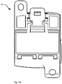
- the representations in Figure 3A , 4A and 5A correspond to the representations in Figure 3B , 4B and 5B , whereby in the representations in Figure 3B , 4B and 5B for a better overview the reference lines and reference numbers have been omitted.
- FIG. 3A , 3B shows an underside 12 of the assembly 10 according to FIG Figure 1 and Figure 2 .
- the assembly 10 is to be snapped onto a mounting rail 14 ( Fig. 6 ) intended.
- the underside 12 of the assembly 10 is configured accordingly and has a latching device in the form of at least one movable latching hook 20 and at least one rigid latching hook 22.
- the movable latching hook 20 and the or each rigid latching hook 22 are placed on the underside 12 of the assembly 10 opposite one another and facing one another. A distance between the movable latching hook 20 and the or each rigid latching hook 22 is adjusted to a width of the support rail 14.
- an embodiment of a locking device 20, 22 with exactly one movable locking hook 20 and exactly two rigid locking hooks 22 is shown. The following description is continued on this basis, but without renouncing any further general validity.
- an embodiment with more or less than two rigid locking hooks 22 or more than one movable locking hook 20 can always be read.
- the movable latching hook 20 can be seen at the foot of one of two opposite connection sides of the assembly 10.
- the side view shown on one side of the assembly 10 shows the movable latching hook 20 and a latching lug 24 of the movable latching hook 20 as well as a retaining lug 26 of one of the rigid latching hooks 22 lying opposite.
- the opposing arrangement of the movable latching hook 20 and the two rigid latching hooks 22 can also be clearly seen in the illustration of the underside 12 of the assembly 10. It is also evident there that the latching lug 24 of the movable latching hook 20 and the holding lugs 26 of the two rigid latching hooks 22 face one another.
- the support rail 14 is received in the free area remaining in between.
- the movable latching hook 20 is articulated to the underside 12 of the assembly 10 by means of an elastically movable latching hook web 30.
- the latching nose 24 adjoins the latching hook web 30 and is followed by a latching hook tab 32 intended for deflecting the movable latching hook 20.
- Limiting means 34, 35, 36, 37, 38 are provided to limit the mobility of the latching hook tab 32 when the movable latching hook 20 is deflected.
- the limiting means 34-38 are, on the one hand, at least one stop rib 34 oriented transversely to a longitudinal extension of the locking hook tab.
- two opposing stop ribs 34 are part of a contour of the underside 12 of the assembly 10.
- the locking hook tab 32 is located between these stop ribs 34 and has recesses 35 into which the stop ribs 34 engage, so that in each case one of the side surfaces of these recesses 35 abuts against the stop ribs 34 from a certain deflection of the movable locking hook 20 caused by a movement of the locking hook tab 32. Further movement of the latching hook tab 32 is then no longer possible.
- the movable latching hook 20 cannot then be deflected any further.
- the mobility of the latching hook tab 32 limits the possible deflection of the movable latching hook 20 as a whole.
- the position of the stop rib 34 and the recesses 35 can also be reversed in the sense of a kinematic reversal in such a way that the latching hook tab 32 has the stop rib 34 and the contour on the underside 12 of the assembly 10 has the recesses 35.
- the embodiment of the latching device 20, 22 shown includes at least one pair of guide ribs 36, 37 which are placed above and below a plane defined by the latching hook tab 32.
- the guide ribs 36, 37 are aligned parallel to the longitudinal extent of the latching hook tab 32 and enclose a section of the latching hook tab 32, here a lateral position 38 on the latching hook tab 32, also oriented parallel to the longitudinal extent of the latching hook tab 32.
- the guide ribs 36, 37 are part of a contour of the underside 12 of the assembly 10.
- the guide ribs 36, 37 which act as delimitation means and, if necessary, a storage 38 in the
- the guide ribs 36, 37 guide the locking hook tab 32 in the plane defined by the position and orientation of the guide ribs 36, 37, in the embodiment shown in a plane parallel to a plane of a mounting plate on which the support rail 14 is attached and on which in turn the assembly 10 is snapped on.
- the latching hook tab 32 of the movable latching hook 20 has a material-reduced section 40 between the latching hook 20 on the one hand and the recess 35 functioning as a limiting means on the other hand.
- the material-reduced section 40 there is an increased elastic deformability of the latching hook tab 32 in a manner that is fundamentally the case, for example, with a film hinge. Due to this elastic deformability, a purely translational movement of the latching hook tab 32 between the guide ribs 36, 37 when the movable latching hook 20 is deflected to release a latching of the assembly 10 on a support rail 14 is possible.
- FIG. 6 shows the assembly 10 according to the figures explained above in a cross-sectional side view and in a state latched onto a support rail 14 in the form of a top-hat rail.
- the profile of the support rail 14 is encompassed in a manner known per se on the one hand by the retaining lugs 26 of the two rigid latching hooks 22 and on the opposite side by the latching lug 24 of the movable latching hook 20.
- the latching hook tab 32 is moved in the direction indicated by the block arrow. This happens for example, by inserting a tool, in particular a blade of a screwdriver (not shown), into an opening 42 at the free end of the latching hook tab 32.
- the resulting movement of the latching hook tab 32 is a purely translational movement due to the guide ribs 36, 37 functioning as limiting means.
- the translational movement of the latching hook tab 32 leads to a pivoting of the movable latching hook 20, so that finally the latching lug 24 disengages from the support rail 14 and the latching of the assembly 10 on the support rail 14 is thus canceled.
- the translational mobility of the locking hook tab 32 is limited by the stop ribs 34 and the recesses 35 enclosing them on the side of the locking hook tab 32, so that the extent of the deflection of the movable locking hook 20 and thus the expansion of the material of the resulting when the movable locking hook 20 is deflected Rasthakenstegs 30 is limited. This protects the movable latching hook 20 even when excessive force is applied, so that the latching device 20, 22 formed therewith can be permanently loaded and used permanently.
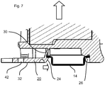
- FIG Figure 7 A tensile load (tensile force) acting on the assembly 10, for example due to an improper attempt to release the latching of the assembly 10 on the mounting rail 14, or due to vibration loads or the like, is shown in FIG Figure 7 illustrated by the upward-facing block arrow.
- the holding force can accordingly be represented as being composed of a first and a second force component.
- the first force component acts along the longitudinal extension of the inclined locking hook web 30.
- the second force component supplements the first force component in terms of magnitude and direction of the overall holding force.
- This second force component causes the locking hook web 30 to be pressed against the mounting rail 14 and the locking lug 24 to claw on the underside of the mounting rail 14. This is shown by the block arrow facing to the right in the area of the locking lug 24.
- a latching device 20, 22 for an electrical assembly 10 is specified, the latching device 20, 22 having a movable latching hook 20 articulated on the assembly 10 by means of an elastically movable latching hook web 30 and one for Deflecting the movable latching hook 20 comprises certain latching hook tab 32, and wherein limiting means 34, 35, 36, 37, 38 limit a mobility of the latching hook tab 32 when the movable latching hook 20 is deflected.
Landscapes
- Engineering & Computer Science (AREA)
- Power Engineering (AREA)
- Clamps And Clips (AREA)
- Mounting Components In General For Electric Apparatus (AREA)
- Casings For Electric Apparatus (AREA)
- Hooks, Suction Cups, And Attachment By Adhesive Means (AREA)
Description
- Die Erfindung betrifft zuvorderst eine Rastvorrichtung für eine elektrische Baugruppe oder ein elektrisches Gerät - im Folgenden zusammenfassend als elektrische Baugruppe bezeichnet. Als elektrische Baugruppe werden Klemmen, Verteilerklemmen oder sonstige elektrische Anschlussvorrichtungen, Sicherungshalter usw., aber auch Schaltgeräte wie Schütze, Motorschutzschalter und dergleichen verstanden. Im Weiteren betrifft die Erfindung auch eine derartige elektrische Baugruppe mit einer Rastvorrichtung.
- Bei derartigen Baugruppen ist eine Anbringung in einem Klemmkasten, Verteilerkasten oder einem sogenannten Schaltschrank üblich. Die Anbringung erfolgt auf oder an einer dafür vorgesehenen Trag- oder Montageschiene. Solche Schienen weisen ein für ein lösbares Anbringen (Aufrasten, Entrasten) einer Baugruppe oder einer Mehrzahl von Baugruppen vorgesehenes Profil auf. Ein Beispiel für ein derartiges Profil ist ein sogenanntes Hutprofil einer entsprechend als Hutprofilschiene oder kurz als Hutschiene bezeichneten Tragschiene.
- Die Anbringung jeweils einer Baugruppe auf oder an einer solchen Tragschiene erfolgt mittels eines von der jeweiligen Baugruppe umfassten Rastprofils und einer wiederum davon umfassten Rastvorrichtung. Das Rastprofil befindet sich auf einer Unterseite der Baugruppe und umfasst üblicherweise in einem auf die Breite der jeweiligen Tragschiene abgestellten Abstand auf einer Seite ein feststehendes Rastprofil, zum Beispiel in Form zumindest eines starren Rasthakens, und auf einer gegenüberliegenden Seite ein federndes Rastprofil, zum Beispiel in Form zumindest eines federnden Rasthakens. Ein derartiges Rastprofil ist in der
DE 20 2010 005 216 U1 mit dem Titel "Elektrische Anschlussvorrichtung" beschrieben. - Wenngleich sich das Rastprofil der
DE20 2010 005 216 U1 in der Praxis bewährt hat, besteht noch Verbesserungspotential. - Rastvorrichtungen sind in vielfältiger Form im Stand der Technik bekannt. Beispiele finden sich neben der vorgenannten
DE20 2010 005 216 U1 auch in derEP 0 602 305 A1 , derUS 6,563,697 , derJP H05 198332 A DE 20 2010 013 453 U1 , die eine Rastvorrichtung gemäß dem Oberbegriff des Anspruchs 1 offenbart, sowie derDE 10 2006 030 953 A1 . - Eine Aufgabe der vorliegenden Erfindung besteht entsprechend darin, eine weitere Ausführungsform eines Rastprofils, insbesondere eine weitere Ausführungsform einer Rastvorrichtung eines solchen Rastprofils, anzugeben.
- Diese Aufgabe wird erfindungsgemäß mittels einer Rastvorrichtung der eingangs genannten Art mit den Merkmalen des Anspruchs 1 gelöst. Dazu ist bei einer Rastvorrichtung für eine elektrische Baugruppe vorgesehen, dass die Rastvorrichtung einen Rasthaken sowie eine zum Auslenken des Rasthakens bestimmte Rasthakenlasche umfasst. Des Weiteren ist der Rasthaken an einer Seitenfläche der Baugruppe, üblicherweise der Unterseite, mittels eines elastisch beweglichen Rasthakenstegs angelenkt. Aufgrund des elastisch beweglichen Rasthakenstegs ist der Rasthaken damit selbst elastisch beweglich und wird im Folgenden zur Unterscheidung von zumindest einem gegenüberliegend angeordneten starren Rasthaken als beweglicher Rasthaken bezeichnet. Die Rastvorrichtung weist des Weiteren Begrenzungsmittel auf, die eine Beweglichkeit der Rasthakenlasche beim Auslenken des Rasthakens begrenzen.
- Die Rastvorrichtung der
DE 20 2010 013 453 U1 weist einen Rasthaken, eine zum Auslenken des Rasthakens bestimmte und dort als Rastfuß bezeichnete Rasthakenlasche sowie zwei den Rastfuß haltende, elastisch bewegliche Rasthakenstege auf. Die Rastvorrichtung derDE 20 2010 013 453 U1 umfasst ferner in Form einer Anschlagfläche eines von dem Rastfuß unabhängigen Anschlags Begrenzungsmittel, welche eine Beweglichkeit des Rastfußes beim Auslenken des Rasthakens begrenzen. Einer der Rasthakenstege der Rastvorrichtung derDE 20 2010 013 453 U1 ist gegen eine Normale geneigt und die Richtung der Neigung ist von einer zu kontaktierenden Tragschiene abgewandt. - Bei der
DE 20 2010 005 216 U1 fungiert als Rastvorrichtung ein federnder Rasthaken. Zum Fixieren einer mit einer solchen Rastvorrichtung ausgestatteten Baugruppe an einer Tragschiene wird diese einseitig an der Tragschiene eingehängt und durch anschließendes Verschwenken in Richtung auf die Tragschiene an dieser verrastet. Dabei wird der federnde Rasthaken beim Kontaktmit der Tragschiene im Rahmen seiner Materialelastizität ausgelenkt. Im vollständig verschwenkten Zustand der Baugruppe federt der Rasthaken zurück in seine Ursprungsposition und greift mit seiner hakenförmigen Kontur (Rastnase) unter einen Abschnitt der Tragschiene. Zum Abnehmen einer an einer Tragschiene verrasteten und mit einer derartigen Rastvorrichtung ausgestatteten Baugruppe wird der federnde Rasthaken mittels eines Werkzeugs, üblicherweise eines Schraubendrehers, ausgelenkt, so dass die Rastnase des Rasthakens außer Eingriff mit der Tragschiene kommt, woraufhin sich die Baugruppe von der Tragschiene entfernen lässt. - Die federnde Eigenschaft eines solchen Rasthakens ergibt sich aufgrund eines mit einem Gehäuse der jeweiligen Baugruppe verbundenen, insbesondere einstückig verbundenen Rasthakenstegs und dessen Materialeigenschaften. Üblicherweise sind Gehäuse der hier betroffenen Baugruppen aus einem Kunststoff gefertigt und entsprechend ist auch der als Anbindung des Rasthakens an das Gehäuse (Rasthakenanbindung) fungierende Rasthakensteg üblicherweise aus einem Kunststoff gefertigt. Im Rahmen der Materialeigenschaften des jeweils verwendeten Kunststoffs ergibt sich eine federnde Eigenschaft des Rasthakenstegs. Bei übermäßiger Kraftanwendung kann ein solcher Rasthakensteg allerdings durchaus ganz oder teilweise brechen, so dass bei einem abgerissenen Rasthakensteg keine Verrastung der jeweiligen Baugruppe an einer Tragschiene mehr möglich ist und bei einem teilweise gebrochenen oder überlasteten Rasthakensteg die federnde Eigenschaft oftmals so weit herabgesetzt ist, dass beim Aufschwenken der jeweiligen Baugruppe auf die Tragschiene der Rasthakensteg nicht mehr in eine Konfiguration zurückfedert, in welcher die am Ende des Rasthakens befindliche Rastnase sicher unter die Tragschiene greift.
- Bei der hier vorgeschlagenen Rastvorrichtung ist der Rasthakensteg zumindest abschnittsweise geneigt. Die Neigung besteht gegenüber einer Normalen der jeweiligen Seitenfläche, von welcher der Rasthakensteg ausgeht, also üblicherweise gegenüber einer Normalen der Unterseite der Baugruppe. Die Richtung der Neigung ist dabei von dem Bereich zwischen dem beweglichen Rasthaken und zumindest einem gegenüberliegenden starren Rasthaken abgewandt. In diesem Bereich befindet sich bei einer aufgerasteten Baugruppe die Tragschiene. Diese Richtung der Neigung wird entsprechend im Folgenden kurz als eine von der Tragschiene abgewandte Neigung bezeichnet. Indem der Rasthakensteg zumindest abschnittsweise derart geneigt ist, ergibt sich eine bessere Belastbarkeit der Rastverbindung. Die verbesserte Belastbarkeit ist gegeben, weil sich bei einer Zugbelastung, welche auf eine an einer Tragschiene verrastete Baugruppe wirkt, der geneigte Rasthakensteg aufgrund der Zugbelastung mehr und mehr aufrichtet. Dieses Aufrichten führt zu einer verbesserten und belastbareren Verrastung der Baugruppe an der Tragschiene:
Bei bisherigen Rastvorrichtungen ist eine als Rasthakensteg auffassbare Verbindung zwischen dem Gehäuse der Baugruppe und dem beweglichen Rasthaken regelmäßig senkrecht zur Unterseite der Baugruppe ausgerichtet. Bei einer auf die Baugruppe wirkenden erheblichen Zugbelastung wird ein solcher Rasthakensteg gedehnt. Diese Dehnung ist innerhalb des Rasthakenstegs nicht gleichmäßig, sondern auf einer der Tragschiene oder dem oder jedem starren Rasthaken zugewandten Seite (derjenigen Seite, welcher die Rastnase am beweglichen Rasthaken zugewandt ist) am größten. Dies führt zu einer Deformation des Rasthakenstegs, welche einen Abstand zwischen der Rastnase am beweglichen Rasthaken und einer entsprechenden Rastkontur an dem oder jedem gegenüberliegenden starren Rasthaken vergrößert, so dass die Rastnase des beweglichen Rasthakens schließlich außer Eingriff mit der Tragschiene kommt. Dann besteht die Verrastung der Baugruppe an der Tragschiene nicht mehr. Bei dem geneigten Rasthakensteg gemäß der hier vorgeschlagenen Ausführungsform der Rastvorrichtung mit der von der Tragschiene abgewandten Neigung führt eine auf die Baugruppe wirkende erhebliche Zugbelastung möglicherweise ebenfalls zu einer Dehnung des Rasthakenstegs, aber zumindest auch zu einem Aufrichten des Rasthakenstegs aus der zuvor geneigten Orientierung. In der unbelasteten geneigten Ausrichtung ist ein Abstand zwischen der Rastnase des beweglichen Rasthakens und einer entsprechenden Rastkontur an dem oder jedem gegenüberliegenden starren Rasthaken auf die Breite der Tragschiene abgestimmt. Beim Aufrichten des Rasthakenstegs wird dieser an die Tragschiene gepresst. Zunehmende Zugbelastung führt also gerade dazu, dass der Rasthaken immer stärker seitlich an die Tragschiene gepresst wird, so dass sich die Rastnase unter der Tragschiene gewissermaßen verkrallt und die Rastnase gerade nicht außer Eingriff mit der Tragschiene kommt. - Im Ergebnis ist die Fixierung der jeweiligen Baugruppe im verrasteten Zustand an der Tragschiene damit deutlich belastbarer, und zwar belastbarer gegen Rüttelbelastungen, auch außergewöhnliche Rüttelbelastungen, sowie belastbarer gegen unsachgemäße Versuche, die Verrastung der Baugruppe an der Tragschiene zu lösen.
- Der Vorteil der hier vorgeschlagenen Rastvorrichtung besteht weiterhin darin, dass eine zum Auslenken des Rasthakens bestimmte Rasthakenlasche durch Begrenzungsmittel geführt wird und dass diese Führung der Rasthakenlasche eine Beweglichkeit der Rasthakenlasche beim Auslenken des Rasthakens begrenzt und damit auch eine Beweglichkeit des Rasthakens insgesamt begrenzt.
- Die Begrenzung der Beweglichkeit des Rasthakens bewirkt, dass der Rasthaken auch bei übermäßiger Kraftanwendung nicht beschädigt oder gar abgerissen werden kann. Die Begrenzung der Beweglichkeit des Rasthakens bewirkt zudem, dass der Rasthakensteg beim Auslenken des Rasthakens nicht überbeansprucht (überdehnt) wird und dieser damit die im Rahmen der jeweiligen Materialeigenschaften gegebene Elastizität auch nach einer Vielzahl von Rastvorgängen sowie einer jeweils anschließenden Lösung der Rastverbindung behält. Dabei ist die Rastvorrichtung kostengünstig, denn sie kann aus dem Werkstoff des Gehäuses der jeweiligen Baugruppe gefertigt und einstückig mit dem Gehäuse verbunden sein. Die Rastvorrichtung ist bei einer solchen Ausführungsform integraler Bestandteil des Gehäuses der jeweiligen Baugruppe und erfordert beim Herstellen der jeweiligen Baugruppe keinen zusätzlichen Montageschritt.
- Vorteilhafte Ausgestaltungen der Rastvorrichtung sind Gegenstand der Unteransprüche. Dabei verwendete Rückbeziehungen weisen auf die weitere Ausbildung des Gegenstandes des Hauptanspruches durch die Merkmale des jeweiligen Unteranspruches hin. Sie sind nicht als ein Verzicht auf die Erzielung eines selbständigen, gegenständlichen Schutzes für die Merkmalskombinationen der rückbezogenen Unteransprüche zu verstehen. Des Weiteren ist im Hinblick auf eine Auslegung der Ansprüche bei einer näheren Konkretisierung eines Merkmals in einem nachgeordneten Anspruch davon auszugehen, dass eine derartige Beschränkung in den jeweils vorangehenden Ansprüchen nicht vorhanden ist.
- Bei einer weiteren Ausführungsform der Rastvorrichtung fungiert als Begrenzungsmittel zumindest eine quer zu einer Längserstreckung der Rasthakenlasche orientierte Anschlagsrippe. Die Anschlagsrippe bewirkt, dass die Rasthakenlasche nur bis zum Anschlag an der Anschlagsrippe beweglich ist. Diese Beschränkung der Beweglichkeit der Rasthakenlasche bewirkt eine Beschränkung der Auslenkbarkeit des Rasthakens und des Rasthakenstegs. Die zumindest eine Anschlagrippe ist demnach ein Beispiel für eine Beschränkung der Beweglichkeit des elastisch verformbaren Rasthakenstegs, welche gewährleistet, dass der Rasthakensteg weder abgerissen werden kann noch derart überbeansprucht werden kann, dass dessen elastische Verformbarkeit und damit dessen federnde Eigenschaft verlorengeht. Die Anschlagrippe kann Teil der Rasthakenlasche sein und an einer dafür vorgesehenen Kontur an der Unterseite der jeweiligen Baugruppe anschlagen. Alternativ kann die Anschlagsrippe auch Teil der Kontur der Unterseite der jeweiligen Baugruppe sein und in eine Ausnehmung in der Rasthakenlasche eingreifen und zur Begrenzung von dessen Beweglichkeit an einer Seitenfläche dieser Ausnehmung anschlagen.
- Bei einer weiteren oder alternativen Ausführungsform der Rastvorrichtung fungieren als Begrenzungsmittel zumindest ein Paar Führungsrippen, welche ober- und unterhalb einer durch die Rasthakenlasche definierten Ebene platziert sind. Die Führungsrippen gewährleisten, dass die Rasthakenlasche beim Auslenken des Rasthakens in einer durch die Position der Führungsrippen definierten Ebene geführt wird. Indem die Führungsrippen selbst ober- und unterhalb der durch die Rasthakenlasche definierten Ebene angebracht sind, verbleibt die Rasthakenlasche beim Auslenken des Rasthakens stets in derselben oder zumindest im Wesentlichen in derselben Ebene. Damit kann die Rasthakenlasche beim Auslenken des Rasthakens nicht aus der für eine translatorische Bewegung der Rasthakenlasche vorgesehenen Ebene verschwenkt und zum Beispiel nicht hochgeklappt und damit verbogen oder abgebrochen werden. Auf diese Weise ist gewährleistet, dass die Rasthakenlasche auch beim mehrfachen Lösen der Rastverbindung nicht beschädigt wird und somit ebenfalls gewährleistet, dass die Rastvorrichtung insgesamt dauerhaft verwendbar bleibt. Darüber hinaus erleichtert die Fixierung der Rasthakenlasche in der durch die Führungsrippen definierten Ebene die Bedienung der Rastvorrichtung beim Auflösen der Rastverbindung, denn aufgrund der Führungsrippen befindet sich die Rasthakenlasche immer leicht oberhalb von zum Beispiel einer Montageplatte oder dergleichen, auf welcher die jeweilige Tragschiene montiert ist, an welcher die Baugruppe verrastet ist. Dort kann die Rasthakenlasche mit einem Werkzeug, zum Beispiel einem Schraubendreher, leicht erfasst werden, zum Beispiel indem die Klinge des Schraubendrehers in eine dafür vorgesehene Ausnehmung am freien Ende der Rasthakenlasche eingeführt wird. Ohne die Fixierung der Rasthakenlasche in der durch die Führungsrippen definierten Ebene kann die Rasthakenlasche nach mehreren Betätigungsvorgängen gewissermaßen nach oben geklappt (von einer eventuellen Montageplatte weg) oder nach unten gedrückt sein und im nach unten gedrückten Zustand auf der Montageplatte aufliegen. Dort kann die Klinge des Schraubendrehers nur bis zum Kontakt mit der Montageplatte in die Ausnehmung am Ende der Rasthakenlasche eingeführt werden. Dies erhöht die Gefahr, dass die Klinge des Schraubendrehers beim Bewegen der Rasthakenlasche abrutscht. Zudem kann durch den Kontakt der Klinge des Schraubendrehers mit der Montageplatte diese verkratzen.
- Erfindungsgemäß weist die Rasthakenlasche entlang ihrer Längserstreckung einen materialreduzierten Abschnitt auf. In dem materialreduzierten Abschnitt ist die Rasthakenlasche dünner als seitlich neben dem materialreduzierten Abschnitt. Der materialreduzierte Abschnitt gewährleistet in diesem Bereich eine elastische Beweglichkeit der Rasthakenlasche quer zu dessen Längserstreckung. Beim Auslenken des Rasthakens findet nicht nur eine elastische Verformung des Rasthakens im Bereich von dessen Rasthakensteg, sondern auch eine elastische Verformung der Rasthakenlasche im Bereich von deren materialreduziertem Abschnitt statt. Damit kann die Rasthakenlasche der beim Betätigen der Rasthakenlasche ausgelösten Schwenkbewegung des Rasthakenstegs optimal folgen, indem die Rasthakenlasche in dem materialreduzierten Abschnitt mehr und mehr abknickt, je mehr der Rasthakensteg verschwenkt wird. Der an den materialreduzierten Abschnitt bis zum freien Ende der Rasthakenlasche anschließende Teil bleibt dabei in seiner vorgesehenen horizontalen oder im Wesentlichen horizontalen Ausrichtung.
- Eine solche horizontale oder im Wesentlichen horizontale Ausrichtung der Rasthakenlasche lässt sich besonders gut gewährleisten, wenn sich der materialreduzierte Abschnitt der Rasthakenlasche zwischen dem Rasthaken und dem Begrenzungsmittel oder einem Begrenzungsmittel befindet.
- Insgesamt ist die hier vorgeschlagene Neuerung auch eine elektrische Baugruppe der eingangs genannten Art mit einer Rastvorrichtung wie hier und im Folgenden beschrieben.
- Nachfolgend wird ein Ausführungsbeispiel der erfindungsgemäßen Rastvorrichtung anhand der Zeichnung näher erläutert. Einander entsprechende Gegenstände oder Elemente sind in allen Figuren mit den gleichen Bezugszeichen versehen.
- Es zeigen
- Fig. 1
- eine zum Aufrasten auf eine Tragschiene vorgesehene elektrische Baugruppe in perspektivischer Ansicht,
- Fig. 2
- die Baugruppe gemäß
Fig. 1 in einer Seitenansicht, - Fig. 3A, 3B
- eine Unterseite der Baugruppe gemäß
Fig. 1 und Fig. 2 mit einem dort zum Aufrasten der Baugruppe auf einer Tragschiene gebildeten Rastprofil, - Fig. 4A, 4B
- eine Ausschnittsvergrößerung aus der Darstellung in
Fig. 1 , - Fig. 5A, 5B
- eine vergrößerte Darstellung der Unterseite der Baugruppe in perspektivischer Ansicht und
- Fig. 6
- einen Schnitt durch die Baugruppe gemäß
Fig. 1 und Fig. 2 in einer Seitenansicht im an einer Tragschiene aufgerasteten Zustand sowie - Fig. 7
- einen Ausschnitt aus der Darstellung in
Fig. 6 . - Die Darstellungen in
Figur 1 und Figur 2 zeigen als Beispiel für eine elektrische Baugruppe 10 der hier in Rede stehenden Art einen Verteilerblock/eine Verteilerklemme ähnlich der in derDE 20 2010 005 216 U1 beschriebenen Verteilerklemme. Die Darstellungen inFigur 3A ,4A und 5A entsprechen den Darstellungen inFigur 3B ,4B und 5B , wobei in den Darstellungen inFigur 3B ,4B und 5B zur besseren Übersicht die Bezugslinien und Bezugsziffern weggelassen sind. - Die Darstellung in
Figur 3A ,3B zeigt eine Unterseite 12 der Baugruppe 10 gemäßFigur 1 und Figur 2 . Die Baugruppe 10 ist zum Aufrasten auf eine Tragschiene 14 (Fig. 6 ) vorgesehen. Zu diesem Zweck ist die Unterseite 12 der Baugruppe 10 entsprechend ausgestaltet und weist eine Rastvorrichtung in Form von zumindest einem beweglichen Rasthaken 20 und zumindest einem starren Rasthaken 22 auf. Der bewegliche Rasthaken 20 und der oder jeder starre Rasthaken 22 sind an der Unterseite 12 der Baugruppe 10 gegenüberliegend und einander zugewandt platziert. Ein Abstand zwischen dem beweglichen Rasthaken 20 und dem oder jedem starren Rasthaken 22 ist auf eine Breite der Tragschiene 14 abgestellt. - In den Figuren ist eine Ausführungsform einer Rastvorrichtung 20, 22 mit genau einem beweglichen Rasthaken 20 und genau zwei starren Rasthaken 22 gezeigt. Auf dieser Basis, allerdings ohne Verzicht auf eine weitergehende Allgemeingültigkeit, wird die nachfolgende Beschreibung fortgesetzt. Entsprechend ist eine Ausführungsform mit mehr oder weniger als zwei starren Rasthaken 22 oder mehr als einem beweglichen Rasthaken 20 stets mitzulesen. Grundsätzlich kommt zum Beispiel auch eine Ausführungsform mit zwei einander gegenüberliegenden beweglichen Rasthaken 20 in Betracht. Auch dies ist im Folgenden stets mitzulesen.
- In der isometrischen Ansicht der Baugruppe 10 gemäß
Figur 1 ist der bewegliche Rasthaken 20 am Fuß einer von zwei einander gegenüberliegenden Anschlussseiten der Baugruppe 10 erkennbar. In der inFigur 2 gezeigten Seitenansicht sind auf einer Seite der Baugruppe 10 der bewegliche Rasthaken 20 und eine Rastnase 24 des beweglichen Rasthakens 20 sowie eine Haltenase 26 eines der gegenüberliegenden starren Rasthaken 22 erkennbar. Die einander gegenüberliegende Anordnung des beweglichen Rasthakens 20 und der beiden starren Rasthaken 22 ist auch in der Darstellung der Unterseite 12 der Baugruppe 10 gut erkennbar. Dort wird auch offenbar, dass die Rastnase 24 des beweglichen Rasthakens 20 und die Haltenasen 26 der beiden starren Rasthaken 22 einander zugewandt sind. In dem dazwischen verbleibenden freien Bereich wird die Tragschiene 14 aufgenommen. - Die nachfolgenden Ausführungen befassen sich mit dem von der Rastvorrichtung 20, 22 umfassten beweglichen Rasthaken 20. Dafür wird auf die in Figur 4A, 4B gezeigte Ausschnittsvergrößerung aus der Darstellung in
Figur 1 sowie eine vergrößerte perspektivische Darstellung der Unterseite 12 der Baugruppe 10 inFigur 5A ,5B verwiesen. - Speziell in der Darstellung in
Figur 5A ,5B ist gut erkennbar, dass der bewegliche Rasthaken 20 mittels eines elastisch beweglichen Rasthakenstegs 30 an der Unterseite 12 der Baugruppe 10 angelenkt ist. An den Rasthakensteg 30 schließt sich die Rastnase 24 an und an diese eine zum Auslenken des beweglichen Rasthakens 20 bestimmte Rasthakenlasche 32. - Zur Begrenzung einer Beweglichkeit der Rasthakenlasche 32 beim Auslenken des beweglichen Rasthakens 20 sind Begrenzungsmittel 34, 35, 36, 37, 38 vorgesehen.
- Bei der gezeigten Ausführungsform der Rastvorrichtung 20, 22 (siehe auch
Fig: 3 ) handelt es sich bei den Begrenzungsmitteln 34-38 zum einen um zumindest eine quer zu einer Längserstreckung der Rasthakenlasche orientierte Anschlagsrippe 34. Bei der gezeigten Ausführungsform sind zwei einander gegenüberliegend platzierte Anschlagsrippen 34 Teil einer Kontur der Unterseite 12 der Baugruppe 10. Die Rasthakenlasche 32 befindet sich zwischen diesen Anschlagsrippen 34 und weist Ausnehmungen 35 auf, in welche die Anschlagsrippen 34 eingreifen, so dass jeweils eine der Seitenflächen dieser Ausnehmungen 35 ab einer bestimmten mittels einer Bewegung der Rasthakenlasche 32 veranlassten Auslenkung des beweglichen Rasthakens 20 an den Anschlagsrippen 34 anschlägt. Eine weitere Bewegung der Rasthakenlasche 32 ist dann nicht mehr möglich. Entsprechend kann dann auch der bewegliche Rasthaken 20 nicht weiter ausgelenkt werden. Insofern beschränkt die Beweglichkeit der Rasthakenlasche 32 die mögliche Auslenkung des beweglichen Rasthakens 20 insgesamt. Wie bereits im allgemeinen Beschreibungsteil ausgeführt, kann die Position der Anschlagsrippe 34 und der Ausnehmungen 35 im Sinne einer kinematischen Umkehr auch derart vertauscht sein, dass die Rasthakenlasche 32 die Anschlagsrippe 34 und die Kontur auf der Unterseite 12 der Baugruppe 10 die Ausnehmungen 35 aufweist. - Neben den Begrenzungsmitteln in Form der Anschlagsrippe 34 und der Ausnehmungen 35 umfasst die gezeigte Ausführungsform der Rastvorrichtung 20, 22 zumindest ein Paar Führungsrippen 36, 37, welche ober- und unterhalb einer durch die Rasthakenlasche 32 definierten Ebene platziert sind. Die Führungsrippen 36, 37 sind parallel zur Längserstreckung der Rasthakenlasche 32 ausgerichtet und fassen einen Abschnitt der Rasthakenlasche 32, hier eine ebenfalls parallel zur Längserstreckung der Rasthakenlasche 32 orientierte seitliche Abstellung 38 an der Rasthakenlasche 32, ein. Die Führungsrippen 36, 37 sind Teil einer Kontur der Unterseite 12 der Baugruppe 10. Wie zuvor bezüglich der Anschlagsrippe 34 und der zur Aufnahme der Anschlagsrippe 34 bestimmten Ausnehmung 35 erläutert, ist auch bei den als Begrenzungsmittel fungierenden Führungsrippen 36, 37 sowie gegebenenfalls einer Abstellung 38 im Sinne einer kinematischen Umkehr eine Zuordnung der Abstellung 38 zur Unterseite 12 der Baugruppe 10 sowie eine Zuordnung der Führungsrippen 36, 37 zur Rasthakenlasche 32 möglich. Die Führungsrippen 36, 37 bewirken eine Führung der Rasthakenlasche 32 in der durch die Position und Orientierung der Führungsrippen 36, 37 definierten Ebene, beim gezeigten Ausführungsbeispiel in einer Ebene parallel zu einer Ebene einer Montageplatte, an welcher die Tragschiene 14 angebracht ist und auf welcher wiederum die Baugruppe 10 aufgerastet wird. Mittels der Führung der Rasthakenlasche 32 in der durch die Führungsrippen 36, 37 definierten Ebene ist gewährleistet, dass die Rasthakenlasche 32 - kurz gefasst - nicht umgebogen werden kann. Diese Führung der Rasthakenlasche 32 schützt auch den beweglichen Rasthaken 20 und dessen Rasthakensteg 30 vor Beschädigungen.
- Bei der in den Figuren gezeigten Ausführungsform weist die Rasthakenlasche 32 des beweglichen Rasthakens 20 zwischen dem Rasthaken 20 einerseits und der als Begrenzungsmittel fungierenden Ausnehmung 35 andererseits einen materialreduzierten Abschnitt 40 auf. Im Bereich des materialreduzierten Abschnitts 40 ergibt sich eine erhöhte elastische Verformbarkeit der Rasthakenlasche 32 in einer Art und Weise, wie dies grundsätzlich zum Beispiel bei einem Filmscharnier der Fall ist. Aufgrund dieser elastischen Verformbarkeit ist eine rein translatorische Bewegung der Rasthakenlasche 32 zwischen den Führungsrippen 36, 37 beim Auslenken des beweglichen Rasthakens 20 zum Auflösen einer Verrastung der Baugruppe 10 an einer Tragschiene 14 möglich.
- Die Darstellung in
Figur 6 zeigt die Baugruppe 10 gemäß der vorangehend erläuterten Figuren in einer quergeschnittenen Seitenansicht und in einem auf einer Tragschiene 14 in Form einer Hutschiene aufgerasteten Zustand. Das Profil der Tragschiene 14 wird in grundsätzlich an sich bekannter Art und Weise auf der einen Seite durch die Haltenasen 26 der beiden starren Rasthaken 22 und auf der gegenüberliegenden Seite durch die Rastnase 24 des beweglichen Rasthakens 20 umfasst. Zum Auflösen der Verrastung wird die Rasthakenlasche 32 in der durch den Blockpfeil angedeuteten Richtung bewegt. Dies erfolgt beispielsweise, indem ein Werkzeug, insbesondere eine Klinge eines Schraubendrehers (nicht gezeigt), in eine Öffnung 42 am freien Ende der Rasthakenlasche 32 eingeführt wird. Die resultierende Bewegung der Rasthakenlasche 32 ist aufgrund der als Begrenzungsmittel fungierenden Führungsrippen 36, 37 eine rein translatorische Bewegung. - Die translatorische Bewegung der Rasthakenlasche 32 führt zu einem Verschwenken des beweglichen Rasthakens 20, so dass schließlich die Rastnase 24 außer Eingriff mit der Tragschiene 14 kommt und somit die Verrastung der Baugruppe 10 an der Tragschiene 14 aufgehoben ist. Die translatorische Beweglichkeit der Rasthakenlasche 32 ist dabei durch die Anschlagsrippen 34 und die diese auf Seiten der Rasthakenlasche 32 einfassenden Ausnehmungen 35 begrenzt, so dass auch der Umfang der Auslenkung des beweglichen Rasthakens 20 und damit die beim Auslenken des beweglichen Rasthakens 20 resultierende Dehnung des Materials des Rasthakenstegs 30 begrenzt ist. Dies schützt den beweglichen Rasthaken 20 selbst bei übermäßiger Kraftanwendung, so dass die damit gebildete Rastvorrichtung 20, 22 dauerhaft belastbar und dauerhaft verwendbar ist.
- In den Darstellungen in
Figur 5 undFigur 6 ist auch die zumindest abschnittsweise Neigung des Rasthakenstegs 30 gegen eine Normale der Unterseite 12 der Baugruppe 10 erkennbar. Bei einer auf die Baugruppe 10 wirkenden Rüttel- oder Zugbelastung führt diese Neigung zu der im allgemeinen Beschreibungsteil erläuterten verbesserten Belastbarkeit der Rastverbindung, wie dies in der abschließenden Darstellung inFigur 7 veranschaulicht ist. Eine auf die Baugruppe 10 wirkende Zugbelastung (Zugkraft), zum Beispiel aufgrund eines unsachgemäßen Versuchs, die Verrastung der Baugruppe 10 an der Tragschiene 14 zu lösen, oder aufgrund von Rüttelbelastungen oder dergleichen, ist in der Darstellung inFigur 7 durch den aufwärtsgewandten Blockpfeil veranschaulicht. Aufgrund einer solchen Zugbelastung richtet sich der Rasthakensteg 30 aus seiner geneigten Position mehr und mehr in eine senkrechte Position auf. Dies führt dazu, dass der Rasthakensteg 30 und die an dessen Ende befindliche Rastnase 24 noch stärker an die angrenzende Struktur der Tragschiene 14 gepresst werden. Dieses Anpressen an die Tragschiene 14 ist als Ergebnis einer Zerlegung einer der Zugkraft entgegenwirkenden und der Zugkraft betragsmäßig entsprechenden Haltekraft erklärbar: Aufgrund der geneigten Position des Rasthakenstegs 30 schließen die Richtung der Haltekraft und der Rasthakensteg 30 einen Winkel ein. Die Haltekraft kann demgemäß als aus einer ersten und einer zweiten Kraftkomponente zusammengesetzt dargestellt werden. Die erste Kraftkomponente wirkt entlang der Längserstreckung des geneigten Rasthakenstegs 30. Die zweite Kraftkomponente ergänzt in einem Kräfteparallelogramm die erste Kraftkomponente nach Betrag und Richtung zur insgesamt wirkenden Haltekraft. Diese zweite Kraftkomponente bewirkt das Anpressen des Rasthakenstegs 30 an die Tragschiene 14 und das Verkrallen der Rastnase 24 an der Unterseite der Tragschiene 14. Dies ist durch den nach rechts gewandten Blockpfeil im Bereich der Rastnase 24 gezeigt. - Damit lässt sich die hier vorgelegte Beschreibung kurz wie folgt zusammenfassen: Es wird eine Rastvorrichtung 20, 22 für eine elektrische Baugruppe 10 angegeben, wobei die Rastvorrichtung 20, 22 einen an der Baugruppe 10 mittels eines elastisch beweglichen Rasthakenstegs 30 angelenkten beweglichen Rasthaken 20 und eine zum Auslenken des beweglichen Rasthakens 20 bestimmte Rasthakenlasche 32 umfasst, und wobei Begrenzungsmittel 34, 35, 36, 37, 38 eine Beweglichkeit der Rasthakenlasche 32 beim Auslenken des beweglichen Rasthakens 20 begrenzen.
-
- 10
- elektrische Baugruppe
- 12
- Unterseite
- 14
- Tragschiene
- 16, 18
- (frei)
- 20
- Rastvorrichtung, beweglicher Rasthaken
- 22
- Rastvorrichtung, starrer Rasthaken
- 24
- Rastnase
- 26
- Haltenase
- 28
- (frei)
- 30
- Rasthakensteg
- 32
- Rasthakenlasche
- 34
- Begrenzungsmittel, Anschlagsrippe
- 35
- Begrenzungsmittel, Ausnehmung
- 36
- Begrenzungsmittel, (obere) Führungsrippe
- 37
- Begrenzungsmittel, (untere) Führungsrippe
- 38
- Begrenzungsmittel, Abstellung
- 40
- materialreduzierter Abschnitt
- 42
- Öffnung
Claims (4)
- Rastvorrichtung (20, 22) für eine elektrische Baugruppe (10),
wobei die Rastvorrichtung (20, 22) einen an der Baugruppe (10) mittels eines elastisch beweglichen Rasthakenstegs (30) angelenkten Rasthaken (20) und eine zum Auslenken des Rasthakens (20) bestimmte Rasthakenlasche (32) umfasst,
wobei Begrenzungsmittel (34, 35, 36, 37, 38) eine Beweglichkeit der Rasthakenlasche (32) beim Auslenken des Rasthakens (20) begrenzen,
wobei der Rasthakensteg (30) zumindest abschnittsweise gegen eine Normale geneigt ist,
wobei eine Richtung der Neigung des Rasthakenstegs (30) von einer mittels der Rastvorrichtung (20, 22) kontaktierbaren Tragschiene (14) sowie einem Bereich zwischen dem beweglichen Rasthaken (20) und zumindest einem gegenüberliegenden starren Rasthaken (22) abgewandt ist,
so dass zunehmende Zugbelastung des Rasthakenstegs (30) dazu führt, dass der Rasthaken (20) immer stärker seitlich an die Tragschiene (14) gepresst wird,
dadurch gekennzeichnet,
dass die Rasthakenlasche (32) zwischen dem Rasthaken (20) und dem oder einem Begrenzungsmittel (34, 35, 36, 37, 38) einen materialreduzierten Abschnitt (40) aufweist,
dass der materialreduzierte Abschnitt (40) eine elastische Beweglichkeit der Rasthakenlasche (32) quer zu deren Längserstreckung gewährleistet. - Rastvorrichtung (20, 22) nach Anspruch 1, wobei als Begrenzungsmittel (34, 35, 36, 37, 38) zumindest eine quer zu einer Längserstreckung der Rasthakenlasche (32) orientierte Anschlagsrippe (34) fungiert.
- Rastvorrichtung (20, 22) nach einem der vorangehenden Ansprüche, wobei als Begrenzungsmittel (34, 35, 36, 37, 38) zumindest ein Paar ober- und unterhalb einer durch die Rasthakenlasche (32) definierten Ebene platzierte Führungsrippen (36, 37) fungieren.
- Elektrische Baugruppe (10) mit einer Rastvorrichtung (20, 22) nach einem der vorangehenden Ansprüche.
Applications Claiming Priority (2)
| Application Number | Priority Date | Filing Date | Title |
|---|---|---|---|
| DE202016100467.5U DE202016100467U1 (de) | 2016-01-30 | 2016-01-30 | Rastvorrichtung für eine elektrische Baugruppe und Baugruppe mit einer Rastvorrichtung |
| PCT/EP2017/051261 WO2017129499A1 (de) | 2016-01-30 | 2017-01-22 | Rastvorrichtung für eine elektrische baugruppe und baugruppe mit einer rastvorrichtung |
Publications (2)
| Publication Number | Publication Date |
|---|---|
| EP3408894A1 EP3408894A1 (de) | 2018-12-05 |
| EP3408894B1 true EP3408894B1 (de) | 2021-03-24 |
Family
ID=55974186
Family Applications (1)
| Application Number | Title | Priority Date | Filing Date |
|---|---|---|---|
| EP17702031.0A Active EP3408894B1 (de) | 2016-01-30 | 2017-01-22 | Rastvorrichtung für eine elektrische baugruppe und baugruppe mit einer rastvorrichtung |
Country Status (6)
| Country | Link |
|---|---|
| US (1) | US10574034B2 (de) |
| EP (1) | EP3408894B1 (de) |
| CN (1) | CN108886208B (de) |
| DE (1) | DE202016100467U1 (de) |
| ES (1) | ES2865270T3 (de) |
| WO (1) | WO2017129499A1 (de) |
Families Citing this family (2)
| Publication number | Priority date | Publication date | Assignee | Title |
|---|---|---|---|---|
| DE202016102088U1 (de) | 2016-04-20 | 2016-05-06 | Hora-Werk Gmbh | Rastprofil für eine elektrische Baugruppe und Baugruppe mit einem Rastprofil |
| CN112636395B (zh) * | 2020-12-11 | 2021-08-20 | 珠海市中力电力设备有限公司 | 一种用于智能分布式配网自动化终端的交互实现方法 |
Citations (1)
| Publication number | Priority date | Publication date | Assignee | Title |
|---|---|---|---|---|
| DE202010013453U1 (de) * | 2010-09-23 | 2010-11-25 | Wago Verwaltungsgesellschaft Mbh | Rastmodul |
Family Cites Families (10)
| Publication number | Priority date | Publication date | Assignee | Title |
|---|---|---|---|---|
| EP0300065B1 (de) * | 1987-07-18 | 1992-09-02 | Weidmüller Interface GmbH & Co. | Montagefuss zum Befestigen von elektrisch/elektronischen Bauelementen auf Tragschienen |
| JPH05198332A (ja) | 1992-01-21 | 1993-08-06 | Sharp Corp | ケースの取付構造 |
| ES2056035T3 (es) * | 1992-12-17 | 1996-03-16 | Ellenberger & Poensgen | Aparato de instalacion fijable en un carril de soporte. |
| DE29821558U1 (de) | 1998-12-04 | 1999-03-04 | Weidmüller Interface GmbH & Co., 32758 Detmold | Schutzleiterklemme |
| EP1058360B1 (de) | 1999-05-31 | 2001-08-29 | Hager Electro S.A. | yefestigungssystem mit grossem Hub für ein modulares elektrisches Gerät an einerSchiene |
| US6563697B1 (en) | 2001-02-23 | 2003-05-13 | Power Measurement, Ltd. | Apparatus for mounting a device on a mounting surface |
| DE102006030953A1 (de) | 2005-08-17 | 2007-03-15 | Abb Patent Gmbh | Elektrische Einrichtung, insbesondere Leitungs- Fehlerstrom- oder Motorschutzschalter |
| DE202010005216U1 (de) | 2010-04-15 | 2010-07-29 | Hora-Werk Gmbh | Elektrische Anschlussvorrichtung |
| FR2972575B1 (fr) | 2011-03-11 | 2013-04-26 | Legrand France | Appareil electrique a fixer par encliquetage sur un rail de support horizontal |
| DE202014105219U1 (de) | 2014-10-31 | 2015-06-03 | Hora - Werk Gesellschaft Mit Beschränkter Haftung | Erdungsschienenvorrichtung |
-
2016
- 2016-01-30 DE DE202016100467.5U patent/DE202016100467U1/de not_active Expired - Lifetime
-
2017
- 2017-01-22 CN CN201780008405.1A patent/CN108886208B/zh active Active
- 2017-01-22 ES ES17702031T patent/ES2865270T3/es active Active
- 2017-01-22 WO PCT/EP2017/051261 patent/WO2017129499A1/de not_active Ceased
- 2017-01-22 US US16/070,518 patent/US10574034B2/en active Active
- 2017-01-22 EP EP17702031.0A patent/EP3408894B1/de active Active
Patent Citations (1)
| Publication number | Priority date | Publication date | Assignee | Title |
|---|---|---|---|---|
| DE202010013453U1 (de) * | 2010-09-23 | 2010-11-25 | Wago Verwaltungsgesellschaft Mbh | Rastmodul |
Also Published As
| Publication number | Publication date |
|---|---|
| CN108886208A (zh) | 2018-11-23 |
| EP3408894A1 (de) | 2018-12-05 |
| CN108886208B (zh) | 2020-09-04 |
| ES2865270T3 (es) | 2021-10-15 |
| US10574034B2 (en) | 2020-02-25 |
| DE202016100467U1 (de) | 2016-05-02 |
| WO2017129499A1 (de) | 2017-08-03 |
| US20190027904A1 (en) | 2019-01-24 |
Similar Documents
| Publication | Publication Date | Title |
|---|---|---|
| EP2789931A1 (de) | Haltervorrichtung zum Befestigen eines Flächenmoduls an einem Träger | |
| EP0326624A1 (de) | Montagefuss für Reihenklemmen | |
| EP0582258B1 (de) | Befestigungsvorrichtung | |
| EP4169131B1 (de) | Steckverbinder umfassend einen kontaktträger mit zwei benachbarten haltestegen | |
| EP4268327A1 (de) | Kontakteinsatz für eine leiteranschlussklemme | |
| DE102010004686A1 (de) | Rastverbindungsmittel für eine Baugruppe | |
| CH656257A5 (de) | Schraubenlose klemme. | |
| DE19730600A1 (de) | Stulpschienenbeschlag | |
| EP1961091A1 (de) | Elektrisches installationsgerät | |
| EP1965625B1 (de) | Varioträger | |
| EP1829178A1 (de) | Schnellbefestigung an einem elektrischen installationsgerät | |
| DE2914192A1 (de) | Schaltanlagenreihenklemme mit zugeordneter isolier-trennwand | |
| DE19838432C1 (de) | Installationsgerät zur Montage an einer Hutschiene | |
| EP1597441B1 (de) | Entw sserungsvorrichtung | |
| WO2017129499A1 (de) | Rastvorrichtung für eine elektrische baugruppe und baugruppe mit einer rastvorrichtung | |
| EP2048378B1 (de) | Rastelement sowie Verrastungsanordnung | |
| DE69201118T2 (de) | Kabelklemme. | |
| EP1489712B1 (de) | Zugentlastung für ein Elektrokabel | |
| DE69510627T2 (de) | Geräteträgereinrichtung Einzubringen auf einen Kabelkanalkörper | |
| DE102004062524A1 (de) | Schnellbefestigung an einem elektrischen Installationsgerät | |
| WO2007019952A1 (de) | Elektrisches schaltgerät | |
| DE102005049292B4 (de) | Elektrisches Installationsgerät | |
| EP1026801B1 (de) | Trennkontaktblock für Einschub-Leistungsschalter | |
| EP1861859B1 (de) | Metallbügel zum halten von sicherungen im deckel eines sicherungslasttrennschalters | |
| EP1246992B1 (de) | Endstück für stäbe eines rolltorpanzers |
Legal Events
| Date | Code | Title | Description |
|---|---|---|---|
| STAA | Information on the status of an ep patent application or granted ep patent |
Free format text: STATUS: UNKNOWN |
|
| STAA | Information on the status of an ep patent application or granted ep patent |
Free format text: STATUS: THE INTERNATIONAL PUBLICATION HAS BEEN MADE |
|
| PUAI | Public reference made under article 153(3) epc to a published international application that has entered the european phase |
Free format text: ORIGINAL CODE: 0009012 |
|
| STAA | Information on the status of an ep patent application or granted ep patent |
Free format text: STATUS: REQUEST FOR EXAMINATION WAS MADE |
|
| 17P | Request for examination filed |
Effective date: 20180724 |
|
| AK | Designated contracting states |
Kind code of ref document: A1 Designated state(s): AL AT BE BG CH CY CZ DE DK EE ES FI FR GB GR HR HU IE IS IT LI LT LU LV MC MK MT NL NO PL PT RO RS SE SI SK SM TR |
|
| AX | Request for extension of the european patent |
Extension state: BA ME |
|
| DAV | Request for validation of the european patent (deleted) | ||
| DAX | Request for extension of the european patent (deleted) | ||
| STAA | Information on the status of an ep patent application or granted ep patent |
Free format text: STATUS: EXAMINATION IS IN PROGRESS |
|
| 17Q | First examination report despatched |
Effective date: 20191206 |
|
| GRAP | Despatch of communication of intention to grant a patent |
Free format text: ORIGINAL CODE: EPIDOSNIGR1 |
|
| STAA | Information on the status of an ep patent application or granted ep patent |
Free format text: STATUS: GRANT OF PATENT IS INTENDED |
|
| INTG | Intention to grant announced |
Effective date: 20201019 |
|
| GRAS | Grant fee paid |
Free format text: ORIGINAL CODE: EPIDOSNIGR3 |
|
| GRAA | (expected) grant |
Free format text: ORIGINAL CODE: 0009210 |
|
| STAA | Information on the status of an ep patent application or granted ep patent |
Free format text: STATUS: THE PATENT HAS BEEN GRANTED |
|
| AK | Designated contracting states |
Kind code of ref document: B1 Designated state(s): AL AT BE BG CH CY CZ DE DK EE ES FI FR GB GR HR HU IE IS IT LI LT LU LV MC MK MT NL NO PL PT RO RS SE SI SK SM TR |
|
| REG | Reference to a national code |
Ref country code: GB Ref legal event code: FG4D Free format text: NOT ENGLISH |
|
| REG | Reference to a national code |
Ref country code: CH Ref legal event code: EP |
|
| REG | Reference to a national code |
Ref country code: DE Ref legal event code: R096 Ref document number: 502017009798 Country of ref document: DE |
|
| REG | Reference to a national code |
Ref country code: IE Ref legal event code: FG4D Free format text: LANGUAGE OF EP DOCUMENT: GERMAN |
|
| REG | Reference to a national code |
Ref country code: CH Ref legal event code: NV Representative=s name: NOVAGRAAF INTERNATIONAL SA, CH Ref country code: AT Ref legal event code: REF Ref document number: 1375445 Country of ref document: AT Kind code of ref document: T Effective date: 20210415 |
|
| REG | Reference to a national code |
Ref country code: NL Ref legal event code: FP |
|
| REG | Reference to a national code |
Ref country code: SE Ref legal event code: TRGR |
|
| REG | Reference to a national code |
Ref country code: LT Ref legal event code: MG9D |
|
| PG25 | Lapsed in a contracting state [announced via postgrant information from national office to epo] |
Ref country code: BG Free format text: LAPSE BECAUSE OF FAILURE TO SUBMIT A TRANSLATION OF THE DESCRIPTION OR TO PAY THE FEE WITHIN THE PRESCRIBED TIME-LIMIT Effective date: 20210624 Ref country code: NO Free format text: LAPSE BECAUSE OF FAILURE TO SUBMIT A TRANSLATION OF THE DESCRIPTION OR TO PAY THE FEE WITHIN THE PRESCRIBED TIME-LIMIT Effective date: 20210624 Ref country code: FI Free format text: LAPSE BECAUSE OF FAILURE TO SUBMIT A TRANSLATION OF THE DESCRIPTION OR TO PAY THE FEE WITHIN THE PRESCRIBED TIME-LIMIT Effective date: 20210324 Ref country code: HR Free format text: LAPSE BECAUSE OF FAILURE TO SUBMIT A TRANSLATION OF THE DESCRIPTION OR TO PAY THE FEE WITHIN THE PRESCRIBED TIME-LIMIT Effective date: 20210324 Ref country code: GR Free format text: LAPSE BECAUSE OF FAILURE TO SUBMIT A TRANSLATION OF THE DESCRIPTION OR TO PAY THE FEE WITHIN THE PRESCRIBED TIME-LIMIT Effective date: 20210625 |
|
| PG25 | Lapsed in a contracting state [announced via postgrant information from national office to epo] |
Ref country code: LV Free format text: LAPSE BECAUSE OF FAILURE TO SUBMIT A TRANSLATION OF THE DESCRIPTION OR TO PAY THE FEE WITHIN THE PRESCRIBED TIME-LIMIT Effective date: 20210324 Ref country code: RS Free format text: LAPSE BECAUSE OF FAILURE TO SUBMIT A TRANSLATION OF THE DESCRIPTION OR TO PAY THE FEE WITHIN THE PRESCRIBED TIME-LIMIT Effective date: 20210324 |
|
| REG | Reference to a national code |
Ref country code: ES Ref legal event code: FG2A Ref document number: 2865270 Country of ref document: ES Kind code of ref document: T3 Effective date: 20211015 |
|
| PG25 | Lapsed in a contracting state [announced via postgrant information from national office to epo] |
Ref country code: SM Free format text: LAPSE BECAUSE OF FAILURE TO SUBMIT A TRANSLATION OF THE DESCRIPTION OR TO PAY THE FEE WITHIN THE PRESCRIBED TIME-LIMIT Effective date: 20210324 Ref country code: EE Free format text: LAPSE BECAUSE OF FAILURE TO SUBMIT A TRANSLATION OF THE DESCRIPTION OR TO PAY THE FEE WITHIN THE PRESCRIBED TIME-LIMIT Effective date: 20210324 Ref country code: LT Free format text: LAPSE BECAUSE OF FAILURE TO SUBMIT A TRANSLATION OF THE DESCRIPTION OR TO PAY THE FEE WITHIN THE PRESCRIBED TIME-LIMIT Effective date: 20210324 |
|
| PG25 | Lapsed in a contracting state [announced via postgrant information from national office to epo] |
Ref country code: IS Free format text: LAPSE BECAUSE OF FAILURE TO SUBMIT A TRANSLATION OF THE DESCRIPTION OR TO PAY THE FEE WITHIN THE PRESCRIBED TIME-LIMIT Effective date: 20210724 Ref country code: PT Free format text: LAPSE BECAUSE OF FAILURE TO SUBMIT A TRANSLATION OF THE DESCRIPTION OR TO PAY THE FEE WITHIN THE PRESCRIBED TIME-LIMIT Effective date: 20210726 Ref country code: PL Free format text: LAPSE BECAUSE OF FAILURE TO SUBMIT A TRANSLATION OF THE DESCRIPTION OR TO PAY THE FEE WITHIN THE PRESCRIBED TIME-LIMIT Effective date: 20210324 Ref country code: RO Free format text: LAPSE BECAUSE OF FAILURE TO SUBMIT A TRANSLATION OF THE DESCRIPTION OR TO PAY THE FEE WITHIN THE PRESCRIBED TIME-LIMIT Effective date: 20210324 Ref country code: SK Free format text: LAPSE BECAUSE OF FAILURE TO SUBMIT A TRANSLATION OF THE DESCRIPTION OR TO PAY THE FEE WITHIN THE PRESCRIBED TIME-LIMIT Effective date: 20210324 |
|
| REG | Reference to a national code |
Ref country code: DE Ref legal event code: R097 Ref document number: 502017009798 Country of ref document: DE |
|
| PG25 | Lapsed in a contracting state [announced via postgrant information from national office to epo] |
Ref country code: AL Free format text: LAPSE BECAUSE OF FAILURE TO SUBMIT A TRANSLATION OF THE DESCRIPTION OR TO PAY THE FEE WITHIN THE PRESCRIBED TIME-LIMIT Effective date: 20210324 Ref country code: DK Free format text: LAPSE BECAUSE OF FAILURE TO SUBMIT A TRANSLATION OF THE DESCRIPTION OR TO PAY THE FEE WITHIN THE PRESCRIBED TIME-LIMIT Effective date: 20210324 |
|
| PLBE | No opposition filed within time limit |
Free format text: ORIGINAL CODE: 0009261 |
|
| STAA | Information on the status of an ep patent application or granted ep patent |
Free format text: STATUS: NO OPPOSITION FILED WITHIN TIME LIMIT |
|
| PG25 | Lapsed in a contracting state [announced via postgrant information from national office to epo] |
Ref country code: SI Free format text: LAPSE BECAUSE OF FAILURE TO SUBMIT A TRANSLATION OF THE DESCRIPTION OR TO PAY THE FEE WITHIN THE PRESCRIBED TIME-LIMIT Effective date: 20210324 |
|
| 26N | No opposition filed |
Effective date: 20220104 |
|
| PG25 | Lapsed in a contracting state [announced via postgrant information from national office to epo] |
Ref country code: IS Free format text: LAPSE BECAUSE OF FAILURE TO SUBMIT A TRANSLATION OF THE DESCRIPTION OR TO PAY THE FEE WITHIN THE PRESCRIBED TIME-LIMIT Effective date: 20210724 |
|
| PG25 | Lapsed in a contracting state [announced via postgrant information from national office to epo] |
Ref country code: MC Free format text: LAPSE BECAUSE OF FAILURE TO SUBMIT A TRANSLATION OF THE DESCRIPTION OR TO PAY THE FEE WITHIN THE PRESCRIBED TIME-LIMIT Effective date: 20210324 |
|
| GBPC | Gb: european patent ceased through non-payment of renewal fee |
Effective date: 20220122 |
|
| PG25 | Lapsed in a contracting state [announced via postgrant information from national office to epo] |
Ref country code: LU Free format text: LAPSE BECAUSE OF NON-PAYMENT OF DUE FEES Effective date: 20220122 Ref country code: GB Free format text: LAPSE BECAUSE OF NON-PAYMENT OF DUE FEES Effective date: 20220122 |
|
| PG25 | Lapsed in a contracting state [announced via postgrant information from national office to epo] |
Ref country code: HU Free format text: LAPSE BECAUSE OF FAILURE TO SUBMIT A TRANSLATION OF THE DESCRIPTION OR TO PAY THE FEE WITHIN THE PRESCRIBED TIME-LIMIT; INVALID AB INITIO Effective date: 20170122 |
|
| PG25 | Lapsed in a contracting state [announced via postgrant information from national office to epo] |
Ref country code: MK Free format text: LAPSE BECAUSE OF FAILURE TO SUBMIT A TRANSLATION OF THE DESCRIPTION OR TO PAY THE FEE WITHIN THE PRESCRIBED TIME-LIMIT Effective date: 20210324 Ref country code: CY Free format text: LAPSE BECAUSE OF FAILURE TO SUBMIT A TRANSLATION OF THE DESCRIPTION OR TO PAY THE FEE WITHIN THE PRESCRIBED TIME-LIMIT Effective date: 20210324 |
|
| PG25 | Lapsed in a contracting state [announced via postgrant information from national office to epo] |
Ref country code: MT Free format text: LAPSE BECAUSE OF FAILURE TO SUBMIT A TRANSLATION OF THE DESCRIPTION OR TO PAY THE FEE WITHIN THE PRESCRIBED TIME-LIMIT Effective date: 20210324 |
|
| PG25 | Lapsed in a contracting state [announced via postgrant information from national office to epo] |
Ref country code: TR Free format text: LAPSE BECAUSE OF FAILURE TO SUBMIT A TRANSLATION OF THE DESCRIPTION OR TO PAY THE FEE WITHIN THE PRESCRIBED TIME-LIMIT Effective date: 20210324 |
|
| REG | Reference to a national code |
Ref country code: CH Ref legal event code: U11 Free format text: ST27 STATUS EVENT CODE: U-0-0-U10-U11 (AS PROVIDED BY THE NATIONAL OFFICE) Effective date: 20260201 |
|
| PGFP | Annual fee paid to national office [announced via postgrant information from national office to epo] |
Ref country code: NL Payment date: 20260122 Year of fee payment: 10 |
|
| PGFP | Annual fee paid to national office [announced via postgrant information from national office to epo] |
Ref country code: SE Payment date: 20260126 Year of fee payment: 10 |
|
| PGFP | Annual fee paid to national office [announced via postgrant information from national office to epo] |
Ref country code: ES Payment date: 20260210 Year of fee payment: 10 |
|
| PGFP | Annual fee paid to national office [announced via postgrant information from national office to epo] |
Ref country code: DE Payment date: 20251204 Year of fee payment: 10 Ref country code: IE Payment date: 20260120 Year of fee payment: 10 |
|
| PGFP | Annual fee paid to national office [announced via postgrant information from national office to epo] |
Ref country code: AT Payment date: 20260119 Year of fee payment: 10 |
|
| PGFP | Annual fee paid to national office [announced via postgrant information from national office to epo] |
Ref country code: BE Payment date: 20260123 Year of fee payment: 10 Ref country code: IT Payment date: 20260123 Year of fee payment: 10 |
|
| PGFP | Annual fee paid to national office [announced via postgrant information from national office to epo] |
Ref country code: FR Payment date: 20260126 Year of fee payment: 10 |
|
| PGFP | Annual fee paid to national office [announced via postgrant information from national office to epo] |
Ref country code: CH Payment date: 20260201 Year of fee payment: 10 Ref country code: CZ Payment date: 20260113 Year of fee payment: 10 |