EP3409087A1 - Landwirtschaftliches arbeitsgerät zum anbau an ein landwirtschaftliches zugfahrzeug - Google Patents
Landwirtschaftliches arbeitsgerät zum anbau an ein landwirtschaftliches zugfahrzeug Download PDFInfo
- Publication number
- EP3409087A1 EP3409087A1 EP18174114.1A EP18174114A EP3409087A1 EP 3409087 A1 EP3409087 A1 EP 3409087A1 EP 18174114 A EP18174114 A EP 18174114A EP 3409087 A1 EP3409087 A1 EP 3409087A1
- Authority
- EP
- European Patent Office
- Prior art keywords
- parking
- parking flap
- flap
- implement
- fixing
- Prior art date
- Legal status (The legal status is an assumption and is not a legal conclusion. Google has not performed a legal analysis and makes no representation as to the accuracy of the status listed.)
- Granted
Links
Images

Classifications
-
- A—HUMAN NECESSITIES
- A01—AGRICULTURE; FORESTRY; ANIMAL HUSBANDRY; HUNTING; TRAPPING; FISHING
- A01B—SOIL WORKING IN AGRICULTURE OR FORESTRY; PARTS, DETAILS, OR ACCESSORIES OF AGRICULTURAL MACHINES OR IMPLEMENTS, IN GENERAL
- A01B59/00—Devices specially adapted for connection between animals or tractors and agricultural machines or implements
- A01B59/04—Devices specially adapted for connection between animals or tractors and agricultural machines or implements for machines pulled or pushed by a tractor
-
- A—HUMAN NECESSITIES
- A01—AGRICULTURE; FORESTRY; ANIMAL HUSBANDRY; HUNTING; TRAPPING; FISHING
- A01B—SOIL WORKING IN AGRICULTURE OR FORESTRY; PARTS, DETAILS, OR ACCESSORIES OF AGRICULTURAL MACHINES OR IMPLEMENTS, IN GENERAL
- A01B63/00—Lifting or adjusting devices or arrangements for agricultural machines or implements
- A01B63/02—Lifting or adjusting devices or arrangements for agricultural machines or implements for implements mounted on tractors
- A01B63/10—Lifting or adjusting devices or arrangements for agricultural machines or implements for implements mounted on tractors operated by hydraulic or pneumatic means
- A01B63/102—Lifting or adjusting devices or arrangements for agricultural machines or implements for implements mounted on tractors operated by hydraulic or pneumatic means characterised by the location of the mounting on the tractor, e.g. on the rear part
- A01B63/108—Lifting or adjusting devices or arrangements for agricultural machines or implements for implements mounted on tractors operated by hydraulic or pneumatic means characterised by the location of the mounting on the tractor, e.g. on the rear part on the front part
-
- A—HUMAN NECESSITIES
- A01—AGRICULTURE; FORESTRY; ANIMAL HUSBANDRY; HUNTING; TRAPPING; FISHING
- A01D—HARVESTING; MOWING
- A01D34/00—Mowers; Mowing apparatus of harvesters
- A01D34/01—Mowers; Mowing apparatus of harvesters characterised by features relating to the type of cutting apparatus
- A01D34/412—Mowers; Mowing apparatus of harvesters characterised by features relating to the type of cutting apparatus having rotating cutters
- A01D34/63—Mowers; Mowing apparatus of harvesters characterised by features relating to the type of cutting apparatus having rotating cutters having cutters rotating about a vertical axis
- A01D34/64—Mowers; Mowing apparatus of harvesters characterised by features relating to the type of cutting apparatus having rotating cutters having cutters rotating about a vertical axis mounted on a vehicle, e.g. a tractor, or drawn by an animal or a vehicle
- A01D34/66—Mowers; Mowing apparatus of harvesters characterised by features relating to the type of cutting apparatus having rotating cutters having cutters rotating about a vertical axis mounted on a vehicle, e.g. a tractor, or drawn by an animal or a vehicle with two or more cutters
- A01D34/661—Mounting means
Definitions
- the invention relates to an agricultural implement for attachment to an agricultural tractor.
- From the DE 10 2014 101 232 A1 is designed as a mower agricultural implement for front attachment to an agricultural tractor known.
- This implement has a mounting frame, via which the implement is coupled to a front lift of an agricultural towing vehicle.
- the implement further has a support frame, on which a working unit, which is designed as a mowing unit, attacks.
- Attachment frame and support frame are coupled to each other via links to form a four-joint kinematics. Between the ends of the links and the mounting frame and support frame while four pivot axes are formed.
- the working device of DE 10 2014 101 232 A1 further comprises a parking flap, which is articulated on the mounting frame.
- the parking flap is displaceable between a release position and a fixing position.
- the parking flap is designed such that it automatically returns from a blocking position in which it blocks or blocks the multi-joint kinematics to a release position in which it releases the multi-joint kinematics. Then, when the agricultural implement is to be transferred from a parking position into a working position, the parking flap can move automatically from its blocking position to its release position. For this purpose, it is not necessary for a driver of the towing vehicle or another person to manually access the parking flap.
- the parking flap and a parking lever cooperating with the fixing lever are each mounted with a first end on the mounting frame, wherein a second end of the fixing lever is guided in a slotted guide of the parking flap.
- the slotted guide of the parking flap has several sections, namely a first section, which fixes the parking flap in interaction with the second end of the fixing lever, and a second section, which releases the parking flap in interaction with the second end of the fixing lever.
- a latching element is formed on a handlebar, which can be brought into engagement with a second end of the parking flap.
- the latching element preferably has an entry slope for the second end of the parking flap. This embodiment is preferred to ensure the automatic return of the parking flap in the release position.
- the second end of the fixing lever is guided in the second section of the sliding guide of the parking flap, when working device in working position, the locking element with the second end of the parking flap is disengaged, and the parking flap occupies a release position.
- the second end of the parking flap engages the locking element, transferred preferably the Einfahrschräge the locking element, the second end of the fixing lever from the first section of the sliding guide of the parking flap in the second section of the slotted guide of the parking flap and thus transferred the parking flap from the fixing position to the blocking position.
- the invention relates to an agricultural implement for attachment to an agricultural tractor.
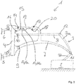
- Fig. 1 to 3 show a preferred embodiment of a designed as a mower, agricultural implement 1 for attachment to an agricultural towing vehicle, in particular for a front attachment or alternatively also for a rear attachment.
- the implement may be a mulcher, a snow blade, or a snow plow, or the like.
- the implement 1 has a working unit 2 which, when the implement 1 is designed as a mower, forms a mowing unit.
- the work unit 2 is attached to a support frame 3, wherein the support frame 3 has two articulated support frame sections 3a, 3b.
- the implement 1 further has a mounting frame 4, via which the implement 1 can be coupled to a hoist of an agricultural towing vehicle. From the hoist are in Fig. 1 a top link 6 and a lower link 5 are shown, which engage the mounting frame 4.
- the agricultural implement has in addition to the mounting frame 4 and support frame 3 via at least two links 7, 8.
- the links 7, 8 are connected to the support frame 3 and the mounting frame 4 to form a multi-joint kinematics, in the embodiment shown to form a four-joint kinematics.
- a first pivot axis 9 is formed between a first end of the link 7 and the mounting frame 4.
- Another pivot axis 10 is formed between the mounting frame 4 and a first end of the arm 8.
- Further pivot axes 11, 12 are formed between the second ends of the links 7, 8 and the support frame 3, wherein in the pivot axis 11 of the arm 7 engages both support frame sections 3a, 3b of the support frame 3 articulated.
- the agricultural attachment 1 further has a parking flap 13.
- the parking flap 13 engages with a first end articulated on the mounting frame 4 to form a pivot axis 14.
- the multi-joint kinematics can be blocked by means of the parking flap 13.
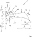
- the parking flap 13 is formed to extend from a blocking position (see FIG Fig. 3 ), in which the same blocks the multi-joint kinematics, automatically in a release position (see Fig. 1 ), in which it releases the multi-joint kinematics.
- the fixing lever 15 is as well as the parking flap 13 hinged at a first end to the mounting frame 4, to form a further pivot axis 16. An opposite second end of the fixing lever 15 is guided in a slotted guide of the parking flap 13.
- the slotted guide 17 has several sections. Then, when the second end of the fixing lever 15 engages in a first portion 17 a of the slotted guide 17 of the parking flap 13, the interaction of fixing lever 15 and parking flap 13 fixes the parking flap 13 in a fixing position (see Fig. 2 ).
- the first section 17a of the slide guide 17 forms a support groove or a projection on which the second end of the fixing lever 15 hooks, so that the parking flap 13 is supported in the fixing position on the fixing lever 15.
- a handlebar To the implement 1 or the multi-joint kinematics of the implement 1 in the park position (see Fig. 3 ) is on a handlebar, in the embodiment of Fig. 1 to 3 on the handlebar 7, namely on a projection 18 of the handlebar 7, a locking element 19 is formed, which can be brought into engagement with the second end of the parking flap 13.
- the parking door 13 in the in Fig. 2 transferred shown fixing position namely, when the implement 1 occupies the working position and is coupled to the handlebars 5, 6 of the hoist of the towing vehicle.
- the parking flap 13 is only starting from the in Fig. 1 shown release position in the in Fig. 2 transferred shown fixing position, in which case the second end of the fixing lever 15 enters the first section 17a of the guide slot 17 and so fixes the parking flap 13 in its fixing position.
- the parking flap 13 pivoted slightly upwards, so that then the second end of the fixing lever 15 automatically from the first Section 17a of the slotted guide out in the second section 17b of the slotted guide 17 is transferred into it.
- the second end of the fixing lever 15 is relieved in the - formed by the first portion 17a of the guide slot 17 - support notch and falls by its weight from the support notch out in the second section 17b the slide guide 17.
- the parking flap 13 is transferred from the fixing position to the blocking position.
- the transfer of the second end of the fixing lever 15 from the first portion 17 a to the second portion 17 b of the guide slot 17 may optionally be supported by a spring.
- the implement 1 is again coupled to a hoist of the towing vehicle and raised the mounting frame 4 on the hoist, the second end of the parking door 13 is disengaged from the locking element 19 and the parking flap 13 may due to the fact that the second end of the fixing lever 15 in the second section 17 b of the guide slot 17 is located automatically in the in Fig. 1 return to the released release position.
- the implement 1 according to the invention can be transferred from a parking position to a working position without manual access. For this purpose, no manual access to the parking door 13 is required. This can save working time.
- a handle is arranged on the fixing lever 15, with which an operator can shift the parking flap 13 into the fixing position.
- a notch or a projection can alternatively be provided, on which or the locking lever and the parking flap in the fixing position hook together.
Landscapes
- Life Sciences & Earth Sciences (AREA)
- Engineering & Computer Science (AREA)
- Mechanical Engineering (AREA)
- Soil Sciences (AREA)
- Environmental Sciences (AREA)
- Zoology (AREA)
- Agricultural Machines (AREA)
Abstract
Description
- Die Erfindung betrifft ein landwirtschaftliches Arbeitsgerät zum Anbau an ein landwirtschaftliches Zugfahrzeug.
- Aus der
DE 10 2014 101 232 A1 ist ein als Mähwerk ausgebildetes landwirtschaftliches Arbeitsgerät für einen Frontanbau an ein landwirtschaftliches Zugfahrzeug bekannt. Dieses Arbeitsgerät verfügt über einen Anbaurahmen, über welchen das Arbeitsgerät an ein Fronthubwerk eines landwirtschaftlichen Zugfahrzeugs ankoppelbar ist. Das Arbeitsgerät verfügt weiterhin über einen Tragrahmen, an welchem eine Arbeitseinheit, die als Mäheinheit ausgebildet ist, angreift. Anbaurahmen und Tragrahmen sind über Lenker unter Ausbildung einer Viergelenkkinematik miteinander gekoppelt. Zwischen den Enden der Lenker sowie dem Anbaurahmen und Tragrahmen sind dabei vier Schwenkachsen ausgebildet. - Das Arbeitsgerät der
DE 10 2014 101 232 A1 umfasst weiterhin eine Parkklappe, die am Anbaurahmen gelenkig gelagert ist. Die Parkklappe ist zwischen einer Freigabeposition und einer Fixierposition verlagerbar. Es besteht Bedarf an einem Arbeitsgerät mit verbesserter Handhabbarkeit der Parkklappe. - Diese Aufgabe wird durch ein landwirtschaftliches Arbeitsgerät nach Anspruch 1 gelöst.
- Erfindungsgemäß ist die Parkklappe derart ausgebildet, dass dieselbe aus einer Blockierposition, in welcher dieselbe die Mehrgelenkkinematik blockiert oder sperrt, selbsttätig in eine Freigabeposition, in welcher dieselbe die Mehrgelenkkinematik freigibt, zurückkehrt. Dann, wenn das landwirtschaftliche Arbeitsgerät aus einer Parkstellung heraus in eine Arbeitsstellung zu überführen ist, kann sich die Parkklappe selbsttätig aus ihrer Blockierposition in ihre Freigabeposition bewegen. Hierzu ist es nicht erforderlich, dass ein Fahrer des Zugfahrzeugs oder eine sonstige Person manuell auf die Parkklappe zugreift.
- Nach einer Weiterbildung sind die Parkklappe und ein mit der Parkklappe zusammenwirkender Fixierhebel jeweils mit einem ersten Ende am Anbaurahmen gelagert, wobei ein zweites Ende des Fixierhebels in einer Kulissenführung der Parkklappe geführt ist. Die Kulissenführung der Parkklappe weist mehrere Abschnitte auf, nämlich einen ersten Abschnitt, der im Zusammenspiel mit dem zweiten Ende des Fixierhebels die Parkklappe fixiert, und einen zweiten Abschnitt, der im Zusammenspiel mit dem zweiten Ende des Fixierhebels die Parkklappe freigibt. Diese Ausführung ist besonders einfach und robust. Das Zusammenspiel zwischen Fixierhebel und Parkklappe erlaubt einerseits eine einfache und zuverlässige Überführung der Parkklappe ausgehend von der Freigabeposition in eine Fixierposition und andererseits anders herum von der Fixierposition über die Blockierposition in die Freigabeposition.
- Nach einer Weiterbildung ist an einem Lenker ein Rastelement ausgebildet, welches mit einem zweiten Ende der Parkklappe in Eingriff bringbar ist. Vorzugsweise weist das Rastelement eine Einfahrschräge für das zweite Ende der Parkklappe auf. Diese Ausführung ist bevorzugt, um das selbsttätige Zurückkehren der Parkklappe in die Freigabeposition zu gewährleisten.
- Nach einer Weiterbildung ist das zweite Ende des Fixierhebels im zweiten Abschnitt der Kulissenführung der Parkklappe geführt, wenn bei Arbeitsgerät in Arbeitsstellung das Rastelement mit dem zweiten Ende der Parkklappe außer Eingriff ist, und die Parkklappe eine Freigabeposition einnimmt.
- Dann, wenn bei Arbeitsgerät in Arbeitsstellung das Rastelement mit dem zweiten Ende der Parkklappe außer Eingriff ist und die Parkklappe eine Fixierposition einnimmt, ist das zweite Ende des Fixierhebels im ersten Abschnitt der Kulissenführung der Parkklappe geführt.
- Dann, wenn bei Arbeitsgerät in Parkstellung das Rastelement mit dem zweiten Ende der Parkklappe in Eingriff ist und die Parkklappe die Blockierposition einnimmt, ist das zweite Ende des Fixierhebels im zweiten Abschnitt der Kulissenführung der Parkklappe geführt.
- Dann, wenn bei Überführung des Arbeitsgeräts von der Arbeitsstellung in die Parkstellung und bei Parkklappe in Fixierposition das zweite Ende der Parkklappe in Eingriff mit dem Rastelement gelangt, überführt vorzugsweise die Einfahrschräge des Rastelements das zweite Ende des Fixierhebels vom ersten Abschnitt der Kulissenführung der Parkklappe in den zweiten Abschnitt der Kulissenführung der Parkklappe und überführt so die Parkklappe von der Fixierposition in die Blockierposition. Diese Details erlauben ein besonders bevorzugtes Überführen des landwirtschaftlichen Arbeitsgeräts zwischen der Arbeitsstellung und der Parkstellung sowie eine besonders vorteilhafte Überführung der Parkklappe zwischen der Fixierposition über die Blockierposition in die Freigabeposition.
- Bevorzugte Weiterbildungen der Erfindung ergeben sich aus den Unteransprüchen und der nachfolgenden Beschreibung. Ausführungsbeispiele der Erfindung werden, ohne hierauf beschränkt zu sein, an Hand der Zeichnung näher erläutert. Dabei zeigen:
- Fig. 1
- eine schematische Darstellung eines erfindungsgemäßen Arbeitsgeräts in der Arbeitsstellung mit Parkklappe in der Freigabeposition;
- Fig. 2
- eine schematische Darstellung des erfindungsgemäßen Arbeitsgeräts der
Fig. 1 in der Arbeitsstellung mit Parkklappe in der Fixierposition; - Fig. 3
- eine schematische Darstellung des erfindungsgemäßen Arbeitsgeräts der
Fig. 1 ,2 in der Parkstellung mit Parkklappe in der Blockierposition. - Die Erfindung betrifft einen ein landwirtschaftliches Arbeitsgerät zum Anbau an ein landwirtschaftliches Zugfahrzeug.
-
Fig. 1 bis 3 zeigen ein bevorzugtes Ausführungsbeispiel eines als Mähwerk ausgebildeten, landwirtschaftlichen Arbeitsgeräts 1 für den Anbau an ein landwirtschaftliches Zugfahrzeug, insbesondere für einen Frontanbau oder alternativ auch für einen Heckanbau. Alternativ kann das Arbeitsgerät ein Mulchgerät, ein Räumschild oder ein Schneeschiebeschild o. ä. sein. - Das Arbeitsgerät 1 verfügt über eine Arbeitseinheit 2, die dann, wenn das Arbeitsgerät 1 als Mähwerk ausgebildet ist, eine Mäheinheit bildet. Die Arbeitseinheit 2 ist an einen Tragrahmen 3 befestigt, wobei der Tragrahmen 3 zwei gelenkig miteinander verbundene Tragrahmenabschnitte 3a, 3b aufweist.
- Das Arbeitsgerät 1 verfügt weiterhin über einen Anbaurahmen 4, über welchen das Arbeitsgerät 1 an ein Hubwerk eines landwirtschaftlichen Zugfahrzeugs ankoppelbar ist. Vom Hubwerk sind in
Fig. 1 ein Oberlenker 6 und ein Unterlenker 5 gezeigt, die an dem Anbaurahmen 4 angreifen. - Das landwirtschaftliche Arbeitsgerät verfügt zusätzlich zum Anbaurahmen 4 und Tragrahmen 3 über mindestens zwei Lenker 7, 8. Die Lenker 7, 8 sind mit dem Tragrahmen 3 und dem Anbaurahmen 4 unter Ausbildung einer Mehrgelenkkinematik, im gezeigten Ausführungsbeispiel unter Ausbildung einer Viergelenkkinematik, miteinander verbunden.
- So ist zwischen einem ersten Ende des Lenkers 7 und dem Anbaurahmen 4 eine erste Schwenkachse 9 ausgebildet. Eine weitere Schwenkachse 10 ist zwischen dem Anbaurahmen 4 und einem ersten Ende des Lenkers 8 ausgebildet. Weitere Schwenkachsen 11, 12 sind zwischen den zweiten Enden der Lenker 7, 8 und dem Tragrahmen 3 ausgebildet, wobei in der Schwenkachse 11 der Lenker 7 an beiden Tragrahmenabschnitten 3a, 3b des Tragrahmens 3 gelenkig angreift.
- Das landwirtschaftliche Anbaugerät 1 verfügt weiterhin über eine Parkklappe 13. Die Parkklappe 13 greift mit einem ersten Ende gelenkig am Anbaurahmen 4 unter Ausbildung einer Schwenkachse 14 an.
- Die Mehrgelenkkinematik ist mithilfe der Parkklappe 13 blockierbar.
- Die Parkklappe 13 ist derart ausgebildet, dass dieselbe aus einer Blockierposition (siehe
Fig. 3 ), in welcher die dieselbe die Mehrgelenkkinematik blockiert, selbsttätig in eine Freigabeposition (sieheFig. 1 ) zurückkehrt, in welcher dieselbe die Mehrgelenkkinematik freigibt. - Mit der Parkklappe 13 wirkt ein Fixierhebel 15 zusammen.
- Der Fixierhebel 15 ist ebenso wie die Parkklappe 13 mit einem ersten Ende gelenkig an dem Anbaurahmen 4 befestigt, und zwar unter Ausbildung einer weiteren Schwenkachse 16. Ein gegenüberliegendes zweites Ende des Fixierhebels 15 ist in einer Kulissenführung der Parkklappe 13 geführt.
- Die Kulissenführung 17 weist mehrere Abschnitte auf. Dann, wenn das zweite Ende des Fixierhebels 15 in einen ersten Abschnitt 17a der Kulissenführung 17 der Parkklappe 13 eingreift, fixiert das Zusammenspiel aus Fixierhebel 15 und Parkklappe 13 die Parkklappe 13 in einer Fixierposition (siehe
Fig. 2 ). Dabei bildet der erste Abschnitt 17a der Kulissenführung 17 eine Stützkerbe bzw. einen Vorsprung, an dem das zweite Ende des Fixierhebels 15 einhakt, so dass die Parkklappe 13 in der Fixierposition auf dem Fixierhebel 15 abgestützt ist. - Dann hingegen, wenn das zweite Ende des Fixierhebels 17 in einen zweiten Abschnitt 17b der Kulissenführung der Parkklappe 13 eingreift, gibt das Zusammenspiel aus Fixierhebel 15 und Parkklappe 13 die Parkklappe 13 frei (siehe
Fig. 1 ,3 ). - Um das Arbeitsgerät 1 bzw. die Mehrgelenkkinematik des Arbeitsgeräts 1 in der Parkstellung (siehe
Fig. 3 ) zu blockieren, ist an einem Lenker, im Ausführungsbeispiel derFig. 1 bis 3 am Lenker 7, nämlich an einem Vorsprung 18 des Lenkers 7, ein Rastelement 19 ausgebildet, welches mit dem zweiten Ende der Parkklappe 13 in Eingriff gebracht werden kann. - Dann, wenn, wie in
Fig. 1 gezeigt, das Arbeitsgerät 1 sich in der Arbeitsstellung befindet und an das Hubwerk des Zugfahrzeugs angekoppelt ist, ist das Rastelement 19 des Lenkers 7 außer Eingriff mit dem zweiten Ende der Parkklappe 13. Die Parkklappe 13 nimmt ihre Freigabeposition ein, und das zweite Ende des Fixierhebels 15 ist im zweiten Abschnitt 17b der Kulissenführung 17 der Parkklappe 3 geführt. - Soll das Arbeitsgerät, ausgehend von der Arbeitsstellung der
Fig. 1 in die Parkstellung derFig. 3 überführt werden, so wird zunächst die Parkklappe 13 in die inFig. 2 gezeigte Fixierposition überführt, nämlich dann, wenn das Arbeitsgerät 1 die Arbeitsstellung einnimmt und an die Lenker 5, 6 des Hubwerks des Zugfahrzeugs angekoppelt ist. Hierzu wird die Parkklappe 13 lediglich ausgehend von der inFig. 1 gezeigten Freigabeposition in die inFig. 2 gezeigte Fixierposition überführt, wobei hierbei das zweite Ende des Fixierhebels 15 in den ersten Abschnitt 17a der Kulissenführung 17 gelangt und so die Parkklappe 13 in ihrer Fixierposition fixiert. - Dann, wenn das Arbeitsgerät die Parkstellung gemäß
Fig. 3 einnimmt, steht das Rastelement 19 mit dem zweiten Ende der Parkklappe 13 in Eingriff, das zweite Ende des Fixierhebels 15 ist aus dem ersten Abschnitt 17a der Kulissenführung 17 heraus in den zweiten Abschnitt 17b der Kulissenführung 17 der Parkklappe 13 überführt. - Dann, wenn das Arbeitsgerät 1 aus dem Zustand der
Fig. 2 heraus in den Zustand derFig. 3 überführt wird, wenn also die Lenker 5, 6 des Hubwerks des landwirtschaftlichen Zugfahrzeugs vom Anbaurahmen 4 abgekoppelt werden und sich der Anbaurahmen 4 infolge der Schwerkraft nach unten bewegt, wird die Viergelenkkinematik verschwenkt. Hierbei gelangt das zweite Ende der in der Fixierposition durch den Fixierhebel 15 fixierten Parkklappe 13 automatisch in Eingriff mit dem Rastelement 19 des Lenkers 7. - Im Bereich des Rastelements 19 ist dabei eine Einfahrschräge 20 ausgebildet, die dann, wenn das zweite Ende der Parkklappe 13 in Eingriff mit dem Rastelement 19 gelangt, die Parkklappe 13 etwas nach oben verschwenkt, sodass dann das zweite Ende des Fixierhebels 15 automatisch aus dem ersten Abschnitt 17a der Kulissenführung heraus in den zweiten Abschnitt 17b der Kulissenführung 17 hinein überführt wird. Durch das Anheben der Parkklappe 13 beim Einlaufen in das Rastelement 19 wird das zweite Ende des Fixierhebels 15 in der - vom ersten Abschnitt 17a der Kulissenführung 17 gebildeten - Stützkerbe entlastet und fällt durch seine Gewichtskraft aus der Stützkerbe heraus in den zweiten Abschnitt 17b der Kulissenführung 17. Wenn das zweite Ende der Parkklappe 13 im Rastelement 19 eingerastet ist, dann ist die Parkklappe 13 von der Fixierposition in die Blockierposition überführt. Das Überführen des zweiten Endes des Fixierhebels 15 vom ersten Abschnitt 17a zum zweiten Abschnitt 17b der Kulissenführung 17 kann ggf. durch eine Feder unterstützt werden.
- Wird nachfolgend, ausgehend von der Parkstellung der
Fig. 3 das Arbeitsgerät 1 wieder an ein Hubwerk des Zugfahrzeugs angekoppelt und der Anbaurahmen 4 über das Hubwerk angehoben, gelangt das zweite Ende der Parkklappe 13 außer Eingriff mit dem Rastelement 19 und die Parkklappe 13 kann infolge des Umstands, dass das zweite Ende des Fixierhebels 15 sich im zweiten Abschnitt 17b der Kulissenführung 17 befindet, selbsttätig in die inFig. 1 gezeigte Freigabeposition zurückkehren. - Das erfindungsgemäße Arbeitsgerät 1 kann ohne manuellen Zugriff von einer Parkstellung in eine Arbeitsstellung überführt werden. Hierzu ist kein manueller Zugriff auf die Parkklappe 13 erforderlich. Dadurch kann Arbeitszeit eingespart werden.
- Vorzugsweise ist am Fixierhebel 15 ein Handgriff angeordnet, mit welchem ein Bediener die Parkklappe 13 in die Fixierposition verlagern kann.
- Statt der beispielhaften Kulissenführung kann alternativ eine Kerbe oder ein Vorsprung vorgesehen werden, an der bzw. dem sich der Fixierhebel und die Parkklappe in der Fixierposition miteinander verhaken.
-
- 1
- Arbeitsgerät
- 2
- Arbeitseinheit
- 3
- Tragrahmen
- 3a
- Tragrahmenabschnitt
- 3b
- Tragrahmenabschnitt
- 4
- Anbaurahmen
- 5
- Unterlenker
- 6
- Oberlenker
- 7
- Lenker
- 8
- Lenker
- 9
- Schwenkachse
- 10
- Schwenkachse
- 11
- Schwenkachse
- 12
- Schwenkachse
- 13
- Parkklappe
- 14
- Schwenkachse
- 15
- Fixierhebel
- 16
- Schwenkachse
- 17
- Kulissenführung
- 17a
- Abschnitt
- 17b
- Abschnitt
- 18
- Vorsprung
- 19
- Rastelement
- 20
- Einfahrschräge
Claims (10)
- Landwirtschaftliches Arbeitsgerät (1) zum Anbau an ein landwirtschaftliches Zugfahrzeug,
mit einem Anbaurahmen (4), über welchen das Arbeitsgerät an ein Hubwerk des Zugfahrzeugs ankoppelbar ist,
mit einem Tragrahmen (3), an welchem eine Arbeitseinheit (2) angreift,
wobei der Anbaurahmen (4) und der Tragrahmen (3) über mindestens zwei Lenker (7, 8) unter Ausbildung einer Mehrgelenkkinematik miteinander verbunden sind,
mit einer Parkklappe (13), welche am Anbaurahmen (4) gelenkig gelagert ist und über welche die Mehrgelenkkinematik blockierbar ist,
dadurch gekennzeichnet, dass
die Parkklappe (13) derart ausgebildet ist, dass dieselbe aus einer Blockierposition, in welcher dieselbe die Mehrgelenkkinematik blockiert, selbsttätig in eine Freigabeposition, in welcher dieselbe die Mehrgelenkkinematik freigibt, zurückkehrt. - Arbeitsgerät nach Anspruch 1, dadurch gekennzeichnet, dass die Parkklappe (13) und ein mit der Parkklappe (13) zusammenwirkender Fixierhebel (15) jeweils mit einem ersten Ende am Anbaurahmen (4) gelenkig gelagert sind, wobei ein zweites Ende des Fixierhebels (15) in einer Kulissenführung (17) der Parkklappe (13) geführt ist.
- Arbeitsgerät nach Anspruch 2, dadurch gekennzeichnet, dass die Kulissenführung (17) der Parkklappe (13) mehrere Abschnitte aufweist, nämlich
einen ersten Abschnitt (17a), der im Zusammenspiel mit dem zweiten Ende des Fixierhebels (15) die Parkklappe (13) in einer Fixierposition fixiert,
einen zweiten Abschnitt (17b), der im Zusammenspiel mit dem zweiten Ende des Fixierhebels (15) die Parkklappe (13) freigibt. - Arbeitsgerät nach Anspruch 2 oder 3, dadurch gekennzeichnet, dass an einem Lenker (7) ein Rastelement (19) ausgebildet ist, welches mit einem zweiten Ende der Parkklappe (13) in Eingriff bringbar ist.
- Arbeitsgerät nach Anspruch 4, dadurch gekennzeichnet, dass das Rastelement (19) eine Einfahrschräge (20) für das zweite Ende der Parkklappe (13) aufweist.
- Arbeitsgerät nach Anspruch 4 oder 5, dadurch gekennzeichnet, dass
dann, wenn bei Arbeitsgerät (1) in Arbeitsstellung das Rastelement (19) mit dem zweiten Ende der Parkklappe (13) außer Eingriff ist und die Parkklappe (13) die Freigabeposition einnimmt, das zweite Ende des Fixierhebels (15) im zweiten Abschnitt (17b) der Kulissenführung (17) der Parkklappe (13) geführt ist,
dann, wenn bei Arbeitsgerät (13) in Arbeitsstellung das Rastelement (19) mit dem zweiten Ende der Parkklappe (13) außer Eingriff ist und die Parkklappe (13) die Fixierposition einnimmt, das zweite Ende des Fixierhebels (15) im ersten Abschnitt (17a) der Kulissenführung (17) der Parkklappe (13) geführt ist,
dann, wenn bei Arbeitsgerät (1) in Parkstellung das Rastelement (19) mit den zweiten Ende der Parkklappe (13) in Eingriff ist und die Parkklappe (13) die Blockierposition einnimmt, das zweite Ende des Fixierhebels (15) im zweiten Abschnitt (17b) der Kulissenführung (17) der Parkklappe (13) geführt ist. - Arbeitsgerät nach Anspruch 6, dadurch gekennzeichnet, dass dann, wenn bei Überführung des Arbeitsgeräts (1) von der Arbeitsstellung in die Parkstellung und bei Parkklappe (13) in Fixierposition das zweite Ende der Parkklappe (13) in Eingriff mit dem Rastelement (19) gelangt, die Einfahrschräge (20) die Parkklappe (13) von der Fixierposition in die Blockierposition überführt.
- Arbeitsgerät nach Anspruch 7, dadurch gekennzeichnet, dass hierbei die Einfahrschräge (20) des Rastelements (19) das zweite Ende des Fixierhebels (15) vom ersten Abschnitt (17a) der Kulissenführung (17) der Parkklappe (13) in den zweiten Abschnitt (17b) der Kulissenführung (17) der Parkklappe (13) überführt.
- Arbeitsgerät nach einem der Ansprüche 1 bis 8, dadurch gekennzeichnet, dass dasselbe dem Frontanbau an das Zugfahrzeug dient.
- Arbeitsgerät nach einem der Ansprüche 1 bis 9, dadurch gekennzeichnet, dass dasselbe ein Mähwerk, ein Mulchgerät, ein Räumschild oder ein Schneeschiebeschild ist.
Priority Applications (2)
| Application Number | Priority Date | Filing Date | Title |
|---|---|---|---|
| PL18174114T PL3409087T3 (pl) | 2017-06-01 | 2018-05-24 | Rolnicze urządzenie robocze do montażu na ciągniku rolniczym |
| SI201830162T SI3409087T1 (sl) | 2017-06-01 | 2018-05-24 | Kmetijska delovna naprava za priključitev na kmetijsko vlečno vozilo |
Applications Claiming Priority (1)
| Application Number | Priority Date | Filing Date | Title |
|---|---|---|---|
| DE102017112066.1A DE102017112066A1 (de) | 2017-06-01 | 2017-06-01 | Landwirtschaftliches Arbeitsgerät zum Anbau an ein landwirtschaftliches Zugfahrzeug |
Publications (2)
| Publication Number | Publication Date |
|---|---|
| EP3409087A1 true EP3409087A1 (de) | 2018-12-05 |
| EP3409087B1 EP3409087B1 (de) | 2020-10-14 |
Family
ID=62386021
Family Applications (1)
| Application Number | Title | Priority Date | Filing Date |
|---|---|---|---|
| EP18174114.1A Active EP3409087B1 (de) | 2017-06-01 | 2018-05-24 | Landwirtschaftliches arbeitsgerät zum anbau an ein landwirtschaftliches zugfahrzeug |
Country Status (4)
| Country | Link |
|---|---|
| EP (1) | EP3409087B1 (de) |
| DE (1) | DE102017112066A1 (de) |
| PL (1) | PL3409087T3 (de) |
| SI (1) | SI3409087T1 (de) |
Families Citing this family (1)
| Publication number | Priority date | Publication date | Assignee | Title |
|---|---|---|---|---|
| PL249106B1 (pl) * | 2023-09-01 | 2026-03-02 | Samasz Spolka Z Ograniczona Odpowiedzialnoscia | Stopa podporowa kosiarki czołowej i sposób jej sterowania |
Citations (4)
| Publication number | Priority date | Publication date | Assignee | Title |
|---|---|---|---|---|
| DE19624396A1 (de) * | 1996-06-19 | 1998-01-15 | Hans Grenzebach | Mähwerk, insbesondere für den Frontanbau |
| US20080127622A1 (en) * | 2005-01-26 | 2008-06-05 | Kuhn S.A. | Lawn Mower Provided With an Improved Folding and Unfolding Device |
| DE202005021554U1 (de) * | 2005-12-23 | 2008-11-20 | Claas Saulgau Gmbh | Mähmaschine |
| DE102014101232A1 (de) * | 2014-01-31 | 2015-08-06 | Claas Saulgau Gmbh | Mähwerk für einen Frontanbau an ein landwirtschaftliches Zugfahrzeug |
-
2017
- 2017-06-01 DE DE102017112066.1A patent/DE102017112066A1/de not_active Withdrawn
-
2018
- 2018-05-24 EP EP18174114.1A patent/EP3409087B1/de active Active
- 2018-05-24 PL PL18174114T patent/PL3409087T3/pl unknown
- 2018-05-24 SI SI201830162T patent/SI3409087T1/sl unknown
Patent Citations (4)
| Publication number | Priority date | Publication date | Assignee | Title |
|---|---|---|---|---|
| DE19624396A1 (de) * | 1996-06-19 | 1998-01-15 | Hans Grenzebach | Mähwerk, insbesondere für den Frontanbau |
| US20080127622A1 (en) * | 2005-01-26 | 2008-06-05 | Kuhn S.A. | Lawn Mower Provided With an Improved Folding and Unfolding Device |
| DE202005021554U1 (de) * | 2005-12-23 | 2008-11-20 | Claas Saulgau Gmbh | Mähmaschine |
| DE102014101232A1 (de) * | 2014-01-31 | 2015-08-06 | Claas Saulgau Gmbh | Mähwerk für einen Frontanbau an ein landwirtschaftliches Zugfahrzeug |
Also Published As
| Publication number | Publication date |
|---|---|
| EP3409087B1 (de) | 2020-10-14 |
| PL3409087T3 (pl) | 2021-03-08 |
| DE102017112066A1 (de) | 2018-12-06 |
| SI3409087T1 (sl) | 2021-01-29 |
Similar Documents
| Publication | Publication Date | Title |
|---|---|---|
| EP1656046B1 (de) | An einem träger verschwenkbar angeordneter ausleger für einen freiarmschirm | |
| DE4118683C1 (de) | ||
| DE102008033431B4 (de) | Anschlagelement für eine Sicherungseinrichtung | |
| EP0695655B1 (de) | Zugvorrichtung und Verriegelungsvorrichtung | |
| DE1247725B (de) | Schnellkupplung | |
| DE69211610T2 (de) | Mähmaschine mit schwenkbarer Kupplungsstruktur | |
| EP0792574A1 (de) | Gezogenes Gerät | |
| DE69706332T2 (de) | Mähmaschine | |
| EP1522429B1 (de) | Kupplungshaken | |
| DE2638904C2 (de) | Oberlenker einer Dreipunktanbauvorrichtung zum Anbau von Arbeitsgeräten an einen Ackerschlepper | |
| EP3409087A1 (de) | Landwirtschaftliches arbeitsgerät zum anbau an ein landwirtschaftliches zugfahrzeug | |
| DE2810903C3 (de) | Überlastsicherung für einen Pflug | |
| EP1961284B1 (de) | Anordnung zur Befestigung eines Oberlenkers einer Dreipunktanbaueinrichtung für landwirtschaftliche Nutzfahrzeuge in einer Außerbetriebsstellung | |
| DE8715674U1 (de) | Heuwerbungsmaschine | |
| EP3517685B1 (de) | Anbauteil für eine bodenreinigungsmaschine | |
| DE2949335A1 (de) | Selbsttaetige aushebeeinrichtung fuer ein landwirtschaftliches geraet, insbesondere ein maehwerk | |
| DE2456971C2 (de) | Kupplungshaken, insbesondere für ein Dreipunktgestänge eines Schleppers | |
| DE69917571T2 (de) | Heuwerbungsmaschine | |
| DE602005004358T2 (de) | Maschine mit einer Anschlußvorrichtung am Dreipunkt Kupplungssystem eines Traktors | |
| DE2440656C2 (de) | Ladewagen mit Heckklappe | |
| DE2312380C3 (de) | Dreipunktanbauvorrichtung, insbesondere für einen Schlepper | |
| DE2308218C3 (de) | Vorrichtung zum Kuppeln eines Fahrzeuges, insbesondere eines bau- oder landwirtschaftlichen Schleoppers mit einem Gerät, Anhänger od.dgl. und/oder Anhängern miteinander | |
| DE1555196C (de) | Kupplungsvorrichtung zum Anschhes sen eines Anhangers insbesondere eines Einachsanhangers, an ein Zugfahrzeug | |
| DE202023002839U1 (de) | Schließbare Lastengreifeinrichtung mit schwenkbaren Greifklinken | |
| DE7437516U (de) | Geraet zur entnahme von futterportionen |
Legal Events
| Date | Code | Title | Description |
|---|---|---|---|
| PUAI | Public reference made under article 153(3) epc to a published international application that has entered the european phase |
Free format text: ORIGINAL CODE: 0009012 |
|
| STAA | Information on the status of an ep patent application or granted ep patent |
Free format text: STATUS: THE APPLICATION HAS BEEN PUBLISHED |
|
| AK | Designated contracting states |
Kind code of ref document: A1 Designated state(s): AL AT BE BG CH CY CZ DE DK EE ES FI FR GB GR HR HU IE IS IT LI LT LU LV MC MK MT NL NO PL PT RO RS SE SI SK SM TR |
|
| AX | Request for extension of the european patent |
Extension state: BA ME |
|
| STAA | Information on the status of an ep patent application or granted ep patent |
Free format text: STATUS: REQUEST FOR EXAMINATION WAS MADE |
|
| 17P | Request for examination filed |
Effective date: 20190605 |
|
| RBV | Designated contracting states (corrected) |
Designated state(s): AL AT BE BG CH CY CZ DE DK EE ES FI FR GB GR HR HU IE IS IT LI LT LU LV MC MK MT NL NO PL PT RO RS SE SI SK SM TR |
|
| RIC1 | Information provided on ipc code assigned before grant |
Ipc: A01B 59/04 20060101ALI20200430BHEP Ipc: A01D 34/64 20060101ALI20200430BHEP Ipc: A01B 63/108 20060101AFI20200430BHEP Ipc: A01D 34/66 20060101ALN20200430BHEP |
|
| RIC1 | Information provided on ipc code assigned before grant |
Ipc: A01B 63/108 20060101AFI20200519BHEP Ipc: A01D 34/64 20060101ALI20200519BHEP Ipc: A01B 59/04 20060101ALI20200519BHEP Ipc: A01D 34/66 20060101ALN20200519BHEP |
|
| GRAP | Despatch of communication of intention to grant a patent |
Free format text: ORIGINAL CODE: EPIDOSNIGR1 |
|
| STAA | Information on the status of an ep patent application or granted ep patent |
Free format text: STATUS: GRANT OF PATENT IS INTENDED |
|
| INTG | Intention to grant announced |
Effective date: 20200629 |
|
| GRAS | Grant fee paid |
Free format text: ORIGINAL CODE: EPIDOSNIGR3 |
|
| GRAA | (expected) grant |
Free format text: ORIGINAL CODE: 0009210 |
|
| STAA | Information on the status of an ep patent application or granted ep patent |
Free format text: STATUS: THE PATENT HAS BEEN GRANTED |
|
| AK | Designated contracting states |
Kind code of ref document: B1 Designated state(s): AL AT BE BG CH CY CZ DE DK EE ES FI FR GB GR HR HU IE IS IT LI LT LU LV MC MK MT NL NO PL PT RO RS SE SI SK SM TR |
|
| REG | Reference to a national code |
Ref country code: GB Ref legal event code: FG4D Free format text: NOT ENGLISH |
|
| REG | Reference to a national code |
Ref country code: AT Ref legal event code: REF Ref document number: 1322627 Country of ref document: AT Kind code of ref document: T Effective date: 20201015 Ref country code: CH Ref legal event code: EP |
|
| REG | Reference to a national code |
Ref country code: DE Ref legal event code: R096 Ref document number: 502018002714 Country of ref document: DE |
|
| REG | Reference to a national code |
Ref country code: IE Ref legal event code: FG4D Free format text: LANGUAGE OF EP DOCUMENT: GERMAN |
|
| REG | Reference to a national code |
Ref country code: NL Ref legal event code: MP Effective date: 20201014 |
|
| PG25 | Lapsed in a contracting state [announced via postgrant information from national office to epo] |
Ref country code: GR Free format text: LAPSE BECAUSE OF FAILURE TO SUBMIT A TRANSLATION OF THE DESCRIPTION OR TO PAY THE FEE WITHIN THE PRESCRIBED TIME-LIMIT Effective date: 20210115 Ref country code: NO Free format text: LAPSE BECAUSE OF FAILURE TO SUBMIT A TRANSLATION OF THE DESCRIPTION OR TO PAY THE FEE WITHIN THE PRESCRIBED TIME-LIMIT Effective date: 20210114 Ref country code: RS Free format text: LAPSE BECAUSE OF FAILURE TO SUBMIT A TRANSLATION OF THE DESCRIPTION OR TO PAY THE FEE WITHIN THE PRESCRIBED TIME-LIMIT Effective date: 20201014 Ref country code: PT Free format text: LAPSE BECAUSE OF FAILURE TO SUBMIT A TRANSLATION OF THE DESCRIPTION OR TO PAY THE FEE WITHIN THE PRESCRIBED TIME-LIMIT Effective date: 20210215 Ref country code: FI Free format text: LAPSE BECAUSE OF FAILURE TO SUBMIT A TRANSLATION OF THE DESCRIPTION OR TO PAY THE FEE WITHIN THE PRESCRIBED TIME-LIMIT Effective date: 20201014 |
|
| REG | Reference to a national code |
Ref country code: LT Ref legal event code: MG4D |
|
| PG25 | Lapsed in a contracting state [announced via postgrant information from national office to epo] |
Ref country code: SE Free format text: LAPSE BECAUSE OF FAILURE TO SUBMIT A TRANSLATION OF THE DESCRIPTION OR TO PAY THE FEE WITHIN THE PRESCRIBED TIME-LIMIT Effective date: 20201014 Ref country code: IS Free format text: LAPSE BECAUSE OF FAILURE TO SUBMIT A TRANSLATION OF THE DESCRIPTION OR TO PAY THE FEE WITHIN THE PRESCRIBED TIME-LIMIT Effective date: 20210214 Ref country code: LV Free format text: LAPSE BECAUSE OF FAILURE TO SUBMIT A TRANSLATION OF THE DESCRIPTION OR TO PAY THE FEE WITHIN THE PRESCRIBED TIME-LIMIT Effective date: 20201014 Ref country code: BG Free format text: LAPSE BECAUSE OF FAILURE TO SUBMIT A TRANSLATION OF THE DESCRIPTION OR TO PAY THE FEE WITHIN THE PRESCRIBED TIME-LIMIT Effective date: 20210114 Ref country code: ES Free format text: LAPSE BECAUSE OF FAILURE TO SUBMIT A TRANSLATION OF THE DESCRIPTION OR TO PAY THE FEE WITHIN THE PRESCRIBED TIME-LIMIT Effective date: 20201014 |
|
| PG25 | Lapsed in a contracting state [announced via postgrant information from national office to epo] |
Ref country code: NL Free format text: LAPSE BECAUSE OF FAILURE TO SUBMIT A TRANSLATION OF THE DESCRIPTION OR TO PAY THE FEE WITHIN THE PRESCRIBED TIME-LIMIT Effective date: 20201014 Ref country code: HR Free format text: LAPSE BECAUSE OF FAILURE TO SUBMIT A TRANSLATION OF THE DESCRIPTION OR TO PAY THE FEE WITHIN THE PRESCRIBED TIME-LIMIT Effective date: 20201014 |
|
| REG | Reference to a national code |
Ref country code: DE Ref legal event code: R097 Ref document number: 502018002714 Country of ref document: DE |
|
| PG25 | Lapsed in a contracting state [announced via postgrant information from national office to epo] |
Ref country code: CZ Free format text: LAPSE BECAUSE OF FAILURE TO SUBMIT A TRANSLATION OF THE DESCRIPTION OR TO PAY THE FEE WITHIN THE PRESCRIBED TIME-LIMIT Effective date: 20201014 Ref country code: EE Free format text: LAPSE BECAUSE OF FAILURE TO SUBMIT A TRANSLATION OF THE DESCRIPTION OR TO PAY THE FEE WITHIN THE PRESCRIBED TIME-LIMIT Effective date: 20201014 Ref country code: SM Free format text: LAPSE BECAUSE OF FAILURE TO SUBMIT A TRANSLATION OF THE DESCRIPTION OR TO PAY THE FEE WITHIN THE PRESCRIBED TIME-LIMIT Effective date: 20201014 Ref country code: RO Free format text: LAPSE BECAUSE OF FAILURE TO SUBMIT A TRANSLATION OF THE DESCRIPTION OR TO PAY THE FEE WITHIN THE PRESCRIBED TIME-LIMIT Effective date: 20201014 Ref country code: SK Free format text: LAPSE BECAUSE OF FAILURE TO SUBMIT A TRANSLATION OF THE DESCRIPTION OR TO PAY THE FEE WITHIN THE PRESCRIBED TIME-LIMIT Effective date: 20201014 Ref country code: LT Free format text: LAPSE BECAUSE OF FAILURE TO SUBMIT A TRANSLATION OF THE DESCRIPTION OR TO PAY THE FEE WITHIN THE PRESCRIBED TIME-LIMIT Effective date: 20201014 |
|
| PLBE | No opposition filed within time limit |
Free format text: ORIGINAL CODE: 0009261 |
|
| STAA | Information on the status of an ep patent application or granted ep patent |
Free format text: STATUS: NO OPPOSITION FILED WITHIN TIME LIMIT |
|
| PG25 | Lapsed in a contracting state [announced via postgrant information from national office to epo] |
Ref country code: DK Free format text: LAPSE BECAUSE OF FAILURE TO SUBMIT A TRANSLATION OF THE DESCRIPTION OR TO PAY THE FEE WITHIN THE PRESCRIBED TIME-LIMIT Effective date: 20201014 |
|
| 26N | No opposition filed |
Effective date: 20210715 |
|
| PG25 | Lapsed in a contracting state [announced via postgrant information from national office to epo] |
Ref country code: AL Free format text: LAPSE BECAUSE OF FAILURE TO SUBMIT A TRANSLATION OF THE DESCRIPTION OR TO PAY THE FEE WITHIN THE PRESCRIBED TIME-LIMIT Effective date: 20201014 Ref country code: IT Free format text: LAPSE BECAUSE OF FAILURE TO SUBMIT A TRANSLATION OF THE DESCRIPTION OR TO PAY THE FEE WITHIN THE PRESCRIBED TIME-LIMIT Effective date: 20201014 |
|
| REG | Reference to a national code |
Ref country code: CH Ref legal event code: PL |
|
| PG25 | Lapsed in a contracting state [announced via postgrant information from national office to epo] |
Ref country code: CH Free format text: LAPSE BECAUSE OF NON-PAYMENT OF DUE FEES Effective date: 20210531 Ref country code: LI Free format text: LAPSE BECAUSE OF NON-PAYMENT OF DUE FEES Effective date: 20210531 Ref country code: MC Free format text: LAPSE BECAUSE OF FAILURE TO SUBMIT A TRANSLATION OF THE DESCRIPTION OR TO PAY THE FEE WITHIN THE PRESCRIBED TIME-LIMIT Effective date: 20201014 Ref country code: LU Free format text: LAPSE BECAUSE OF NON-PAYMENT OF DUE FEES Effective date: 20210524 |
|
| REG | Reference to a national code |
Ref country code: BE Ref legal event code: MM Effective date: 20210531 |
|
| PG25 | Lapsed in a contracting state [announced via postgrant information from national office to epo] |
Ref country code: BE Free format text: LAPSE BECAUSE OF NON-PAYMENT OF DUE FEES Effective date: 20210531 |
|
| GBPC | Gb: european patent ceased through non-payment of renewal fee |
Effective date: 20220524 |
|
| PG25 | Lapsed in a contracting state [announced via postgrant information from national office to epo] |
Ref country code: GB Free format text: LAPSE BECAUSE OF NON-PAYMENT OF DUE FEES Effective date: 20220524 |
|
| P01 | Opt-out of the competence of the unified patent court (upc) registered |
Effective date: 20230508 |
|
| PG25 | Lapsed in a contracting state [announced via postgrant information from national office to epo] |
Ref country code: CY Free format text: LAPSE BECAUSE OF FAILURE TO SUBMIT A TRANSLATION OF THE DESCRIPTION OR TO PAY THE FEE WITHIN THE PRESCRIBED TIME-LIMIT Effective date: 20201014 |
|
| PG25 | Lapsed in a contracting state [announced via postgrant information from national office to epo] |
Ref country code: HU Free format text: LAPSE BECAUSE OF FAILURE TO SUBMIT A TRANSLATION OF THE DESCRIPTION OR TO PAY THE FEE WITHIN THE PRESCRIBED TIME-LIMIT; INVALID AB INITIO Effective date: 20180524 |
|
| PG25 | Lapsed in a contracting state [announced via postgrant information from national office to epo] |
Ref country code: MK Free format text: LAPSE BECAUSE OF FAILURE TO SUBMIT A TRANSLATION OF THE DESCRIPTION OR TO PAY THE FEE WITHIN THE PRESCRIBED TIME-LIMIT Effective date: 20201014 |
|
| PG25 | Lapsed in a contracting state [announced via postgrant information from national office to epo] |
Ref country code: TR Free format text: LAPSE BECAUSE OF FAILURE TO SUBMIT A TRANSLATION OF THE DESCRIPTION OR TO PAY THE FEE WITHIN THE PRESCRIBED TIME-LIMIT Effective date: 20201014 |
|
| PG25 | Lapsed in a contracting state [announced via postgrant information from national office to epo] |
Ref country code: MT Free format text: LAPSE BECAUSE OF FAILURE TO SUBMIT A TRANSLATION OF THE DESCRIPTION OR TO PAY THE FEE WITHIN THE PRESCRIBED TIME-LIMIT Effective date: 20201014 |
|
| PGFP | Annual fee paid to national office [announced via postgrant information from national office to epo] |
Ref country code: PL Payment date: 20250516 Year of fee payment: 8 Ref country code: DE Payment date: 20250521 Year of fee payment: 8 |
|
| PGFP | Annual fee paid to national office [announced via postgrant information from national office to epo] |
Ref country code: FR Payment date: 20250528 Year of fee payment: 8 |
|
| PGFP | Annual fee paid to national office [announced via postgrant information from national office to epo] |
Ref country code: AT Payment date: 20250522 Year of fee payment: 8 |
|
| PGFP | Annual fee paid to national office [announced via postgrant information from national office to epo] |
Ref country code: IE Payment date: 20250521 Year of fee payment: 8 |
|
| PGFP | Annual fee paid to national office [announced via postgrant information from national office to epo] |
Ref country code: SI Payment date: 20250515 Year of fee payment: 8 |