EP3409087B1 - Landwirtschaftliches arbeitsgerät zum anbau an ein landwirtschaftliches zugfahrzeug - Google Patents
Landwirtschaftliches arbeitsgerät zum anbau an ein landwirtschaftliches zugfahrzeug Download PDFInfo
- Publication number
- EP3409087B1 EP3409087B1 EP18174114.1A EP18174114A EP3409087B1 EP 3409087 B1 EP3409087 B1 EP 3409087B1 EP 18174114 A EP18174114 A EP 18174114A EP 3409087 B1 EP3409087 B1 EP 3409087B1
- Authority
- EP
- European Patent Office
- Prior art keywords
- parking
- flap
- parking flap
- working implement
- working
- Prior art date
- Legal status (The legal status is an assumption and is not a legal conclusion. Google has not performed a legal analysis and makes no representation as to the accuracy of the status listed.)
- Active
Links
Images


Classifications
-
- A—HUMAN NECESSITIES
- A01—AGRICULTURE; FORESTRY; ANIMAL HUSBANDRY; HUNTING; TRAPPING; FISHING
- A01B—SOIL WORKING IN AGRICULTURE OR FORESTRY; PARTS, DETAILS, OR ACCESSORIES OF AGRICULTURAL MACHINES OR IMPLEMENTS, IN GENERAL
- A01B59/00—Devices specially adapted for connection between animals or tractors and agricultural machines or implements
- A01B59/04—Devices specially adapted for connection between animals or tractors and agricultural machines or implements for machines pulled or pushed by a tractor
-
- A—HUMAN NECESSITIES
- A01—AGRICULTURE; FORESTRY; ANIMAL HUSBANDRY; HUNTING; TRAPPING; FISHING
- A01B—SOIL WORKING IN AGRICULTURE OR FORESTRY; PARTS, DETAILS, OR ACCESSORIES OF AGRICULTURAL MACHINES OR IMPLEMENTS, IN GENERAL
- A01B63/00—Lifting or adjusting devices or arrangements for agricultural machines or implements
- A01B63/02—Lifting or adjusting devices or arrangements for agricultural machines or implements for implements mounted on tractors
- A01B63/10—Lifting or adjusting devices or arrangements for agricultural machines or implements for implements mounted on tractors operated by hydraulic or pneumatic means
- A01B63/102—Lifting or adjusting devices or arrangements for agricultural machines or implements for implements mounted on tractors operated by hydraulic or pneumatic means characterised by the location of the mounting on the tractor, e.g. on the rear part
- A01B63/108—Lifting or adjusting devices or arrangements for agricultural machines or implements for implements mounted on tractors operated by hydraulic or pneumatic means characterised by the location of the mounting on the tractor, e.g. on the rear part on the front part
-
- A—HUMAN NECESSITIES
- A01—AGRICULTURE; FORESTRY; ANIMAL HUSBANDRY; HUNTING; TRAPPING; FISHING
- A01D—HARVESTING; MOWING
- A01D34/00—Mowers; Mowing apparatus of harvesters
- A01D34/01—Mowers; Mowing apparatus of harvesters characterised by features relating to the type of cutting apparatus
- A01D34/412—Mowers; Mowing apparatus of harvesters characterised by features relating to the type of cutting apparatus having rotating cutters
- A01D34/63—Mowers; Mowing apparatus of harvesters characterised by features relating to the type of cutting apparatus having rotating cutters having cutters rotating about a vertical axis
- A01D34/64—Mowers; Mowing apparatus of harvesters characterised by features relating to the type of cutting apparatus having rotating cutters having cutters rotating about a vertical axis mounted on a vehicle, e.g. a tractor, or drawn by an animal or a vehicle
- A01D34/66—Mowers; Mowing apparatus of harvesters characterised by features relating to the type of cutting apparatus having rotating cutters having cutters rotating about a vertical axis mounted on a vehicle, e.g. a tractor, or drawn by an animal or a vehicle with two or more cutters
- A01D34/661—Mounting means
Definitions
- the invention relates to an agricultural implement for attachment to an agricultural tractor.
- US2008 / 0127622 A1 discloses a mower with a support structure that can be coupled to a tractor and carries a support beam to which a cutter bar is articulated, which can be displaced by means of a folding device from a working position into at least one transport position and vice versa, the folding device having a tilting element that is connected to the Support beam and the support structure is connected, a connecting rod connected to the cutter bar and a double-acting cylinder which is arranged between the tilting element and the connecting rod, comprises.
- a mower that can be attached to a tractor, especially for front mounting is known with a coupling frame that can be connected to the lifting device of the tractor and a support frame that accommodates the mowing elements, the support frame being arranged over several rods, two of which are arranged in the lower area and at least one in the upper area are, can be pivoted approximately parallelogram-like in a vertical plane with respect to the coupling frame and this pivotability is limited to an angular range, the arrangement and design of the rods deviating from an exact parallelogram arrangement being such that firstly the instantaneous pole as the intersection of the extension lines of the rods in the middle working position of the mower is below the horizontal floor surface and that, secondly, the angle of incidence of the mowing elements decreases when the support frame is pivoted upwards in a vertical plane.
- U1 discloses a mowing machine, in particular a side mower for attachment to a lifting device of an agricultural carrier vehicle, with a mowing device which is guided in a working and operating position to the side of the agricultural carrier vehicle and which comprises a number of cutting members rotating about a vertical axis, with a carrying and Guide device as a connecting link between Mower and carrier vehicle with a pivotable extension arm for folding the mowing device from an approximately horizontal working and operating position into a raised headland and / or transport position, the extension arm of the support device being in two parts and comprising a first extension element and a second extension element, the first Cantilever element designed as an angle lever which is the link between the supporting structure and the second boom element.
- This work device has a mounting frame, via which the work device can be coupled to a front lifting mechanism of an agricultural tractor.
- the work device also has a support frame on which a work unit, which is designed as a mower unit, engages.
- the mounting frame and the support frame are coupled to one another via links with the formation of four-bar kinematics. Four pivot axes are formed between the ends of the links and the mounting frame and support frame.
- the working device of the DE 10 2014 101 232 A1 further comprises a parking flap which is articulated on the mounting frame.
- the parking flap can be moved between a release position and a fixing position. There is a need for an implement with improved manageability of the parking flap.
- the parking flap is designed such that it automatically returns from a blocking position in which it blocks or blocks the multi-joint kinematics into a release position in which it releases the multi-joint kinematics. Then, when the agricultural implement is to be transferred from a parking position into a working position, the parking flap can move automatically from its blocking position into its release position. For this it is not necessary for a driver of the towing vehicle or another person to manually access the parking flap.
- the parking flap and a fixing lever interacting with the parking flap are each mounted with a first end on the mounting frame, a second end of the fixing lever being guided in a link guide of the parking flap.
- the link guide of the parking flap has several sections, namely a first section that fixes the parking flap in conjunction with the second end of the fixing lever, and a second section that releases the parking flap in conjunction with the second end of the fixing lever.
- a latching element is formed on a handlebar which can be brought into engagement with a second end of the parking flap.
- the latching element preferably has a bevel for the second end of the parking flap. This embodiment is preferred in order to ensure the automatic return of the parking flap to the release position.
- the second end of the fixing lever is guided in the second section of the link guide of the parking flap when the locking element is out of engagement with the second end of the parking flap when the implement is in the working position and the parking flap is in a release position.
- the latching element When, with the implement in the working position, the latching element is out of engagement with the second end of the parking flap and the parking flap assumes a fixing position, the second end of the fixing lever is guided in the first section of the link guide of the parking flap.
- the bevel of the locking element preferably transfers the second end of the fixing lever from the first section of the link guide of the parking flap to the second section of the link guide of the parking flap and thus transfers the parking flap from the fixing position to the blocking position.
- the invention relates to an agricultural implement for attachment to an agricultural tractor.
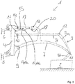
- Figs. 1 to 3 show a preferred embodiment of an agricultural implement 1 designed as a mower for attachment to an agricultural towing vehicle, in particular for front attachment or, alternatively, also for rear attachment.
- the implement can be a mulching device, a clearing blade or a snow plow or the like.
- the implement 1 has a work unit 2 which, when the implement 1 is designed as a mower, forms a mower unit.
- the working unit 2 is attached to a support frame 3, the support frame 3 having two support frame sections 3a, 3b that are articulated to one another.
- the implement 1 also has a mounting frame 4, via which the implement 1 can be coupled to a lifting mechanism of an agricultural towing vehicle. From the hoist are in Fig. 1 an upper link 6 and a lower link 5 which act on the mounting frame 4 are shown.
- the agricultural implement has at least two links 7, 8.
- the links 7, 8 are connected to the support frame 3 and the attachment frame 4 forming a multi-joint kinematics, in the exemplary embodiment shown forming a four-joint kinematics.
- a first pivot axis 9 is formed between a first end of the link 7 and the mounting frame 4.
- Another pivot axis 10 is formed between the mounting frame 4 and a first end of the link 8.
- Further pivot axes 11, 12 are formed between the second ends of the links 7, 8 and the support frame 3, with the pivot axis 11 of the link 7 engaging in an articulated manner on both support frame sections 3a, 3b of the support frame 3.
- the agricultural attachment 1 also has a parking flap 13.
- the parking flap 13 engages with a first end in an articulated manner on the mounting frame 4, forming a pivot axis 14.
- the multi-joint kinematics can be blocked using the parking flap 13.
- the parking flap 13 is designed in such a way that it can be moved out of a blocking position (see FIG Fig. 3 ), in which the same blocks the multi-joint kinematics, automatically into a release position (see Fig. 1 ) returns, in which it releases the multi-joint kinematics.
- a fixing lever 15 cooperates with the parking flap 13.
- the fixing lever 15 like the parking flap 13, is articulated at a first end to the mounting frame 4 with the formation of a further pivot axis 16. An opposite, second end of the fixing lever 15 is guided in a link guide of the parking flap 13.
- the link guide 17 has several sections. When the second end of the fixing lever 15 engages in a first section 17a of the link guide 17 of the parking flap 13, the interaction of the fixing lever 15 and the parking flap 13 fixes the parking flap 13 in a fixing position (see FIG Fig. 2 ).
- the first section 17a of the link guide 17 forms a support notch or a projection on which the second end of the fixing lever 15 hooks so that the parking flap 13 is supported on the fixing lever 15 in the fixing position.
- a latching element 19 is formed on the handlebar 7, namely on a projection 18 of the handlebar 7, which latching element can be brought into engagement with the second end of the parking flap 13.
- the parking flap 13 is first in the Fig. 2
- the fixing position shown is transferred, namely when the working device 1 assumes the working position and is coupled to the handlebars 5, 6 of the lifting mechanism of the towing vehicle.
- the parking flap 13 is only based on the in Fig. 1 in the release position shown in Fig. 2
- the fixing position shown is transferred, the second end of the fixing lever 15 reaching the first section 17a of the link guide 17 and thus fixing the parking flap 13 in its fixing position.
- a bevel 20 is formed which, when the second end of the parking flap 13 engages the latching element 19, pivots the parking flap 13 slightly upwards, so that the second end of the fixing lever 15 then automatically moves out of the first Section 17a of the link guide is transferred out into the second section 17b of the link guide 17.
- the second end of the fixing lever 15 is relieved in the support notch formed by the first section 17a of the link guide 17 and falls out of the support notch into the second section 17b due to its weight of the link guide 17.
- the parking flap 13 is transferred from the fixing position to the blocking position.
- the transfer of the second end of the fixing lever 15 from the first section 17a to the second section 17b of the link guide 17 can optionally be supported by a spring.
- the implement 1 according to the invention can be transferred from a parking position to a working position without manual access. Manual access to the parking flap 13 is not required for this. This saves working time.
- a handle is preferably arranged on the fixing lever 15, with which an operator can move the parking flap 13 into the fixing position.
- a notch or a projection can alternatively be provided on which the fixing lever and the parcel flap hook with one another in the fixing position.
Landscapes
- Life Sciences & Earth Sciences (AREA)
- Engineering & Computer Science (AREA)
- Mechanical Engineering (AREA)
- Soil Sciences (AREA)
- Environmental Sciences (AREA)
- Zoology (AREA)
- Agricultural Machines (AREA)
Description
- Die Erfindung betrifft ein landwirtschaftliches Arbeitsgerät zum Anbau an ein landwirtschaftliches Zugfahrzeug.
-
US2008/0127622 A1 offenbart eine Mähmaschine mit einer Tragkonstruktion, die an einen Traktor kuppelbar ist und einen Tragbalken trägt, an dem ein Mähbalken angelenkt ist, der mittels einer Klappvorrichtung von einer Arbeitsposition in mindestens eine Transportposition und umgekehrt verlagerbar ist, wobei die Klappvorrichtung ein Kippelement, das mit dem Tragbalken und der Tragkonstruktion verbunden ist, eine mit dem Mähbalken verbundene Verbindungsstange und einen doppelt wirkenden Zylinder, der zwischen dem Kippelement und der Verbindungsstange angeordnet ist, umfasst. - Aus
DE 196 24 396 A1 ist ein an einem Schlepper anbringbares Mähwerk, insbesondere für den Frontanbau, bekannt mit einem an die Hebevorrichtung des Schleppers anschließbaren Kuppelrahmen und einem die Mähorgane aufnehmenden Tragrahmen, wobei der Tragrahmen über mehrere Stangen, von denen zwei im unteren Bereich und mindestens eine im oberen Bereich angeordnet sind, gegenüber dem Kuppelrahmen in einer vertikalen Ebene angenähert parallelogrammartig schwenkbar ist und diese Schwenkbarkeit auf einen Winkelbereich begrenzt ist, wobei die Anordnung und Ausbildung der Stangen abweichend von einer genauen Parallelogramm-Anordnung so getroffen ist, dass erstens der Momentanpol als Schnittpunkt der Verlängerungslinien der Stangen bei mittlerer Arbeitsstellung des Mähwerks unterhalb der horizontalen Bodenfläche liegt und dass zweitens sich der Anstellwinkel der Mähorgane beim Verschwenken des Tragrahmens in einer vertikalen Ebene nach oben verkleinert. -
DE 20 2005 021 554 U1 offenbart eine Mähmaschine, insbesondere Seitenmähwerk zum Anbau an eine Hubeinrichtung eines landwirtschaftlichen Trägerfahrzeugs, mit einer in einer Arbeits- und Betriebsstellung seitlich von dem landwirtschaftlichen Trägerfahrzeug geführten Mäheinrichtung, welche eine Anzahl von um eine vertikale Achse rotierende Mähklingen aufnehmende Schneidorgane umfasst, mit einer Trage- und Führungseinrichtung als Verbindungsglied zwischen Mähmaschine und Trägerfahrzeug mit einem verschwenkbaren Auslegerarm zum Verklappen der Mäheinrichtung von einer etwa horizontalen Arbeits- und Betriebsstellung in eine angehobene Vorgewende- und/oder Transportstellung, wobei der Auslegerarm der Trageinrichtung zweiteilig ist und ein erstes Auslegerelement, und ein zweites Auslegerelement umfasst, wobei das erste Auslegerelement als Winkelhebel ausgebildet das Bindeglied zwischen der Tragkonstruktion und dem zweiten Auslegerelement ist. - Aus der
DE 10 2014 101 232 A1 ist ein als Mähwerk ausgebildetes landwirtschaftliches Arbeitsgerät für einen Frontanbau an ein landwirtschaftliches Zugfahrzeug bekannt. Dieses Arbeitsgerät verfügt über einen Anbaurahmen, über welchen das Arbeitsgerät an ein Fronthubwerk eines landwirtschaftlichen Zugfahrzeugs ankoppelbar ist. Das Arbeitsgerät verfügt weiterhin über einen Tragrahmen, an welchem eine Arbeitseinheit, die als Mäheinheit ausgebildet ist, angreift. Anbaurahmen und Tragrahmen sind über Lenker unter Ausbildung einer Viergelenkkinematik miteinander gekoppelt. Zwischen den Enden der Lenker sowie dem Anbaurahmen und Tragrahmen sind dabei vier Schwenkachsen ausgebildet. - Das Arbeitsgerät der
DE 10 2014 101 232 A1 umfasst weiterhin eine Parkklappe, die am Anbaurahmen gelenkig gelagert ist. Die Parkklappe ist zwischen einer Freigabeposition und einer Fixierposition verlagerbar. Es besteht Bedarf an einem Arbeitsgerät mit verbesserter Handhabbarkeit der Parkklappe. - Diese Aufgabe wird durch ein landwirtschaftliches Arbeitsgerät nach Anspruch 1 gelöst.
- Erfindungsgemäß ist die Parkklappe derart ausgebildet, dass dieselbe aus einer Blockierposition, in welcher dieselbe die Mehrgelenkkinematik blockiert oder sperrt, selbsttätig in eine Freigabeposition, in welcher dieselbe die Mehrgelenkkinematik freigibt, zurückkehrt. Dann, wenn das landwirtschaftliche Arbeitsgerät aus einer Parkstellung heraus in eine Arbeitsstellung zu überführen ist, kann sich die Parkklappe selbsttätig aus ihrer Blockierposition in ihre Freigabeposition bewegen. Hierzu ist es nicht erforderlich, dass ein Fahrer des Zugfahrzeugs oder eine sonstige Person manuell auf die Parkklappe zugreift.
- Nach einer Weiterbildung sind die Parkklappe und ein mit der Parkklappe zusammenwirkender Fixierhebel jeweils mit einem ersten Ende am Anbaurahmen gelagert, wobei ein zweites Ende des Fixierhebels in einer Kulissenführung der Parcklappe geführt ist. Die Kulissenführung der Parkklappe weist mehrere Abschnitte auf, nämlich einen ersten Abschnitt, der im Zusammenspiel mit dem zweiten Ende des Fixierhebels die Parkklappe fixiert, und einen zweiten Abschnitt, der im Zusammenspiel mit dem zweiten Ende des Fixierhebels die Parkklappe freigibt. Diese Ausführung ist besonders einfach und robust. Das Zusammenspiel zwischen Fixierhebel und Parkklappe erlaubt einerseits eine einfache und zuverlässige Überführung der Parkklappe ausgehend von der Freigabeposition in eine Fixierposition und andererseits anders herum von der Fixierposition über die Blockierposition in die Freigabeposition.
- Nach einer Weiterbildung ist an einem Lenker ein Rastelement ausgebildet, welches mit einem zweiten Ende der Parkklappe in Eingriff bringbar ist. Vorzugsweise weist das Rastelement eine Einfahrschräge für das zweite Ende der Parkklappe auf. Diese Ausführung ist bevorzugt, um das selbsttätige Zurückkehren der Parcklappe in die Freigabeposition zu gewährleisten.
- Nach einer Weiterbildung ist das zweite Ende des Fixierhebels im zweiten Abschnitt der Kulissenführung der Parkklappe geführt, wenn bei Arbeitsgerät in Arbeitsstellung das Rastelement mit dem zweiten Ende der Parkklappe außer Eingriff ist, und die Parkklappe eine Freigabeposition einnimmt.
- Dann, wenn bei Arbeitsgerät in Arbeitsstellung das Rastelement mit dem zweiten Ende der Parkklappe außer Eingriff ist und die Parkklappe eine Fixierposition einnimmt, ist das zweite Ende des Fixierhebels im ersten Abschnitt der Kulissenführung der Parkklappe geführt.
- Dann, wenn bei Arbeitsgerät in Parkstellung das Rastelement mit dem zweiten Ende der Parkklappe in Eingriff ist und die Parkklappe die Blockierposition einnimmt, ist das zweite Ende des Fixierhebels im zweiten Abschnitt der Kulissenführung der Parkklappe geführt.
- Dann, wenn bei Überführung des Arbeitsgeräts von der Arbeitsstellung in die Parkstellung und bei Parkklappe in Fixierposition das zweite Ende der Parkklappe in Eingriff mit dem Rastelement gelangt, überführt vorzugsweise die Einfahrschräge des Rastelements das zweite Ende des Fixierhebels vom ersten Abschnitt der Kulissenführung der Parkklappe in den zweiten Abschnitt der Kulissenführung der Parkklappe und überführt so die Parkklappe von der Fixierposition in die Blockierposition. Diese Details erlauben ein besonders bevorzugtes Überführen des landwirtschaftlichen Arbeitsgeräts zwischen der Arbeitsstellung und der Parkstellung sowie eine besonders vorteilhafte Überführung der Parkklappe zwischen der Fixierposition über die Blockierposition in die Freigabeposition.
- Bevorzugte Weiterbildungen der Erfindung ergeben sich aus den Unteransprüchen und der nachfolgenden Beschreibung. Ausführungsbeispiele der Erfindung werden, ohne hierauf beschränkt zu sein, an Hand der Zeichnung näher erläutert. Dabei zeigen:
- Fig. 1
- eine schematische Darstellung eines erfindungsgemäßen Arbeitsgeräts in der Arbeitsstellung mit Parkklappe in der Freigabeposition;
- Fig. 2
- eine schematische Darstellung des erfindungsgemäßen Arbeitsgeräts der
Fig. 1 in der Arbeitsstellung mit Parkklappe in der Fixierposition; - Fig. 3
- eine schematische Darstellung des erfindungsgemäßen Arbeitsgeräts der
Fig. 1 ,2 in der Parkstellung mit Parkklappe in der Blockierposition. - Die Erfindung betrifft einen ein landwirtschaftliches Arbeitsgerät zum Anbau an ein landwirtschaftliches Zugfahrzeug.
-
Fig. 1 bis 3 zeigen ein bevorzugtes Ausführungsbeispiel eines als Mähwerk ausgebildeten, landwirtschaftlichen Arbeitsgeräts 1 für den Anbau an ein landwirtschaftliches Zugfahrzeug, insbesondere für einen Frontanbau oder alternativ auch für einen Heckanbau. Alternativ kann das Arbeitsgerät ein Mulchgerät, ein Räumschild oder ein Schneeschiebeschild o. ä. sein. - Das Arbeitsgerät 1 verfügt über eine Arbeitseinheit 2, die dann, wenn das Arbeitsgerät 1 als Mähwerk ausgebildet ist, eine Mäheinheit bildet. Die Arbeitseinheit 2 ist an einen Tragrahmen 3 befestigt, wobei der Tragrahmen 3 zwei gelenkig miteinander verbundene Tragrahmenabschnitte 3a, 3b aufweist.
- Das Arbeitsgerät 1 verfügt weiterhin über einen Anbaurahmen 4, über welchen das Arbeitsgerät 1 an ein Hubwerk eines landwirtschaftlichen Zugfahrzeugs ankoppelbar ist. Vom Hubwerk sind in
Fig. 1 ein Oberlenker 6 und ein Unterlenker 5 gezeigt, die an dem Anbaurahmen 4 angreifen. - Das landwirtschaftliche Arbeitsgerät verfügt zusätzlich zum Anbaurahmen 4 und Tragrahmen 3 über mindestens zwei Lenker 7, 8. Die Lenker 7, 8 sind mit dem Tragrahmen 3 und dem Anbaurahmen 4 unter Ausbildung einer Mehrgelenkkinematik, im gezeigten Ausführungsbeispiel unter Ausbildung einer Viergelenkkinematik, miteinander verbunden.
- So ist zwischen einem ersten Ende des Lenkers 7 und dem Anbaurahmen 4 eine erste Schwenkachse 9 ausgebildet. Eine weitere Schwenkachse 10 ist zwischen dem Anbaurahmen 4 und einem ersten Ende des Lenkers 8 ausgebildet. Weitere Schwenkachsen 11, 12 sind zwischen den zweiten Enden der Lenker 7, 8 und dem Tragrahmen 3 ausgebildet, wobei in der Schwenkachse 11 der Lenker 7 an beiden Tragrahmenabschnitten 3a, 3b des Tragrahmens 3 gelenkig angreift.
- Das landwirtschaftliche Anbaugerät 1 verfügt weiterhin über eine Parkklappe 13. Die Parkklappe 13 greift mit einem ersten Ende gelenkig am Anbaurahmen 4 unter Ausbildung einer Schwenkachse 14 an.
- Die Mehrgelenkkinematik ist mithilfe der Parkklappe 13 blockierbar.
- Die Parkklappe 13 ist derart ausgebildet, dass dieselbe aus einer Blockierposition (siehe
Fig. 3 ), in welcher die dieselbe die Mehrgelenkkinematik blockiert, selbsttätig in eine Freigabeposition (sieheFig. 1 ) zurückkehrt, in welcher dieselbe die Mehrgelenkkinematik freigibt. - Mit der Parkklappe 13 wirkt ein Fixierhebel 15 zusammen.
- Der Fixierhebel 15 ist ebenso wie die Parkklappe 13 mit einem ersten Ende gelenkig an dem Anbaurahmen 4 befestigt, und zwar unter Ausbildung einer weiteren Schwenkachse 16. Ein gegenüberliegendes zweites Ende des Fixierhebels 15 ist in einer Kulissenführung der Parkklappe 13 geführt.
- Die Kulissenführung 17 weist mehrere Abschnitte auf. Dann, wenn das zweite Ende des Fixierhebels 15 in einen ersten Abschnitt 17a der Kulissenführung 17 der Parkklappe 13 eingreift, fixiert das Zusammenspiel aus Fixierhebel 15 und Parcklappe 13 die Parkklappe 13 in einer Fixierposition (siehe
Fig. 2 ). Dabei bildet der erste Abschnitt 17a der Kulissenführung 17 eine Stützkerbe bzw. einen Vorsprung, an dem das zweite Ende des Fixierhebels 15 einhakt, so dass die Parkklappe 13 in der Fixierposition auf dem Fixierhebel 15 abgestützt ist. - Dann hingegen, wenn das zweite Ende des Fixierhebels 17 in einen zweiten Abschnitt 17b der Kulissenführung der Parkklappe 13 eingreift, gibt das Zusammenspiel aus Fixierhebel 15 und Parkklappe 13 die Parkklappe 13 frei (siehe
Fig. 1 ,3 ). - Um das Arbeitsgerät 1 bzw. die Mehrgelenkkinematik des Arbeitsgeräts 1 in der Parkstellung (siehe
Fig. 3 ) zu blockieren, ist an einem Lenker, im Ausführungsbeispiel derFig. 1 bis 3 am Lenker 7, nämlich an einem Vorsprung 18 des Lenkers 7, ein Rastelement 19 ausgebildet, welches mit dem zweiten Ende der Parkklappe 13 in Eingriff gebracht werden kann. - Dann, wenn, wie in
Fig. 1 gezeigt, das Arbeitsgerät 1 sich in der Arbeitsstellung befindet und an das Hubwerk des Zugfahrzeugs angekoppelt ist, ist das Rastelement 19 des Lenkers 7 außer Eingriff mit dem zweiten Ende der Parkklappe 13. Die Parkklappe 13 nimmt ihre Freigabeposition ein, und das zweite Ende des Fixierhebels 15 ist im zweiten Abschnitt 17b der Kulissenführung 17 der Parkklappe 3 geführt. - Soll das Arbeitsgerät, ausgehend von der Arbeitsstellung der
Fig. 1 in die Parkstellung derFig. 3 überführt werden, so wird zunächst die Parkklappe 13 in die inFig. 2 gezeigte Fixierposition überführt, nämlich dann, wenn das Arbeitsgerät 1 die Arbeitsstellung einnimmt und an die Lenker 5, 6 des Hubwerks des Zugfahrzeugs angekoppelt ist. Hierzu wird die Parkklappe 13 lediglich ausgehend von der inFig. 1 gezeigten Freigabeposition in die inFig. 2 gezeigte Fixierposition überführt, wobei hierbei das zweite Ende des Fixierhebels 15 in den ersten Abschnitt 17a der Kulissenführung 17 gelangt und so die Parkklappe 13 in ihrer Fixierposition fixiert. - Dann, wenn das Arbeitsgerät die Parkstellung gemäß
Fig. 3 einnimmt, steht das Rastelement 19 mit dem zweiten Ende der Parkklappe 13 in Eingriff, das zweite Ende des Fixierhebels 15 ist aus dem ersten Abschnitt 17a der Kulissenführung 17 heraus in den zweiten Abschnitt 17b der Kulissenführung 17 der Parkklappe 13 überführt. - Dann, wenn das Arbeitsgerät 1 aus dem Zustand der
Fig. 2 heraus in den Zustand derFig. 3 überführt wird, wenn also die Lenker 5, 6 des Hubwerks des landwirtschaftlichen Zugfahrzeugs vom Anbaurahmen 4 abgekoppelt werden und sich der Anbaurahmen 4 infolge der Schwerkraft nach unten bewegt, wird die Viergelenckinematik verschwenkt. Hierbei gelangt das zweite Ende der in der Fixierposition durch den Fixierhebel 15 fixierten Parkklappe 13 automatisch in Eingriff mit dem Rastelement 19 des Lenkers 7. - Im Bereich des Rastelements 19 ist dabei eine Einfahrschräge 20 ausgebildet, die dann, wenn das zweite Ende der Parkklappe 13 in Eingriff mit dem Rastelement 19 gelangt, die Parkklappe 13 etwas nach oben verschwenkt, sodass dann das zweite Ende des Fixierhebels 15 automatisch aus dem ersten Abschnitt 17a der Kulissenführung heraus in den zweiten Abschnitt 17b der Kulissenführung 17 hinein überführt wird. Durch das Anheben der Parkklappe 13 beim Einlaufen in das Rastelement 19 wird das zweite Ende des Fixierhebels 15 in der - vom ersten Abschnitt 17a der Kulissenführung 17 gebildeten - Stützkerbe entlastet und fällt durch seine Gewichtskraft aus der Stützkerbe heraus in den zweiten Abschnitt 17b der Kulissenführung 17. Wenn das zweite Ende der Parkklappe 13 im Rastelement 19 eingerastet ist, dann ist die Parkklappe 13 von der Fixierposition in die Blockierposition überführt. Das Überführen des zweiten Endes des Fixierhebels 15 vom ersten Abschnitt 17a zum zweiten Abschnitt 17b der Kulissenführung 17 kann ggf. durch eine Feder unterstützt werden.
- Wird nachfolgend, ausgehend von der Parkstellung der
Fig. 3 das Arbeitsgerät 1 wieder an ein Hubwerk des Zugfahrzeugs angekoppelt und der Anbaurahmen 4 über das Hubwerk angehoben, gelangt das zweite Ende der Parkklappe 13 außer Eingriff mit dem Rastelement 19 und die Parkklappe 13 kann infolge des Umstands, dass das zweite Ende des Fixierhebels 15 sich im zweiten Abschnitt 17b der Kulissenführung 17 befindet, selbsttätig in die inFig. 1 gezeigte Freigabeposition zurückkehren. - Das erfindungsgemäße Arbeitsgerät 1 kann ohne manuellen Zugriff von einer Parkstellung in eine Arbeitsstellung überführt werden. Hierzu ist kein manueller Zugriff auf die Parkklappe 13 erforderlich. Dadurch kann Arbeitszeit eingespart werden.
- Vorzugsweise ist am Fixierhebel 15 ein Handgriff angeordnet, mit welchem ein Bediener die Parkklappe 13 in die Fixierposition verlagern kann.
- Statt der beispielhaften Kulissenführung kann alternativ eine Kerbe oder ein Vorsprung vorgesehen werden, an der bzw. dem sich der Fixierhebel und die Parcklappe in der Fixierposition miteinander verhaken.
-
- 1
- Arbeitsgerät
- 2
- Arbeitseinheit
- 3
- Tragrahmen
- 3a
- Tragrahmenabschnitt
- 3b
- Tragrahmenabschnitt
- 4
- Anbaurahmen
- 5
- Unterlenker
- 6
- Oberlenker
- 7
- Lenker
- 8
- Lenker
- 9
- Schwenkachse
- 10
- Schwenkachse
- 11
- Schwenkachse
- 12
- Schwenkachse
- 13
- Parkklappe
- 14
- Schwenkachse
- 15
- Fixierhebel
- 16
- Schwenkachse
- 17
- Kulissenführung
- 17a
- Abschnitt
- 17b
- Abschnitt
- 18
- Vorsprung
- 19
- Rastelement
- 20
- Einfahrschräge
Claims (10)
- Landwirtschaftliches Arbeitsgerät (1) zum Anbau an ein landwirtschaftliches Zugfahrzeug,mit einem Anbaurahmen (4), über welchen das Arbeitsgerät an ein Hubwerk des Zugfahrzeugs ankoppelbar ist,mit einem Tragrahmen (3), an welchem eine Arbeitseinheit (2) angreift,wobei der Anbaurahmen (4) und der Tragrahmen (3) über mindestens zwei Lenker (7, 8) unter Ausbildung einer Mehrgelenkkinematik miteinander verbunden sind,mit einer Parkklappe (13), welche am Anbaurahmen (4) gelenkig gelagert ist und über welche die Mehrgelenkkinematik blockierbar ist,dadurch gekennzeichnet, dassdie Parkklappe (13) derart ausgebildet ist, dass dieselbe aus einer Blockierposition, in welcher dieselbe die Mehrgelenkkinematik blockiert, selbsttätig in eine Freigabeposition, in welcher dieselbe die Mehrgelenkkinematik freigibt, zurückkehrt, wenn das landwirtschaftliche Arbeitsgerät aus einer Parkstellung heraus in eine Arbeitsstellung überführt wird.
- Arbeitsgerät nach Anspruch 1, dadurch gekennzeichnet, dass die Parkklappe (13) und ein mit der Parkklappe (13) zusammenwirkender Fixierhebel (15) jeweils mit einem ersten Ende am Anbaurahmen (4) gelenkig gelagert sind, wobei ein zweites Ende des Fixierhebels (15) in einer Kulissenführung (17) der Parkklappe (13) geführt ist.
- Arbeitsgerät nach Anspruch 2, dadurch gekennzeichnet, dass die Kulissenführung (17) der Parkklappe (13) mehrere Abschnitte aufweist, nämlicheinen ersten Abschnitt (17a), der im Zusammenspiel mit dem zweiten Ende des Fixierhebels (15) die Parkklappe (13) in einer Fixierposition fixiert,einen zweiten Abschnitt (17b), der im Zusammenspiel mit dem zweiten Ende des Fixierhebels (15) die Parkklappe (13) freigibt.
- Arbeitsgerät nach Anspruch 2 oder 3, dadurch gekennzeichnet, dass an einem Lenker (7) ein Rastelement (19) ausgebildet ist, welches mit einem zweiten Ende der Parkklappe (13) in Eingriff bringbar ist.
- Arbeitsgerät nach Anspruch 4, dadurch gekennzeichnet, dass das Rastelement (19) eine Einfahrschräge (20) für das zweite Ende der Parkklappe (13) aufweist.
- Arbeitsgerät nach Anspruch 4 oder 5, dadurch gekennzeichnet, dassdann, wenn bei Arbeitsgerät (1) in Arbeitsstellung das Rastelement (19) mit dem zweiten Ende der Parkklappe (13) außer Eingriff ist und die Parkklappe (13) die Freigabeposition einnimmt, das zweite Ende des Fixierhebels (15) im zweiten Abschnitt (17b) der Kulissenführung (17) der Parkklappe (13) geführt ist,dann, wenn bei Arbeitsgerät (13) in Arbeitsstellung das Rastelement (19) mit dem zweiten Ende der Parkklappe (13) außer Eingriff ist und die Parkklappe (13) die Fixierposition einnimmt, das zweite Ende des Fixierhebels (15) im ersten Abschnitt (17a) der Kulissenführung (17) der Parkklappe (13) geführt ist,dann, wenn bei Arbeitsgerät (1) in Parkstellung das Rastelement (19) mit den zweiten Ende der Parkklappe (13) in Eingriff ist und die Parkklappe (13) die Blockierposition einnimmt, das zweite Ende des Fixierhebels (15) im zweiten Abschnitt (17b) der Kulissenführung (17) der Parkklappe (13) geführt ist.
- Arbeitsgerät nach Anspruch 6, dadurch gekennzeichnet, dass dann, wenn bei Überführung des Arbeitsgeräts (1) von der Arbeitsstellung in die Parkstellung und bei Parkklappe (13) in Fixierposition das zweite Ende der Parkklappe (13) in Eingriff mit dem Rastelement (19) gelangt, die Einfahrschräge (20) die Parkklappe (13) von der Fixierposition in die Blockierposition überführt.
- Arbeitsgerät nach Anspruch 7, dadurch gekennzeichnet, dass hierbei die Einfahrschräge (20) des Rastelements (19) das zweite Ende des Fixierhebels (15) vom ersten Abschnitt (17a) der Kulissenführung (17) der Parkklappe (13) in den zweiten Abschnitt (17b) der Kulissenführung (17) der Parkklappe (13) überführt.
- Arbeitsgerät nach einem der Ansprüche 1 bis 8, dadurch gekennzeichnet, dass dasselbe dem Frontanbau an das Zugfahrzeug dient.
- Arbeitsgerät nach einem der Ansprüche 1 bis 9, dadurch gekennzeichnet, dass dasselbe ein Mähwerk, ein Mulchgerät, ein Räumschild oder ein Schneeschiebeschild ist.
Priority Applications (2)
| Application Number | Priority Date | Filing Date | Title |
|---|---|---|---|
| PL18174114T PL3409087T3 (pl) | 2017-06-01 | 2018-05-24 | Rolnicze urządzenie robocze do montażu na ciągniku rolniczym |
| SI201830162T SI3409087T1 (sl) | 2017-06-01 | 2018-05-24 | Kmetijska delovna naprava za priključitev na kmetijsko vlečno vozilo |
Applications Claiming Priority (1)
| Application Number | Priority Date | Filing Date | Title |
|---|---|---|---|
| DE102017112066.1A DE102017112066A1 (de) | 2017-06-01 | 2017-06-01 | Landwirtschaftliches Arbeitsgerät zum Anbau an ein landwirtschaftliches Zugfahrzeug |
Publications (2)
| Publication Number | Publication Date |
|---|---|
| EP3409087A1 EP3409087A1 (de) | 2018-12-05 |
| EP3409087B1 true EP3409087B1 (de) | 2020-10-14 |
Family
ID=62386021
Family Applications (1)
| Application Number | Title | Priority Date | Filing Date |
|---|---|---|---|
| EP18174114.1A Active EP3409087B1 (de) | 2017-06-01 | 2018-05-24 | Landwirtschaftliches arbeitsgerät zum anbau an ein landwirtschaftliches zugfahrzeug |
Country Status (4)
| Country | Link |
|---|---|
| EP (1) | EP3409087B1 (de) |
| DE (1) | DE102017112066A1 (de) |
| PL (1) | PL3409087T3 (de) |
| SI (1) | SI3409087T1 (de) |
Cited By (1)
| Publication number | Priority date | Publication date | Assignee | Title |
|---|---|---|---|---|
| PL445982A1 (pl) * | 2023-09-01 | 2025-03-03 | Samasz Spółka Z Ograniczoną Odpowiedzialnością | Stopa podporowa kosiarki czołowej i sposób jej sterowania |
Family Cites Families (4)
| Publication number | Priority date | Publication date | Assignee | Title |
|---|---|---|---|---|
| DE19624396A1 (de) * | 1996-06-19 | 1998-01-15 | Hans Grenzebach | Mähwerk, insbesondere für den Frontanbau |
| FR2881021B1 (fr) * | 2005-01-26 | 2007-02-23 | Kuhn Sa Sa | Faucheuse avec dispositif de depliage et de repliage perfectionne |
| DE202005021554U1 (de) * | 2005-12-23 | 2008-11-20 | Claas Saulgau Gmbh | Mähmaschine |
| DE102014101232A1 (de) | 2014-01-31 | 2015-08-06 | Claas Saulgau Gmbh | Mähwerk für einen Frontanbau an ein landwirtschaftliches Zugfahrzeug |
-
2017
- 2017-06-01 DE DE102017112066.1A patent/DE102017112066A1/de not_active Withdrawn
-
2018
- 2018-05-24 EP EP18174114.1A patent/EP3409087B1/de active Active
- 2018-05-24 PL PL18174114T patent/PL3409087T3/pl unknown
- 2018-05-24 SI SI201830162T patent/SI3409087T1/sl unknown
Non-Patent Citations (1)
| Title |
|---|
| None * |
Cited By (2)
| Publication number | Priority date | Publication date | Assignee | Title |
|---|---|---|---|---|
| PL445982A1 (pl) * | 2023-09-01 | 2025-03-03 | Samasz Spółka Z Ograniczoną Odpowiedzialnością | Stopa podporowa kosiarki czołowej i sposób jej sterowania |
| PL249106B1 (pl) * | 2023-09-01 | 2026-03-02 | Samasz Spolka Z Ograniczona Odpowiedzialnoscia | Stopa podporowa kosiarki czołowej i sposób jej sterowania |
Also Published As
| Publication number | Publication date |
|---|---|
| EP3409087A1 (de) | 2018-12-05 |
| DE102017112066A1 (de) | 2018-12-06 |
| PL3409087T3 (pl) | 2021-03-08 |
| SI3409087T1 (sl) | 2021-01-29 |
Similar Documents
| Publication | Publication Date | Title |
|---|---|---|
| DE2715375B2 (de) | Stellvorrichtung für ein landwirtschaftlich nutzbares Arbeitsgerät | |
| DE2053073B2 (de) | Mähmaschine | |
| DE1580071C3 (de) | Fahrzeug, insbesondere Anhänger, zum Aufnehmen, Transport und Kippen eines schweren Behälters | |
| EP0063774A1 (de) | Geräteanbauvorrichtung für ein landwirtschaftliches Arbeitsfahrzeug | |
| EP0807377A2 (de) | Vorrichtung zum Anschliessen eines aus der Arbeitsstellung in eine Transportstellung höhenverstellbares Gerätes an ein Fahrzeug | |
| DE3134391A1 (de) | Maehmaschine | |
| DE1481873A1 (de) | Lasthebevorrichtung | |
| DE4013591A1 (de) | Landwirtschaftliche maschine | |
| DE1582356A1 (de) | Maehmaschine | |
| DE2135710C3 (de) | Gerätetragrahmen fur eine Boden bearbeitungsmaschine, insbesondere für eine Scheibenegge | |
| EP2366272B1 (de) | Zwischen Betriebs- und Transportstellung bewegbarer Erntevorsatz | |
| EP2901841B1 (de) | Mähwerk für einen frontanbau an ein landwirtschaftliches zugfahrzeug | |
| DE3218525C2 (de) | Böschungsmähgerät | |
| DE60224766T2 (de) | Traggestell für Mäher | |
| EP1522429A1 (de) | Kupplungshaken | |
| EP0289864A1 (de) | Heuwerbungsmaschine | |
| DE2613718C2 (de) | An einem Schlepper anbringbare Dreipunkt-Anbauvorrichtung | |
| EP3409087A1 (de) | Landwirtschaftliches arbeitsgerät zum anbau an ein landwirtschaftliches zugfahrzeug | |
| DE1455494A1 (de) | Dreipunktanlenkung mit Rahmen zum Anschluss von landwirtschaftlichen Geraeten an einen Schlepper | |
| EP0184155B1 (de) | Rotationsmähwerk | |
| DE8715674U1 (de) | Heuwerbungsmaschine | |
| DE3835367A1 (de) | Vorrichtung fuer maehwerke | |
| EP2735220B1 (de) | Zwischen betriebs- und transportstellung bewegbarer erntevorsatz | |
| EP3741199A1 (de) | Landwirtschaftliches anbaugerät | |
| DE2949335A1 (de) | Selbsttaetige aushebeeinrichtung fuer ein landwirtschaftliches geraet, insbesondere ein maehwerk |
Legal Events
| Date | Code | Title | Description |
|---|---|---|---|
| PUAI | Public reference made under article 153(3) epc to a published international application that has entered the european phase |
Free format text: ORIGINAL CODE: 0009012 |
|
| STAA | Information on the status of an ep patent application or granted ep patent |
Free format text: STATUS: THE APPLICATION HAS BEEN PUBLISHED |
|
| AK | Designated contracting states |
Kind code of ref document: A1 Designated state(s): AL AT BE BG CH CY CZ DE DK EE ES FI FR GB GR HR HU IE IS IT LI LT LU LV MC MK MT NL NO PL PT RO RS SE SI SK SM TR |
|
| AX | Request for extension of the european patent |
Extension state: BA ME |
|
| STAA | Information on the status of an ep patent application or granted ep patent |
Free format text: STATUS: REQUEST FOR EXAMINATION WAS MADE |
|
| 17P | Request for examination filed |
Effective date: 20190605 |
|
| RBV | Designated contracting states (corrected) |
Designated state(s): AL AT BE BG CH CY CZ DE DK EE ES FI FR GB GR HR HU IE IS IT LI LT LU LV MC MK MT NL NO PL PT RO RS SE SI SK SM TR |
|
| RIC1 | Information provided on ipc code assigned before grant |
Ipc: A01B 59/04 20060101ALI20200430BHEP Ipc: A01D 34/64 20060101ALI20200430BHEP Ipc: A01B 63/108 20060101AFI20200430BHEP Ipc: A01D 34/66 20060101ALN20200430BHEP |
|
| RIC1 | Information provided on ipc code assigned before grant |
Ipc: A01B 63/108 20060101AFI20200519BHEP Ipc: A01D 34/64 20060101ALI20200519BHEP Ipc: A01B 59/04 20060101ALI20200519BHEP Ipc: A01D 34/66 20060101ALN20200519BHEP |
|
| GRAP | Despatch of communication of intention to grant a patent |
Free format text: ORIGINAL CODE: EPIDOSNIGR1 |
|
| STAA | Information on the status of an ep patent application or granted ep patent |
Free format text: STATUS: GRANT OF PATENT IS INTENDED |
|
| INTG | Intention to grant announced |
Effective date: 20200629 |
|
| GRAS | Grant fee paid |
Free format text: ORIGINAL CODE: EPIDOSNIGR3 |
|
| GRAA | (expected) grant |
Free format text: ORIGINAL CODE: 0009210 |
|
| STAA | Information on the status of an ep patent application or granted ep patent |
Free format text: STATUS: THE PATENT HAS BEEN GRANTED |
|
| AK | Designated contracting states |
Kind code of ref document: B1 Designated state(s): AL AT BE BG CH CY CZ DE DK EE ES FI FR GB GR HR HU IE IS IT LI LT LU LV MC MK MT NL NO PL PT RO RS SE SI SK SM TR |
|
| REG | Reference to a national code |
Ref country code: GB Ref legal event code: FG4D Free format text: NOT ENGLISH |
|
| REG | Reference to a national code |
Ref country code: AT Ref legal event code: REF Ref document number: 1322627 Country of ref document: AT Kind code of ref document: T Effective date: 20201015 Ref country code: CH Ref legal event code: EP |
|
| REG | Reference to a national code |
Ref country code: DE Ref legal event code: R096 Ref document number: 502018002714 Country of ref document: DE |
|
| REG | Reference to a national code |
Ref country code: IE Ref legal event code: FG4D Free format text: LANGUAGE OF EP DOCUMENT: GERMAN |
|
| REG | Reference to a national code |
Ref country code: NL Ref legal event code: MP Effective date: 20201014 |
|
| PG25 | Lapsed in a contracting state [announced via postgrant information from national office to epo] |
Ref country code: GR Free format text: LAPSE BECAUSE OF FAILURE TO SUBMIT A TRANSLATION OF THE DESCRIPTION OR TO PAY THE FEE WITHIN THE PRESCRIBED TIME-LIMIT Effective date: 20210115 Ref country code: NO Free format text: LAPSE BECAUSE OF FAILURE TO SUBMIT A TRANSLATION OF THE DESCRIPTION OR TO PAY THE FEE WITHIN THE PRESCRIBED TIME-LIMIT Effective date: 20210114 Ref country code: RS Free format text: LAPSE BECAUSE OF FAILURE TO SUBMIT A TRANSLATION OF THE DESCRIPTION OR TO PAY THE FEE WITHIN THE PRESCRIBED TIME-LIMIT Effective date: 20201014 Ref country code: PT Free format text: LAPSE BECAUSE OF FAILURE TO SUBMIT A TRANSLATION OF THE DESCRIPTION OR TO PAY THE FEE WITHIN THE PRESCRIBED TIME-LIMIT Effective date: 20210215 Ref country code: FI Free format text: LAPSE BECAUSE OF FAILURE TO SUBMIT A TRANSLATION OF THE DESCRIPTION OR TO PAY THE FEE WITHIN THE PRESCRIBED TIME-LIMIT Effective date: 20201014 |
|
| REG | Reference to a national code |
Ref country code: LT Ref legal event code: MG4D |
|
| PG25 | Lapsed in a contracting state [announced via postgrant information from national office to epo] |
Ref country code: SE Free format text: LAPSE BECAUSE OF FAILURE TO SUBMIT A TRANSLATION OF THE DESCRIPTION OR TO PAY THE FEE WITHIN THE PRESCRIBED TIME-LIMIT Effective date: 20201014 Ref country code: IS Free format text: LAPSE BECAUSE OF FAILURE TO SUBMIT A TRANSLATION OF THE DESCRIPTION OR TO PAY THE FEE WITHIN THE PRESCRIBED TIME-LIMIT Effective date: 20210214 Ref country code: LV Free format text: LAPSE BECAUSE OF FAILURE TO SUBMIT A TRANSLATION OF THE DESCRIPTION OR TO PAY THE FEE WITHIN THE PRESCRIBED TIME-LIMIT Effective date: 20201014 Ref country code: BG Free format text: LAPSE BECAUSE OF FAILURE TO SUBMIT A TRANSLATION OF THE DESCRIPTION OR TO PAY THE FEE WITHIN THE PRESCRIBED TIME-LIMIT Effective date: 20210114 Ref country code: ES Free format text: LAPSE BECAUSE OF FAILURE TO SUBMIT A TRANSLATION OF THE DESCRIPTION OR TO PAY THE FEE WITHIN THE PRESCRIBED TIME-LIMIT Effective date: 20201014 |
|
| PG25 | Lapsed in a contracting state [announced via postgrant information from national office to epo] |
Ref country code: NL Free format text: LAPSE BECAUSE OF FAILURE TO SUBMIT A TRANSLATION OF THE DESCRIPTION OR TO PAY THE FEE WITHIN THE PRESCRIBED TIME-LIMIT Effective date: 20201014 Ref country code: HR Free format text: LAPSE BECAUSE OF FAILURE TO SUBMIT A TRANSLATION OF THE DESCRIPTION OR TO PAY THE FEE WITHIN THE PRESCRIBED TIME-LIMIT Effective date: 20201014 |
|
| REG | Reference to a national code |
Ref country code: DE Ref legal event code: R097 Ref document number: 502018002714 Country of ref document: DE |
|
| PG25 | Lapsed in a contracting state [announced via postgrant information from national office to epo] |
Ref country code: CZ Free format text: LAPSE BECAUSE OF FAILURE TO SUBMIT A TRANSLATION OF THE DESCRIPTION OR TO PAY THE FEE WITHIN THE PRESCRIBED TIME-LIMIT Effective date: 20201014 Ref country code: EE Free format text: LAPSE BECAUSE OF FAILURE TO SUBMIT A TRANSLATION OF THE DESCRIPTION OR TO PAY THE FEE WITHIN THE PRESCRIBED TIME-LIMIT Effective date: 20201014 Ref country code: SM Free format text: LAPSE BECAUSE OF FAILURE TO SUBMIT A TRANSLATION OF THE DESCRIPTION OR TO PAY THE FEE WITHIN THE PRESCRIBED TIME-LIMIT Effective date: 20201014 Ref country code: RO Free format text: LAPSE BECAUSE OF FAILURE TO SUBMIT A TRANSLATION OF THE DESCRIPTION OR TO PAY THE FEE WITHIN THE PRESCRIBED TIME-LIMIT Effective date: 20201014 Ref country code: SK Free format text: LAPSE BECAUSE OF FAILURE TO SUBMIT A TRANSLATION OF THE DESCRIPTION OR TO PAY THE FEE WITHIN THE PRESCRIBED TIME-LIMIT Effective date: 20201014 Ref country code: LT Free format text: LAPSE BECAUSE OF FAILURE TO SUBMIT A TRANSLATION OF THE DESCRIPTION OR TO PAY THE FEE WITHIN THE PRESCRIBED TIME-LIMIT Effective date: 20201014 |
|
| PLBE | No opposition filed within time limit |
Free format text: ORIGINAL CODE: 0009261 |
|
| STAA | Information on the status of an ep patent application or granted ep patent |
Free format text: STATUS: NO OPPOSITION FILED WITHIN TIME LIMIT |
|
| PG25 | Lapsed in a contracting state [announced via postgrant information from national office to epo] |
Ref country code: DK Free format text: LAPSE BECAUSE OF FAILURE TO SUBMIT A TRANSLATION OF THE DESCRIPTION OR TO PAY THE FEE WITHIN THE PRESCRIBED TIME-LIMIT Effective date: 20201014 |
|
| 26N | No opposition filed |
Effective date: 20210715 |
|
| PG25 | Lapsed in a contracting state [announced via postgrant information from national office to epo] |
Ref country code: AL Free format text: LAPSE BECAUSE OF FAILURE TO SUBMIT A TRANSLATION OF THE DESCRIPTION OR TO PAY THE FEE WITHIN THE PRESCRIBED TIME-LIMIT Effective date: 20201014 Ref country code: IT Free format text: LAPSE BECAUSE OF FAILURE TO SUBMIT A TRANSLATION OF THE DESCRIPTION OR TO PAY THE FEE WITHIN THE PRESCRIBED TIME-LIMIT Effective date: 20201014 |
|
| REG | Reference to a national code |
Ref country code: CH Ref legal event code: PL |
|
| PG25 | Lapsed in a contracting state [announced via postgrant information from national office to epo] |
Ref country code: CH Free format text: LAPSE BECAUSE OF NON-PAYMENT OF DUE FEES Effective date: 20210531 Ref country code: LI Free format text: LAPSE BECAUSE OF NON-PAYMENT OF DUE FEES Effective date: 20210531 Ref country code: MC Free format text: LAPSE BECAUSE OF FAILURE TO SUBMIT A TRANSLATION OF THE DESCRIPTION OR TO PAY THE FEE WITHIN THE PRESCRIBED TIME-LIMIT Effective date: 20201014 Ref country code: LU Free format text: LAPSE BECAUSE OF NON-PAYMENT OF DUE FEES Effective date: 20210524 |
|
| REG | Reference to a national code |
Ref country code: BE Ref legal event code: MM Effective date: 20210531 |
|
| PG25 | Lapsed in a contracting state [announced via postgrant information from national office to epo] |
Ref country code: BE Free format text: LAPSE BECAUSE OF NON-PAYMENT OF DUE FEES Effective date: 20210531 |
|
| GBPC | Gb: european patent ceased through non-payment of renewal fee |
Effective date: 20220524 |
|
| PG25 | Lapsed in a contracting state [announced via postgrant information from national office to epo] |
Ref country code: GB Free format text: LAPSE BECAUSE OF NON-PAYMENT OF DUE FEES Effective date: 20220524 |
|
| P01 | Opt-out of the competence of the unified patent court (upc) registered |
Effective date: 20230508 |
|
| PG25 | Lapsed in a contracting state [announced via postgrant information from national office to epo] |
Ref country code: CY Free format text: LAPSE BECAUSE OF FAILURE TO SUBMIT A TRANSLATION OF THE DESCRIPTION OR TO PAY THE FEE WITHIN THE PRESCRIBED TIME-LIMIT Effective date: 20201014 |
|
| PG25 | Lapsed in a contracting state [announced via postgrant information from national office to epo] |
Ref country code: HU Free format text: LAPSE BECAUSE OF FAILURE TO SUBMIT A TRANSLATION OF THE DESCRIPTION OR TO PAY THE FEE WITHIN THE PRESCRIBED TIME-LIMIT; INVALID AB INITIO Effective date: 20180524 |
|
| PG25 | Lapsed in a contracting state [announced via postgrant information from national office to epo] |
Ref country code: MK Free format text: LAPSE BECAUSE OF FAILURE TO SUBMIT A TRANSLATION OF THE DESCRIPTION OR TO PAY THE FEE WITHIN THE PRESCRIBED TIME-LIMIT Effective date: 20201014 |
|
| PG25 | Lapsed in a contracting state [announced via postgrant information from national office to epo] |
Ref country code: TR Free format text: LAPSE BECAUSE OF FAILURE TO SUBMIT A TRANSLATION OF THE DESCRIPTION OR TO PAY THE FEE WITHIN THE PRESCRIBED TIME-LIMIT Effective date: 20201014 |
|
| PG25 | Lapsed in a contracting state [announced via postgrant information from national office to epo] |
Ref country code: MT Free format text: LAPSE BECAUSE OF FAILURE TO SUBMIT A TRANSLATION OF THE DESCRIPTION OR TO PAY THE FEE WITHIN THE PRESCRIBED TIME-LIMIT Effective date: 20201014 |
|
| PGFP | Annual fee paid to national office [announced via postgrant information from national office to epo] |
Ref country code: PL Payment date: 20250516 Year of fee payment: 8 Ref country code: DE Payment date: 20250521 Year of fee payment: 8 |
|
| PGFP | Annual fee paid to national office [announced via postgrant information from national office to epo] |
Ref country code: FR Payment date: 20250528 Year of fee payment: 8 |
|
| PGFP | Annual fee paid to national office [announced via postgrant information from national office to epo] |
Ref country code: AT Payment date: 20250522 Year of fee payment: 8 |
|
| PGFP | Annual fee paid to national office [announced via postgrant information from national office to epo] |
Ref country code: IE Payment date: 20250521 Year of fee payment: 8 |
|
| PGFP | Annual fee paid to national office [announced via postgrant information from national office to epo] |
Ref country code: SI Payment date: 20250515 Year of fee payment: 8 |