EP3409558A1 - Luftverteilungskanal für belüftungssystem, insbesondere für schienenfahrzeug - Google Patents
Luftverteilungskanal für belüftungssystem, insbesondere für schienenfahrzeug Download PDFInfo
- Publication number
- EP3409558A1 EP3409558A1 EP18175465.6A EP18175465A EP3409558A1 EP 3409558 A1 EP3409558 A1 EP 3409558A1 EP 18175465 A EP18175465 A EP 18175465A EP 3409558 A1 EP3409558 A1 EP 3409558A1
- Authority
- EP
- European Patent Office
- Prior art keywords
- wall
- vehicle
- ceiling
- sheath
- panels
- Prior art date
- Legal status (The legal status is an assumption and is not a legal conclusion. Google has not performed a legal analysis and makes no representation as to the accuracy of the status listed.)
- Granted
Links
Images


Classifications
-
- B—PERFORMING OPERATIONS; TRANSPORTING
- B61—RAILWAYS
- B61D—BODY DETAILS OR KINDS OF RAILWAY VEHICLES
- B61D27/00—Heating, cooling, ventilating, or air-conditioning
- B61D27/0018—Air-conditioning means, i.e. combining at least two of the following ways of treating or supplying air, namely heating, cooling or ventilating
Definitions
- the present invention relates to an air diffusion sheath for a vehicle, in particular for a railway vehicle.
- a sheath comprising a plurality of elements assembled together and intended to be fixed to a ceiling structure of said vehicle, said elements forming an air distribution duct, each element comprising a hollow volume delimited by an upper wall and a lower wall extending in a longitudinal direction of the vehicle and two side walls substantially perpendicular to the upper and lower walls.
- Such a sheath is for example intended to equip rail passenger vehicles such as a metro or a tram.
- Sheaths of this type known in the state of the art are generally made by assembling the elements, themselves made by assembling different sheet metal elements of aluminum alloys riveted and masticated together so as to be watertight. air and water. The ducts thus assembled are then generally fixed by means of screws to the structure of the ceiling.
- access hatches must be provided in the duct of the duct to ensure cleaning operations inside the duct. Cleaning operations are therefore not easy because they require the use of manually or electrically controlled rotating tumblers combined with vacuum cleaners.
- One of the aims of the invention is to overcome these disadvantages by providing a sheath that facilitates handling operations by design including designing a sheath for efficient cleaning and fast.
- each element comprises an upper U-shaped profile inverted, forming the side and upper walls of said element, intended to be fixed on the ceiling structure and in that the bottom wall is formed by a central ceiling wall having first detachable attachment means to the ceiling structure.
- the sheath has a structure that facilitates its maintenance, the inside of the sheath being accessible by simply opening the central ceiling wall.
- the invention also relates to an assembly comprising an air diffusion duct for a ventilation system for a vehicle, in particular a railway vehicle, and a ceiling structure of the vehicle, the duct comprising a plurality of elements assembled together and fixed to the ceiling structure of said vehicle, said elements forming together at least one air distribution duct, each element comprising a hollow space delimited by an upper wall and a lower wall extending in a longitudinal direction of the vehicle and two side walls substantially perpendicular to the top and bottom walls, characterized in that each member comprises an upstanding U-shaped upper profile, forming the side and top walls of said member, fixed to the ceiling structure, in that the bottom wall is formed by a central ceiling wall comprising first detachable fastening means to the ceiling structure and in that the upper profile comprises two side panels and an upper panel, the side panels being snap-fastened perpendicularly to the top panel by first fixing means comprising pultruded snap-in profiles, these first fixing means preferably comprising watertight sealing means; and in the air.
- the invention also relates to a railway vehicle comprising an air diffusion system comprising a sheath as defined above.
- the sheath installation method may also include a prior snap-fastening step of the side panels of the upper profile to the upper panel of the upper profile by means of pultruded snap profiles.
- the self-supporting panels can be self-supporting insulating panels.
- orientation terms such as “longitudinal”, “transverse” “superior”, “lower”, “left” and “right” are defined according to the usual directions of a railway vehicle, that is, for a vehicle having a longitudinal X axis, horizontal, extending from the rear to the front, a transverse Y axis, horizontal, extending from left to right, for an observer looking towards the forward, and a vertical Z axis, extending from the bottom up.
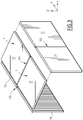
- the Figure 1 has an air diffusion duct 1 for an aeration system according to an exemplary embodiment of the invention.
- the ventilation system is example intended to equip a rail vehicle such as for example of the type carrying passengers such as a metro or a tram.
- the sheath 1 comprises a plurality of elements 3 assembled together and fixed to a ceiling structure 5 of the railway vehicle.
- the elements 3 together form at least one air distribution duct 7, 8.
- the duct 7, 8 is generally supplied by propulsion means (not shown) which propel the air inside the duct 7, 8.
- Propellant means may for example be associated with an air conditioning or heating unit capable of cooling or heating the air propelled into the duct 7, 8.
- Each element 3 comprises at least one hollow volume delimited by an upper wall 9 and a lower wall 11 extending in the longitudinal direction X of the vehicle and two side walls 13, 15 substantially perpendicular to the upper and lower walls 9 and 11.
- Each element 3 comprises an upper profile 17 in the shape of an inverted U forming the side walls 13, 15 and upper 9 of said element 3.
- the bottom wall 11 is formed by a ceiling wall 18 intended to be removably attached to the structure of the ceiling 5.
- the ceiling wall 18 is, for example, equipped with a rigid insulating panel.
- the upper profile 17 and the central ceiling wall 18 comprise self-supporting insulating panels.
- the upper profile 17 and the central ceiling wall 18 advantageously comprise rigid self-supporting foam panels, more particularly with closed cells.
- the rigid foam panels are polyisocyanurate coated with two embossed aluminum surfaces of PIR-ALU® type.
- the panels are, for example, insulators.
- the thickness of the panels is greater than 15 mm, for example substantially equal to 20 mm.
- the density of the material composing the panels is, for example, between 35 kg / m 3 and 45 kg / m 3 , for example 40 kg / m 3 .
- the maximum length of the panels is several meters, typically 4 m.
- the panels of PIR-ALU® have a high rigidity and are also very light.
- a sheath 1 designed PIR-ALU® has a mass of about 7 kg per linear meter against about 20 kg per linear meter for a aluminum sheath of the state of the art. Thus, the handling operations are facilitated and do not require the use of specific heavy means such as cranes.
- the embossed aluminum coating acts as a barrier against steam.
- the insulating properties of the closed-cell foam avoid the appearance of moisture and maintain the desired temperature of the air flowing in the conduit 7.
- sheath according to the invention does not require the addition of a coating additional insulation to meet thermal stresses.
- the panels are made of a material that has the same thermal and insulating properties as PIR-ALU®.
- the panels are for example designed in a material having a density similar to that of PIR-ALU®, typically between 0.25 and 0.45.
- the upper profile 17 comprises two side panels 19, 21, said left side panel and right side panel, and an upper panel 23, the side panels 19, 21 being fixed by snapping perpendicularly to the panel upper 23 by first fastening means comprising left and right pultruded snap profiles 27.
- the upper profile 17, the left-side panel 19 and / or the right-hand side panel 21 are furthermore glued to the left and right pultruded click-fit profiles 27.
- the pultruded snap profiles 25, 27 make it possible to assemble the left and right ends 30 of the upper profile 17 respectively to the left and right side panels 19 and 21.
- the upper panel 23 and the side panels 19, 21 of an element 3 have an identical length, typically of the order of a few meters, at most about 4 m.
- the left 19 and right 21 side panels of an element 3 are substantially identical. They have a width of the order of a few tens of centimeters, for example 20 cm.
- the left and right pultruded profiles 25 each comprise two fixing housings 31, 33 by snap-fastening of the upper and lateral panels 19, 21.
- the fixing housings 31, 33 extend over the entire length of the upper section 17, according to the longitudinal direction X.
- the first fixing housing 31 of the left pultruded section 25 comprises an upper wall 35, a lower wall 37 and a side wall 39 which define a groove 41 whose opening is oriented towards the left lateral wall of the upper panel 23.
- a putty adhesive is, for example, added between the side wall 39 of the first fixing housing 31 and the left end 29 of the upper profile 17.
- the bottom wall 37 and the side wall 39 of the first attachment housing 31 are substantially planar.
- the side wall 39 has a length substantially greater than the thickness of the upper panel 23.
- the upper wall 35 of the first attachment housing has a recess 43 inward of the groove 41 so that when the top panel 23 is inserted into the groove 41 by forcing, the upper wall 35 of the first mounting housing 31 is supported on the upper panel 23 in the longitudinal direction, keeping the upper panel 23 in the groove 41.
- the second mounting housing 33 has an upper wall 45, coinciding with the lower wall 37 of the first housing 31, and two left side walls 47 and 49 that define a right-angled groove 51 facing towards the face. upper left side panel 19.
- the left side wall 47 is substantially planar.
- the right side wall 49 of the second mounting housing 33 has a recess 53 inwardly of the groove 51 so that when the left side panel 19 is inserted into the groove 51 forcing, the right side wall 49 of the second attachment housing 33 bears on the left side panel 19 in the longitudinal direction, keeping the left side panel 19 in the groove 51.
- the right side panel 21 is fastened in a manner similar to that described above, by snapping into the upper panel 23 by means of the right pultruded profile 27.
- the right pultruded section 27 has a structure identical to that of the left pultruded profile 25 .
- the pultruded profiles 25, 27 are made of a composite material, for example glass fiber reinforced polyester (GRP) in order to give them a lightness and great strength similar to that of steel and to avoid thermal bridges.
- GRP glass fiber reinforced polyester
- the pultruded sections 25, 27 and the snap-fastening mode make it easy to assemble the different walls of the upper profile 17 and ensure a good mechanical hold between the various elements.
- the element 3 comprises at least one internal separation partition 55 of the hollow volume, extending between the upper wall 9 and lower 11, said partition 55 being inclined or parallel with respect to the side walls 13, 15.
- the element 3 comprises an internal partition 55 inclined with respect to the side walls 13, 15, that is to say disposed obliquely with respect to the longitudinal direction X of the sheath 1 so as to forming two symmetrical conduits 7, 8 with variable sections.
- the air propellant means (not shown) are located at the widest ends of the ducts and feed these ducts 7, 8 in air.
- the upper panel 23 comprises a left element 57 and a straight element 59 having a substantially trapezoidal shape as visible on the Figure 1 .
- the internal partition 55 is fixed to the two left 57 and right 59 elements of the upper panel 23 by means of a central pultruded section 61.
- the central pultruded section 61 comprises three fixing housings 63, 65 and 67.
- the first mounting housing 63 has a right upper wall 69, a central wall 71, and a lower right wall 73 defining a first groove 75 facing to the right towards the right member 59 of the top panel.
- the upper wall 69 of the first attachment housing 63 is supported on the upper wall of the right element 59 holding the right element 59 to the inside the first groove 75.
- the second attachment housing 65 has a left upper wall 77, a lower wall 79 and a central wall 81 which define a second groove 83 facing to the left towards the left member 57 of the top panel 23.
- the upper wall 77 of the second attachment housing 65 bears on the upper wall of the left-hand member 57, keeping the left-hand member 57 in place. inside the second groove 83.
- the third attachment housing 67 has an upper wall 85 and two side walls 87 which define a third groove 89 facing downwards towards the internal partition wall 55.
- the side walls 87 are inclined inwardly of the third groove 89 so that, when the internal partition wall 55 is forcibly inserted into the third attachment housing 67, the two side walls 87 of the third mounting housing 67 are supported on the internal partition 55, maintaining the internal partition 55 inside the third groove 89.
- the internal partition 55 thus makes it possible on the one hand to ensure the stiffening of the sheath 1 and on the other hand it constitutes a means for guiding the air inside the sheath 1.
- a hollow seal 104 for example made of silicone, is arranged between the wall 18 and the internal partition 55.
- the seal 104 makes it possible in particular to provide a seal between the wall 18 and the internal partition 55.
- the seal 104 is, for example, latched and previously bonded to the internal partition 55.
- the upper profile 17 is snap-fastened to the structure of the ceiling 5 of the vehicle.
- the side panels 19, 21 of the upper profile 17 are fixed to the structure of the ceiling 5 of the vehicle by second fixing means comprising two U-shaped ceiling profiles 91 which extend in the longitudinal direction.
- Each ceiling profile 91 has a bottom face 93 and two side faces 95 defining a groove 97.
- the lower face 93 is substantially flat and is fixed on the structure of the ceiling 5 of the vehicle.
- the side faces 95 each comprise a recess 99 towards the inside of the groove 97 so that when the side panels 19, 21 of the upper profile 17 are forced into the groove 97, the side faces 95 of the ceiling profile 91 bear on the inner and outer faces of the side panels 19, 21 of the upper profile 17, keeping the side panels 19, 21 inside the groove 97.
- Ceiling profiles 91 are for example aluminum.
- the first fastening means between the side panels 19, 21 and the upper panel 23 of the upper profile 17, and the second fixing means between the upper profile 17 and the ceiling structure 5 of the vehicle comprise means of waterproof or airtight.
- the fasteners are for example masticated and covered with an adhesive sealing tape.
- the mastic used is for example MS Polymer classified Smoke Fires.
- the central ceiling wall 18 is fixed to the ceiling structure 5 of the railway vehicle by means of conventional removable fasteners 101.
- This attachment 101 is, for example, made by interlocking the central ceiling wall 18 in the ceiling structure 5.
- the central ceiling wall 18 generally comprises a plurality of panels fixed one after the other in the longitudinal direction X.
- each panel is for example fixed to the ceiling structure 5 by means of hinges, so that this panel can pivot downwards.
- each panel is fixed by reversible clipping to the ceiling structure 5.
- the elements 3 of the sheath 1 are fixed longitudinally by third fastening means 103 by splicing each other and the third fastening means 103 comprise means of sealing with water and air.
- the third attachment means 103 are, for example, a step splice, in particular a mid-wood splice, that is to say that the corresponding walls of two adjacent elements 3 are assembled by notching the respective walls on the half of their thickness, as shown in Figure 3 .
- the panels are notched about 10 mm.
- the corresponding walls of two adjacent elements 3 are fixed by gluing.
- the assembly of the panels is done for example by applying mastic glue.
- the sealant used is, for example, MS Polymer base classified Smoke fires.
- an adhesive aluminum strip is typically placed outside the sheath along the junction made.
- the assembly of two elements 3 is simple and does not require complex fastening devices such as toggle systems for example.
- the uppermost U-shaped upper profile 17 and the ceiling central wall 18, formed by self-supporting rigid foam panels, are provided.
- the upper profile 17 is then attached to the structure of the ceiling 5 of the vehicle in the longitudinal direction. Fixing is performed by snapping as described above.
- the central wall of the ceiling 18 is then removably fixed, defining with the upper profile 17, a hollow air distribution volume extending in the longitudinal direction X of the vehicle.
- the upper profile 17 is formed by snapping the side panels 19, 21 of the upper profile 17 to the upper panel 23 of the upper profile 17 by the first fixing means comprising the pultruded snap-fastening profiles 25, 27 as previously described.
- the sheath 1 can easily be handled without the use of heavy machinery.
- the sheath 1 can thus be more easily installed inside the railway vehicle.
- the sheath 1 according to the invention is about 60% lighter while having the same thermal and sealing properties required for this type of equipment.
- the design of the PIR-ALU® panel top section 17 is easy and the availability of large PIR-ALU® panels (around 4 meters in length) makes it possible to limit the number of elements. which make up the sheath 1. The connections between the elements 3 are therefore limited and the risk of potential air leakage is reduced.
- the removable central ceiling wall 18 facilitates cleaning operations of the sheath 1 by avoiding the use of complex suction systems and brushes, and thus prevent premature damage to the sheath 1.
- the manufacturing cost of the sheath 1 according to the invention is substantially reduced, of the order of 60% compared to a sheath of the state of the art.
- the internal partition 55 is devoid of hollow seal 104 between the central ceiling wall 18 and the internal partition 55.
- a U-shaped ceiling profile similar to the profiles 91 holding the side panels 19, 21 is, for example, fixed on the structure of the ceiling 5 of the vehicle obliquely relative to the longitudinal direction X of the sheath 1, the inner partition 55 being snapped into said profile during the installation of the sheath. Such snapping allows in particular to achieve a seal at this level.
Landscapes
- Engineering & Computer Science (AREA)
- Mechanical Engineering (AREA)
- Body Structure For Vehicles (AREA)
- Air-Conditioning For Vehicles (AREA)
- Duct Arrangements (AREA)
Priority Applications (1)
| Application Number | Priority Date | Filing Date | Title |
|---|---|---|---|
| PL18175465T PL3409558T3 (pl) | 2017-06-02 | 2018-06-01 | Kanał dyfuzyjny powietrza dla systemu napowietrzania, w szczególności w pojazdach kolejowych |
Applications Claiming Priority (1)
| Application Number | Priority Date | Filing Date | Title |
|---|---|---|---|
| FR1754946A FR3066986B1 (fr) | 2017-06-02 | 2017-06-02 | Gaine de diffusion d'air pour systeme d'aeration, notamment de vehicule ferroviaire |
Publications (2)
| Publication Number | Publication Date |
|---|---|
| EP3409558A1 true EP3409558A1 (de) | 2018-12-05 |
| EP3409558B1 EP3409558B1 (de) | 2021-03-03 |
Family
ID=59746071
Family Applications (1)
| Application Number | Title | Priority Date | Filing Date |
|---|---|---|---|
| EP18175465.6A Active EP3409558B1 (de) | 2017-06-02 | 2018-06-01 | Luftverteilungskanal für belüftungssystem, insbesondere für schienenfahrzeug |
Country Status (6)
| Country | Link |
|---|---|
| EP (1) | EP3409558B1 (de) |
| BR (1) | BR102018011039A2 (de) |
| ES (1) | ES2870963T3 (de) |
| FR (1) | FR3066986B1 (de) |
| PL (1) | PL3409558T3 (de) |
| ZA (1) | ZA201803658B (de) |
Citations (6)
| Publication number | Priority date | Publication date | Assignee | Title |
|---|---|---|---|---|
| DE8912822U1 (de) * | 1989-10-30 | 1990-02-15 | Linke-Hofmann-Busch Waggon-Fahrzeug-Maschinen Gmbh, 3320 Salzgitter | Luftkanal für Fahrzeuge, insbesondere für Schienenfahrzeuge |
| DE4300713C1 (de) * | 1993-01-14 | 1994-02-03 | Talbot Waggonfab | Befestigungsanordnung für einen Deckenkanal |
| EP2335954A1 (de) * | 2009-12-18 | 2011-06-22 | Bombardier Transportation GmbH | Anordnung zur Befestigung an einer Wagenkasten-Decke eines Großraum-Fahrzeuges zur Personenbeförderung |
| EP2957476A1 (de) * | 2013-02-12 | 2015-12-23 | Kawasaki Jukogyo Kabushiki Kaisha | Kanal für eine fahrzeugklimaanlage und schienenfahrzeug |
| WO2016012397A1 (de) * | 2014-07-24 | 2016-01-28 | Bombardier Transportation Gmbh | Luftverteileinrichtung für den innenraum eines schienenfahrzeugs |
| EP3127774A1 (de) * | 2015-08-06 | 2017-02-08 | Bombardier Transportation GmbH | In die karosseriedachprofile integriertes luftkanalsystem |
-
2017
- 2017-06-02 FR FR1754946A patent/FR3066986B1/fr not_active Expired - Fee Related
-
2018
- 2018-05-30 BR BR102018011039-0A patent/BR102018011039A2/pt not_active IP Right Cessation
- 2018-06-01 EP EP18175465.6A patent/EP3409558B1/de active Active
- 2018-06-01 PL PL18175465T patent/PL3409558T3/pl unknown
- 2018-06-01 ZA ZA2018/03658A patent/ZA201803658B/en unknown
- 2018-06-01 ES ES18175465T patent/ES2870963T3/es active Active
Patent Citations (6)
| Publication number | Priority date | Publication date | Assignee | Title |
|---|---|---|---|---|
| DE8912822U1 (de) * | 1989-10-30 | 1990-02-15 | Linke-Hofmann-Busch Waggon-Fahrzeug-Maschinen Gmbh, 3320 Salzgitter | Luftkanal für Fahrzeuge, insbesondere für Schienenfahrzeuge |
| DE4300713C1 (de) * | 1993-01-14 | 1994-02-03 | Talbot Waggonfab | Befestigungsanordnung für einen Deckenkanal |
| EP2335954A1 (de) * | 2009-12-18 | 2011-06-22 | Bombardier Transportation GmbH | Anordnung zur Befestigung an einer Wagenkasten-Decke eines Großraum-Fahrzeuges zur Personenbeförderung |
| EP2957476A1 (de) * | 2013-02-12 | 2015-12-23 | Kawasaki Jukogyo Kabushiki Kaisha | Kanal für eine fahrzeugklimaanlage und schienenfahrzeug |
| WO2016012397A1 (de) * | 2014-07-24 | 2016-01-28 | Bombardier Transportation Gmbh | Luftverteileinrichtung für den innenraum eines schienenfahrzeugs |
| EP3127774A1 (de) * | 2015-08-06 | 2017-02-08 | Bombardier Transportation GmbH | In die karosseriedachprofile integriertes luftkanalsystem |
Also Published As
| Publication number | Publication date |
|---|---|
| EP3409558B1 (de) | 2021-03-03 |
| FR3066986B1 (fr) | 2020-08-28 |
| FR3066986A1 (fr) | 2018-12-07 |
| ZA201803658B (en) | 2021-06-30 |
| ES2870963T3 (es) | 2021-10-28 |
| BR102018011039A2 (pt) | 2019-04-09 |
| PL3409558T3 (pl) | 2021-09-13 |
Similar Documents
| Publication | Publication Date | Title |
|---|---|---|
| EP0772009B1 (de) | Lüftungskanal und Isolierplatten für seine Auskleidung | |
| EP1862366B1 (de) | Seitenwand des Wagenkastens eines Schienenfahrzeugs | |
| EP2791441B1 (de) | Wärmedämmsystem und entsprechendes montageverfahren | |
| EP2136412A2 (de) | Perfektionierung der Halterungsmittel für Solarmodule | |
| EP2791440B1 (de) | Wärmedämmungssystem mit zwischenlagern zum halten von vip-platten und entsprechendes montageverfahren | |
| EP3115525A1 (de) | Verstellbare und isolierende blende für eine sonnenschutzanlage | |
| FR2460823A1 (fr) | Revetement interne destine au plafond de vehicules, notamment ferroviaires | |
| EP2977287B1 (de) | Paneel für die Ausbildung eines Schienenfahrzeugkastens und Verfahren zur Herstellung desselben | |
| EP3409558B1 (de) | Luftverteilungskanal für belüftungssystem, insbesondere für schienenfahrzeug | |
| EP1052362A2 (de) | Doppelverglasung | |
| EP2412613A1 (de) | Karosseriemodul für Kühlfahrzeug mit Vakuum-Isolierpaneel, und entsprechendes Herstellungsverfahren | |
| EP3196372B1 (de) | Wärmedämmsystem und -verfahren, bei dem verbundpaneele zur definition einer dämmschicht für vip-elemente verwendet werden | |
| EP1614563B1 (de) | Träger im Fahrzeuginnenraum für eine Luftversorgungseinrichtungeinheit einer Klima-Anlage. | |
| EP2740877A1 (de) | Rollladenkasteneinheit mit einem mit Isoliermaterial ausgestatteten Rollladenkasten | |
| WO2014128378A1 (fr) | Procédé et système de doublage de paroi, adapté pour le maintien de panneaux piv et kit de fixation associé | |
| EP2671782A1 (de) | Karosseriemodul für ein Kühlfahrzeug mit einem Vakuumisolationspaneel, und dessen Herstellungsverfahren. | |
| EP3656633B1 (de) | Waggon eines schienenfahrzeugs | |
| EP1150409A1 (de) | Kabelrinnenabschnitte und daraus hergestellte Kabelrinne durch Verbinbung von mindestens zwei Abschnitten und deren Herstellungsverfahren | |
| FR2740804A1 (fr) | Gaine de ventilation et panneau isolant utilise pour son revetement interne | |
| FR3036357A1 (fr) | Systeme de conditionnement d'air pour vehicule de type ferroviaire | |
| FR2959556A1 (fr) | Panneau solaire parallelepipedique avec support pour la pose sur une structure de reception | |
| FR2872741A1 (fr) | Module d'acheminement et de distribution d'air en provenance d'un ensemble thermique d'une installation de chauffage, de ventilation et/ou de climatisation pour habitacle de vehicule | |
| WO2009013400A1 (fr) | Element de cheminement de cables, et procede de fabrication de cet element | |
| FR3147062A1 (fr) | Perfectionnement aux supports de modules photovoltaïques | |
| EP0774550A1 (de) | Wand oder Abtrennung mit auf ein Tragwerk beweglich montierte Platten |
Legal Events
| Date | Code | Title | Description |
|---|---|---|---|
| PUAI | Public reference made under article 153(3) epc to a published international application that has entered the european phase |
Free format text: ORIGINAL CODE: 0009012 |
|
| STAA | Information on the status of an ep patent application or granted ep patent |
Free format text: STATUS: THE APPLICATION HAS BEEN PUBLISHED |
|
| AK | Designated contracting states |
Kind code of ref document: A1 Designated state(s): AL AT BE BG CH CY CZ DE DK EE ES FI FR GB GR HR HU IE IS IT LI LT LU LV MC MK MT NL NO PL PT RO RS SE SI SK SM TR |
|
| AX | Request for extension of the european patent |
Extension state: BA ME |
|
| STAA | Information on the status of an ep patent application or granted ep patent |
Free format text: STATUS: REQUEST FOR EXAMINATION WAS MADE |
|
| 17P | Request for examination filed |
Effective date: 20181220 |
|
| RBV | Designated contracting states (corrected) |
Designated state(s): AL AT BE BG CH CY CZ DE DK EE ES FI FR GB GR HR HU IE IS IT LI LT LU LV MC MK MT NL NO PL PT RO RS SE SI SK SM TR |
|
| GRAP | Despatch of communication of intention to grant a patent |
Free format text: ORIGINAL CODE: EPIDOSNIGR1 |
|
| STAA | Information on the status of an ep patent application or granted ep patent |
Free format text: STATUS: GRANT OF PATENT IS INTENDED |
|
| INTG | Intention to grant announced |
Effective date: 20201014 |
|
| GRAS | Grant fee paid |
Free format text: ORIGINAL CODE: EPIDOSNIGR3 |
|
| GRAA | (expected) grant |
Free format text: ORIGINAL CODE: 0009210 |
|
| STAA | Information on the status of an ep patent application or granted ep patent |
Free format text: STATUS: THE PATENT HAS BEEN GRANTED |
|
| AK | Designated contracting states |
Kind code of ref document: B1 Designated state(s): AL AT BE BG CH CY CZ DE DK EE ES FI FR GB GR HR HU IE IS IT LI LT LU LV MC MK MT NL NO PL PT RO RS SE SI SK SM TR |
|
| REG | Reference to a national code |
Ref country code: GB Ref legal event code: FG4D Free format text: NOT ENGLISH |
|
| REG | Reference to a national code |
Ref country code: AT Ref legal event code: REF Ref document number: 1366910 Country of ref document: AT Kind code of ref document: T Effective date: 20210315 Ref country code: CH Ref legal event code: EP |
|
| REG | Reference to a national code |
Ref country code: DE Ref legal event code: R096 Ref document number: 602018013251 Country of ref document: DE |
|
| REG | Reference to a national code |
Ref country code: IE Ref legal event code: FG4D Free format text: LANGUAGE OF EP DOCUMENT: FRENCH |
|
| REG | Reference to a national code |
Ref country code: LT Ref legal event code: MG9D |
|
| PG25 | Lapsed in a contracting state [announced via postgrant information from national office to epo] |
Ref country code: BG Free format text: LAPSE BECAUSE OF FAILURE TO SUBMIT A TRANSLATION OF THE DESCRIPTION OR TO PAY THE FEE WITHIN THE PRESCRIBED TIME-LIMIT Effective date: 20210603 Ref country code: FI Free format text: LAPSE BECAUSE OF FAILURE TO SUBMIT A TRANSLATION OF THE DESCRIPTION OR TO PAY THE FEE WITHIN THE PRESCRIBED TIME-LIMIT Effective date: 20210303 Ref country code: GR Free format text: LAPSE BECAUSE OF FAILURE TO SUBMIT A TRANSLATION OF THE DESCRIPTION OR TO PAY THE FEE WITHIN THE PRESCRIBED TIME-LIMIT Effective date: 20210604 Ref country code: HR Free format text: LAPSE BECAUSE OF FAILURE TO SUBMIT A TRANSLATION OF THE DESCRIPTION OR TO PAY THE FEE WITHIN THE PRESCRIBED TIME-LIMIT Effective date: 20210303 Ref country code: NO Free format text: LAPSE BECAUSE OF FAILURE TO SUBMIT A TRANSLATION OF THE DESCRIPTION OR TO PAY THE FEE WITHIN THE PRESCRIBED TIME-LIMIT Effective date: 20210603 Ref country code: LT Free format text: LAPSE BECAUSE OF FAILURE TO SUBMIT A TRANSLATION OF THE DESCRIPTION OR TO PAY THE FEE WITHIN THE PRESCRIBED TIME-LIMIT Effective date: 20210303 |
|
| REG | Reference to a national code |
Ref country code: NL Ref legal event code: MP Effective date: 20210303 |
|
| REG | Reference to a national code |
Ref country code: AT Ref legal event code: MK05 Ref document number: 1366910 Country of ref document: AT Kind code of ref document: T Effective date: 20210303 |
|
| PG25 | Lapsed in a contracting state [announced via postgrant information from national office to epo] |
Ref country code: RS Free format text: LAPSE BECAUSE OF FAILURE TO SUBMIT A TRANSLATION OF THE DESCRIPTION OR TO PAY THE FEE WITHIN THE PRESCRIBED TIME-LIMIT Effective date: 20210303 Ref country code: LV Free format text: LAPSE BECAUSE OF FAILURE TO SUBMIT A TRANSLATION OF THE DESCRIPTION OR TO PAY THE FEE WITHIN THE PRESCRIBED TIME-LIMIT Effective date: 20210303 Ref country code: SE Free format text: LAPSE BECAUSE OF FAILURE TO SUBMIT A TRANSLATION OF THE DESCRIPTION OR TO PAY THE FEE WITHIN THE PRESCRIBED TIME-LIMIT Effective date: 20210303 |
|
| PG25 | Lapsed in a contracting state [announced via postgrant information from national office to epo] |
Ref country code: NL Free format text: LAPSE BECAUSE OF FAILURE TO SUBMIT A TRANSLATION OF THE DESCRIPTION OR TO PAY THE FEE WITHIN THE PRESCRIBED TIME-LIMIT Effective date: 20210303 |
|
| REG | Reference to a national code |
Ref country code: ES Ref legal event code: FG2A Ref document number: 2870963 Country of ref document: ES Kind code of ref document: T3 Effective date: 20211028 |
|
| PG25 | Lapsed in a contracting state [announced via postgrant information from national office to epo] |
Ref country code: AT Free format text: LAPSE BECAUSE OF FAILURE TO SUBMIT A TRANSLATION OF THE DESCRIPTION OR TO PAY THE FEE WITHIN THE PRESCRIBED TIME-LIMIT Effective date: 20210303 Ref country code: SM Free format text: LAPSE BECAUSE OF FAILURE TO SUBMIT A TRANSLATION OF THE DESCRIPTION OR TO PAY THE FEE WITHIN THE PRESCRIBED TIME-LIMIT Effective date: 20210303 Ref country code: CZ Free format text: LAPSE BECAUSE OF FAILURE TO SUBMIT A TRANSLATION OF THE DESCRIPTION OR TO PAY THE FEE WITHIN THE PRESCRIBED TIME-LIMIT Effective date: 20210303 Ref country code: EE Free format text: LAPSE BECAUSE OF FAILURE TO SUBMIT A TRANSLATION OF THE DESCRIPTION OR TO PAY THE FEE WITHIN THE PRESCRIBED TIME-LIMIT Effective date: 20210303 |
|
| PG25 | Lapsed in a contracting state [announced via postgrant information from national office to epo] |
Ref country code: PT Free format text: LAPSE BECAUSE OF FAILURE TO SUBMIT A TRANSLATION OF THE DESCRIPTION OR TO PAY THE FEE WITHIN THE PRESCRIBED TIME-LIMIT Effective date: 20210705 Ref country code: RO Free format text: LAPSE BECAUSE OF FAILURE TO SUBMIT A TRANSLATION OF THE DESCRIPTION OR TO PAY THE FEE WITHIN THE PRESCRIBED TIME-LIMIT Effective date: 20210303 Ref country code: SK Free format text: LAPSE BECAUSE OF FAILURE TO SUBMIT A TRANSLATION OF THE DESCRIPTION OR TO PAY THE FEE WITHIN THE PRESCRIBED TIME-LIMIT Effective date: 20210303 Ref country code: IS Free format text: LAPSE BECAUSE OF FAILURE TO SUBMIT A TRANSLATION OF THE DESCRIPTION OR TO PAY THE FEE WITHIN THE PRESCRIBED TIME-LIMIT Effective date: 20210703 |
|
| REG | Reference to a national code |
Ref country code: DE Ref legal event code: R097 Ref document number: 602018013251 Country of ref document: DE |
|
| PLBE | No opposition filed within time limit |
Free format text: ORIGINAL CODE: 0009261 |
|
| STAA | Information on the status of an ep patent application or granted ep patent |
Free format text: STATUS: NO OPPOSITION FILED WITHIN TIME LIMIT |
|
| PG25 | Lapsed in a contracting state [announced via postgrant information from national office to epo] |
Ref country code: DK Free format text: LAPSE BECAUSE OF FAILURE TO SUBMIT A TRANSLATION OF THE DESCRIPTION OR TO PAY THE FEE WITHIN THE PRESCRIBED TIME-LIMIT Effective date: 20210303 Ref country code: AL Free format text: LAPSE BECAUSE OF FAILURE TO SUBMIT A TRANSLATION OF THE DESCRIPTION OR TO PAY THE FEE WITHIN THE PRESCRIBED TIME-LIMIT Effective date: 20210303 Ref country code: MC Free format text: LAPSE BECAUSE OF FAILURE TO SUBMIT A TRANSLATION OF THE DESCRIPTION OR TO PAY THE FEE WITHIN THE PRESCRIBED TIME-LIMIT Effective date: 20210303 |
|
| REG | Reference to a national code |
Ref country code: CH Ref legal event code: PL |
|
| 26N | No opposition filed |
Effective date: 20211206 |
|
| PG25 | Lapsed in a contracting state [announced via postgrant information from national office to epo] |
Ref country code: SI Free format text: LAPSE BECAUSE OF FAILURE TO SUBMIT A TRANSLATION OF THE DESCRIPTION OR TO PAY THE FEE WITHIN THE PRESCRIBED TIME-LIMIT Effective date: 20210303 |
|
| REG | Reference to a national code |
Ref country code: BE Ref legal event code: MM Effective date: 20210630 |
|
| PG25 | Lapsed in a contracting state [announced via postgrant information from national office to epo] |
Ref country code: LU Free format text: LAPSE BECAUSE OF NON-PAYMENT OF DUE FEES Effective date: 20210601 |
|
| PG25 | Lapsed in a contracting state [announced via postgrant information from national office to epo] |
Ref country code: LI Free format text: LAPSE BECAUSE OF NON-PAYMENT OF DUE FEES Effective date: 20210630 Ref country code: IE Free format text: LAPSE BECAUSE OF NON-PAYMENT OF DUE FEES Effective date: 20210601 Ref country code: CH Free format text: LAPSE BECAUSE OF NON-PAYMENT OF DUE FEES Effective date: 20210630 |
|
| PG25 | Lapsed in a contracting state [announced via postgrant information from national office to epo] |
Ref country code: IS Free format text: LAPSE BECAUSE OF FAILURE TO SUBMIT A TRANSLATION OF THE DESCRIPTION OR TO PAY THE FEE WITHIN THE PRESCRIBED TIME-LIMIT Effective date: 20210703 |
|
| PG25 | Lapsed in a contracting state [announced via postgrant information from national office to epo] |
Ref country code: BE Free format text: LAPSE BECAUSE OF NON-PAYMENT OF DUE FEES Effective date: 20210630 |
|
| PG25 | Lapsed in a contracting state [announced via postgrant information from national office to epo] |
Ref country code: CY Free format text: LAPSE BECAUSE OF FAILURE TO SUBMIT A TRANSLATION OF THE DESCRIPTION OR TO PAY THE FEE WITHIN THE PRESCRIBED TIME-LIMIT Effective date: 20210303 |
|
| PG25 | Lapsed in a contracting state [announced via postgrant information from national office to epo] |
Ref country code: HU Free format text: LAPSE BECAUSE OF FAILURE TO SUBMIT A TRANSLATION OF THE DESCRIPTION OR TO PAY THE FEE WITHIN THE PRESCRIBED TIME-LIMIT; INVALID AB INITIO Effective date: 20180601 |
|
| P01 | Opt-out of the competence of the unified patent court (upc) registered |
Effective date: 20230823 |
|
| PG25 | Lapsed in a contracting state [announced via postgrant information from national office to epo] |
Ref country code: MK Free format text: LAPSE BECAUSE OF FAILURE TO SUBMIT A TRANSLATION OF THE DESCRIPTION OR TO PAY THE FEE WITHIN THE PRESCRIBED TIME-LIMIT Effective date: 20210303 |
|
| PG25 | Lapsed in a contracting state [announced via postgrant information from national office to epo] |
Ref country code: TR Free format text: LAPSE BECAUSE OF FAILURE TO SUBMIT A TRANSLATION OF THE DESCRIPTION OR TO PAY THE FEE WITHIN THE PRESCRIBED TIME-LIMIT Effective date: 20210303 |
|
| PG25 | Lapsed in a contracting state [announced via postgrant information from national office to epo] |
Ref country code: MT Free format text: LAPSE BECAUSE OF FAILURE TO SUBMIT A TRANSLATION OF THE DESCRIPTION OR TO PAY THE FEE WITHIN THE PRESCRIBED TIME-LIMIT Effective date: 20210303 |
|
| REG | Reference to a national code |
Ref country code: GB Ref legal event code: 732E Free format text: REGISTERED BETWEEN 20250213 AND 20250219 |
|
| REG | Reference to a national code |
Ref country code: ES Ref legal event code: PC2A Owner name: ALSTOM HOLDINGS Effective date: 20250310 |
|
| PGFP | Annual fee paid to national office [announced via postgrant information from national office to epo] |
Ref country code: PL Payment date: 20250522 Year of fee payment: 8 Ref country code: DE Payment date: 20250618 Year of fee payment: 8 |
|
| PGFP | Annual fee paid to national office [announced via postgrant information from national office to epo] |
Ref country code: GB Payment date: 20250618 Year of fee payment: 8 |
|
| PGFP | Annual fee paid to national office [announced via postgrant information from national office to epo] |
Ref country code: FR Payment date: 20250625 Year of fee payment: 8 |
|
| PGFP | Annual fee paid to national office [announced via postgrant information from national office to epo] |
Ref country code: ES Payment date: 20250728 Year of fee payment: 8 |
|
| PGFP | Annual fee paid to national office [announced via postgrant information from national office to epo] |
Ref country code: IT Payment date: 20250624 Year of fee payment: 8 |