EP3409624A1 - Schwimmende zuführungsunterstützungseinheit zur ausgabe von in grossmengen verpacktem schweissdraht - Google Patents
Schwimmende zuführungsunterstützungseinheit zur ausgabe von in grossmengen verpacktem schweissdraht Download PDFInfo
- Publication number
- EP3409624A1 EP3409624A1 EP18184506.6A EP18184506A EP3409624A1 EP 3409624 A1 EP3409624 A1 EP 3409624A1 EP 18184506 A EP18184506 A EP 18184506A EP 3409624 A1 EP3409624 A1 EP 3409624A1
- Authority
- EP
- European Patent Office
- Prior art keywords
- ribs
- wire
- assist unit
- base portion
- feed assist
- Prior art date
- Legal status (The legal status is an assumption and is not a legal conclusion. Google has not performed a legal analysis and makes no representation as to the accuracy of the status listed.)
- Withdrawn
Links
- 238000003466 welding Methods 0.000 title claims abstract description 12
- 238000000034 method Methods 0.000 claims abstract description 13
- 239000000463 material Substances 0.000 description 5
- 229910000831 Steel Inorganic materials 0.000 description 3
- 239000010959 steel Substances 0.000 description 3
- 229910000838 Al alloy Inorganic materials 0.000 description 2
- 229910000906 Bronze Inorganic materials 0.000 description 1
- RYGMFSIKBFXOCR-UHFFFAOYSA-N Copper Chemical compound [Cu] RYGMFSIKBFXOCR-UHFFFAOYSA-N 0.000 description 1
- 239000004677 Nylon Substances 0.000 description 1
- 229910045601 alloy Inorganic materials 0.000 description 1
- 239000000956 alloy Substances 0.000 description 1
- 230000004075 alteration Effects 0.000 description 1
- XAGFODPZIPBFFR-UHFFFAOYSA-N aluminium Chemical compound [Al] XAGFODPZIPBFFR-UHFFFAOYSA-N 0.000 description 1
- 229910052782 aluminium Inorganic materials 0.000 description 1
- 230000008901 benefit Effects 0.000 description 1
- 239000010974 bronze Substances 0.000 description 1
- 229910052802 copper Inorganic materials 0.000 description 1
- 239000010949 copper Substances 0.000 description 1
- 230000006870 function Effects 0.000 description 1
- 238000012986 modification Methods 0.000 description 1
- 230000004048 modification Effects 0.000 description 1
- 229920001778 nylon Polymers 0.000 description 1
- 239000002861 polymer material Substances 0.000 description 1
- 230000008569 process Effects 0.000 description 1
- 239000010935 stainless steel Substances 0.000 description 1
- 229910001220 stainless steel Inorganic materials 0.000 description 1
Images






Classifications
-
- B—PERFORMING OPERATIONS; TRANSPORTING
- B65—CONVEYING; PACKING; STORING; HANDLING THIN OR FILAMENTARY MATERIAL
- B65H—HANDLING THIN OR FILAMENTARY MATERIAL, e.g. SHEETS, WEBS, CABLES
- B65H57/00—Guides for filamentary materials; Supports therefor
- B65H57/18—Guides for filamentary materials; Supports therefor mounted to facilitate unwinding of material from packages
- B65H57/20—Flyers
-
- B—PERFORMING OPERATIONS; TRANSPORTING
- B23—MACHINE TOOLS; METAL-WORKING NOT OTHERWISE PROVIDED FOR
- B23K—SOLDERING OR UNSOLDERING; WELDING; CLADDING OR PLATING BY SOLDERING OR WELDING; CUTTING BY APPLYING HEAT LOCALLY, e.g. FLAME CUTTING; WORKING BY LASER BEAM
- B23K9/00—Arc welding or cutting
- B23K9/12—Automatic feeding or moving of electrodes or work for spot or seam welding or cutting
- B23K9/133—Means for feeding electrodes, e.g. drums, rolls, motors
- B23K9/1333—Dereeling means
-
- B—PERFORMING OPERATIONS; TRANSPORTING
- B65—CONVEYING; PACKING; STORING; HANDLING THIN OR FILAMENTARY MATERIAL
- B65H—HANDLING THIN OR FILAMENTARY MATERIAL, e.g. SHEETS, WEBS, CABLES
- B65H49/00—Unwinding or paying-out filamentary material; Supporting, storing or transporting packages from which filamentary material is to be withdrawn or paid-out
- B65H49/02—Methods or apparatus in which packages do not rotate
- B65H49/04—Package-supporting devices
- B65H49/06—Package-supporting devices for a single operative package
- B65H49/08—Package-supporting devices for a single operative package enclosing the package
-
- B—PERFORMING OPERATIONS; TRANSPORTING
- B65—CONVEYING; PACKING; STORING; HANDLING THIN OR FILAMENTARY MATERIAL
- B65H—HANDLING THIN OR FILAMENTARY MATERIAL, e.g. SHEETS, WEBS, CABLES
- B65H57/00—Guides for filamentary materials; Supports therefor
- B65H57/18—Guides for filamentary materials; Supports therefor mounted to facilitate unwinding of material from packages
-
- B—PERFORMING OPERATIONS; TRANSPORTING
- B65—CONVEYING; PACKING; STORING; HANDLING THIN OR FILAMENTARY MATERIAL
- B65H—HANDLING THIN OR FILAMENTARY MATERIAL, e.g. SHEETS, WEBS, CABLES
- B65H2701/00—Handled material; Storage means
- B65H2701/30—Handled filamentary material
- B65H2701/36—Wires
Definitions
- Embodiments of the invention generally relate to the dispensing of welding wire, and more particularly to a system and method for facilitating the dispensing of welding wire from a container.
- the drums of wire require special payoff considerations in comparison to the contrasting method of using spools. For example, it may be important to maintain downward pressure on the wire while dispensing. This pressure should be light enough to ensure that it does not inhibit the feeding of the wire, which should be smooth and consistent. However, the downward pressure should be sufficient to ensure that the wire is held in place, creating a slight amount of tension in the feeding system.
- Another product that seeks to resolve this issue is a payoff unit that utilizes a similar rotating arm.
- This device floats on the wire stack and helps to keep the twist from forming in the drum.
- this method utilizes a smooth surface that rides on the wire stack. This design fails to provide a sufficient amount of friction on the wire.
- a wire payoff system for assisting in delivering welding wire packaged in bulk drums effectively and robustly.
- the disclosed system aids in the removal of wire from a drum, where the wire will be fed through a welding system.
- the purpose of the disclosed system is to provide a feed assisting accessory that will work effectively with both "hard” and “soft” aluminum alloys, although it is not limited to aluminum alloys and can be used with wires made from various materials.
- the disclosed system enables pay off of wire consistently and free of tangles.
- a feed assist unit comprising a base portion having a plurality of ribs disposed on a lower surface thereof, the plurality of ribs extending from the lower surface.
- a dome portion can be connected to the base portion, and a rotating conduit portion can be rotatably coupled to the dome portion, the rotating conduit having a curved shape.
- Each of the plurality of ribs may have a first end disposed adjacent to the dome portion and a second end disposed adjacent to an associated side of the base portion.
- Each of the plurality of ribs may be oriented perpendicular with respect to the associated side of the base portion.
- the feed assist unit may have first and second central axes "A-A,” "B-B” oriented perpendicular to each other.
- the plurality of ribs may comprise first, second, third and fourth ribs, wherein the first and third ribs are oriented parallel to the second central axis and the second and fourth ribs are oriented parallel to the first central axis.
- the first and third ribs can be offset from the second central axis by an offset length and the second and fourth ribs can be offset from the first central axis the offset length.
- the first ends of the first, second, third and fourth ribs may be positioned at about the 11 o-clock, 2 o-clock, 5 o-clock and 8 o-clock position, respectively, with respect to the dome portion.
- a bearing can be disposed between the dome portion and the rotating conduit portion.
- the dome portion can have a height as measured from the base portion, the height being sufficient such that a first end of the rotating conduit portion does not extend past the base portion.
- the base portion can have a perimeter with a plurality of sides forming an octagonal shape.
- the ribs can be integrally formed with the base portion.
- a method of dispensing welding wire from a container includes providing a feed assist unit on top of a wire stack disposed within a container, the feed assist unit comprising: a base portion having a plurality of ribs disposed on a lower surface thereof, the plurality of ribs extending from the lower surface, and a dome portion connected to the base portion, and feeding wire from the wire stack through an opening in the dome portion.
- the method can further include directing the wire from the wire stack through a rotating conduit disposed in an opening in the dome portion, and directing the wire through the opening in the dome portion via the rotating conduit.
- the feed assist unit can further include a rotating conduit portion rotatably coupled to the dome portion via a bearing disposed in an opening in the dome portion, and wherein feeding wire from the wire stack comprises directing wire through the rotating conduit portion while the rotating conduit portion rotates with respect to the dome portion.
- the method can further include providing point contact between the plurality of ribs and top wires of the wire stack.
- Each of the plurality of ribs can have a first end disposed adjacent to the dome portion and a second end disposed adjacent to an associated side of the base portion.
- the feed assist unit can have first and second central axes oriented perpendicular to each other, and wherein the plurality of ribs comprise first, second, third and fourth ribs, wherein the first and third ribs are oriented parallel to the second central axis and the second and fourth ribs are oriented parallel to the first central axis.
- the first and third ribs can be offset from the second central axis by an offset length and the second and fourth ribs are offset from the first central axis the offset length.
- First ends of the first, second, third and fourth ribs can be positioned at about the 11 o-clock, 2 o-clock, 5 o-clock and 8 o-clock position, respectively, with respect to the dome portion.
- the dome portion can have a height as measured from the base portion, the height being sufficient such that a first end of the rotating conduit portion does not extend past the base portion.
- the disclosed feed assist unit is configured to float on a wire stack, and includes a rotating conduit sleeve for guiding the unwinding wire out of its container. Ribs are provided on the underside of the feed assist unit to provide point contact on the wire of the stack, thus enabling the wire to be consistently pulled off the stack in small amounts, thereby preventing the unraveling of large sections of loose wire that could tangle.
- the rotating section of conduit is formed in such a way as to lift the wire from the stack in a natural manner.
- the rotating conduit section is bent in two dimensions to best achieve this goal.
- the disclosed system ensures that the wire is still able to feed freely without a large amount of friction creating tension in the system.
- the feed assist unit 1 comprises a base portion 2, a dome portion 4 and a rotatable conduit portion 6.
- the base portion 2 may be generally planar and may support the dome portion 4 which is centrally disposed therein.
- the base portion 2 may include an outer periphery 8 that is sized and shaped to fit within a welding wire container.
- the rotatable conduit portion 6 may be rotatably coupled to the dome portion 4 via a bearing 10 that is disposed in an opening 12 ( FIG. 5 ) in the dome portion 4.
- the base portion 2 is configured as an octagon, with a plurality of sides 14 each of which has a side length "L.”
- L is about 21.75 inches, though it will be appreciated that such shapes and dimensions are not critical, and that other shapes and sizes can be used without departing from the spirit of the disclosure.
- the dome portion 4 may have a height "H” sufficient that the rotatable conduit portion 6 does not extend past the base portion 2. In the illustrated embodiment the height "H" is about 5 inches. Again, it will be appreciated that this dimension is not critical and that other heights can be used.
- the feed assist unit 1 can have first and second central axes "A-A,” “B-B” oriented perpendicular to each other. In the illustrated embodiment each of the first and second central axes "A-A,” “B-B” bisect the feed assist unit 1.
- the feed assist unit 1 sits on an upper surface of a wire stack so that the base portion 2 contacts the wire on the upper side of the wire stack.
- the dome portion 4 holds the rotating conduit portion 6 in place during operation.
- the weight of the feed assist unit 1 places downward pressure on the wire of the wire stack to ensure that the wire does not unreel or otherwise move prematurely.
- the base portion 2 can have a plurality of ribs 16a-d disposed on a lower surface 18 thereof.
- the ribs 16a-d can provide point contact with the top wires of the wire stack to ensure that wire is fed off in a consistent fashion. This is an advantage because it ensures that the feed assist unit 1 contacts the wire even where the base portion 2 or the wire stack is not completely flat.
- the ribs 16 can be integrally molded with the base portion 2 or they can be provided as separate members and adhered or otherwise attached to the base portion 2.
- the ribs 16 can be the same material as that of the base portion 2, or they can be formed from a different material. As can best be seen in FIGS.
- the ribs 16 have a rib height "RH,” extending away from the bottom surface 18 of the base portion 2.
- the rib height "RH” is about 0.125-inches. It will be appreciated this dimension is not critical and other rib sizes can be used.
- the ribs 16 can each have a rib length "RL,” ( FIG. 2 ) which in one non-limiting exemplary embodiment is about 6 inches.
- each rib 16a-d has a first end 20 disposed adjacent to the dome portion and a second end 22 disposed adjacent to an associated side 14 of the base portion 2.
- the ribs 16 can be oriented perpendicular to the associated side 14 of the base portion 2.
- first and third ribs 16a, 16c are oriented parallel to the second central axis "B-B," while second and fourth ribs 16b, 16d are oriented parallel to the first central axis "A-A.”
- the first and third ribs 16a, 16c are also offset from the second central axis "B-B” by an offset length "OL,” while the second and fourth ribs 16b, 16d are offset from the first central axis "A-A" by the same offset length "OL.”
- the first ends 20 of the first, second, third and fourth ribs are positioned at about the 11 o-clock, 2 o-clock, 5 o-clock and 8 o-clock position, respectively, with respect to the dome portion 4.
- Other positionings of the ribs 16a-d are also contemplated.
- the dome portion 4 retains the rotating conduit portion 6 via bearing 10 disposed in an opening 12 ( FIG. 5 ) in the dome portion.
- the rotating conduit portion 6 functions to ensure that as soon as the wire is pulled from the wire stack that it doesn't simply come loose, which could otherwise cause tangling. By maintaining the wire either under the base portion 2 or within the rotating conduit portion 6, there is very limited chance for tangling.
- the bearing 10 has an outer surface fixed to the dome portion 4 ( see, e.g., FIG. 5 ) and an inner portion fixed to the rotating conduit portion 6 to provide free rotation therebetween.
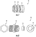
- FIGS. 7 and 8 show an exemplary embodiment of the bearing 10, including a roller bearing 11 having an outer ring disposed within a threaded fitting 13.
- a threaded cap 15 can be threadably engaged with a first end of the threaded fitting to fix the roller bearing 11 within the threaded fitting 13.
- the threaded cap 15 can include an opening 17 through which the rotating conduit portion 6 may be disposed.
- a nut 19 can be threadably engaged with a second end of the threaded fitting 13.
- the nut 19 and threaded fitting 13 can sandwich a horizontal surface 5 (see FIG. 5 ) of the dome portion 4 therebetween to fix the bearing 10 to the dome portion 4.
- An inner ring of the roller bearing 11 can be fixed to the rotating conduit potion 6. Providing a freely rotating bearing 10 can be important since any additional drag in the feeding system can cause other unrelated problems.
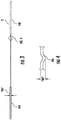
- the rotating conduit portion 6 may have a first end 24 disposed within the dome portion 4 and a second end 26 disposed above the dome portion 4. As can be seen in FIGS. 9 and 10 , the first end 24 may be positioned adjacent to the wire stack "WS" to admit wire "W” from the stack into the rotating conduit portion 6.
- the second end 26 of the rotating conduit portion 6 may be oriented substantially vertically (i.e., perpendicular to the first and second central axes (A-A, B-B) to enable the wire "W" to be routed out of the wire container.
- FIG. 10 shows the positioning of one of the ribs 16 atop the wire stack "WS" providing the aforementioned point contact with the individual wires of the stack.
- the rotating conduit portion 6 is a hollow tubular member made of nylon, with an outside diameter of 0.25 inches and an inside diameter of 0.125 inches. It will be appreciated that other materials and tube sizes can also be used as desired.
- the rotating conduit portion 6 can have a gentle multidimensional curvature configured to enable to the rotating conduit portion to pick up the wire off the stack.
- a gentle multidimensional curvature configured to enable to the rotating conduit portion to pick up the wire off the stack.
- the illustrated feed assist unit 1 can be made from a clear polymer material. It will be appreciated, however, that the material used to form the feed assist unit is not essential to its operation.
- the base portion 2 and dome portion 4 can be molded or otherwise formed as an integral piece. Alternatively, they can be formed as separate pieces that are adhered or otherwise fixed together.
- the disclosed feed assist unit 1 can be used with any of a variety of wire types, a non-limiting exemplary list of which includes aluminum, copper, stainless steel, silicon-bronze and steel.
Landscapes
- Engineering & Computer Science (AREA)
- Physics & Mathematics (AREA)
- Plasma & Fusion (AREA)
- Mechanical Engineering (AREA)
- Unwinding Of Filamentary Materials (AREA)
- Guides For Winding Or Rewinding, Or Guides For Filamentary Materials (AREA)
- Packaging Of Annular Or Rod-Shaped Articles, Wearing Apparel, Cassettes, Or The Like (AREA)
- Coiling Of Filamentary Materials In General (AREA)
Applications Claiming Priority (3)
| Application Number | Priority Date | Filing Date | Title |
|---|---|---|---|
| US201462033742P | 2014-08-06 | 2014-08-06 | |
| EP15748416.3A EP2996978B1 (de) | 2014-08-06 | 2015-07-30 | Schwimmende zuführungsunterstützungseinheit zur ausgabe von in grossmengen verpacktem schweissdraht |
| PCT/US2015/042910 WO2016022389A1 (en) | 2014-08-06 | 2015-07-30 | Floating feed assist unit for the payoff of bulk packaged welding wire |
Related Parent Applications (2)
| Application Number | Title | Priority Date | Filing Date |
|---|---|---|---|
| EP15748416.3A Division EP2996978B1 (de) | 2014-08-06 | 2015-07-30 | Schwimmende zuführungsunterstützungseinheit zur ausgabe von in grossmengen verpacktem schweissdraht |
| EP15748416.3A Division-Into EP2996978B1 (de) | 2014-08-06 | 2015-07-30 | Schwimmende zuführungsunterstützungseinheit zur ausgabe von in grossmengen verpacktem schweissdraht |
Publications (1)
| Publication Number | Publication Date |
|---|---|
| EP3409624A1 true EP3409624A1 (de) | 2018-12-05 |
Family
ID=53801232
Family Applications (2)
| Application Number | Title | Priority Date | Filing Date |
|---|---|---|---|
| EP18184506.6A Withdrawn EP3409624A1 (de) | 2014-08-06 | 2015-07-30 | Schwimmende zuführungsunterstützungseinheit zur ausgabe von in grossmengen verpacktem schweissdraht |
| EP15748416.3A Active EP2996978B1 (de) | 2014-08-06 | 2015-07-30 | Schwimmende zuführungsunterstützungseinheit zur ausgabe von in grossmengen verpacktem schweissdraht |
Family Applications After (1)
| Application Number | Title | Priority Date | Filing Date |
|---|---|---|---|
| EP15748416.3A Active EP2996978B1 (de) | 2014-08-06 | 2015-07-30 | Schwimmende zuführungsunterstützungseinheit zur ausgabe von in grossmengen verpacktem schweissdraht |
Country Status (10)
| Country | Link |
|---|---|
| US (2) | US10059561B2 (de) |
| EP (2) | EP3409624A1 (de) |
| JP (1) | JP2017529241A (de) |
| KR (1) | KR20170030598A (de) |
| CN (1) | CN106660734A (de) |
| ES (1) | ES2696835T3 (de) |
| MX (1) | MX2017001676A (de) |
| PL (1) | PL2996978T3 (de) |
| TW (1) | TWI639481B (de) |
| WO (1) | WO2016022389A1 (de) |
Families Citing this family (5)
| Publication number | Priority date | Publication date | Assignee | Title |
|---|---|---|---|---|
| PL2996978T3 (pl) * | 2014-08-06 | 2019-01-31 | Alcotec Wire Corporation | Zmiennopozycyjny zespół wspomagający podawanie do odwijania luźno nawiniętego drutu spawalniczego |
| DE102017103792A1 (de) | 2017-02-23 | 2018-08-23 | R & L Furthmayr Gmbh | Vorrichtung und Verfahren zum Entnehmen und Fördern von Drähten |
| US11174121B2 (en) | 2020-01-20 | 2021-11-16 | Awds Technologies Srl | Device for imparting a torsional force onto a wire |
| US11278981B2 (en) * | 2020-01-20 | 2022-03-22 | Awds Technologies Srl | Device for imparting a torsional force onto a wire |
| JP1684294S (de) * | 2020-09-08 | 2021-04-26 |
Citations (7)
| Publication number | Priority date | Publication date | Assignee | Title |
|---|---|---|---|---|
| JPS61157567U (de) * | 1985-03-20 | 1986-09-30 | ||
| JP2005053649A (ja) * | 2003-08-05 | 2005-03-03 | Nippon Steel & Sumikin Welding Co Ltd | 溶接用ワイヤの装填物 |
| EP1698421A2 (de) * | 2005-03-04 | 2006-09-06 | SIDERGAS Spa | Rückhalter für einen Schweissdrahtbehälter |
| JP2007238323A (ja) * | 2006-03-13 | 2007-09-20 | Komatsu Ltd | 線材ガイド治具 |
| WO2007149689A2 (en) * | 2006-06-16 | 2007-12-27 | Lincoln Global, Inc. | Guide ring for coiled wire |
| DE202011108769U1 (de) * | 2011-12-07 | 2012-01-24 | Mig Weld Gmbh International | Abspuleinrichtung für Drahtfässer |
| US20130119184A1 (en) * | 2011-11-16 | 2013-05-16 | Illinois Tool Works Inc. | Floating dispensing mechanism for drum packed welding wire |
Family Cites Families (28)
| Publication number | Priority date | Publication date | Assignee | Title |
|---|---|---|---|---|
| US1804996A (en) | 1928-03-23 | 1931-05-12 | Bay State Fishing Company | Wire support and guide |
| US2319828A (en) | 1941-07-11 | 1943-05-25 | United Shoe Machinery Corp | Wire uncoiling apparatus |
| FR2071007A5 (de) | 1969-12-15 | 1971-09-17 | Commercy Trefileries Ate | |
| US3618873A (en) | 1970-05-21 | 1971-11-09 | United States Steel Corp | Spinner-type wire uncoiling apparatus |
| US3815844A (en) | 1972-03-20 | 1974-06-11 | Portland Chain Mfg Co | Method and apparatus for unwinding coiled material |
| JPS5530313A (en) | 1978-08-21 | 1980-03-04 | Osaka Denki Kk | Take out device for pack wound wire for welding |
| US4253624A (en) | 1980-04-07 | 1981-03-03 | Colbert Robert E | Welding wire dispenser |
| JPS61157567A (ja) * | 1984-12-28 | 1986-07-17 | Daicel Chem Ind Ltd | 合板用接着剤 |
| US4657204A (en) | 1986-02-14 | 1987-04-14 | Colbert Robert E | Welding wire dispenser |
| US5911381A (en) | 1994-05-11 | 1999-06-15 | Plumettaz As | Stocking device for coilable elements and method of use |
| US5634604A (en) | 1995-03-09 | 1997-06-03 | Elco Enterprises, Inc. | Wire dispenser with base anti-rotation lock |
| US5657935A (en) | 1995-12-07 | 1997-08-19 | Elco Enterprises, Inc. | Wire dispenser with adjustable base |
| JPH09315686A (ja) | 1996-05-22 | 1997-12-09 | Nippon Steel Weld Prod & Eng Co Ltd | 溶接用ワイヤの装填物 |
| JP3820292B2 (ja) * | 1996-11-07 | 2006-09-13 | ミサワホーム株式会社 | 建物ユニット用連結具 |
| US6242711B1 (en) | 1999-12-27 | 2001-06-05 | Accudata, Inc. | Arc welding monitoring system |
| US6286748B1 (en) | 1999-12-27 | 2001-09-11 | Elco Enterprises, Inc. | Welding wire feeder |
| JP2001355209A (ja) * | 2000-06-13 | 2001-12-26 | Kyobashi Kogyo Kk | コンクリート高欄の補修工法 |
| US6484964B1 (en) | 2000-08-17 | 2002-11-26 | Elco Enterprises, Inc. | Welding wire dereeler |
| US6827217B2 (en) * | 2001-07-11 | 2004-12-07 | Kabushiki Kaisha Kobe Seiko Sho | Welding wire container |
| DE10162189A1 (de) * | 2001-12-18 | 2003-07-17 | Kuesters Eduard Maschf | Temperierbare Walze |
| US6547176B1 (en) | 2002-06-04 | 2003-04-15 | Air Liquide Canada Inc. | Wire unwinding controller |
| US7100863B2 (en) | 2003-12-16 | 2006-09-05 | Lincoln Global, Inc. | Floating liner |
| WO2008085761A1 (en) | 2007-01-03 | 2008-07-17 | Elco Enterprises, Inc. | Wire dispensing system |
| KR100853530B1 (ko) | 2007-07-06 | 2008-08-21 | 고려용접봉 주식회사 | 용접 와이어용 페일팩 |
| CA2741639C (en) | 2008-10-28 | 2015-12-15 | Edward L. Cooper | Conduit |
| US8985495B2 (en) | 2010-07-09 | 2015-03-24 | Hyundai Welding Co., Ltd. | Device for preventing entanglement of welding wire |
| JP5530313B2 (ja) | 2010-09-03 | 2014-06-25 | 京セラケミカル株式会社 | サーミスタセンサ注形用樹脂組成物及びサーミスタセンサ |
| PL2996978T3 (pl) * | 2014-08-06 | 2019-01-31 | Alcotec Wire Corporation | Zmiennopozycyjny zespół wspomagający podawanie do odwijania luźno nawiniętego drutu spawalniczego |
-
2015
- 2015-07-30 PL PL15748416T patent/PL2996978T3/pl unknown
- 2015-07-30 WO PCT/US2015/042910 patent/WO2016022389A1/en not_active Ceased
- 2015-07-30 KR KR1020177003655A patent/KR20170030598A/ko not_active Ceased
- 2015-07-30 JP JP2017506686A patent/JP2017529241A/ja active Pending
- 2015-07-30 EP EP18184506.6A patent/EP3409624A1/de not_active Withdrawn
- 2015-07-30 MX MX2017001676A patent/MX2017001676A/es unknown
- 2015-07-30 CN CN201580043903.0A patent/CN106660734A/zh active Pending
- 2015-07-30 US US15/501,621 patent/US10059561B2/en active Active
- 2015-07-30 ES ES15748416T patent/ES2696835T3/es active Active
- 2015-07-30 EP EP15748416.3A patent/EP2996978B1/de active Active
- 2015-08-05 TW TW104125473A patent/TWI639481B/zh not_active IP Right Cessation
-
2018
- 2018-07-31 US US16/049,876 patent/US20190062099A1/en not_active Abandoned
Patent Citations (7)
| Publication number | Priority date | Publication date | Assignee | Title |
|---|---|---|---|---|
| JPS61157567U (de) * | 1985-03-20 | 1986-09-30 | ||
| JP2005053649A (ja) * | 2003-08-05 | 2005-03-03 | Nippon Steel & Sumikin Welding Co Ltd | 溶接用ワイヤの装填物 |
| EP1698421A2 (de) * | 2005-03-04 | 2006-09-06 | SIDERGAS Spa | Rückhalter für einen Schweissdrahtbehälter |
| JP2007238323A (ja) * | 2006-03-13 | 2007-09-20 | Komatsu Ltd | 線材ガイド治具 |
| WO2007149689A2 (en) * | 2006-06-16 | 2007-12-27 | Lincoln Global, Inc. | Guide ring for coiled wire |
| US20130119184A1 (en) * | 2011-11-16 | 2013-05-16 | Illinois Tool Works Inc. | Floating dispensing mechanism for drum packed welding wire |
| DE202011108769U1 (de) * | 2011-12-07 | 2012-01-24 | Mig Weld Gmbh International | Abspuleinrichtung für Drahtfässer |
Also Published As
| Publication number | Publication date |
|---|---|
| PL2996978T3 (pl) | 2019-01-31 |
| US20190062099A1 (en) | 2019-02-28 |
| ES2696835T3 (es) | 2019-01-18 |
| JP2017529241A (ja) | 2017-10-05 |
| TW201609300A (zh) | 2016-03-16 |
| US20170233216A1 (en) | 2017-08-17 |
| CN106660734A (zh) | 2017-05-10 |
| EP2996978A1 (de) | 2016-03-23 |
| US10059561B2 (en) | 2018-08-28 |
| EP2996978B1 (de) | 2018-09-12 |
| KR20170030598A (ko) | 2017-03-17 |
| MX2017001676A (es) | 2017-05-09 |
| TWI639481B (zh) | 2018-11-01 |
| WO2016022389A1 (en) | 2016-02-11 |
Similar Documents
| Publication | Publication Date | Title |
|---|---|---|
| US20190062099A1 (en) | Floating feed assist unit for the payoff of bulk packaged welding wire | |
| US8936210B2 (en) | Floating dispensing mechanism for drum packed welding wire | |
| EP2176025B1 (de) | Schweissdrahtführungsring mit abgeschrägter oberfläche | |
| US7721985B2 (en) | Welding wire guide ring | |
| US5758834A (en) | Welding wire storage and shipping container | |
| EP2035312B1 (de) | Führungsring für wickeldraht | |
| US3593943A (en) | Electric wire dispensing apparatus | |
| EP2168706A1 (de) | Halter für einen Schweißdrahtbehälter mit flexiblen Klappen; Kombination von Schweissdrahtbund und einem solchen Halter | |
| US6547176B1 (en) | Wire unwinding controller | |
| US9260269B2 (en) | Wire retaining ring for a welding system | |
| EP2256064A1 (de) | Behälter für Schweißdraht mit verlängerten Elementen zum Halten der Drahtspule | |
| US4471921A (en) | Reel wire dispenser | |
| US2319828A (en) | Wire uncoiling apparatus | |
| RU2492978C2 (ru) | Дозатор упакованной проволоки | |
| US20030230660A1 (en) | Decoiling apparatus and methods for unwinding coiled material | |
| KR20190118665A (ko) | 디-코일링 콘 | |
| JPH0347738Y2 (de) | ||
| US554226A (en) | white | |
| JPS6124537Y2 (de) | ||
| JPH0520749Y2 (de) | ||
| JPH0663547U (ja) | 線材供給装置 | |
| JP2007153613A (ja) | 電設作業工具合成樹脂製電線管リール |
Legal Events
| Date | Code | Title | Description |
|---|---|---|---|
| PUAI | Public reference made under article 153(3) epc to a published international application that has entered the european phase |
Free format text: ORIGINAL CODE: 0009012 |
|
| STAA | Information on the status of an ep patent application or granted ep patent |
Free format text: STATUS: THE APPLICATION HAS BEEN PUBLISHED |
|
| AC | Divisional application: reference to earlier application |
Ref document number: 2996978 Country of ref document: EP Kind code of ref document: P |
|
| AK | Designated contracting states |
Kind code of ref document: A1 Designated state(s): AL AT BE BG CH CY CZ DE DK EE ES FI FR GB GR HR HU IE IS IT LI LT LU LV MC MK MT NL NO PL PT RO RS SE SI SK SM TR |
|
| RIN1 | Information on inventor provided before grant (corrected) |
Inventor name: PFALLER, THOMAS Inventor name: KRAUSE, ROBERT |
|
| STAA | Information on the status of an ep patent application or granted ep patent |
Free format text: STATUS: REQUEST FOR EXAMINATION WAS MADE |
|
| 17P | Request for examination filed |
Effective date: 20190529 |
|
| RBV | Designated contracting states (corrected) |
Designated state(s): AL AT BE BG CH CY CZ DE DK EE ES FI FR GB GR HR HU IE IS IT LI LT LU LV MC MK MT NL NO PL PT RO RS SE SI SK SM TR |
|
| STAA | Information on the status of an ep patent application or granted ep patent |
Free format text: STATUS: EXAMINATION IS IN PROGRESS |
|
| 17Q | First examination report despatched |
Effective date: 20191217 |
|
| STAA | Information on the status of an ep patent application or granted ep patent |
Free format text: STATUS: THE APPLICATION IS DEEMED TO BE WITHDRAWN |
|
| 18D | Application deemed to be withdrawn |
Effective date: 20200603 |