EP3409943B1 - Pompe à piston et utilisation d'une pompe à piston - Google Patents
Pompe à piston et utilisation d'une pompe à piston Download PDFInfo
- Publication number
- EP3409943B1 EP3409943B1 EP18173921.0A EP18173921A EP3409943B1 EP 3409943 B1 EP3409943 B1 EP 3409943B1 EP 18173921 A EP18173921 A EP 18173921A EP 3409943 B1 EP3409943 B1 EP 3409943B1
- Authority
- EP
- European Patent Office
- Prior art keywords
- chamber
- plunger
- plunger pump
- pump according
- pressure
- Prior art date
- Legal status (The legal status is an assumption and is not a legal conclusion. Google has not performed a legal analysis and makes no representation as to the accuracy of the status listed.)
- Active
Links
Images
Classifications
-
- F—MECHANICAL ENGINEERING; LIGHTING; HEATING; WEAPONS; BLASTING
- F04—POSITIVE - DISPLACEMENT MACHINES FOR LIQUIDS; PUMPS FOR LIQUIDS OR ELASTIC FLUIDS
- F04B—POSITIVE-DISPLACEMENT MACHINES FOR LIQUIDS; PUMPS
- F04B1/00—Multi-cylinder machines or pumps characterised by number or arrangement of cylinders
- F04B1/04—Multi-cylinder machines or pumps characterised by number or arrangement of cylinders having cylinders in star- or fan-arrangement
- F04B1/0404—Details or component parts
- F04B1/0408—Pistons
-
- A—HUMAN NECESSITIES
- A01—AGRICULTURE; FORESTRY; ANIMAL HUSBANDRY; HUNTING; TRAPPING; FISHING
- A01J—MANUFACTURE OF DAIRY PRODUCTS
- A01J11/00—Apparatus for treating milk
- A01J11/16—Homogenising milk
-
- F—MECHANICAL ENGINEERING; LIGHTING; HEATING; WEAPONS; BLASTING
- F04—POSITIVE - DISPLACEMENT MACHINES FOR LIQUIDS; PUMPS FOR LIQUIDS OR ELASTIC FLUIDS
- F04B—POSITIVE-DISPLACEMENT MACHINES FOR LIQUIDS; PUMPS
- F04B1/00—Multi-cylinder machines or pumps characterised by number or arrangement of cylinders
- F04B1/04—Multi-cylinder machines or pumps characterised by number or arrangement of cylinders having cylinders in star- or fan-arrangement
- F04B1/0404—Details or component parts
- F04B1/0448—Sealing means, e.g. for shafts or housings
-
- F—MECHANICAL ENGINEERING; LIGHTING; HEATING; WEAPONS; BLASTING
- F04—POSITIVE - DISPLACEMENT MACHINES FOR LIQUIDS; PUMPS FOR LIQUIDS OR ELASTIC FLUIDS
- F04B—POSITIVE-DISPLACEMENT MACHINES FOR LIQUIDS; PUMPS
- F04B15/00—Pumps adapted to handle specific fluids, e.g. by selection of specific materials for pumps or pump parts
-
- F—MECHANICAL ENGINEERING; LIGHTING; HEATING; WEAPONS; BLASTING
- F04—POSITIVE - DISPLACEMENT MACHINES FOR LIQUIDS; PUMPS FOR LIQUIDS OR ELASTIC FLUIDS
- F04B—POSITIVE-DISPLACEMENT MACHINES FOR LIQUIDS; PUMPS
- F04B53/00—Component parts, details or accessories not provided for in, or of interest apart from, groups F04B1/00 - F04B23/00 or F04B39/00 - F04B47/00
- F04B53/14—Pistons, piston-rods or piston-rod connections
- F04B53/143—Sealing provided on the piston
-
- F—MECHANICAL ENGINEERING; LIGHTING; HEATING; WEAPONS; BLASTING
- F16—ENGINEERING ELEMENTS AND UNITS; GENERAL MEASURES FOR PRODUCING AND MAINTAINING EFFECTIVE FUNCTIONING OF MACHINES OR INSTALLATIONS; THERMAL INSULATION IN GENERAL
- F16J—PISTONS; CYLINDERS; SEALINGS
- F16J15/00—Sealings
- F16J15/50—Sealings between relatively-movable members, by means of a sealing without relatively-moving surfaces, e.g. fluid-tight sealings for transmitting motion through a wall
- F16J15/52—Sealings between relatively-movable members, by means of a sealing without relatively-moving surfaces, e.g. fluid-tight sealings for transmitting motion through a wall by means of sealing bellows or diaphragms
-
- F—MECHANICAL ENGINEERING; LIGHTING; HEATING; WEAPONS; BLASTING
- F04—POSITIVE - DISPLACEMENT MACHINES FOR LIQUIDS; PUMPS FOR LIQUIDS OR ELASTIC FLUIDS
- F04B—POSITIVE-DISPLACEMENT MACHINES FOR LIQUIDS; PUMPS
- F04B2205/00—Fluid parameters
- F04B2205/02—Pressure in the inlet chamber
-
- F—MECHANICAL ENGINEERING; LIGHTING; HEATING; WEAPONS; BLASTING
- F04—POSITIVE - DISPLACEMENT MACHINES FOR LIQUIDS; PUMPS FOR LIQUIDS OR ELASTIC FLUIDS
- F04B—POSITIVE-DISPLACEMENT MACHINES FOR LIQUIDS; PUMPS
- F04B2205/00—Fluid parameters
- F04B2205/50—Presence of foreign matter in the fluid
Definitions
- the invention relates to a plunger pump according to the preamble of claim 1 and the use of a plunger pump.
- plunger pumps are well known.
- An example is the EP 1 260 712 B1 referenced, in which several, ie specifically three, plungers can be driven by means of a transmission, the plungers being offset by 120 ° on a crankshaft.
- This plunger arrangement compensates for dynamic forces and, in particular, reduces flow pulsation.
- a bellows partially enveloping the plunger is provided, which is attached on the one hand to the plunger and on the other hand to a boundary wall.
- the plunger On the pressure side, the plunger is guided in a non-contact sealing arrangement that separates a suction chamber from a pressure chamber, a suction valve and a pressure valve being assigned to a pump head.
- the has from EP 1 260 712 B1 well-known plunger pump proven.
- Plunger pumps are also used for certain areas of application, in particular for the homogenization of liquid foods, for example milk, the plunger of which is guided in a contacting sealing arrangement.
- Such a plunger pump is in the EP 2 941 567 B1 disclosed.
- the operation of this plunger pump for the use mentioned turns out to be unsatisfactory and, above all, does not meet the hygienic and aseptic requirements.
- the contacting seal consisting of at least one sealing ring on the plunger made of a relatively soft sealing material
- abrasion particles that get into the suction space and thus into the milk to be homogenized are released. This contamination is not acceptable from a hygienic point of view and ultimately leads to the fluid not being able to be used widely.
- the plunger pump is designed in such a way that the plunger reaches a septic area during each suction stroke, whereby germs can accumulate on the surface of the plunger, which come into contact with the fluid during the subsequent pressure stroke, so that the danger also arises from this that the milk is contaminated in an unacceptable manner.
- steam or hot condensate is applied to the corresponding area during the entire production period, but this is only possible with a correspondingly high and cost-intensive outlay.
- a plunger pump which differs from the genus and which does not have a contactless sealing arrangement in which the plunger can be guided is from the US 2013/0039788 A1 known.
- a bellows partially enveloping the plunger is under atmospheric pressure in its interior and is openly connected to a chamber which, on the one hand, absorbs the excess air volume when the bellows is compressed with a corresponding stroke movement of the plunger and, on the other hand, a fluid entering from a suction chamber in the event of a leak.
- the invention has for its object to develop a plunger pump of the generic type so that its usability is improved.
- the plunger pump according to the invention can now be used wherever there are special hygienic requirements for the conveyance of a fluid or when environmentally problematic substances are conveyed. In this case, the new design of the plunger pump prevents these substances from getting into the environment.
- the decisive advantage of the plunger pump according to the invention is that the area of the plunger, which is functionally related to the environment lies outside the fluid to be pumped and can therefore be contaminated, is hermetically sealed from the fluid to be pumped in the suction chamber by means of bellows.
- Such a plunger pump is thus ideally used in a homogenization device.
- the plunger pump according to the invention is characterized by a long service life of the sealing elements, which experience has shown to be> 8000 operating hours.
- the performance adjustment of the plunger pump has to be adapted to the specific application, especially with regard to the stroke frequency, i.e. the speed of the crankshaft.
- the non-contact sealing arrangement has a guide sleeve made of an approved corrosion-resistant hard metal.
- the other functional parts, insofar as they come into contact with the fluid, are preferably made of stainless steel.
- the plunger pump according to the invention is further characterized by its compact design, with a large stroke volume, which results in a minimization of the manufacturing costs, for example compared to a diaphragm pump.
- the compensation chamber is sealed off from a drive space in which the transmission is arranged, forming an intermediate space between the compensation chamber and the transmission space.
- the intermediate space itself in turn can also be sealed off from the transmission space by a bellows which is fastened on the one hand to the plunger and on the other hand to a boundary wall of the transmission space, so that there is an overall triple seal between the transmission space and the suction chamber, which prevents contamination of the fluid in the suction chamber by lubricants in the gear chamber.
- the pressure of the medium in the compensation chamber is equal to or less than the fluid pressure in the suction chamber.
- the pressure prevailing in the compensation chamber is 0.05-0.2 bar, preferably 0.1 bar, less than the inlet pressure of the fluid.
- the fluid is guided into the compensation chamber due to the higher pressure, so that the medium therein, preferably an inert gas, for example N 2 , does not reach the suction chamber, the compensation chamber in the Area of the implementation of the plunger is sealed with a lip seal to the space under ambient pressure.
- the medium therein preferably an inert gas, for example N 2
- the bellows assigned to the suction chamber consists of a thermoplastic material, for example PTFE, or an elastomer material, which is characterized by a special load capacity, in particular a long service life.
- Functional monitoring of the bellows can be carried out by means of a control circuit for monitoring and setting the differential pressure between the compensation chamber and the suction chamber.
- a further monitoring in the area of the compensation chamber adjacent to the intermediate space detects a penetration of the fluid.
- the monitoring can take place via the detection of the pH value, the conductivity, the level, the turbidity or the like, whereby several corresponding sensors can be installed and active in parallel.
- a pump head is assigned to suction and pressure valves, to which, when the plunger pump is used in a homogenizing device, a homogenizing valve is connected, in which the pressurized fluid is released for homogenization.
- the gap seal in particular can be cleaned by means of forced rinsing, in that the adjustable homogenizing valve generates a cleaning fluid at a higher pressure (50-100 bar) than is possible according to the prior art (5-6 bar).
- the homogenizing valve can act like a CIP pump (cleaning in place) without increasing drive power by increasing the speed of the crankshaft.
- the resulting volume flow corresponds to that of a CIP pump, however, with a lower drive power than this, due to the better efficiency.
- the spaces between the bellows are subject to a self-cleaning effect due to radial, oscillating displacement of volume during the lifting movement and a low tendency to stick to the surface of the bellows, which is preferably made of a PTFE material.
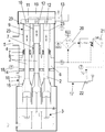
- the single figure shows a plunger pump in a schematic sectional view.
- a plunger pump can be seen, with a housing 1, which has a gear space 3 for receiving a gear, an adjoining space 16, a compensation chamber 6 and a suction space 4.
- a supply line 5 is connected to the latter, via which a fluid under additional pressure can be supplied, in the example a fluid to be homogenized, in particular milk.
- Three plungers 2 are connected to a crankshaft of the transmission (not shown in more detail), namely at an angular offset of 120 °, the plungers 2 being moved in an oscillating manner during operation.
- the plungers 2 can be constructed in several parts.
- plunger 2 For the sake of simplicity, only one plunger 2 is referred to below, since the other plungers are identical in construction and function.
- the plunger 2 is axially displaceably mounted with a head in a guide sleeve 23 of a sealing arrangement 9, which is designed such that a non-contact seal, that is to say a gap seal, results between the plunger 2 and the guide sleeve 23, as is known from the prior art is.
- a working chamber 12 is coaxially assigned to a suction valve 10 and a pressure valve 11, specifically in the area of a pump head 19 closing the housing 1, to which a homogenizing valve 13 corresponding to the pressure valve 11 is connected.
- a bellows 7 on the suction chamber side encloses a partial area of the plunger 2 in the suction chamber 4 and is fastened on the one hand in a sealing manner to the plunger 2 and on the other hand in a sealing manner on a boundary wall 8 which separates the suction chamber 4 from the compensation chamber 6.
- the bellows 7 on the suction space side covers a passage opening of the boundary wall 8 through which the plunger 2 is guided.
- the compensation chamber 6 is filled with a medium, under a pressure which is equal to or less than the fluid pressure in the suction chamber 4, preferably 0.1 bar lower.
- an inert gas is used as the medium, which otherwise causes a counterpressure in the bellows 7 on the suction chamber side to the fluid pressure in the suction chamber 4 which is present on the outside of the bellows 7 on the suction chamber side.
- the space 16 is sealed in the area of the plungers 2 carried out via lip seals 14 with respect to the compensating chamber 6 and with respect to the gear space 3 by a bellows 15 on the space side, so that a redundant triple seal to the gear space 3 is provided to the suction space 4, which effectively prevents that for example, transmission oil gets into the suction chamber 4.
- a leakage detection 18 is provided in the compensation chamber 6, for example a sensor, by means of which a penetration of fluid from the suction chamber 4 through a defective bellows 7 into the compensation chamber 6 can be detected.
- This leakage detection 18 can be carried out by determining a pH value, the conductivity, the fill level, the turbidity or the like. It is also conceivable to arrange several sensors that can be active in parallel.
- a control device 17 which has a differential pressure monitor 20, a controller 21 and a pressure control valve 22 with position monitoring, is connected to the suction chamber 4 on the one hand and to the compensation chamber 6 on the other.
Landscapes
- Engineering & Computer Science (AREA)
- General Engineering & Computer Science (AREA)
- Mechanical Engineering (AREA)
- Life Sciences & Earth Sciences (AREA)
- Animal Husbandry (AREA)
- Environmental Sciences (AREA)
- Details Of Reciprocating Pumps (AREA)
Claims (9)
- Pompe à piston plongeur pour le transport d'un fluide, comprenant au moins un piston plongeur (2) pouvant être entraîné en oscillation et guidé sans contact dans un agencement d'étanchéité (9) qui sépare une chambre d'aspiration (4) présentant une conduite d'alimentation (5) d'une chambre de travail (12), et comprenant un soufflet (7) entourant hermétiquement le piston plongeur (2) dans certaines zones, qui est fixé d'une part de manière étanche au piston plongeur (2) et d'autre part à une paroi de délimitation (8) dans la zone d'une ouverture de passage pour le piston plongeur (2), caractérisée en ce qu'au voisinage de la chambre d'aspiration (4) est disposée une chambre de compensation (6) ouverte vers l'intérieur du soufflet (7), qui est remplie d'un milieu sous pression pendant le fonctionnement, la pression du milieu étant égale ou inférieure à la pression d'arrivée du fluide agissant extérieurement sur le soufflet (7).
- Pompe à piston plongeur selon la revendication 1 ou 2, caractérisée en ce que la pression du milieu est inférieure de 0,05 à 0,2 bar, de préférence de 0,1 bar, à la pression d'arrivée du fluide régnant dans la chambre d'aspiration (4).
- Pompe à piston plongeur selon l'une des revendications précédentes, caractérisée en ce qu'un dispositif de régulation (17) relié à la chambre d'aspiration (4) et à la chambre de compensation (6) est prévu, avec lequel une surveillance différentielle des pressions dans la chambre d'aspiration (4) et la chambre de compensation (6) peut être effectuée.
- Pompe à piston plongeur selon l'une des revendications précédentes, caractérisée en ce qu'un moyen de détection de fuite (18), avec lequel des paramètres matériels variables du milieu peuvent être détectés, est en liaison fonctionnelle avec la chambre de compensation (6).
- Pompe à piston plongeur selon l'une des revendications précédentes, caractérisée en ce qu'entre une chambre de transmission (3) recevant un vilebrequin d'une transmission et la chambre de compensation (6), il est prévu une chambre intermédiaire (16) qui est étanche par rapport à la chambre de compensation (6) et à la chambre de transmission (3).
- Pompe à piston plongeur selon l'une des revendications précédentes, caractérisée en ce qu'à une tête de pompe (19) est raccordée une soupape d'homogénéisation (13) à laquelle sont associées une soupape d'aspiration (10) communiquant avec la chambre de travail (12) et une soupape de pression (11), laquelle soupape d'homogénéisation (13) communique avec la chambre de travail (12) par l'intermédiaire de la soupape de pression (11).
- Pompe à piston plongeur selon l'une des revendications précédentes, caractérisée en ce que plusieurs, de préférence trois pistons plongeurs (2) disposés à une même distance angulaire les uns des autres sont maintenus sur le vilebrequin.
- Pompe à piston plongeur selon l'une des revendications précédentes, caractérisée en ce que le milieu dans la chambre de compensation (6) est un gaz inerte.
- Utilisation de la pompe à piston plongeur selon la revendication 1 pour augmenter la pression d'un fluide dans un dispositif d'homogénéisation.
Priority Applications (1)
| Application Number | Priority Date | Filing Date | Title |
|---|---|---|---|
| PL18173921T PL3409943T3 (pl) | 2017-06-01 | 2018-05-23 | Pompa nurnikowa i zastosowanie pompy nurnikowej |
Applications Claiming Priority (1)
| Application Number | Priority Date | Filing Date | Title |
|---|---|---|---|
| DE102017112110.2A DE102017112110A1 (de) | 2017-06-01 | 2017-06-01 | Plungerpumpe sowie Verwendung einer Plungerpumpe |
Publications (2)
| Publication Number | Publication Date |
|---|---|
| EP3409943A1 EP3409943A1 (fr) | 2018-12-05 |
| EP3409943B1 true EP3409943B1 (fr) | 2020-08-05 |
Family
ID=62244349
Family Applications (1)
| Application Number | Title | Priority Date | Filing Date |
|---|---|---|---|
| EP18173921.0A Active EP3409943B1 (fr) | 2017-06-01 | 2018-05-23 | Pompe à piston et utilisation d'une pompe à piston |
Country Status (4)
| Country | Link |
|---|---|
| EP (1) | EP3409943B1 (fr) |
| DE (1) | DE102017112110A1 (fr) |
| ES (1) | ES2821406T3 (fr) |
| PL (1) | PL3409943T3 (fr) |
Families Citing this family (2)
| Publication number | Priority date | Publication date | Assignee | Title |
|---|---|---|---|---|
| DE102018120582A1 (de) * | 2018-08-23 | 2020-02-27 | Schwing Gmbh | Kolbenpumpe für Dickstoffe mit Wasserkasten |
| CN111677642B (zh) * | 2020-06-23 | 2025-08-22 | 追觅科技(上海)有限公司 | 一种摆动泵、具有其的自混合发泡装置及洗手机 |
Family Cites Families (6)
| Publication number | Priority date | Publication date | Assignee | Title |
|---|---|---|---|---|
| GB656498A (en) * | 1948-10-05 | 1951-08-22 | Jean Lavigne | Fluid compressors |
| US4556369A (en) * | 1982-08-13 | 1985-12-03 | Anton Braun | Bellows seal |
| DE10125669B4 (de) | 2001-05-25 | 2006-04-27 | Hammelmann Maschinenfabrik Gmbh | Pumpe, insbesondere Plungerpumpe |
| WO2011137143A1 (fr) * | 2010-04-30 | 2011-11-03 | Graco Minnesota Inc. | Chambre auxiliaire à soufflet |
| WO2014095897A1 (fr) | 2012-12-21 | 2014-06-26 | Tetra Laval Holdings & Finance S.A. | Piston et utilisation d'un tel piston |
| DE102014106520A1 (de) * | 2014-05-09 | 2015-11-12 | Hammelmann Maschinenfabrik Gmbh | Hochdruck-Plungerpumpe |
-
2017
- 2017-06-01 DE DE102017112110.2A patent/DE102017112110A1/de not_active Withdrawn
-
2018
- 2018-05-23 ES ES18173921T patent/ES2821406T3/es active Active
- 2018-05-23 PL PL18173921T patent/PL3409943T3/pl unknown
- 2018-05-23 EP EP18173921.0A patent/EP3409943B1/fr active Active
Non-Patent Citations (1)
| Title |
|---|
| None * |
Also Published As
| Publication number | Publication date |
|---|---|
| PL3409943T3 (pl) | 2020-12-14 |
| DE102017112110A1 (de) | 2018-12-06 |
| ES2821406T3 (es) | 2021-04-26 |
| EP3409943A1 (fr) | 2018-12-05 |
Similar Documents
| Publication | Publication Date | Title |
|---|---|---|
| EP3090196B1 (fr) | Soupape | |
| DE102013010926A1 (de) | Radialwellendichtung | |
| EP0789147A2 (fr) | Pompe haute-pression à plongeur, travaillant de préférence à des pressions supérieures à 2000 bars | |
| WO2015078487A1 (fr) | Pompe de dosage et d'alimentation pour des fluides chimiquement agressifs et/ou abrasifs | |
| EP3409943B1 (fr) | Pompe à piston et utilisation d'une pompe à piston | |
| EP2969895A1 (fr) | Distributeur rotatif de milieux pour machines de remplissage de contenants | |
| DE4019746C1 (fr) | ||
| EP3246568A1 (fr) | Système de pompe | |
| WO2000071913A1 (fr) | Dispositif d'etancheite pour un piston soumis a l'action d'un fluide sous pression dans un cylindre de travail | |
| EP2123359B1 (fr) | Dispositif de pipetage pour l'aspiration et la distribution d'un fluide de dosage | |
| EP2949930B1 (fr) | Piston pour une pompe de dosage | |
| DE19603070B4 (de) | Prozessventil, insbesondere für die sterile Verfahrenstechnik | |
| DE202008016113U1 (de) | Aseptisches Rückschlagventil, insbesondere Tellerrückschlagventil | |
| EP2730821A1 (fr) | Dispositif et procédé d'isolation étanche d'une pièce de machine par rapport à une deuxième pièce de machine | |
| WO2006005330A1 (fr) | Ensemble d'etancheite | |
| DE102005045937A1 (de) | Kolbenpumpe für eine Schlupfregelung aufweisende Fahrzeugbremsanlage | |
| EP1417430B1 (fr) | Vanne a membrane | |
| EP3441612A1 (fr) | Unité de pompe, dispositif de stockage équipé d'une telle unité de pompe et procédé de fonctionnement dudit dispositif de stockage | |
| EP1703185B1 (fr) | Soupape coaxiale | |
| DE29507638U1 (de) | Ventil | |
| DE102020121486B3 (de) | Druckmittelzylinder mit statischer Endlagendichtung | |
| DE102019201847A1 (de) | Hochdruckpumpe, Pumpenkolben und Verfahren zum Homogenisieren | |
| WO2016086911A1 (fr) | Dispositif de compensation de longueur | |
| WO2020114656A1 (fr) | Engin spécial de génie civil, notamment fraiseuse à rideau souterrain | |
| EP2307727A2 (fr) | Pompe à engrenages pompe à engrenages |
Legal Events
| Date | Code | Title | Description |
|---|---|---|---|
| PUAI | Public reference made under article 153(3) epc to a published international application that has entered the european phase |
Free format text: ORIGINAL CODE: 0009012 |
|
| STAA | Information on the status of an ep patent application or granted ep patent |
Free format text: STATUS: THE APPLICATION HAS BEEN PUBLISHED |
|
| AK | Designated contracting states |
Kind code of ref document: A1 Designated state(s): AL AT BE BG CH CY CZ DE DK EE ES FI FR GB GR HR HU IE IS IT LI LT LU LV MC MK MT NL NO PL PT RO RS SE SI SK SM TR |
|
| AX | Request for extension of the european patent |
Extension state: BA ME |
|
| STAA | Information on the status of an ep patent application or granted ep patent |
Free format text: STATUS: REQUEST FOR EXAMINATION WAS MADE |
|
| 17P | Request for examination filed |
Effective date: 20190604 |
|
| RBV | Designated contracting states (corrected) |
Designated state(s): AL AT BE BG CH CY CZ DE DK EE ES FI FR GB GR HR HU IE IS IT LI LT LU LV MC MK MT NL NO PL PT RO RS SE SI SK SM TR |
|
| REG | Reference to a national code |
Ref country code: DE Ref legal event code: R079 Ref document number: 502018002070 Country of ref document: DE Free format text: PREVIOUS MAIN CLASS: F04B0001040000 Ipc: F04B0001040800 |
|
| GRAP | Despatch of communication of intention to grant a patent |
Free format text: ORIGINAL CODE: EPIDOSNIGR1 |
|
| STAA | Information on the status of an ep patent application or granted ep patent |
Free format text: STATUS: GRANT OF PATENT IS INTENDED |
|
| RIC1 | Information provided on ipc code assigned before grant |
Ipc: F04B 1/0448 20200101ALI20200221BHEP Ipc: F16J 15/52 20060101ALI20200221BHEP Ipc: A01J 11/16 20060101ALI20200221BHEP Ipc: B01F 15/02 20060101ALI20200221BHEP Ipc: F04B 15/00 20060101ALI20200221BHEP Ipc: F04B 1/0408 20200101AFI20200221BHEP Ipc: F04B 53/14 20060101ALI20200221BHEP |
|
| INTG | Intention to grant announced |
Effective date: 20200323 |
|
| GRAS | Grant fee paid |
Free format text: ORIGINAL CODE: EPIDOSNIGR3 |
|
| GRAA | (expected) grant |
Free format text: ORIGINAL CODE: 0009210 |
|
| STAA | Information on the status of an ep patent application or granted ep patent |
Free format text: STATUS: THE PATENT HAS BEEN GRANTED |
|
| AK | Designated contracting states |
Kind code of ref document: B1 Designated state(s): AL AT BE BG CH CY CZ DE DK EE ES FI FR GB GR HR HU IE IS IT LI LT LU LV MC MK MT NL NO PL PT RO RS SE SI SK SM TR |
|
| REG | Reference to a national code |
Ref country code: GB Ref legal event code: FG4D Free format text: NOT ENGLISH |
|
| REG | Reference to a national code |
Ref country code: CH Ref legal event code: EP |
|
| REG | Reference to a national code |
Ref country code: AT Ref legal event code: REF Ref document number: 1299063 Country of ref document: AT Kind code of ref document: T Effective date: 20200815 |
|
| REG | Reference to a national code |
Ref country code: DE Ref legal event code: R096 Ref document number: 502018002070 Country of ref document: DE |
|
| REG | Reference to a national code |
Ref country code: IE Ref legal event code: FG4D Free format text: LANGUAGE OF EP DOCUMENT: GERMAN |
|
| REG | Reference to a national code |
Ref country code: CH Ref legal event code: NV Representative=s name: ISLER AND PEDRAZZINI AG, CH |
|
| REG | Reference to a national code |
Ref country code: NL Ref legal event code: FP |
|
| REG | Reference to a national code |
Ref country code: FI Ref legal event code: FGE |
|
| REG | Reference to a national code |
Ref country code: LT Ref legal event code: MG4D |
|
| REG | Reference to a national code |
Ref country code: NO Ref legal event code: T2 Effective date: 20200805 |
|
| PG25 | Lapsed in a contracting state [announced via postgrant information from national office to epo] |
Ref country code: SE Free format text: LAPSE BECAUSE OF FAILURE TO SUBMIT A TRANSLATION OF THE DESCRIPTION OR TO PAY THE FEE WITHIN THE PRESCRIBED TIME-LIMIT Effective date: 20200805 Ref country code: GR Free format text: LAPSE BECAUSE OF FAILURE TO SUBMIT A TRANSLATION OF THE DESCRIPTION OR TO PAY THE FEE WITHIN THE PRESCRIBED TIME-LIMIT Effective date: 20201106 Ref country code: LT Free format text: LAPSE BECAUSE OF FAILURE TO SUBMIT A TRANSLATION OF THE DESCRIPTION OR TO PAY THE FEE WITHIN THE PRESCRIBED TIME-LIMIT Effective date: 20200805 Ref country code: BG Free format text: LAPSE BECAUSE OF FAILURE TO SUBMIT A TRANSLATION OF THE DESCRIPTION OR TO PAY THE FEE WITHIN THE PRESCRIBED TIME-LIMIT Effective date: 20201105 Ref country code: PT Free format text: LAPSE BECAUSE OF FAILURE TO SUBMIT A TRANSLATION OF THE DESCRIPTION OR TO PAY THE FEE WITHIN THE PRESCRIBED TIME-LIMIT Effective date: 20201207 Ref country code: HR Free format text: LAPSE BECAUSE OF FAILURE TO SUBMIT A TRANSLATION OF THE DESCRIPTION OR TO PAY THE FEE WITHIN THE PRESCRIBED TIME-LIMIT Effective date: 20200805 |
|
| PG25 | Lapsed in a contracting state [announced via postgrant information from national office to epo] |
Ref country code: LV Free format text: LAPSE BECAUSE OF FAILURE TO SUBMIT A TRANSLATION OF THE DESCRIPTION OR TO PAY THE FEE WITHIN THE PRESCRIBED TIME-LIMIT Effective date: 20200805 Ref country code: RS Free format text: LAPSE BECAUSE OF FAILURE TO SUBMIT A TRANSLATION OF THE DESCRIPTION OR TO PAY THE FEE WITHIN THE PRESCRIBED TIME-LIMIT Effective date: 20200805 Ref country code: IS Free format text: LAPSE BECAUSE OF FAILURE TO SUBMIT A TRANSLATION OF THE DESCRIPTION OR TO PAY THE FEE WITHIN THE PRESCRIBED TIME-LIMIT Effective date: 20201205 |
|
| REG | Reference to a national code |
Ref country code: ES Ref legal event code: FG2A Ref document number: 2821406 Country of ref document: ES Kind code of ref document: T3 Effective date: 20210426 |
|
| PG25 | Lapsed in a contracting state [announced via postgrant information from national office to epo] |
Ref country code: RO Free format text: LAPSE BECAUSE OF FAILURE TO SUBMIT A TRANSLATION OF THE DESCRIPTION OR TO PAY THE FEE WITHIN THE PRESCRIBED TIME-LIMIT Effective date: 20200805 Ref country code: DK Free format text: LAPSE BECAUSE OF FAILURE TO SUBMIT A TRANSLATION OF THE DESCRIPTION OR TO PAY THE FEE WITHIN THE PRESCRIBED TIME-LIMIT Effective date: 20200805 Ref country code: CZ Free format text: LAPSE BECAUSE OF FAILURE TO SUBMIT A TRANSLATION OF THE DESCRIPTION OR TO PAY THE FEE WITHIN THE PRESCRIBED TIME-LIMIT Effective date: 20200805 Ref country code: EE Free format text: LAPSE BECAUSE OF FAILURE TO SUBMIT A TRANSLATION OF THE DESCRIPTION OR TO PAY THE FEE WITHIN THE PRESCRIBED TIME-LIMIT Effective date: 20200805 Ref country code: SM Free format text: LAPSE BECAUSE OF FAILURE TO SUBMIT A TRANSLATION OF THE DESCRIPTION OR TO PAY THE FEE WITHIN THE PRESCRIBED TIME-LIMIT Effective date: 20200805 |
|
| REG | Reference to a national code |
Ref country code: DE Ref legal event code: R097 Ref document number: 502018002070 Country of ref document: DE |
|
| PG25 | Lapsed in a contracting state [announced via postgrant information from national office to epo] |
Ref country code: AL Free format text: LAPSE BECAUSE OF FAILURE TO SUBMIT A TRANSLATION OF THE DESCRIPTION OR TO PAY THE FEE WITHIN THE PRESCRIBED TIME-LIMIT Effective date: 20200805 |
|
| PLBE | No opposition filed within time limit |
Free format text: ORIGINAL CODE: 0009261 |
|
| STAA | Information on the status of an ep patent application or granted ep patent |
Free format text: STATUS: NO OPPOSITION FILED WITHIN TIME LIMIT |
|
| PG25 | Lapsed in a contracting state [announced via postgrant information from national office to epo] |
Ref country code: SK Free format text: LAPSE BECAUSE OF FAILURE TO SUBMIT A TRANSLATION OF THE DESCRIPTION OR TO PAY THE FEE WITHIN THE PRESCRIBED TIME-LIMIT Effective date: 20200805 |
|
| 26N | No opposition filed |
Effective date: 20210507 |
|
| PG25 | Lapsed in a contracting state [announced via postgrant information from national office to epo] |
Ref country code: SI Free format text: LAPSE BECAUSE OF FAILURE TO SUBMIT A TRANSLATION OF THE DESCRIPTION OR TO PAY THE FEE WITHIN THE PRESCRIBED TIME-LIMIT Effective date: 20200805 |
|
| PG25 | Lapsed in a contracting state [announced via postgrant information from national office to epo] |
Ref country code: MC Free format text: LAPSE BECAUSE OF FAILURE TO SUBMIT A TRANSLATION OF THE DESCRIPTION OR TO PAY THE FEE WITHIN THE PRESCRIBED TIME-LIMIT Effective date: 20200805 Ref country code: LU Free format text: LAPSE BECAUSE OF NON-PAYMENT OF DUE FEES Effective date: 20210523 |
|
| REG | Reference to a national code |
Ref country code: BE Ref legal event code: MM Effective date: 20210531 |
|
| PG25 | Lapsed in a contracting state [announced via postgrant information from national office to epo] |
Ref country code: IE Free format text: LAPSE BECAUSE OF NON-PAYMENT OF DUE FEES Effective date: 20210523 |
|
| PG25 | Lapsed in a contracting state [announced via postgrant information from national office to epo] |
Ref country code: BE Free format text: LAPSE BECAUSE OF NON-PAYMENT OF DUE FEES Effective date: 20210531 |
|
| PG25 | Lapsed in a contracting state [announced via postgrant information from national office to epo] |
Ref country code: CY Free format text: LAPSE BECAUSE OF FAILURE TO SUBMIT A TRANSLATION OF THE DESCRIPTION OR TO PAY THE FEE WITHIN THE PRESCRIBED TIME-LIMIT Effective date: 20200805 |
|
| PG25 | Lapsed in a contracting state [announced via postgrant information from national office to epo] |
Ref country code: HU Free format text: LAPSE BECAUSE OF FAILURE TO SUBMIT A TRANSLATION OF THE DESCRIPTION OR TO PAY THE FEE WITHIN THE PRESCRIBED TIME-LIMIT; INVALID AB INITIO Effective date: 20180523 |
|
| PG25 | Lapsed in a contracting state [announced via postgrant information from national office to epo] |
Ref country code: MK Free format text: LAPSE BECAUSE OF FAILURE TO SUBMIT A TRANSLATION OF THE DESCRIPTION OR TO PAY THE FEE WITHIN THE PRESCRIBED TIME-LIMIT Effective date: 20200805 |
|
| PG25 | Lapsed in a contracting state [announced via postgrant information from national office to epo] |
Ref country code: MT Free format text: LAPSE BECAUSE OF FAILURE TO SUBMIT A TRANSLATION OF THE DESCRIPTION OR TO PAY THE FEE WITHIN THE PRESCRIBED TIME-LIMIT Effective date: 20200805 |
|
| PGFP | Annual fee paid to national office [announced via postgrant information from national office to epo] |
Ref country code: NL Payment date: 20250317 Year of fee payment: 8 |
|
| PGFP | Annual fee paid to national office [announced via postgrant information from national office to epo] |
Ref country code: FI Payment date: 20250520 Year of fee payment: 8 |
|
| PGFP | Annual fee paid to national office [announced via postgrant information from national office to epo] |
Ref country code: DE Payment date: 20250414 Year of fee payment: 8 |
|
| PGFP | Annual fee paid to national office [announced via postgrant information from national office to epo] |
Ref country code: GB Payment date: 20250415 Year of fee payment: 8 Ref country code: ES Payment date: 20250616 Year of fee payment: 8 |
|
| PGFP | Annual fee paid to national office [announced via postgrant information from national office to epo] |
Ref country code: IT Payment date: 20250530 Year of fee payment: 8 |
|
| PGFP | Annual fee paid to national office [announced via postgrant information from national office to epo] |
Ref country code: FR Payment date: 20250415 Year of fee payment: 8 |
|
| PGFP | Annual fee paid to national office [announced via postgrant information from national office to epo] |
Ref country code: CH Payment date: 20250605 Year of fee payment: 8 |
|
| PGFP | Annual fee paid to national office [announced via postgrant information from national office to epo] |
Ref country code: AT Payment date: 20250606 Year of fee payment: 8 |
|
| PGFP | Annual fee paid to national office [announced via postgrant information from national office to epo] |
Ref country code: TR Payment date: 20250515 Year of fee payment: 8 |
|
| PGFP | Annual fee paid to national office [announced via postgrant information from national office to epo] |
Ref country code: NO Payment date: 20260316 Year of fee payment: 9 |
|
| PGFP | Annual fee paid to national office [announced via postgrant information from national office to epo] |
Ref country code: PL Payment date: 20260312 Year of fee payment: 9 |