EP3409979B1 - Dispositif de commande traitant une mise en prise d'embrayage erronée - Google Patents
Dispositif de commande traitant une mise en prise d'embrayage erronée Download PDFInfo
- Publication number
- EP3409979B1 EP3409979B1 EP17744364.5A EP17744364A EP3409979B1 EP 3409979 B1 EP3409979 B1 EP 3409979B1 EP 17744364 A EP17744364 A EP 17744364A EP 3409979 B1 EP3409979 B1 EP 3409979B1
- Authority
- EP
- European Patent Office
- Prior art keywords
- clutch
- condition
- rotation speed
- erroneous
- abnormality
- Prior art date
- Legal status (The legal status is an assumption and is not a legal conclusion. Google has not performed a legal analysis and makes no representation as to the accuracy of the status listed.)
- Active
Links
Images




Classifications
-
- F—MECHANICAL ENGINEERING; LIGHTING; HEATING; WEAPONS; BLASTING
- F16—ENGINEERING ELEMENTS AND UNITS; GENERAL MEASURES FOR PRODUCING AND MAINTAINING EFFECTIVE FUNCTIONING OF MACHINES OR INSTALLATIONS; THERMAL INSULATION IN GENERAL
- F16H—GEARING
- F16H61/00—Control functions within control units of change-speed- or reversing-gearings for conveying rotary motion ; Control of exclusively fluid gearing, friction gearing, gearings with endless flexible members or other particular types of gearing
- F16H61/12—Detecting malfunction or potential malfunction, e.g. fail safe ; Circumventing or fixing failures
-
- B—PERFORMING OPERATIONS; TRANSPORTING
- B60—VEHICLES IN GENERAL
- B60W—CONJOINT CONTROL OF VEHICLE SUB-UNITS OF DIFFERENT TYPE OR DIFFERENT FUNCTION; CONTROL SYSTEMS SPECIALLY ADAPTED FOR HYBRID VEHICLES; ROAD VEHICLE DRIVE CONTROL SYSTEMS FOR PURPOSES NOT RELATED TO THE CONTROL OF A PARTICULAR SUB-UNIT
- B60W10/00—Conjoint control of vehicle sub-units of different type or different function
- B60W10/04—Conjoint control of vehicle sub-units of different type or different function including control of propulsion units
- B60W10/06—Conjoint control of vehicle sub-units of different type or different function including control of propulsion units including control of combustion engines
-
- B—PERFORMING OPERATIONS; TRANSPORTING
- B60—VEHICLES IN GENERAL
- B60W—CONJOINT CONTROL OF VEHICLE SUB-UNITS OF DIFFERENT TYPE OR DIFFERENT FUNCTION; CONTROL SYSTEMS SPECIALLY ADAPTED FOR HYBRID VEHICLES; ROAD VEHICLE DRIVE CONTROL SYSTEMS FOR PURPOSES NOT RELATED TO THE CONTROL OF A PARTICULAR SUB-UNIT
- B60W10/00—Conjoint control of vehicle sub-units of different type or different function
- B60W10/04—Conjoint control of vehicle sub-units of different type or different function including control of propulsion units
- B60W10/08—Conjoint control of vehicle sub-units of different type or different function including control of propulsion units including control of electric propulsion units, e.g. motors or generators
-
- B—PERFORMING OPERATIONS; TRANSPORTING
- B60—VEHICLES IN GENERAL
- B60W—CONJOINT CONTROL OF VEHICLE SUB-UNITS OF DIFFERENT TYPE OR DIFFERENT FUNCTION; CONTROL SYSTEMS SPECIALLY ADAPTED FOR HYBRID VEHICLES; ROAD VEHICLE DRIVE CONTROL SYSTEMS FOR PURPOSES NOT RELATED TO THE CONTROL OF A PARTICULAR SUB-UNIT
- B60W10/00—Conjoint control of vehicle sub-units of different type or different function
- B60W10/10—Conjoint control of vehicle sub-units of different type or different function including control of change-speed gearings
- B60W10/101—Infinitely variable gearings
- B60W10/107—Infinitely variable gearings with endless flexible members
-
- B—PERFORMING OPERATIONS; TRANSPORTING
- B60—VEHICLES IN GENERAL
- B60W—CONJOINT CONTROL OF VEHICLE SUB-UNITS OF DIFFERENT TYPE OR DIFFERENT FUNCTION; CONTROL SYSTEMS SPECIALLY ADAPTED FOR HYBRID VEHICLES; ROAD VEHICLE DRIVE CONTROL SYSTEMS FOR PURPOSES NOT RELATED TO THE CONTROL OF A PARTICULAR SUB-UNIT
- B60W20/00—Control systems specially adapted for hybrid vehicles
- B60W20/10—Controlling the power contribution of each of the prime movers to meet required power demand
- B60W20/15—Control strategies specially adapted for achieving a particular effect
-
- F—MECHANICAL ENGINEERING; LIGHTING; HEATING; WEAPONS; BLASTING
- F16—ENGINEERING ELEMENTS AND UNITS; GENERAL MEASURES FOR PRODUCING AND MAINTAINING EFFECTIVE FUNCTIONING OF MACHINES OR INSTALLATIONS; THERMAL INSULATION IN GENERAL
- F16H—GEARING
- F16H61/00—Control functions within control units of change-speed- or reversing-gearings for conveying rotary motion ; Control of exclusively fluid gearing, friction gearing, gearings with endless flexible members or other particular types of gearing
- F16H61/66—Control functions within control units of change-speed- or reversing-gearings for conveying rotary motion ; Control of exclusively fluid gearing, friction gearing, gearings with endless flexible members or other particular types of gearing specially adapted for continuously variable gearings
- F16H61/662—Control functions within control units of change-speed- or reversing-gearings for conveying rotary motion ; Control of exclusively fluid gearing, friction gearing, gearings with endless flexible members or other particular types of gearing specially adapted for continuously variable gearings with endless flexible members
-
- F—MECHANICAL ENGINEERING; LIGHTING; HEATING; WEAPONS; BLASTING
- F16—ENGINEERING ELEMENTS AND UNITS; GENERAL MEASURES FOR PRODUCING AND MAINTAINING EFFECTIVE FUNCTIONING OF MACHINES OR INSTALLATIONS; THERMAL INSULATION IN GENERAL
- F16H—GEARING
- F16H61/00—Control functions within control units of change-speed- or reversing-gearings for conveying rotary motion ; Control of exclusively fluid gearing, friction gearing, gearings with endless flexible members or other particular types of gearing
- F16H61/66—Control functions within control units of change-speed- or reversing-gearings for conveying rotary motion ; Control of exclusively fluid gearing, friction gearing, gearings with endless flexible members or other particular types of gearing specially adapted for continuously variable gearings
- F16H61/662—Control functions within control units of change-speed- or reversing-gearings for conveying rotary motion ; Control of exclusively fluid gearing, friction gearing, gearings with endless flexible members or other particular types of gearing specially adapted for continuously variable gearings with endless flexible members
- F16H61/66272—Control functions within control units of change-speed- or reversing-gearings for conveying rotary motion ; Control of exclusively fluid gearing, friction gearing, gearings with endless flexible members or other particular types of gearing specially adapted for continuously variable gearings with endless flexible members characterised by means for controlling the torque transmitting capability of the gearing
-
- F—MECHANICAL ENGINEERING; LIGHTING; HEATING; WEAPONS; BLASTING
- F16—ENGINEERING ELEMENTS AND UNITS; GENERAL MEASURES FOR PRODUCING AND MAINTAINING EFFECTIVE FUNCTIONING OF MACHINES OR INSTALLATIONS; THERMAL INSULATION IN GENERAL
- F16H—GEARING
- F16H63/00—Control outputs from the control unit to change-speed- or reversing-gearings for conveying rotary motion or to other devices than the final output mechanism
- F16H63/40—Control outputs from the control unit to change-speed- or reversing-gearings for conveying rotary motion or to other devices than the final output mechanism comprising signals other than signals for actuating the final output mechanisms
- F16H63/50—Signals to an engine or motor
-
- B—PERFORMING OPERATIONS; TRANSPORTING
- B60—VEHICLES IN GENERAL
- B60L—PROPULSION OF ELECTRICALLY-PROPELLED VEHICLES; SUPPLYING ELECTRIC POWER FOR AUXILIARY EQUIPMENT OF ELECTRICALLY-PROPELLED VEHICLES; ELECTRODYNAMIC BRAKE SYSTEMS FOR VEHICLES IN GENERAL; MAGNETIC SUSPENSION OR LEVITATION FOR VEHICLES; MONITORING OPERATING VARIABLES OF ELECTRICALLY-PROPELLED VEHICLES; ELECTRIC SAFETY DEVICES FOR ELECTRICALLY-PROPELLED VEHICLES
- B60L2240/00—Control parameters of input or output; Target parameters
- B60L2240/40—Drive Train control parameters
- B60L2240/42—Drive Train control parameters related to electric machines
- B60L2240/421—Speed
-
- B—PERFORMING OPERATIONS; TRANSPORTING
- B60—VEHICLES IN GENERAL
- B60L—PROPULSION OF ELECTRICALLY-PROPELLED VEHICLES; SUPPLYING ELECTRIC POWER FOR AUXILIARY EQUIPMENT OF ELECTRICALLY-PROPELLED VEHICLES; ELECTRODYNAMIC BRAKE SYSTEMS FOR VEHICLES IN GENERAL; MAGNETIC SUSPENSION OR LEVITATION FOR VEHICLES; MONITORING OPERATING VARIABLES OF ELECTRICALLY-PROPELLED VEHICLES; ELECTRIC SAFETY DEVICES FOR ELECTRICALLY-PROPELLED VEHICLES
- B60L2240/00—Control parameters of input or output; Target parameters
- B60L2240/40—Drive Train control parameters
- B60L2240/42—Drive Train control parameters related to electric machines
- B60L2240/423—Torque
-
- F—MECHANICAL ENGINEERING; LIGHTING; HEATING; WEAPONS; BLASTING
- F16—ENGINEERING ELEMENTS AND UNITS; GENERAL MEASURES FOR PRODUCING AND MAINTAINING EFFECTIVE FUNCTIONING OF MACHINES OR INSTALLATIONS; THERMAL INSULATION IN GENERAL
- F16H—GEARING
- F16H59/00—Control inputs to control units of change-speed- or reversing-gearings for conveying rotary motion
- F16H59/68—Inputs being a function of gearing status
- F16H2059/6807—Status of gear-change operation, e.g. clutch fully engaged
-
- F—MECHANICAL ENGINEERING; LIGHTING; HEATING; WEAPONS; BLASTING
- F16—ENGINEERING ELEMENTS AND UNITS; GENERAL MEASURES FOR PRODUCING AND MAINTAINING EFFECTIVE FUNCTIONING OF MACHINES OR INSTALLATIONS; THERMAL INSULATION IN GENERAL
- F16H—GEARING
- F16H59/00—Control inputs to control units of change-speed- or reversing-gearings for conveying rotary motion
- F16H59/68—Inputs being a function of gearing status
- F16H59/70—Inputs being a function of gearing status dependent on the ratio established
- F16H2059/702—Rate of change of gear ratio, e.g. for triggering clutch engagement
-
- F—MECHANICAL ENGINEERING; LIGHTING; HEATING; WEAPONS; BLASTING
- F16—ENGINEERING ELEMENTS AND UNITS; GENERAL MEASURES FOR PRODUCING AND MAINTAINING EFFECTIVE FUNCTIONING OF MACHINES OR INSTALLATIONS; THERMAL INSULATION IN GENERAL
- F16H—GEARING
- F16H59/00—Control inputs to control units of change-speed- or reversing-gearings for conveying rotary motion
- F16H59/68—Inputs being a function of gearing status
- F16H59/70—Inputs being a function of gearing status dependent on the ratio established
- F16H2059/704—Monitoring gear ratio in CVT's
-
- F—MECHANICAL ENGINEERING; LIGHTING; HEATING; WEAPONS; BLASTING
- F16—ENGINEERING ELEMENTS AND UNITS; GENERAL MEASURES FOR PRODUCING AND MAINTAINING EFFECTIVE FUNCTIONING OF MACHINES OR INSTALLATIONS; THERMAL INSULATION IN GENERAL
- F16H—GEARING
- F16H61/00—Control functions within control units of change-speed- or reversing-gearings for conveying rotary motion ; Control of exclusively fluid gearing, friction gearing, gearings with endless flexible members or other particular types of gearing
- F16H61/12—Detecting malfunction or potential malfunction, e.g. fail safe ; Circumventing or fixing failures
- F16H2061/1256—Detecting malfunction or potential malfunction, e.g. fail safe ; Circumventing or fixing failures characterised by the parts or units where malfunctioning was assumed or detected
- F16H2061/1276—Detecting malfunction or potential malfunction, e.g. fail safe ; Circumventing or fixing failures characterised by the parts or units where malfunctioning was assumed or detected the failing part is a friction device, e.g. clutches or brakes
-
- F—MECHANICAL ENGINEERING; LIGHTING; HEATING; WEAPONS; BLASTING
- F16—ENGINEERING ELEMENTS AND UNITS; GENERAL MEASURES FOR PRODUCING AND MAINTAINING EFFECTIVE FUNCTIONING OF MACHINES OR INSTALLATIONS; THERMAL INSULATION IN GENERAL
- F16H—GEARING
- F16H61/00—Control functions within control units of change-speed- or reversing-gearings for conveying rotary motion ; Control of exclusively fluid gearing, friction gearing, gearings with endless flexible members or other particular types of gearing
- F16H61/12—Detecting malfunction or potential malfunction, e.g. fail safe ; Circumventing or fixing failures
- F16H2061/1256—Detecting malfunction or potential malfunction, e.g. fail safe ; Circumventing or fixing failures characterised by the parts or units where malfunctioning was assumed or detected
- F16H2061/1284—Detecting malfunction or potential malfunction, e.g. fail safe ; Circumventing or fixing failures characterised by the parts or units where malfunctioning was assumed or detected the failing part is a sensor
-
- Y—GENERAL TAGGING OF NEW TECHNOLOGICAL DEVELOPMENTS; GENERAL TAGGING OF CROSS-SECTIONAL TECHNOLOGIES SPANNING OVER SEVERAL SECTIONS OF THE IPC; TECHNICAL SUBJECTS COVERED BY FORMER USPC CROSS-REFERENCE ART COLLECTIONS [XRACs] AND DIGESTS
- Y02—TECHNOLOGIES OR APPLICATIONS FOR MITIGATION OR ADAPTATION AGAINST CLIMATE CHANGE
- Y02T—CLIMATE CHANGE MITIGATION TECHNOLOGIES RELATED TO TRANSPORTATION
- Y02T10/00—Road transport of goods or passengers
- Y02T10/60—Other road transportation technologies with climate change mitigation effect
- Y02T10/72—Electric energy management in electromobility
Definitions
- the present invention relates to an erroneous clutch engagement handling control device that determines erroneous engagement (an unreleasable state, an erroneously completely engaged state) of a clutch interposed between an electric motor and a hydraulically-operated continuously variable transmission, and handles and copes with the erroneous engagement.
- a hybrid vehicle in which an engine, an electric motor, a hydraulically-operated continuously variable transmission, a first clutch for connecting and disconnecting the engine to and from the motor, and a second clutch for connecting and disconnecting the motor to and from the hydraulically-operated continuously variable transmission are arranged in series to each other, is generally known (see Patent document 1).
- the second clutch is configured to be slip-engaged in addition to complete engagement (complete application) and disengagement (release).
- a further technique is known.
- a pump is connected to the rotation shaft of a motor, and the pump is driven by the output of the motor, for supplying hydraulic pressure to the continuously variable transmission.
- both of the first clutch and the second clutch are released for the purpose of reducing or coping with the shortage of oil amount in receipt and expenditure, thereby ensuring a return-to-Low performance of the continuously variable transmission during rapid deceleration.
- Patent document 3 discloses the preamble of claim 1 and
- Patent document 4 discloses a further erroneous clutch engagement handling control device according to the prior art.
- the second clutch which is interposed between the motor and the hydraulically-operated continuously variable transmission, is configured to be slip-engaged, and the pump is driven by the output of the motor
- the second clutch can be brought into slip-engagement in addition to the second clutch release, when a shortage of oil amount in receipt and expenditure occurs in the continuously variable transmission during a vehicle speed decrease.
- an object of the present invention to provide an erroneous clutch engagement handling control device capable of ensuring a vehicle travelling performance, while reducing damage to a continuously variable transmission by reducing a load applied to the continuously variable transmission owing to erroneous clutch engagement in a vehicle equipped with the continuously variable transmission connected to an electric motor that drives the vehicle via a clutch and operated using oil pressure from an oil pump driven by the electric motor.
- a protection control means executes torque adjustment control to adjust the output torque of an electric motor, when it is determined that the clutch is in an erroneously engaged state where the clutch is erroneously completely engaged. Therefore, it is possible to reduce a load applied to the continuously variable transmission owing to repetitions of a slip and a grip of the endless power-transmission member with respect to the pulleys, caused by erroneous engagement of the clutch. Accordingly, it is possible to protect the continuously variable transmission, while suppressing damage given to the continuously variable transmission due to the above-mentioned load.
- a “rotation speed” means a “rotational frequency”, that is, revolutions per unit time, and thus the term “rotation speed” is equivalent to the term “rotational frequency”.
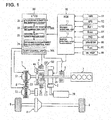
- FIG. 1 there is shown the schematic diagram illustrating a powertrain of an electric vehicle equipped with the continuously variable transmission of the embodiment and its control system.
- the vehicle is constructed as a hybrid vehicle equipped with an engine (an internal combustion engine) 1, a motor generator (an electric motor with a power generation function, hereinafter referred to as simply "MG") 2, a continuously variable transmission (hereinafter referred to as “CVT”) 3, serves as an automatic transmission having a forward/reverse changeover mechanism 4 and a variator (a continuously variable transmission mechanism) 5, a first clutch (hereinafter referred to as simply “CL1”) 6, a second clutch (hereinafter referred to as simply "CL2”) 7, a differential gear 8, and drive road wheels 9, 9.
- an engine an internal combustion engine
- MG motor generator
- CVT continuously variable transmission
- the hybrid vehicle has the first clutch 6 interposed between the engine 1 and MG2.
- the hybrid vehicle has a HEV mode in which the first clutch 6 is engaged and an EV mode in which the first clutch 6 is disengaged (released).
- the HEV mode is comprised of an engine only travelling mode in which the vehicle is propelled by using only the engine 1 as a power source and a combined travelling mode in which torque of MG2 is added to torque of engine 1.
- the second clutch 7 is interposed between MG2 and the variator 5 of CVT3.
- the output shaft of engine 1 and the input side of the rotation shaft 2A of MG2 are connected via the variable torque-capacity first clutch 6.
- the output side of the rotation shaft 2A of MG2 and the input shaft of continuously variable transmission 3 are connected via the forward/reverse changeover mechanism 4 (i.e., the second clutch 7).
- the output shaft of CVT3 is connected via the differential gear 8 to drive road wheels 9, 9.
- the first clutch 6 In the HEV mode, the first clutch 6 is engaged, and thus a combined power of the power inputted via the first clutch 6 from the engine 1 and the power inputted from MG2 is inputted via the second clutch 7 into CVT3, and then the input rotation is speed-changed, and thus the speed-changed rotation is outputted from the CVT to the drive road wheels 9, 9.
- oil pump 50 a mechanical oil pump (hereinafter referred to as simply “oil pump” or “mechanical OP”) 50 is connected to the rotation shaft 2A of MG2.
- Oil pump 50 rotates according to rotation of MG2, so as to produce a discharge amount and discharge pressure according to its rotation speed.
- the pressure of oil discharged from the oil pump is regulated or adjusted to a predetermined pressure through the use of a pressure regulator.
- hydraulic oil (oil pressure) from the oil pump 50 is supplied to respective oil chambers of the first clutch 6, the second clutch 7, and a primary pulley 51 and a secondary pulley of variator 5 (described later).
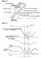
- FIG. 2b there is shown the graph illustrating the correlation between the rotational frequency (see the abscissa axis) and oil pressure (see the ordinate axis) of the mechanical oil pump (mechanical OP) 50 driven by MG2.
- the mechanical oil pump has a characteristic such that, as the rotation speed (the rotational frequency) decreases, the discharge oil pressure also decreases in accordance with a decrease in the rotation speed. Therefore, when the rotation speed of MG2 decreases, the rotation speed of oil pump 50 also decreases, and thus the oil pressure decreases. When the oil pressure decrease proceeds, the oil amount balance becomes severe, and thus an insufficiency of the oil pressure occurs. Owing to the insufficient oil pressure, a belt slippage occurs.
- HCM Hybrid Control Module
- ATCU Automatic transmission Control Unit
- CVT 3 CVT 3 under control of HCM10
- each of HCM10 and ATCU30 comprises a microcomputer constituted of a central processing unit (CPU), a read only memory (ROM), a random access memory (RAM), and an input-output interface (I/O interface), and the like.
- HCM10 has various kinds of control functions for the vehicle, in particular, a function (a functional element, i.e., an engine control unit) 11 that controls the engine 1, a function (a functional element, i.e., a motor control unit) 12 that controls the motor generator 2, for integrally controlling the engine 1 and the motor generator 2. Additionally, HCM10 is configured to output information about commands, related to shifting, for example a target transmission ratio RATIO_t and a target primary rotation speed Npri_t and the like into the ATCU30.
- a function a functional element, i.e., an engine control unit
- a function a functional element, i.e., a motor control unit 12 that controls the motor generator 2
- HCM10 is configured to output information about commands, related to shifting, for example a target transmission ratio RATIO_t and a target primary rotation speed Npri_t and the like into the ATCU30.
- HCM10 is connected to various sensors/switches, such as an inhibitor switch (IHSW) 91 for detecting a shift position of a shift lever (nowt shown) and for outputting a shift range signal corresponding to the detected shift position, an accelerator position sensor (APS) 92 for detecting an accelerator-pedal operation amount (an accelerator opening) APO, a primary pulley rotation sensor 93 for detecting an actual rotation speed (an actual primary rotation speed) Npri_r of the primary pulley 51 of the variator 5 (described later), a secondary pulley rotation sensor 94 for detecting an actual rotation speed (an actual secondary rotation speed) Nsec_r of the secondary pulley 52 of the variator 5 (described later), a throttle opening sensor 95 for detecting a throttle valve opening (a throttle opening) TVO, a brake switch 96 for detecting the presence or absence of the operation of a brake pedal (not shown), a secondary oil pressure sensor 97 for detecting an actual oil pressure (a secondary oil pressure) Psec_r in the oil chamber of the
- a target primary rotation speed Npri_t is set within the HCM10, based on information about the accelerator opening APO, a vehicle speed Vsp, a brake signal, and the like. By the way, the vehicle speed Vsp can be calculated or derived from the secondary pulley rotation speed Nsec. Also, HCM10 is configured to set the target primary rotation speed Npri_t such that the target primary rotation speed increases or decreases depending on a downshift request or an upshift request based on a driver's shift-lever operation.
- the first clutch 6 is provided to connect and disconnect the engine 1 to and from the motor generator 2. For instance, a wet multiple-disk friction clutch is applied to the first clutch. Engagement and disengagement (release) of the first clutch 6 are controlled by a first clutch oil pressure, which is produced by a hydraulic unit (not shown). This hydraulic unit is controlled by the ATCU30 responsively to a control command corresponding to a travelling mode from HCM10.
- HCM10 is configured to determine, based on the vehicle speed Vsp, acceleration and deceleration, the accelerator-pedal operation by the driver, and a state of charge of a battery 20 for driving the vehicle, whether or not a vehicle driving force of engine 1 is required, in order to select a travelling mode and to set respective operating states of the first clutch 6 and the engine 1.
- the first clutch 6 is brought into engagement such that the vehicle enters into an HEV mode.
- the engine 1 is stopped and at the same time the first clutch 6 is released, such that the vehicle enters into an EV mode.
- a forward clutch 7a and a reverse brake 7b which are both incorporated in the forward/reverse changeover mechanism 4 constructed by a planetary gear 4A, are applied to the second clutch 7. That is to say, during forward travelling, the forward clutch 7a serves as the second clutch 7. Conversely during reverse travelling, the reverse brake 7b serves as the second clutch 7.
- a wet multiple-disk friction clutch which is operable in any one of a completely engaged state, a slip-engaged state (a slip state), and a release state, is applied to each of the forward clutch 7a and the reverse brake 7b.
- the forward clutch 7a and the reverse brake 7b are both controlled by a second clutch oil pressure, which is produced by the hydraulic unit (not shown). Selection of any one clutch control mode of the completely engaged state, the slip-engaged state, and the release state is performed by means of a clutch control part (clutch control means, not shown) of HCM10 depending on a travelling mode.
- a third travelling mode (hereinafter referred to as "WSC (Wet Start Clutch) mode") is provided to permit the second clutch 7 to enter into the slip-engaged state.
- WSC Wet Start Clutch
- HCM10 places the MG2 into a motor rotation speed control mode, and simultaneously places the second clutch 7 into slip-engagement with a transmission torque capacity corresponding to a required driving force.
- HCM10 sets the target primary rotation speed Npri_t in a similar manner to usual shift control, and then, in order to bring the actual primary pulley rotation speed Npri_r into the target primary rotation speed Npri_t, HCM10 controls a slip-engaged state between MG2 and the second clutch 7, as follows. First of all, HCM10 sets a target differential rotation ⁇ N CL2_ t of the second clutch 7 based on information about the shift range, accelerator opening APO, and vehicle speed Vsp, and then calculates a target rotation (a target motor rotation speed) Nm_t of MG2 based on the target primary rotation speed Npri_t and the target differential rotation ⁇ N CL2_ t, for controlling the rotation speed of MG2.
- HCM10 calculates an actual differential rotation AN CL2_ r based on the actual primary pulley rotation speed Npri_r and the actual rotation speed Nm_r of MG2, and then, in order to bring the actual differential rotation ⁇ N CL2_ r into the target differential rotation ⁇ N CL2_ t, HCM10 controls the oil pressure supplied to the second clutch 7.
- HCM10 performs control according to the target primary rotation speed Npri_t.
- torque distribution of the respective power sources is controlled according to the state of charge of battery 20, the oil temperature, and the brake operational state, as well as accelerator opening APO and vehicle speed Vsp.
- CVT3 is provided with the forward/reverse changeover mechanism 4 and variator 5.
- Variator 5 has the primary pulley 51, the secondary pulley 52, and an endless power-transmission member (hereinafter referred to as simply "belt”), such as a belt or a chain, wound around these pulleys 51, 52.
- belt endless power-transmission member
- ATCU30 has a shift control unit 30A and an abnormality monitoring unit 30B as functional elements.
- Shift control unit 30A sets an oil pressure of the first clutch 6, an oil pressure of each of the forward clutch 7a and the reverse brake 7b of the forward/reverse changeover mechanism 4, oil pressures (i.e., a primary pulley pressure and a secondary pulley pressure) of the primary pulley 51 and the secondary pulley 52 of variator 5, respectively.
- the shift control unit is configured to produce the respective set oil pressures by controlling electromagnetic valve solenoids (i.e., a primary solenoid related to the primary pulley pressure and a secondary solenoid related to the secondary pulley pressure) incorporated in the hydraulic unit, for oil-pressure supply.
- Shift control unit 30A is provided with a clutch control part (clutch control means) for controlling the second clutch (the forward clutch 7a, the reverse brake 7b).
- the clutch control part of shift control unit 30A operates in cooperation with the clutch control part of HCM10.
- the clutch control part of shift control unit 30A controls an engagement state of the second clutch 7 in accordance with the selected clutch control mode.
- the clutch control part of the shift control unit utilizes slip-engagement, so as to perform smooth switching between the completely engaged state and the completely disengaged state, while allowing a plurality of friction disks to slip into and out of engagement.
- HCM10 places the MG2 into a motor rotation speed control mode.
- the shift control unit 30A responds to a command from the HCM10, such that the second clutch 7 is slip-engagement-controlled in order to attain the target differential rotation ⁇ N CL2_ t of the second clutch.
- shift control unit 30A sets a target transmission ratio (a target pulley ratio) RATIO_t of variator 5, and then controls the primary pulley pressure and the secondary pulley pressure so as to achieve the target transmission ratio without any occurrence of a belt slippage.
- the target transmission ratio RATIO_t is set such that the target primary rotation speed Npri_t inputted from HCM10 can be achieved.
- abnormality monitoring unit 30B monitors the differential-rotation state between an input and an output of the second clutch 7, the actual rotation speed Nm_r of MG2, the divergence state where the actual rotation speed Nm_r of MG2 deviates to a low speed side with respect to the target rotation speed Nm_t of MG2, and a speed decreasing state of the actual rotation speed Nm_r of MG2, for determining an erroneous engagement abnormality.
- abnormality monitoring unit 30B determines whether or not a preset permission condition is satisfied, and then initiates the abnormality determination processing when the preset permission condition is satisfied. Also, in determining the above-mentioned erroneous engagement abnormality, a first check is made to determine whether or not an abnormality temporary determination condition is satisfied, and then a second check is made to determine whether or not an abnormality confirmation condition is satisfied when the abnormality temporary determination condition is satisfied. In this manner, the abnormality determination processing is performed through a two-stage check.
- abnormality monitoring unit 30B performs control to handle or cope with this erroneous engagement abnormality.
- abnormality monitoring unit 30B is provided with a permission condition determination part (permission condition determination means) 31, an abnormality temporary determination part (abnormality temporary determination means) 32, an abnormality confirmation part (abnormality confirmation means) 33, and an erroneous engagement handling control part (erroneous engagement handling control means) 34.
- a permission condition based on which a determination of the permission condition determination part 31 is made, is hereinafter explained.
- the permission condition corresponds to a prerequisite for the occurrence of a situation where the second clutch 7 is erroneously engaged and thus the oil amount balance becomes severe.
- the permission condition the following conditions (a) to (e) are provided.
- the permission condition is determined to be satisfied, when these conditions (a)-(e) are all satisfied.
- the condition (a) can be determined based on the shift range signal outputted from IHSW91.
- the shift range signal is a range other than a P (parking) or an N (neutral) range (for example a D (drive) or an R (reverse) range)
- the condition (a) is satisfied.
- the conditions (b) and (c) can be acquired or determined based on instruction information from HCM10.
- the condition "the elapsed time reaches the predetermined time” included in the condition (b) is provided, taking account of a response delay of the second clutch 7 in a transition to either a slip-engaged state or a release state from the time when switching of the clutch control mode from the completely engaged state to either the slip-engaged state or the release state occurs.
- condition (d) means that the vehicle is in a low-speed travelling state in which the vehicle enters into the WSC mode.
- condition (e) is provided to exclude a situation where the oil temperature of hydraulic oil is low, for instance immediately after the vehicle has started.
- Abnormality temporary determination part 32 determines whether or not an abnormality temporary determination condition is satisfied, when the permission condition has been satisfied.
- the abnormality temporary determination condition the following conditions, namely, a first temporary determination condition [a condition (1) described hereunder] and a second temporary determination condition [a condition (2) described hereunder] are provided.
- the set time period is a minute time to eliminate the influence of the reading accuracy of the sensor.
- HCM10 controls rotation (rotation speed) of MG2.
- HCM10 controls rotation (rotation speed) of MG2, while giving the target motor rotation speed Nm_t determined based on a target idle speed.
- the target idle speed that is, an HEV idle speed
- a speed value higher than or equal to an EV idle speed (a lower-limit rotation speed) corresponding to a minimum rotation speed during an EV travelling mode is set or used.
- the rotation speed of MG2 follows the rotation speed of the primary pulley 51, and thus no differential rotation (no input-and-output rotation speed difference) of the second clutch 7 occur. Therefore, the condition (1) becomes satisfied. Additionally, the actual motor rotation speed Nm_r deviates to a low speed side from the target motor rotation speed Nm_t. As the vehicle speed decreases, the divergence (the deviation) gradually increases, and thus the condition (2) becomes satisfied.
- the conditions (1), (2) become both satisfied, and thus the abnormality temporary determination condition becomes satisfied.
- the abnormality confirmation condition including the conditions (3), (4) becomes satisfied. Since the conditions (1), (2) have already been both satisfied, there is no need for confirming the continuation of the condition (3) based on a count value to be counted by a timer. At the time when the condition (3) has been satisfied, that is, the actual rotation speed Nm_r of MG2 has reduced to below the lower-limit rotation speed (the EV idle speed), it is possible to conform an erroneous engagement abnormality of the second clutch 7.
- FIG. 5 there is shown the graph illustrating a determination area for the erroneous clutch engagement determination.
- rotation of MG2 follows rotation of the primary pulley 51, and also decreases according to a decrease of vehicle speed Vsp.
- Vsp vehicle speed
- a check is made to determine whether the abnormality temporary determination condition including the conditions (1), (2) is satisfied.
- the EV idle speed the lower-limit rotation speed
- Erroneous engagement handling control part 34 executes torque adjustment control (in the shown embodiment, torque down control in which torque is decreased) to adjust an output torque of the driving source (corresponding to an input torque to CVT3) according to the secondary oil pressure Psec_r detected by the secondary oil pressure sensor 97, after a confirmation on an erroneous engagement abnormality has been made by means of the abnormality confirmation part 33.
- the driving source corresponds to the engine 1 and MG2.
- the driving source varies depending on a selected travelling mode. For instance, in an HEV mode, the engine 1 and MG2 serve as the driving source. In an EV mode, MG2 serves as the driving source. For the purpose of simplification of the disclosure, a case where MG2 serves as the driving source is exemplified.
- torque down control is executed after an abnormality confirmation has been made by means of the abnormality confirmation part 33, but a permission condition is also set for the torque down control itself.
- the permission condition for torque down control the following conditions (a'), (b') are provided. When these conditions (a'), (b') are both satisfied, the permission condition is determined to be satisfied.
- an abnormality (a failure) of IHSW91 abnormal rotation (malrotation) of MG2
- an abnormality (a failure) of primary pulley rotation sensor 93 an abnormality (a failure) of secondary pulley rotation sensor 94
- an abnormality (a failure) of throttle opening sensor 95 an abnormality (a failure) of secondary oil pressure sensor 97
- an electrical abnormality of the hydraulic pressure control solenoid of the second clutch 7, data communication abnormality and the like occurs, the torque down control is inhibited.
- the torque down condition (1') becomes unsatisfied
- the permission condition for torque down control becomes unsatisfied
- the torque down control is cancelled or released.
- target motor rotation speed Nm_t is set for controlling the rotation speed of MG2.
- torque down control for decreasing the output torque of MG2 in accordance with the secondary oil pressure Psec_r is executed.
- FIG. 6 there is shown the time chart illustrating torque down control. As indicated by the solid line (TORQUE DOWN ACCORDING TO SEC PRESSURE) in FIG. 6 , immediately when an erroneous engagement abnormality has been confirmed at the time t3, torque down control is executed in concert with the secondary oil pressure Psec_r.
- the output torque decrease is limited to the lower limit value.
- the lower limit value is set depending on the gear ratio.
- the rotation speed of MG2 fluctuates up and down in a low speed range, and thus a slip and a grip of belt 53 are repeated, as shown in FIG. 2b .
- the secondary oil pressure Psec_r fluctuates up and down.
- the up-and-down fluctuations affects operation on a torque-down request (a torque-down request value) based on the secondary oil pressure Psec_r.
- the torque down control when an increase request for the output torque of MG2, for example a mode transition from an accelerator-ON state to an accelerator-OFF state, is present, the torque down control is cancelled or released, so as to recover (increase) the output torque of MG2.
- the increase of the output torque of MG2 is executed, while limiting the time rate of increase to a prescribed time rate of increase (see a "RAMP A" shown in the time chart).
- FIG. 7 there is shown the time chart illustrating fluctuations of the secondary oil pressure Psec, motor rotation speed Nm, primary rotation speed Npri, and secondary rotation speed Nsec, when, during execution of torque down control in an accelerator-OFF state, a transition to an accelerator-ON state occurs at the time t6 and then the output torque of MG2 recovers (increases) according to a given time rate of increase based on the accelerator opening.
- a situation where the torque down control is cancelled includes a situation where the torque down condition (1') becomes unsatisfied and a situation where the permission condition (a') becomes unsatisfied.
- the recovery (the increase) of the output torque of MG2 is executed while limiting the time rate of increase to a prescribed time rate of increase.
- the prescribed time rate of increase for limiting torque-increase speed may be changed or altered depending on whether or not the accelerator is in its ON state.
- the output torque of MG2 is increased, while limiting the time rate of increase (the torque-increase speed) to a prescribed ramp B.
- the output torque of MG2 is increased, while limiting the time rate of increase (the torque-increase speed) to a prescribed ramp C gentler than the ramp B.
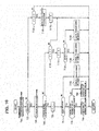
- the erroneous clutch engagement determination unit and the erroneous clutch engagement handling control device of the embodiment of the invention are constructed as discussed above. Hence, as shown in the flowcharts of FIGS. 9-10 , an erroneous clutch engagement determination and an erroneous clutch engagement handling control can be executed.
- the flowcharts of FIGS. 9-10 are initiated when a key switch becomes turned ON, and repeatedly executed at a predetermined control cycle until such time an abnormality confirmation has been made or the key switch has been turned OFF.
- the determination processing of the permission condition including the conditions (a)-(e) is executed (step S10).
- the determination of the permission condition is initiated after having confirmed that the current situation does not correspond to a situation corresponding to the previously-described inhibition condition.
- a check is made to determine whether or not the permission condition is satisfied (step S20).
- the routine is returned.
- the determination processing of the abnormality temporary determination condition for an erroneous engagement abnormality is executed (step S30). The details of the determination processing of the abnormality temporary determination condition will be described later.
- step S40 a check is made to determine whether or not the abnormality temporary determination condition is satisfied.
- the routine is returned.
- the determination processing of the abnormality confirmation condition corresponding to only the condition (3) is executed (step S50), since the abnormality confirmation condition corresponding to the condition (4) has already been satisfied.
- the determination processing of the abnormality confirmation condition is made by determining whether or not the actual rotation speed Nm_r is lower than the EV idle speed, which is the lower-limit rotation speed.
- step S70 an abnormality confirmation is made (step S70), and thus an abnormal signal is outputted to the HCM10 (step S80), and then a command to execute torque down control, which serves as abnormality handling control, is instructed to the HCM10, and then a limp home control mode is executed (a limp home capability is permitted) (step S90).
- the determination processing of the abnormality temporary determination condition is executed as shown in FIG. 9b .
- the abbreviation "TM" in FIG. 9b means a timer value (counts of a timer). The timer counts a time or a time period during which the conditions (1), (2) are both satisfied, as the timer value "TM".
- a check is made to determine whether the condition (1) is satisfied, that is, there is no differential rotation (no input-and-output rotation speed difference) between the input side and the output side of the second clutch 7 (step S31).
- the timer value TM is reset to "0" (step S37), and the routine is returned.
- a check is made to determine whether the condition (2) is satisfied, that is, the actual rotation speed Nm_r of MG2 deviates more than a predetermined deviation to a low speed side from the target rotation speed Nm_t (step S32).
- the timer value TM is reset to "0" (step S37), and the routine is returned. Conversely when the actual rotation speed Nm_r of MG2 deviates more than a predetermined deviation to a low speed side from the target rotation speed Nm_t, the timer value TM is incremented or counted up (step S33).
- a predetermined value TM1 a predetermined count period
- the routine is returned.
- an abnormality temporary determination is made, that is, the presence of an erroneous engagement abnormality is temporarily determined (step S35).
- the erroneous engagement handling control is executed as shown in FIG. 10 .
- the abbreviation “F” in FIG. 10 means a control flag.
- the flag “F” is set to “1" during execution of torque down control, and otherwise reset to "0".
- step T10 the determination processing of the permission condition including the conditions (a'), (b') is executed (step T10).
- the determination of the permission condition is initiated after having confirmed that the current situation does not correspond to a situation corresponding to the previously-described inhibition condition.
- a check is made to determine whether or not the permission condition is satisfied (step T20).
- the flag "F” is not set to "1”
- the routine is returned.
- the flag "F” is "1”
- the torque down control which is executed currently, is immediately cancelled (step T160). This wording "immediate cancellation” means that the increase of the output torque of MG2 is immediately executed without limiting a time rate of increase.
- the flag "F” is reset to "0" (step T170), and then the routine is returned.
- torque down determination processing having the condition (1') is made. That is, a check is made to determine whether a state where the motor rotation speed Nm_r is less than a predetermined value (EV idle speed) has continued for a predetermined count period (step T30).
- the flag "F" is set to "1" (step T50).
- the torque down (torque down control) is executed, targeting at the lower limit value (step T80).
- the torque down (torque down control) is executed, targeting at the torque-down request value (step T90).
- step T60 determines that the accelerator is placed in the ON state, the torque down control is cancelled, and then the increase of the output torque of MG2 is executed while limiting the time rate of increase to a prescribed time rate of increase (ramp A) (step T100).
- step T40 determines that the torque down should not be executed
- a check is made to determine whether or not the flag "F" is "1", that is, the system is placed in the torque down control at the current control cycle (step T110).
- the routine is returned.
- the flag "F” is "1” and thus the system is placed in the torque down control at the current control cycle
- the flag "F” is reset to "0" (step T112), and then a check is made to determine whether or not the accelerator is placed in the ON state (step T120).
- step T130 When it is determined that the accelerator is placed in the ON state, the torque down control is cancelled, and then the increase of the output torque of MG2 is executed while limiting the time rate of increase to a prescribed time rate of increase (ramp B) (step T130). Conversely when it is determined that the accelerator is placed in the OFF state, the torque down control is cancelled, and then the increase of the output torque of MG2 is executed while limiting the time rate of increase to a prescribed time rate of increase (ramp (gradient) C gentler than ramp (gradient) B) (step T140).
- an abnormality is temporarily determined.
- the erroneous engagement abnormality is confirmed on the basis of the abnormality confirmation condition (3), upon which the abnormality to be handled can be certainly determined, under a situation where the abnormality confirmation condition (4), which is identical to the abnormality temporary determination condition (1), has been satisfied.
- the time (the set time period) for an abnormality confirmation based on the abnormality confirmation condition (3) can be preset as a time period merely required to ensure the reliability of a detection value. Hence, it is possible to shorten the time period from the occurrence of an abnormality to an abnormality confirmation.
- a hybrid vehicle is exemplified as a vehicle, but the inventive concept may be applied to any vehicle, in which an electric motor serves as a driving power source, for example, an electric vehicle, in which only the electric motor is a driving power source.
Landscapes
- Engineering & Computer Science (AREA)
- General Engineering & Computer Science (AREA)
- Mechanical Engineering (AREA)
- Chemical & Material Sciences (AREA)
- Combustion & Propulsion (AREA)
- Transportation (AREA)
- Automation & Control Theory (AREA)
- Control Of Transmission Device (AREA)
- Hybrid Electric Vehicles (AREA)
- Hydraulic Clutches, Magnetic Clutches, Fluid Clutches, And Fluid Joints (AREA)
- Electric Propulsion And Braking For Vehicles (AREA)
Claims (8)
- Dispositif de commande de gestion de mise en prise d'embrayage erronée pour effectuer une commande pour gérer une mise en prise erronée où un embrayage de prise à friction (7) est complètement mise en prise de manière erronée dans un véhicule ayant un moteur électrique (2) servant de source d'entraînement du véhicule, une pompe à huile mécanique (50) raccordée en entraînement au moteur électrique (2), une transmission à variation continue (3) équipée d'un variateur hydraulique (5) actionné en utilisant une pression d'huile de la pompe à huile (50) et ayant une poulie primaire (51), une poulie secondaire (52), et un élément de transmission de puissance sans fin (53) enroulé autour de ces poulies (51, 52), l'embrayage de prise à friction (7) interposé entre le moteur électrique (2) et la transmission à variation continue (3), des moyens de commande d'embrayage (30) pour commander l'embrayage (7) de telle sorte que l'embrayage (7) entre dans un quelconque mode de commande d'embrayage parmi un état complètement en prise, un état en prise par glissement, et un état de libération en fonction d'un état de déplacement du véhicule, et des moyens de commande de véhicule (10) pour commander le moteur électrique (2) de telle sorte que le moteur électrique (2) tourne à une vitesse de rotation cible (Nm_t) sur la base d'une demande de sortie au moteur électrique (2) et du mode de commande d'embrayage ;
le dispositif de commande de gestion de mise en prise d'embrayage erronée comprenant :une unité de détermination de mise en prise d'embrayage erronée (32, 33) pour déterminer que l'embrayage (7) est dans un état de mise en prise erronée lorsqu'une condition de détermination prédéterminée est satisfaite ;des moyens de détection de pression d'huile secondaire (97) pour détecter une pression d'huile secondaire (Psec_r), qui est une pression hydraulique de poulie de la poulie secondaire (52) ;caractérisé par :
des moyens de commande de gestion de mise en prise erronée (34) pour exécuter une commande d'ajustement de couple afin d'ajuster un couple de sortie de la source d'entraînement en fonction de la pression d'huile secondaire (Psec_r) détectée par les moyens de détection de pression d'huile secondaire (97) lorsqu'il est déterminé que l'embrayage (7) est dans l'état de mise en prise erronée par l'unité de détermination de mise en prise d'embrayage erronée. - Dispositif de commande de gestion de mise en prise d'embrayage erronée selon la revendication 1, dans lequel :
les moyens de commande de gestion de mise en prise erronée (34) exécutent la commande d'ajustement de couple, tout en établissant une valeur limite inférieure de demande d'abaissement de couple qui maintient une vitesse de rotation de la source d'entraînement nécessaire à une transmission de puissance. - Dispositif de commande de gestion de mise en prise d'embrayage erronée selon les revendications 1 ou 2, dans lequel :
la commande d'ajustement de couple est exécutée pour maintenir le couple de sortie de la source d'entraînement lorsque la pression d'huile secondaire (Psec_r) augmente, et pour diminuer le couple de sortie de la source d'entraînement en fonction de la pression d'huile secondaire (Psec_r) lorsque la pression d'huile secondaire (Psec_r) diminue. - Dispositif de commande de gestion de mise en prise d'embrayage erronée selon l'une quelconque des revendications précédentes 1 à 3, dans lequel :
les moyens de commande de gestion de mise en prise erronée (34) limitent une cadence temporelle d'augmentation du couple de sortie, lorsqu'une demande d'augmentation du couple de sortie de la source d'entraînement est présente pendant l'exécution de la commande d'ajustement de couple et ainsi le couple de sortie de la source d'entraînement augmente. - Dispositif de commande de gestion de mise en prise d'embrayage erronée selon l'une quelconque des revendications précédentes 1 à 4, dans lequel :
les moyens de commande de gestion de mise en prise erronée (34) augmentent et rétablissent progressivement le couple de sortie de la source d'entraînement à une cadence temporelle d'augmentation prescrite, lorsque la commande d'ajustement de couple se termine. - Dispositif de commande de gestion de mise en prise d'embrayage erronée selon l'une quelconque des revendications précédentes 1 à 5, dans lequel :
l'unité de détermination de mise en prise d'embrayage erronée comprend en outre des moyens de détection de distance (91) pour détecter une distance sélectionnée de la transmission à variation continue (3), des moyens de détection de vitesse de véhicule pour détecter une vitesse de véhicule (Vsp) du véhicule, des moyens de détection de rotation de moteur pour détecter une vitesse de rotation (Nm_r) du moteur électrique (2), des moyens de détection de différence de vitesse de rotation pour détecter une différence de vitesse de rotation d'entrée et sortie (ΔNCL2_r) de l'embrayage (7), des moyens de détermination de condition d'autorisation pour déterminer, sur la base d'informations concernant le mode de commande d'embrayage sélectionné par les moyens de commande d'embrayage (30) et d'informations de détection provenant des moyens de détection de distance (91) et des moyens de détection de vitesse de véhicule, si une première condition dans laquelle le mode de commande d'embrayage n'est pas l'état complètement en prise, une deuxième condition dans laquelle la distance sélectionnée est une distance de déplacement et une troisième condition dans laquelle la vitesse de véhicule (Vsp) est inférieure à une valeur prédéterminée sont toutes satisfaites et pour déterminer qu'une condition d'autorisation est satisfaite lorsque la première condition, la deuxième condition, et la troisième condition sont toutes satisfaites, des moyens de détermination temporaire d'anomalie (32) pour déterminer, sur la base d'informations de détection provenant des moyens de détection de différence de vitesse de rotation lorsque la condition d'autorisation a été déterminée comme étant satisfaite par les moyens de détermination de condition d'autorisation (31), si une condition de détermination temporaire d'anomalie, comprenant une première condition de détermination temporaire où il n'y a aucune différence de vitesse de rotation d'entrée et sortie de l'embrayage (7), est satisfaite ou non, et des moyens de confirmation d'anomalie (33) pour déterminer, sur la base d'informations de détection provenant des moyens de détection de rotation de moteur lorsque la condition de détermination temporaire d'anomalie a été déterminée comme étant satisfaite par les moyens de détermination temporaire d'anomalie (32), si une condition de confirmation d'anomalie où la vitesse de rotation (Nm_r) du moteur électrique (2) est inférieure à une vitesse de rotation limite inférieure préétablie (Nm_i) est satisfaite ou non, et pour confirmer que l'embrayage (7) est dans l'état de mise en prise erronée lorsque la condition de confirmation d'anomalie est satisfaite. - Dispositif de commande de gestion de mise en prise d'embrayage erronée selon la revendication 6, dans lequel :
la condition de détermination temporaire d'anomalie comprend en outre une seconde condition de détermination temporaire dans laquelle la vitesse de rotation (Nm_r) du moteur électrique (2) s'écarte de plus d'un écart prédéterminé vers un côté de faible vitesse par rapport à la vitesse de rotation cible (Nm_t), et les moyens de détermination temporaire d'anomalie (32) déterminent, sur la base des informations de détection provenant des moyens de détection de différence de vitesse de rotation et des informations de détection provenant des moyens de détection de rotation de moteur, si la première condition de détermination temporaire et la seconde condition de détermination temporaire sont satisfaites ou non, et déterminent que la condition de détermination temporaire d'anomalie est satisfaite lorsque la première condition de détermination temporaire et la seconde condition de détermination temporaire sont toutes deux satisfaites. - Dispositif de commande de gestion de mise en prise d'embrayage erronée selon la revendication 7, dans lequel :
les moyens de détermination temporaire d'anomalie (32) déterminent que la condition de détermination temporaire d'anomalie est satisfaite lorsqu'un état dans lequel la première condition de détermination temporaire et la seconde condition de détermination temporaire sont toutes deux satisfaites s'est poursuivi pendant plus d'une période de temps établie.
Applications Claiming Priority (2)
| Application Number | Priority Date | Filing Date | Title |
|---|---|---|---|
| JP2016016443 | 2016-01-29 | ||
| PCT/JP2017/002867 WO2017131134A1 (fr) | 2016-01-29 | 2017-01-27 | Dispositif de commande traitant une mise en prise d'embrayage erronée |
Publications (3)
| Publication Number | Publication Date |
|---|---|
| EP3409979A1 EP3409979A1 (fr) | 2018-12-05 |
| EP3409979A4 EP3409979A4 (fr) | 2018-12-19 |
| EP3409979B1 true EP3409979B1 (fr) | 2019-12-04 |
Family
ID=59398485
Family Applications (1)
| Application Number | Title | Priority Date | Filing Date |
|---|---|---|---|
| EP17744364.5A Active EP3409979B1 (fr) | 2016-01-29 | 2017-01-27 | Dispositif de commande traitant une mise en prise d'embrayage erronée |
Country Status (6)
| Country | Link |
|---|---|
| US (1) | US10598277B2 (fr) |
| EP (1) | EP3409979B1 (fr) |
| JP (1) | JP6614588B2 (fr) |
| KR (1) | KR102060910B1 (fr) |
| CN (1) | CN108431463B (fr) |
| WO (1) | WO2017131134A1 (fr) |
Families Citing this family (14)
| Publication number | Priority date | Publication date | Assignee | Title |
|---|---|---|---|---|
| JP6808298B2 (ja) * | 2017-12-15 | 2021-01-06 | ジヤトコ株式会社 | 自動変速機の制御装置 |
| CN109595321A (zh) * | 2018-12-30 | 2019-04-09 | 芜湖万里扬变速器有限公司 | 纯电动车辆用无级变速系统 |
| US11242927B2 (en) * | 2019-05-23 | 2022-02-08 | GM Global Technology Operations LLC | Robust hydraulic system disturbance detection and mitigation |
| WO2021006086A1 (fr) * | 2019-07-08 | 2021-01-14 | ジヤトコ株式会社 | Dispositif de diagnostic pour boîte de vitesses automatique |
| JP7372088B2 (ja) | 2019-09-10 | 2023-10-31 | 株式会社Subaru | ハイブリッド車両システム |
| US11112004B2 (en) * | 2019-10-01 | 2021-09-07 | Allison Transmission, Inc. | Transmission control systems to adjust clutch pressure and torque based on grade |
| DE102019127419A1 (de) * | 2019-10-11 | 2021-04-15 | Schaeffler Technologies AG & Co. KG | Notbetriebsverfahren für ein Umschlingungsgetriebe bei Anpressdruckabfall, sowie Antriebsstrang |
| KR102821809B1 (ko) * | 2020-04-21 | 2025-06-18 | 현대자동차주식회사 | 차량 및 그 제어 방법 |
| WO2021213580A1 (fr) * | 2020-04-21 | 2021-10-28 | Schaeffler Technologies AG & Co. KG | Procédé et système de fluide pour l'actionnement d'un composant de transmission et d'un dispositif de déconnexion |
| JP7384118B2 (ja) * | 2020-06-16 | 2023-11-21 | トヨタ自動車株式会社 | 異常要因判定装置、車両用制御装置、および車両用制御システム |
| CN111810629B (zh) * | 2020-07-22 | 2022-01-07 | 钦州绿传科技有限公司 | 一种车辆中机械泵失效的检测及控制方法及车辆 |
| JP7392606B2 (ja) | 2020-08-07 | 2023-12-06 | トヨタ自動車株式会社 | 動力伝達装置の異常判定装置 |
| JP7724102B2 (ja) * | 2021-08-20 | 2025-08-15 | 株式会社Subaru | 電気自動車 |
| JP7666352B2 (ja) * | 2022-02-10 | 2025-04-22 | トヨタ自動車株式会社 | 制御装置 |
Family Cites Families (15)
| Publication number | Priority date | Publication date | Assignee | Title |
|---|---|---|---|---|
| JPH02169333A (ja) * | 1988-12-22 | 1990-06-29 | Mazda Motor Corp | 無段変速機を備えた車両のエンジン制御装置 |
| JPH0331035A (ja) * | 1989-06-29 | 1991-02-08 | Mazda Motor Corp | 車両のスリップ制御装置 |
| JP2002051407A (ja) * | 2000-08-03 | 2002-02-15 | Toyota Motor Corp | パワートレーンの制御装置 |
| JP4200669B2 (ja) * | 2001-05-21 | 2008-12-24 | トヨタ自動車株式会社 | ハイブリッド自動車 |
| JP2004316843A (ja) * | 2003-04-18 | 2004-11-11 | Jatco Ltd | ベルト式無段変速機の制御装置 |
| JP4297286B2 (ja) * | 2006-01-26 | 2009-07-15 | ジヤトコ株式会社 | 自動変速機の制御装置 |
| JP4935268B2 (ja) | 2006-09-21 | 2012-05-23 | 日産自動車株式会社 | 車両の制御装置 |
| US8348797B2 (en) * | 2008-04-04 | 2013-01-08 | GM Global Technology Operations LLC | Hydraulic clutch control system |
| JP5359988B2 (ja) * | 2010-05-18 | 2013-12-04 | トヨタ自動車株式会社 | 車両の制御装置 |
| JP2012206663A (ja) | 2011-03-30 | 2012-10-25 | Jatco Ltd | ハイブリッド車両の変速制御装置 |
| JP2013181554A (ja) * | 2012-02-29 | 2013-09-12 | Nissan Motor Co Ltd | 車両の変速制御装置 |
| JP5926299B2 (ja) * | 2014-01-23 | 2016-05-25 | 富士重工業株式会社 | 無段変速機の異常検知装置、及び、無段変速機の異常検知方法 |
| JP5997193B2 (ja) * | 2014-02-14 | 2016-09-28 | 富士重工業株式会社 | 無段変速機の異常検知装置、及び、無段変速機の異常検知方法 |
| CN103836182A (zh) * | 2014-03-28 | 2014-06-04 | 大陆汽车投资(上海)有限公司 | 配备液力变矩器的带式cvt的控制系统和方法 |
| JP6919985B2 (ja) * | 2017-05-19 | 2021-08-18 | トヨタ自動車株式会社 | 車両用動力伝達装置 |
-
2017
- 2017-01-27 EP EP17744364.5A patent/EP3409979B1/fr active Active
- 2017-01-27 CN CN201780005812.7A patent/CN108431463B/zh active Active
- 2017-01-27 US US16/073,513 patent/US10598277B2/en active Active
- 2017-01-27 WO PCT/JP2017/002867 patent/WO2017131134A1/fr not_active Ceased
- 2017-01-27 KR KR1020187019919A patent/KR102060910B1/ko not_active Expired - Fee Related
- 2017-01-27 JP JP2017563838A patent/JP6614588B2/ja active Active
Non-Patent Citations (1)
| Title |
|---|
| None * |
Also Published As
| Publication number | Publication date |
|---|---|
| EP3409979A4 (fr) | 2018-12-19 |
| CN108431463B (zh) | 2019-12-31 |
| EP3409979A1 (fr) | 2018-12-05 |
| CN108431463A (zh) | 2018-08-21 |
| JP6614588B2 (ja) | 2019-12-04 |
| KR20180093049A (ko) | 2018-08-20 |
| US20190040949A1 (en) | 2019-02-07 |
| US10598277B2 (en) | 2020-03-24 |
| WO2017131134A1 (fr) | 2017-08-03 |
| KR102060910B1 (ko) | 2019-12-30 |
| JPWO2017131134A1 (ja) | 2018-11-01 |
Similar Documents
| Publication | Publication Date | Title |
|---|---|---|
| US10598277B2 (en) | Control device that handles erroneous clutch engagement | |
| JP5252171B2 (ja) | 車両用制御装置 | |
| CN103764977B (zh) | 滑行停止车辆 | |
| JP5605504B2 (ja) | 車両用駆動装置の制御装置 | |
| EP2392839B1 (fr) | Transmission automatique | |
| CN103765055B (zh) | 车辆控制装置及车辆控制方法 | |
| KR101812456B1 (ko) | 하이브리드 차량의 제어 장치 및 그 제어 방법 | |
| CN106062431B (zh) | 车辆控制装置及其控制方法 | |
| JP3678777B2 (ja) | 無段変速機の制御装置 | |
| CN108027054A (zh) | 带式无级变速器及其故障判断方法 | |
| CN106660550B (zh) | 车辆的控制装置及控制方法 | |
| US10724627B2 (en) | Control device for vehicle and control method for vehicle | |
| JP6651368B2 (ja) | クラッチ誤締結判定装置及びこれを用いたクラッチ誤締結対応制御装置 | |
| JP6851699B2 (ja) | 自動変速機のクラッチ滑り診断装置及びクラッチ滑り診断方法 | |
| US11524670B2 (en) | Control device for vehicle and control method for vehicle | |
| US10690238B2 (en) | Device for controlling vehicular variator | |
| JP6124828B2 (ja) | 車両用変速機の制御装置 | |
| JP6595366B2 (ja) | ハイブリッド車両のクラッチ誤解放検出装置及びハイブリッド車両 | |
| JP6670620B2 (ja) | 車両用無段変速機の異常判定装置及び異常時対応装置 | |
| JP2025120864A (ja) | 車両の制御装置 |
Legal Events
| Date | Code | Title | Description |
|---|---|---|---|
| STAA | Information on the status of an ep patent application or granted ep patent |
Free format text: STATUS: THE INTERNATIONAL PUBLICATION HAS BEEN MADE |
|
| PUAI | Public reference made under article 153(3) epc to a published international application that has entered the european phase |
Free format text: ORIGINAL CODE: 0009012 |
|
| STAA | Information on the status of an ep patent application or granted ep patent |
Free format text: STATUS: REQUEST FOR EXAMINATION WAS MADE |
|
| 17P | Request for examination filed |
Effective date: 20180730 |
|
| AK | Designated contracting states |
Kind code of ref document: A1 Designated state(s): AL AT BE BG CH CY CZ DE DK EE ES FI FR GB GR HR HU IE IS IT LI LT LU LV MC MK MT NL NO PL PT RO RS SE SI SK SM TR |
|
| AX | Request for extension of the european patent |
Extension state: BA ME |
|
| A4 | Supplementary search report drawn up and despatched |
Effective date: 20181119 |
|
| RIC1 | Information provided on ipc code assigned before grant |
Ipc: F16H 63/50 20060101ALI20181113BHEP Ipc: F16H 59/70 20060101ALN20181113BHEP Ipc: F16H 61/12 20100101AFI20181113BHEP Ipc: F16H 59/68 20060101ALN20181113BHEP Ipc: F16H 61/662 20060101ALI20181113BHEP |
|
| DAV | Request for validation of the european patent (deleted) | ||
| DAX | Request for extension of the european patent (deleted) | ||
| RIC1 | Information provided on ipc code assigned before grant |
Ipc: F16H 59/70 20060101ALN20190614BHEP Ipc: F16H 63/50 20060101ALI20190614BHEP Ipc: F16H 61/662 20060101ALI20190614BHEP Ipc: F16H 59/68 20060101ALN20190614BHEP Ipc: F16H 61/12 20100101AFI20190614BHEP |
|
| RIC1 | Information provided on ipc code assigned before grant |
Ipc: F16H 61/662 20060101ALI20190702BHEP Ipc: F16H 59/68 20060101ALN20190702BHEP Ipc: F16H 61/12 20100101AFI20190702BHEP Ipc: F16H 63/50 20060101ALI20190702BHEP Ipc: F16H 59/70 20060101ALN20190702BHEP |
|
| GRAP | Despatch of communication of intention to grant a patent |
Free format text: ORIGINAL CODE: EPIDOSNIGR1 |
|
| STAA | Information on the status of an ep patent application or granted ep patent |
Free format text: STATUS: GRANT OF PATENT IS INTENDED |
|
| RIC1 | Information provided on ipc code assigned before grant |
Ipc: F16H 61/662 20060101ALI20190708BHEP Ipc: F16H 59/68 20060101ALN20190708BHEP Ipc: F16H 63/50 20060101ALI20190708BHEP Ipc: F16H 59/70 20060101ALN20190708BHEP Ipc: F16H 61/12 20100101AFI20190708BHEP |
|
| INTG | Intention to grant announced |
Effective date: 20190814 |
|
| GRAS | Grant fee paid |
Free format text: ORIGINAL CODE: EPIDOSNIGR3 |
|
| GRAA | (expected) grant |
Free format text: ORIGINAL CODE: 0009210 |
|
| STAA | Information on the status of an ep patent application or granted ep patent |
Free format text: STATUS: THE PATENT HAS BEEN GRANTED |
|
| AK | Designated contracting states |
Kind code of ref document: B1 Designated state(s): AL AT BE BG CH CY CZ DE DK EE ES FI FR GB GR HR HU IE IS IT LI LT LU LV MC MK MT NL NO PL PT RO RS SE SI SK SM TR |
|
| REG | Reference to a national code |
Ref country code: GB Ref legal event code: FG4D |
|
| REG | Reference to a national code |
Ref country code: CH Ref legal event code: EP |
|
| REG | Reference to a national code |
Ref country code: AT Ref legal event code: REF Ref document number: 1209822 Country of ref document: AT Kind code of ref document: T Effective date: 20191215 |
|
| REG | Reference to a national code |
Ref country code: DE Ref legal event code: R096 Ref document number: 602017009443 Country of ref document: DE |
|
| REG | Reference to a national code |
Ref country code: IE Ref legal event code: FG4D |
|
| REG | Reference to a national code |
Ref country code: NL Ref legal event code: MP Effective date: 20191204 |
|
| REG | Reference to a national code |
Ref country code: LT Ref legal event code: MG4D |
|
| PG25 | Lapsed in a contracting state [announced via postgrant information from national office to epo] |
Ref country code: GR Free format text: LAPSE BECAUSE OF FAILURE TO SUBMIT A TRANSLATION OF THE DESCRIPTION OR TO PAY THE FEE WITHIN THE PRESCRIBED TIME-LIMIT Effective date: 20200305 Ref country code: NO Free format text: LAPSE BECAUSE OF FAILURE TO SUBMIT A TRANSLATION OF THE DESCRIPTION OR TO PAY THE FEE WITHIN THE PRESCRIBED TIME-LIMIT Effective date: 20200304 Ref country code: FI Free format text: LAPSE BECAUSE OF FAILURE TO SUBMIT A TRANSLATION OF THE DESCRIPTION OR TO PAY THE FEE WITHIN THE PRESCRIBED TIME-LIMIT Effective date: 20191204 Ref country code: BG Free format text: LAPSE BECAUSE OF FAILURE TO SUBMIT A TRANSLATION OF THE DESCRIPTION OR TO PAY THE FEE WITHIN THE PRESCRIBED TIME-LIMIT Effective date: 20200304 Ref country code: LT Free format text: LAPSE BECAUSE OF FAILURE TO SUBMIT A TRANSLATION OF THE DESCRIPTION OR TO PAY THE FEE WITHIN THE PRESCRIBED TIME-LIMIT Effective date: 20191204 Ref country code: LV Free format text: LAPSE BECAUSE OF FAILURE TO SUBMIT A TRANSLATION OF THE DESCRIPTION OR TO PAY THE FEE WITHIN THE PRESCRIBED TIME-LIMIT Effective date: 20191204 Ref country code: SE Free format text: LAPSE BECAUSE OF FAILURE TO SUBMIT A TRANSLATION OF THE DESCRIPTION OR TO PAY THE FEE WITHIN THE PRESCRIBED TIME-LIMIT Effective date: 20191204 |
|
| PG25 | Lapsed in a contracting state [announced via postgrant information from national office to epo] |
Ref country code: RS Free format text: LAPSE BECAUSE OF FAILURE TO SUBMIT A TRANSLATION OF THE DESCRIPTION OR TO PAY THE FEE WITHIN THE PRESCRIBED TIME-LIMIT Effective date: 20191204 Ref country code: HR Free format text: LAPSE BECAUSE OF FAILURE TO SUBMIT A TRANSLATION OF THE DESCRIPTION OR TO PAY THE FEE WITHIN THE PRESCRIBED TIME-LIMIT Effective date: 20191204 |
|
| PG25 | Lapsed in a contracting state [announced via postgrant information from national office to epo] |
Ref country code: AL Free format text: LAPSE BECAUSE OF FAILURE TO SUBMIT A TRANSLATION OF THE DESCRIPTION OR TO PAY THE FEE WITHIN THE PRESCRIBED TIME-LIMIT Effective date: 20191204 |
|
| PG25 | Lapsed in a contracting state [announced via postgrant information from national office to epo] |
Ref country code: PT Free format text: LAPSE BECAUSE OF FAILURE TO SUBMIT A TRANSLATION OF THE DESCRIPTION OR TO PAY THE FEE WITHIN THE PRESCRIBED TIME-LIMIT Effective date: 20200429 Ref country code: NL Free format text: LAPSE BECAUSE OF FAILURE TO SUBMIT A TRANSLATION OF THE DESCRIPTION OR TO PAY THE FEE WITHIN THE PRESCRIBED TIME-LIMIT Effective date: 20191204 Ref country code: EE Free format text: LAPSE BECAUSE OF FAILURE TO SUBMIT A TRANSLATION OF THE DESCRIPTION OR TO PAY THE FEE WITHIN THE PRESCRIBED TIME-LIMIT Effective date: 20191204 Ref country code: ES Free format text: LAPSE BECAUSE OF FAILURE TO SUBMIT A TRANSLATION OF THE DESCRIPTION OR TO PAY THE FEE WITHIN THE PRESCRIBED TIME-LIMIT Effective date: 20191204 Ref country code: RO Free format text: LAPSE BECAUSE OF FAILURE TO SUBMIT A TRANSLATION OF THE DESCRIPTION OR TO PAY THE FEE WITHIN THE PRESCRIBED TIME-LIMIT Effective date: 20191204 Ref country code: CZ Free format text: LAPSE BECAUSE OF FAILURE TO SUBMIT A TRANSLATION OF THE DESCRIPTION OR TO PAY THE FEE WITHIN THE PRESCRIBED TIME-LIMIT Effective date: 20191204 |
|
| PG25 | Lapsed in a contracting state [announced via postgrant information from national office to epo] |
Ref country code: SM Free format text: LAPSE BECAUSE OF FAILURE TO SUBMIT A TRANSLATION OF THE DESCRIPTION OR TO PAY THE FEE WITHIN THE PRESCRIBED TIME-LIMIT Effective date: 20191204 Ref country code: IS Free format text: LAPSE BECAUSE OF FAILURE TO SUBMIT A TRANSLATION OF THE DESCRIPTION OR TO PAY THE FEE WITHIN THE PRESCRIBED TIME-LIMIT Effective date: 20200404 Ref country code: SK Free format text: LAPSE BECAUSE OF FAILURE TO SUBMIT A TRANSLATION OF THE DESCRIPTION OR TO PAY THE FEE WITHIN THE PRESCRIBED TIME-LIMIT Effective date: 20191204 |
|
| REG | Reference to a national code |
Ref country code: CH Ref legal event code: PL |
|
| REG | Reference to a national code |
Ref country code: DE Ref legal event code: R097 Ref document number: 602017009443 Country of ref document: DE |
|
| REG | Reference to a national code |
Ref country code: AT Ref legal event code: MK05 Ref document number: 1209822 Country of ref document: AT Kind code of ref document: T Effective date: 20191204 |
|
| PG25 | Lapsed in a contracting state [announced via postgrant information from national office to epo] |
Ref country code: MC Free format text: LAPSE BECAUSE OF FAILURE TO SUBMIT A TRANSLATION OF THE DESCRIPTION OR TO PAY THE FEE WITHIN THE PRESCRIBED TIME-LIMIT Effective date: 20191204 |
|
| PLBE | No opposition filed within time limit |
Free format text: ORIGINAL CODE: 0009261 |
|
| STAA | Information on the status of an ep patent application or granted ep patent |
Free format text: STATUS: NO OPPOSITION FILED WITHIN TIME LIMIT |
|
| REG | Reference to a national code |
Ref country code: BE Ref legal event code: MM Effective date: 20200131 |
|
| PG25 | Lapsed in a contracting state [announced via postgrant information from national office to epo] |
Ref country code: FR Free format text: LAPSE BECAUSE OF NON-PAYMENT OF DUE FEES Effective date: 20200204 Ref country code: DK Free format text: LAPSE BECAUSE OF FAILURE TO SUBMIT A TRANSLATION OF THE DESCRIPTION OR TO PAY THE FEE WITHIN THE PRESCRIBED TIME-LIMIT Effective date: 20191204 Ref country code: LU Free format text: LAPSE BECAUSE OF NON-PAYMENT OF DUE FEES Effective date: 20200127 |
|
| 26N | No opposition filed |
Effective date: 20200907 |
|
| PG25 | Lapsed in a contracting state [announced via postgrant information from national office to epo] |
Ref country code: PL Free format text: LAPSE BECAUSE OF FAILURE TO SUBMIT A TRANSLATION OF THE DESCRIPTION OR TO PAY THE FEE WITHIN THE PRESCRIBED TIME-LIMIT Effective date: 20191204 Ref country code: LI Free format text: LAPSE BECAUSE OF NON-PAYMENT OF DUE FEES Effective date: 20200131 Ref country code: BE Free format text: LAPSE BECAUSE OF NON-PAYMENT OF DUE FEES Effective date: 20200131 Ref country code: AT Free format text: LAPSE BECAUSE OF FAILURE TO SUBMIT A TRANSLATION OF THE DESCRIPTION OR TO PAY THE FEE WITHIN THE PRESCRIBED TIME-LIMIT Effective date: 20191204 Ref country code: SI Free format text: LAPSE BECAUSE OF FAILURE TO SUBMIT A TRANSLATION OF THE DESCRIPTION OR TO PAY THE FEE WITHIN THE PRESCRIBED TIME-LIMIT Effective date: 20191204 Ref country code: CH Free format text: LAPSE BECAUSE OF NON-PAYMENT OF DUE FEES Effective date: 20200131 |
|
| PG25 | Lapsed in a contracting state [announced via postgrant information from national office to epo] |
Ref country code: IE Free format text: LAPSE BECAUSE OF NON-PAYMENT OF DUE FEES Effective date: 20200127 Ref country code: IT Free format text: LAPSE BECAUSE OF FAILURE TO SUBMIT A TRANSLATION OF THE DESCRIPTION OR TO PAY THE FEE WITHIN THE PRESCRIBED TIME-LIMIT Effective date: 20191204 |
|
| GBPC | Gb: european patent ceased through non-payment of renewal fee |
Effective date: 20210127 |
|
| PG25 | Lapsed in a contracting state [announced via postgrant information from national office to epo] |
Ref country code: GB Free format text: LAPSE BECAUSE OF NON-PAYMENT OF DUE FEES Effective date: 20210127 |
|
| PG25 | Lapsed in a contracting state [announced via postgrant information from national office to epo] |
Ref country code: TR Free format text: LAPSE BECAUSE OF FAILURE TO SUBMIT A TRANSLATION OF THE DESCRIPTION OR TO PAY THE FEE WITHIN THE PRESCRIBED TIME-LIMIT Effective date: 20191204 Ref country code: MT Free format text: LAPSE BECAUSE OF FAILURE TO SUBMIT A TRANSLATION OF THE DESCRIPTION OR TO PAY THE FEE WITHIN THE PRESCRIBED TIME-LIMIT Effective date: 20191204 Ref country code: CY Free format text: LAPSE BECAUSE OF FAILURE TO SUBMIT A TRANSLATION OF THE DESCRIPTION OR TO PAY THE FEE WITHIN THE PRESCRIBED TIME-LIMIT Effective date: 20191204 |
|
| PG25 | Lapsed in a contracting state [announced via postgrant information from national office to epo] |
Ref country code: MK Free format text: LAPSE BECAUSE OF FAILURE TO SUBMIT A TRANSLATION OF THE DESCRIPTION OR TO PAY THE FEE WITHIN THE PRESCRIBED TIME-LIMIT Effective date: 20191204 |
|
| PGFP | Annual fee paid to national office [announced via postgrant information from national office to epo] |
Ref country code: DE Payment date: 20251203 Year of fee payment: 10 |